EP2815627B1 - Chauffage de véhicule et procédé de contrôle d'un chauffage de véhicule - Google Patents
Chauffage de véhicule et procédé de contrôle d'un chauffage de véhicule Download PDFInfo
- Publication number
- EP2815627B1 EP2815627B1 EP13706458.0A EP13706458A EP2815627B1 EP 2815627 B1 EP2815627 B1 EP 2815627B1 EP 13706458 A EP13706458 A EP 13706458A EP 2815627 B1 EP2815627 B1 EP 2815627B1
- Authority
- EP
- European Patent Office
- Prior art keywords
- layer
- vehicle heater
- sensor
- monitoring device
- temperature
- Prior art date
- Legal status (The legal status is an assumption and is not a legal conclusion. Google has not performed a legal analysis and makes no representation as to the accuracy of the status listed.)
- Active
Links
Images
Classifications
-
- B—PERFORMING OPERATIONS; TRANSPORTING
- B60—VEHICLES IN GENERAL
- B60H—ARRANGEMENTS OF HEATING, COOLING, VENTILATING OR OTHER AIR-TREATING DEVICES SPECIALLY ADAPTED FOR PASSENGER OR GOODS SPACES OF VEHICLES
- B60H1/00—Heating, cooling or ventilating [HVAC] devices
- B60H1/22—Heating, cooling or ventilating [HVAC] devices the heat being derived otherwise than from the propulsion plant
- B60H1/2215—Heating, cooling or ventilating [HVAC] devices the heat being derived otherwise than from the propulsion plant the heat being derived from electric heaters
- B60H1/2218—Heating, cooling or ventilating [HVAC] devices the heat being derived otherwise than from the propulsion plant the heat being derived from electric heaters controlling the operation of electric heaters
-
- H—ELECTRICITY
- H05—ELECTRIC TECHNIQUES NOT OTHERWISE PROVIDED FOR
- H05B—ELECTRIC HEATING; ELECTRIC LIGHT SOURCES NOT OTHERWISE PROVIDED FOR; CIRCUIT ARRANGEMENTS FOR ELECTRIC LIGHT SOURCES, IN GENERAL
- H05B1/00—Details of electric heating devices
- H05B1/02—Automatic switching arrangements specially adapted to apparatus ; Control of heating devices
- H05B1/0227—Applications
- H05B1/023—Industrial applications
- H05B1/0236—Industrial applications for vehicles
-
- H—ELECTRICITY
- H05—ELECTRIC TECHNIQUES NOT OTHERWISE PROVIDED FOR
- H05B—ELECTRIC HEATING; ELECTRIC LIGHT SOURCES NOT OTHERWISE PROVIDED FOR; CIRCUIT ARRANGEMENTS FOR ELECTRIC LIGHT SOURCES, IN GENERAL
- H05B3/00—Ohmic-resistance heating
- H05B3/20—Heating elements having extended surface area substantially in a two-dimensional plane, e.g. plate-heater
- H05B3/22—Heating elements having extended surface area substantially in a two-dimensional plane, e.g. plate-heater non-flexible
- H05B3/26—Heating elements having extended surface area substantially in a two-dimensional plane, e.g. plate-heater non-flexible heating conductor mounted on insulating base
- H05B3/262—Heating elements having extended surface area substantially in a two-dimensional plane, e.g. plate-heater non-flexible heating conductor mounted on insulating base the insulating base being an insulated metal plate
-
- H—ELECTRICITY
- H05—ELECTRIC TECHNIQUES NOT OTHERWISE PROVIDED FOR
- H05B—ELECTRIC HEATING; ELECTRIC LIGHT SOURCES NOT OTHERWISE PROVIDED FOR; CIRCUIT ARRANGEMENTS FOR ELECTRIC LIGHT SOURCES, IN GENERAL
- H05B2203/00—Aspects relating to Ohmic resistive heating covered by group H05B3/00
- H05B2203/002—Heaters using a particular layout for the resistive material or resistive elements
- H05B2203/003—Heaters using a particular layout for the resistive material or resistive elements using serpentine layout
-
- H—ELECTRICITY
- H05—ELECTRIC TECHNIQUES NOT OTHERWISE PROVIDED FOR
- H05B—ELECTRIC HEATING; ELECTRIC LIGHT SOURCES NOT OTHERWISE PROVIDED FOR; CIRCUIT ARRANGEMENTS FOR ELECTRIC LIGHT SOURCES, IN GENERAL
- H05B2203/00—Aspects relating to Ohmic resistive heating covered by group H05B3/00
- H05B2203/013—Heaters using resistive films or coatings
-
- H—ELECTRICITY
- H05—ELECTRIC TECHNIQUES NOT OTHERWISE PROVIDED FOR
- H05B—ELECTRIC HEATING; ELECTRIC LIGHT SOURCES NOT OTHERWISE PROVIDED FOR; CIRCUIT ARRANGEMENTS FOR ELECTRIC LIGHT SOURCES, IN GENERAL
- H05B2203/00—Aspects relating to Ohmic resistive heating covered by group H05B3/00
- H05B2203/022—Heaters specially adapted for heating gaseous material
- H05B2203/023—Heaters of the type used for electrically heating the air blown in a vehicle compartment by the vehicle heating system
Definitions
- the invention relates to a vehicle heater having a base body, which carries a non-intrinsically safe Schuetzmaschinen, wherein the Schuleiter lamb is associated with a temperature monitoring device.
- the invention relates to a method for monitoring a vehicle heating.
- the main body can be, for example, a heat exchanger, in particular a metal / air and / or a metal / liquid heat exchanger.
- the non-intrinsically safe heating conductor layer may be, for example, but not limited to be subjected to relatively high voltages (for example, 250 volts DC), too high voltages can be clocked down, for example by a pulse width modulation, if this appears advantageous.
- relatively high voltages for example, 250 volts DC
- relatively high voltages are often available, for example, in electric or hybrid vehicles anyway.
- electric vehicle heaters with a power in the range of three to eight kilowatts can certainly operate, but the scope of the invention is by no means limited to this power range or these vehicle types.
- a vehicle heater with a heat conductor layer in the form of a non-intrinsically safe heating element is for example from Patent EP 1 361 089 B1 known.
- three alternative sensors for surface-specific detection of a heat radiation representing the heating element are provided for temperature monitoring, wherein the heating element is designed as a meandering corrugated fin.
- One of these sensors is designed as a non-contact infrared sensor.
- the heating element contacting sensor is provided in the form of an integrated in the heating element electrical resistance line.
- the third sensor proposed there is likewise arranged in the region of the heating element or integrated into it and operates on the basis of a temperature-sensitive optical waveguide.
- the three sensors deliver a corresponding measurement signal to a control unit, which generates a control signal in the event of a fault for safe disconnection or for power reduction of the heating element. Should a permanent failure occur with this vehicle heater, then it is to be assumed that this permanent defect will lead to overheating even at the next operating cycle and thus (at best) to a new shutdown or a new power reduction.
- a vehicle heater according to the preamble of claim 1 is made EP 1 349 428 A2 known.
- the invention has the object of developing the generic vehicle heaters and the generic method for monitoring a vehicle heating so that the security is increased.
- a vehicle heater with a base body which carries a non-intrinsically safe Schuetzmaschinen, wherein the Schuleiter lamb is associated with a temperature monitoring device.
- the temperature monitoring device is designed to distinguish at least the three following states and report them as a signal: normal operation, reversible malfunction and irreversible malfunction. From a normal operation of the vehicle heating can be assumed, for example, at a temperature up to 150 ° C.
- a reversible malfunction which may be caused, for example, by missing or standing liquid in the case of a water or liquid heater
- the temperature rises above the exemplified value of 150 ° C, so that, for example, when reaching a temperature of 180 ° C a temporary Shutdown of the heat conductor layer or at least a reduction in power can take place.
- An irreversible malfunction may be present, for example, when in very rare cases a smoldering point or an arc ignition has occurred. Although such rare events usually lead only to local, but extremely strong overheating, in which, for example, temperatures in the range of 1000 ° C can be achieved.
- the temperature monitoring device may include a sensor element detecting local temperatures for detecting reversible malfunctions.
- This sensor element may be, for example, a conventional PTC or NTC sensor element.
- Such sensor elements are able to detect the local temperatures very accurately, sometimes up to a few ° C exactly. They are therefore particularly suitable, for example, to detect the temperature increase from 150 ° C. to 180 ° C. mentioned above by way of example.
- the temperature monitoring device for detecting irreversible malfunctions comprises a sensor layer at least partially associated with the heat conductor layer.
- This sensor layer is then preferably at least able to reliably and quickly detect local and very strong overheating of the heat conductor layer, as they occur, for example, in the case of the mentioned smoldering points or arcs.
- the sensor layer is preferably arranged above or below the heat conductor layer.
- the sensor layer can cover the heat conductor layer more or less completely (connection areas and the like can optionally be omitted). Since a sensor layer is always an at least partially flat layer in the broadest sense, for example, a sensor layer consisting of one or more (possibly very narrow) strips can also be considered.
- the sensor layer can follow a heating conductor layer arranged in a meandering pattern, for example, but it preferably completely covers the heating conductor layer (connection areas may, as mentioned, if appropriate be omitted), or the sensor layer can cover larger areas of the body.
- the sensor layer can be laid over a meander-shaped heating conductor layer as a sensor layer which is rectangular in plan view. In this case, both solutions come into consideration, in which the sensor layer is arranged directly above the heating conductor layer, so that the sensor layer thus at least partially contacts the heating conductor layer, as well as solutions in which at least one intermediate layer is provided.
- the sensor layer is conditioned in such a way that it already strongly changes its resistance or its impedance in the case of local overheating.
- the sensor layer has been formed by means of a thermal spraying process.
- thermal spraying methods are suitable as spraying methods.
- thermal spraying sensor layers can be produced without the body is exposed to the usual temperatures for baking processes.
- Such spraying of sensor layers can be performed comparably favorably as baking process, but it limits the requirements for the temperature compatibility of the base body used (or to the already carried by the body materials) significantly less. Therefore come through the use of a spray-on for the body also materials in question, which would melt at usual for baking processes temperatures or any other negative change in their material properties with regard to the intended use.
- the main body can consist entirely or partially of aluminum by using a suitable spray-on process.
- thermal spray processes are plasma spraying, cold spraying or flame spraying.
- Cold spray plasma spraying and suspension flame spraying are currently considered to be particularly suitable thermal spray processes.
- a gas such as nitrogen
- a suspension with the particles to be sprayed on is first prepared in order to then inject this suspension into a flame.
- the liquid evaporates at least partially, but preferably completely, and (ideally) only the respective particles strike the target surface, which makes it possible to produce dense layers.
- the method in question for spraying the sensor layer has in common that the base body does not have to be exposed to the usual high temperatures for baking processes.
- the base body is only exposed to temperatures of less than 800 ° C, less than 650 ° C and even less than 500 ° C. It will be appreciated that the lower the temperatures that can be maintained, the greater the usefulness of the body (and / or any components already carried by it) increases. It should be clear that the phrase "exposure to temperatures" should not necessarily mean that the entire body should or must accept this temperature. Rather, it is only important that the body is not partially exposed to temperatures that could damage it.
- the base body already carries components (for example, electrical or other components) in the areas not directly exposed to the spraying process, which only very much lower temperatures than 500 ° C can withstand, for example, only 100 ° C or even less.
- the sensor layer is produced by means of a powder, wherein powder particles of the powder are present in agglomerated form or are brought into agglomerated form and wherein the non-agglomerated powder particles have an average particle size d50 of less than 20 .mu.m, preferably less than 10 have ⁇ m.
- barium titanate powder which in some cases can be used to create the sensor layer, typically has a crystal size of less than 10 microns (for example, between 2 microns and 8 microns or between 4 microns and 5 microns).
- This particle size may be too small for some thermal spraying processes (such as plasma spraying processes), as they cause clogging of orifices of the spray gun used in these processes (or any other component of the device used for spraying).
- agglomerates in each case a plurality of powder particles may be connected to the shell material, which may for example have a plastic such as polyvinyl alcohol as an ingredient. Because the agglomerates are at least predominantly larger than individual powder particles, clogging of the spray gun (or any other component of the device used for spraying) can thus be avoided, at least in many cases.
- the production and use of agglomerates is not limited to barium titanate powders. Rather, this technique can be used for any in the invention in question in question powder with too small powder particles.
- the shell material used to form the agglomerates should preferably have a specific electrical conductivity which is at least as great as the specific electrical conductivity of the powder particles (at a normal operating temperature of the vehicle heating), unless the agglomerates during spraying be destroyed or the shell material at least partially remains part of the sprayed sensor layer.
- destroying the agglomerates or at least partially removing the cladding material can also be specifically supported so that the properties of the sensor layer are (at least largely) determined by the property of the powder particles.
- suitable thermal, chemical and / or physical processes or post-treatment steps can be carried out as soon as the agglomerates have passed the sections which are prone to clogging.
- suitable thermal, chemical and / or physical processes or post-treatment steps can be carried out as soon as the agglomerates have passed the sections which are prone to clogging.
- agglomerated form For this purpose, suitable thermal, chemical and / or physical processes or post-treatment steps can be carried out as soon as the agglomerates have passed the sections which are prone to clogging.
- a first step the corresponding material can be provided in its original state.
- a conversion then takes place into a solid material, in particular by means of sintering.
- the solid material is pulverized by crushing the solid material.
- the powder particles can be agglomerated by the use of a binder system as well as subsequent drying and burn-out of the binder.
- a granulated perovskite powder having a predetermined average particle size d50 is used, the procedure may be as follows: In a first process stage, weighing is carried out and mixing, dissolving the salts in acid, precipitation with caustic, filtering and washing and drying. In a second process stage, a heat treatment for phase reaction and / or conversion can then be carried out. In a third process stage, wet milling can then be carried out to the desired fineness, wherein in a fourth process stage fractionation by sifting or sieving, a check of the finished powder material and / or a treatment of residual amounts can take place. In particular, in cases in which the main body and possibly already carried by these components have sufficient heat resistance, of course, the conventional stoving can be applied, of course, to form the sensor layer (or other layers).
- the sensor layer at least partially has a resistance or impedance characteristic with a positive temperature coefficient.
- This approach is particularly useful when the sensor layer has an elongate extension with two end portions between which a measurement signal is tapped to monitor the sensor layer for currents occurring in its longitudinal direction (or forced).
- the operation may then be similar to the use of a PTC resistor ladder because, due to the series circuit nature of such an elongated extent, sufficient heating of a comparatively short length is sufficient to increase the total resistance (or total impedance) to a point where the temperature exceeds a local threshold can be reliably detected.
- Temperaturschwellenwertschreibauerschreitonneitonneitonneitonne can be determined so certainly certainly certainly.
- An example of obtaining a resistance characteristic with a positive temperature coefficient is the use of the above-mentioned barium titanate powder, wherein the relatively inexpensive barium titanate is or will be doped with lead.
- the sensor layer has at least partially a resistance or impedance characteristic with a negative temperature coefficient.
- a negative temperature coefficient comes into consideration, in particular, if the sensor layer in the broadest sense is an at least partially flat layer which is to be monitored with regard to current flows in the direction of its (possibly respective) surface normal.
- a flat sensor layer is to be understood as meaning, for example, a sensor layer consisting of one or more strips (possibly very narrow), for example also one Strip existing layer in which the strip wraps around a cylinder surface several times and at different heights, resulting in a plurality of (differential) surface normals.
- the top and the bottom of the negative temperature coefficient layer will each be equipped with a likewise flat electrode for tapping a measuring signal.
- a sensor layer can be regarded as a parallel connection of a multiplicity of resistances or impedances (capacitances), so that even a local temperature threshold value overshoot leads to a reliably detectable decrease in the total resistance (or of the total impedance). Temperature threshold overruns that affect larger areas or even the entire area can of course also be determined with certainty. Likewise, for example, a local breakdown or a local arcing between the electrodes can be determined or, ideally, foreseen and thus avoided.
- the term negative temperature coefficient is to be understood here in the broadest sense.
- materials such as silicon dioxide, silicon carbide, alumina, titanium oxide and other ceramics may be used.
- a glass ceramic can be provided that this contains one or more alkali metals, for example in an amount up to ten percent by weight.
- the glass ceramic is or is doped with zirconium oxide, zirconium silicate, quartz, titanium oxide and / or zinc oxide. The proportion of doping can be, for example, up to three percent by weight.
- the temperature monitoring device as long as a normal operation reports, such as a first temperature threshold is not exceeded, which depends on the temperature of a medium to be heated.
- a medium temperature of for example - 40 ° C normal operation is assumed as long as in the field of vehicle heating, for example, temperatures in the range of - 40 ° C to 100 ° C are measured, in particular by the above-mentioned sensor element. If the medium temperature is, for example, 75 ° C., then, for example, normal operation can be assumed as long as temperatures in the range from -40 ° C. to 150 ° C. are measured.
- the temperature monitoring device includes a software programmable or operable controller and independent of the software circuit components that are designed to perform an emergency measure software independent in the event of the occurrence of at least one of said malfunctions.
- an emergency measure in particular a reduction of the heating capacity comes into consideration, if necessary to zero.
- the circuit components may be configured to provide the controller with a suitable signal upon the execution of an emergency measure, based on which the controller recognizes that the circuit components have detected a malfunction.
- the controller is also informed with this signal which type of malfunction (reversible or irreversible) has occurred.
- Such a solution can be considered for security reasons, because at least one of the security options (for example, irreversible error, detected by flat sensor) is not or not completely implemented by software, but completely or partially by software-independent hardware. As a result, a malfunction caused, for example, by a software error can be avoided, because a certain software independence results.
- the circuit components can be designed to detect one or more of the states to be distinguished according to the invention. In this case, solutions may be considered in which the circuit components are provided redundantly to functions which are also realized in software, or also solutions in which functions realized by the circuit components are not additionally realized by software.
- circuit components can perform functions such as comparing the sensor values with one or more hardware-stored values and switching off (emergency measure) when the value is exceeded, including, for example, an operational amplifier.
- switching off emergency measure
- a basic idea of the invention is to use a sensor element which measures only locally but precisely, for example a PTC or NTC sensor, to determine a normal state and to detect reversible malfunctions which occur with relatively small deviations accompanied by normal temperatures.
- the heat conductor layer is associated with a planar sensor layer, which may not necessarily provide very accurate readings, but must be able to quickly and safely detect strong overheating that occurs at any point on the heat conductor layer (eg, caused by smoldering or arcing) if these overheating may not (yet) be detected by the more accurate sensor element at its mounting location.
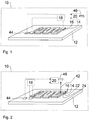
- FIG. 1 shows a schematic, partial perspective view of a first embodiment of a vehicle heater 10, and it also illustrates the monitoring process.
- vehicle heater 10 as well as in all other vehicle heaters described below may be both air heaters and so-called water heaters, for example - and without being limited to - for electric or hybrid cars.
- Air heaters differ from the so-called water heaters in that in air heaters to be heated air flow is passed directly through a heat exchanger of the air heater, while at The so-called water heaters first a liquid, usually a mixture of water - hence the name - and an antifreeze, such as glycol, is passed through a heat exchanger of the water heater to the heat with the help of the liquid and another heat exchanger to the desired location bring.
- a liquid usually a mixture of water - hence the name - and an antifreeze, such as glycol
- Vehicle heater 10 which is shown only schematically as a block, has a main body 12, which in this case is a heat exchanger.
- this heat exchanger 12 is provided to heat air or a liquid, including the heat exchanger 12 may have on its underside unillustrated ribs or similar means for increasing the effective surface for the heat exchange.
- the surface of the heat exchanger 12 has been equipped with a non-intrinsically safe Schuetzmaschinen 14, by means of a thermal spraying process.
- the Schuleiter für 14 is connected to a voltage source, not shown, which may be, for example, an optionally down-pulsed by pulse width modulation to 250 volts DC source.
- the heat conductor layer at its end portions is suitable to contact, which is at the discretion of the skilled person and is also not shown.
- a sensor element 44 Adjacent to the heating conductor layer 14, a sensor element 44 is provided on the surface of the heat exchanger 12, which may be formed for example by a PTC or NTC sensor.
- the sensor element 44 is able to measure the temperature at its mounting location comparatively accurately, and to communicate the measured temperature to a controller 20.
- a sensor layer 16 was sprayed by means of a thermal spraying process, which in the case of the embodiment of FIG. 1 has a positive temperature coefficient, so that at least a PTC characteristic results for the sensor layer 16 at least.
- thermal spraying method may possibly lead to a configuration instead of the schematically shown exact sandwich-type layer structure in which the material of the sensor layer 16 extends at least in sections over the edge regions of the heating conductor layer 14 or in the case of the heating conductor layer 14 even more or less completely buried under the sensor layer 16.
- the electrical conductivity of the sensor layer 16 for normal operating temperatures must be chosen lower than the electrical conductivity of the Schuleitertik 14 to ensure proper operation of the vehicle heater 10.
- the measuring device 18 monitors the temperature-dependent resistance of the sensor layer 16, for example by applying a preferably constant voltage to the end sections of the sensor layer 16 as indicated by the dashed lines and detecting the resulting current flow, for example via a shunt resistor. may be part of the measuring device 18. Occurs now in the heat conductor layer 14, for example, due to a smoldering or arc ignition a local but very strong overheating to, for example, 1000 ° C, this leads to a suitable conditioning of the sensor layer 16 that their total resistance so dominated by their positive temperature coefficient series circuit nature increases that this can be reliably detected by the measuring device 18.
- the sensor element 44, the sensor layer 16, the measuring device 18 and a controller 20 together form a temperature monitoring device which is able to distinguish the three following states and report them as signal 46: normal operation, reversible malfunction and irreversible malfunction. For example, if the sensor element 44 indicates a normal temperature in the range up to 150 ° C., the controller assumes normal operation and reports a corresponding signal 46. If the sensor element 44 reports, for example, an unauthorized temperature rise to 180 ° C., the controller assumes a reversible Malfunction and reports a corresponding signal 46. Such a reversible malfunction could be caused in the case of a water or liquid heating, for example, by missing or standing liquid.
- the controller 20 switches in one In such case, the heat conductor layer 14 temporarily from or at least reduces the heating power. As soon as the sensor element 44 again reports a normal temperature, the heating power can usually be increased again. Preferably, regardless of what the sensor element 44 is currently reporting, the controller 20 assumes an irreversible malfunction if the measuring device 18 has also reported a very high overheating detected by the sensor layer 16 in the area of the heating conductor layer 14 only once. Thus, the signal of the measuring device 18 preferably has priority over the signal of the sensor element 44, because a strong local overheating in any area of the heating conductor layer 14 may not even affect the mounting location of the sensor element 44.
- the controller 20 generates any suitable signal 46 indicative of an irreversible malfunction, preventing re-startup.
- the controller 20 does not have to be exclusively associated with the monitoring device. For example, it is conceivable that the controller 20 controls or regulates the operation of the entire vehicle heating, or that the functions essential for the monitoring device are detected by a controller 20, which is already present in the vehicle anyway.
- FIG. 2 shows a schematic, partial perspective view of a second embodiment of a vehicle heater 10, and it also illustrates the monitoring process.
- the heat conductor layer 14 is sprayed directly onto the body formed by a heat exchanger 12 of the vehicle heater 10.
- the vehicle heating according to FIG. 2 differs from the vehicle heater accordingly FIG. 1 in that the sensor layer 16 in this embodiment comprises three components. Namely, the heat conductor layer 14, which forms a component of the sensor layer 16 in this case, in addition to their actual function as a heating element.
- the measuring device 18 is connected in this case, as indicated by the dashed lines, between the additionally serving as the lower contact layer Schuleiter Anlagen 14 and over the layer 22 provided with a negative temperature coefficient contact layer 24.
- the measuring device 18 can so, in a similar manner as in the context of the embodiment according to FIG. 1 has been explained, reliably detect an irreversible malfunction and provide the controller 20 with a corresponding signal.
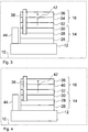
- FIG. 3 shows a schematic, partially sectional view of a third embodiment of a vehicle heater, which simultaneously illustrates the monitoring process.
- the embodiment according to FIG. 3 differs from the embodiment according to FIG. 2 in that the heat exchanger 10 in this case consists of an electrically conductive material, in particular of aluminum. Therefore, in this embodiment, the heating conductor layer 14 is subdivided into a first insulation layer 26, the actual heating layer 28 and a second insulation layer 30. Preferably, all three components of the heating conductor layer are sprayed by a thermal spraying method. Based on the illustration above of the total designated 14 Thompsonleiter für, a generally designated 16 sensor layer is provided, which was also sprayed by a thermal spray process and in turn having three components in this embodiment. Directly above the second insulation layer 30 is a first electrically conductive contact layer 32 onto which a layer 34 of a material having a negative temperature coefficient has been sprayed.
- the layer 34 may be, but is not limited to, in particular, one of the materials proposed in the general part of the description for negative temperature coefficient layers.
- a second upper electrically conductive contact layer 36 was injected.
- a smoldering point leads to such a strong local heating that it can be detected by tapping off the measuring signal between the upper contact layer 36 and the lower contact layer 32 via a measuring device 18, as shown in FIG FIG. 2 is shown.
- an electrically conductive gas channel 38 is located, such as it arises in the case of an arc ignition starting from the actual heating layer 28.
- the gas channel 38 penetrates or penetrates the remaining layers on the side facing away from the base body of the Edelleiter Mrs 14 and leads to a current flow through the layer 34 with a negative temperature coefficient, in the direction of their surface normal 42. This current flow can through a between the lower contact layer 32nd and the upper contact layer 36 switched measuring device are detected.
- FIG. 4 shows a schematic, partially sectional view of a fourth embodiment of a vehicle heater, which also illustrates the monitoring process.
- FIG. 4 illustrated embodiment differs from the embodiment according to FIG. 3 in that the sensor layer 16 instead of the in FIG. 3 a negative temperature coefficient layer 34 comprises an insulating layer 40.
- the sensor layer 16 instead of the in FIG. 3 a negative temperature coefficient layer 34 comprises an insulating layer 40.
- a negative temperature coefficient layer 34 comprises an insulating layer 40.
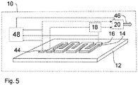
- FIG. 5 shows a schematic, partial perspective view of a fifth embodiment of a vehicle heater, which also illustrates the monitoring process.
- the temperature monitoring device 16, 18, 20, 44, 48 includes a software-programmable or operable controller 20 and independent of the software operating circuit components 48.
- These circuit components 48 are designed to in the case of the occurrence of at least one of the present invention to be distinguished functional disorders to carry out an emergency measure software independent.
- an emergency measure may in particular be the reduction of the heating power, for example the power supply to the heating conductor layer 14 may be completely or partially prevented by the opening of a transistor or other semiconductor switch (not shown) belonging to the circuit components.
- the circuit components 48 may, for example, comprise one or more operational amplifiers serving for comparison purposes, which compare measured values or tapped voltages supplied by the sensors with values or voltages supplied by reference voltage sources so as to be able to detect at least one of the states to be distinguished according to the invention. This is in FIG. 5 indicated by the corresponding input signals of the circuit components 48 shown only schematically.
- the circuit components 48 are further capable of providing the controller 20 with a signal (eg, a particular voltage value) in the event of a malfunction, such that the controller 20 may perform the memory function preferred in the present invention.
- the circuit components 48 may include functions that the controller 20 or the measuring device 18 in the embodiment according to FIG. 1 take over, either redundantly or exclusively make available. In any case, the circuit components 48 result in a certain software independence, which may be desirable in particular for (strongly) safety-relevant functions.
- the respective sensor layers 16 are preferably applied to the base body 12 by a thermal spraying process.
- the respective sensor layer 16 is produced as a separate component and then fixed on the heating conductor layer 14, for example by clamping, gluing or thermal bonding with heat conducting foil. If the sensor or the sensor layer 16 are produced as a separate component, it is of course also in the case of heat-sensitive bodies possible to use for producing the sensor layer 16 conventional baking or high-melting and / or non-injectable materials.
- the above-mentioned insulating layers 26, 30 and 40 may, for example, be aluminum oxide layers, while the heating conductor layer 14 or the actual heating layer 28 may be realized, for example, by a nickel-chromium layer.
- As contact layers 32, 36 may serve as copper layers, for example, and as a layer 34 with a negative temperature coefficient in addition to the already mentioned in the general part of the description materials, for example, a layer of doped with chromium oxide titanium into consideration.
Claims (11)
- Chauffage de véhicule (10) avec un corps de base (12) qui porte une couche thermoconductrice (14) extrinsèque et avec dispositif de contrôle de la température (16, 18, 20, 44) attribué à la couche thermoconductrice (14) caractérisé en ce que le dispositif de contrôle de la température (16, 18, 20, 44) peut différencier au moins les trois états suivants et les annoncer sous forme de signal (46) :- fonctionnement normal,- anomalie de fonctionnement réversible et- anomalie de fonctionnement irréversible,afin que l'état annoncé en dernier puisse être consulté avant une nouvelle mise en service du chauffage du véhicule et qu'en cas d'une anomalie de fonctionnement irréversible une nouvelle mise en service puisse être évitée.
- Chauffage de véhicule selon la revendication 1 caractérisé en ce que le dispositif de contrôle de la température (16, 18, 20, 44) comprend un élément de détection (44) saisissant des températures locales pour détecter des anomalies de fonctionnement réversibles.
- Chauffage de véhicule selon la revendication 1 ou 2 caractérisé en ce que le dispositif de contrôle de la température (16, 18, 20, 44) comprend une couche de détection (16) attribuée au moins par section à la couche thermoconductrice (14) pour détecter des anomalies de fonctionnement irréversibles.
- Chauffage de véhicule (10) selon la revendication 3 caractérisé en ce que la couche de détection (16) a été constituée à l'aide d'un procédé d'injection thermique.
- Chauffage de véhicule (10) selon la revendication 3 ou 4 caractérisé en ce que la couche de détection (16) comporte au moins par zone une caractéristique d'impédance en rapport avec la résistance avec un coefficient de température positif.
- Chauffage de véhicule (10) selon la revendication 3 ou 4 caractérisé en ce que la couche de détection (16) comporte au moins par zone une caractéristique d'impédance en rapport avec la résistance avec un coefficient de température négatif.
- Chauffage de véhicule (10) selon l'une quelconque des revendications précédentes caractérisé en ce que le dispositif de contrôle de la température (16, 18, 20, 44) annonce un fonctionnement normal tant qu'une première valeur de seuil de tempéraure n'est pas dépassée qui est fonction de la température d'un milieu à réchauffer.
- Chauffage de véhicule (10) selon l'une quelconque des revendications précédentes caractérisé en ce que le dispositif de contrôle de la température (16, 18, 20, 44, 48) comprend un contrôleur (20) programmable ou exploitable avec un logiciel et des composants de circuit (48) fonctionnant en fonction d'un logiciel, qui sont conçus de telle manière qu'en cas de survenance d'au moins une des anomalies de fonctionnement citées ils exécutent une mesure d'urgence en fonction du logiciel.
- Procédé pour le contrôle d'un chauffage de véhicule (10) avec les caractéristiques d'une quelconque des revendications précédentes caractérisé en ce que les états suivants sont différenciés et annoncés par le dispositif de contrôle de la température (16, 18, 20, 44) :- fonctionnement normal,- anomalie de fonctionnement réversible et- anomalie de fonctionnement irréversible,afin que l'état annoncé en dernier puisse être consulté avant une nouvelle mise en service du chauffage du véhicule et qu'en cas d'une anomalie de fonctionnement irréversible une nouvelle mise en service puisse être évitée.
- Procédé selon la revendication 9 caractérisé en ce que l'état d'anomalie de fonctionnement réversible est constaté à l'aide d'un élément de détection (44) saisissant les températures locales.
- Procédé selon la revendication 9 ou 10 caractérisé en ce que l'état d'anomalie de fonctionnement irréversible est constaté à l'aide d'une couche de détection (16) attribuée au moins par section à la couche thermoconductrice (14).
Applications Claiming Priority (2)
| Application Number | Priority Date | Filing Date | Title |
|---|---|---|---|
| DE102012202379.8A DE102012202379A1 (de) | 2012-02-16 | 2012-02-16 | Fahrzeugheizung und Verfahren zur Überwachung einer Fahrzeugheizung |
| PCT/EP2013/053100 WO2013121010A1 (fr) | 2012-02-16 | 2013-02-15 | Chauffage de véhicule et procédé de surveillance d'un chauffage de véhicule |
Publications (2)
| Publication Number | Publication Date |
|---|---|
| EP2815627A1 EP2815627A1 (fr) | 2014-12-24 |
| EP2815627B1 true EP2815627B1 (fr) | 2016-04-27 |
Family
ID=47754450
Family Applications (1)
| Application Number | Title | Priority Date | Filing Date |
|---|---|---|---|
| EP13706458.0A Active EP2815627B1 (fr) | 2012-02-16 | 2013-02-15 | Chauffage de véhicule et procédé de contrôle d'un chauffage de véhicule |
Country Status (7)
| Country | Link |
|---|---|
| US (1) | US10625571B2 (fr) |
| EP (1) | EP2815627B1 (fr) |
| JP (1) | JP5938841B2 (fr) |
| KR (1) | KR101605161B1 (fr) |
| CN (1) | CN104115551B (fr) |
| DE (1) | DE102012202379A1 (fr) |
| WO (1) | WO2013121010A1 (fr) |
Families Citing this family (12)
| Publication number | Priority date | Publication date | Assignee | Title |
|---|---|---|---|---|
| JP6383536B2 (ja) * | 2013-12-09 | 2018-08-29 | カルソニックカンセイ株式会社 | 車両空調用安全装置、及びその制御方法 |
| DE102014116275A1 (de) * | 2014-11-07 | 2016-05-12 | Webasto SE | Verfahren zur Herstellung eines Kontaktbereichs für eine Schicht eines elektrischen Heizgeräts sowie Vorrichtung für ein elektrisches Heizgerät für ein Kraftfahrzeug |
| US9829324B2 (en) * | 2014-11-19 | 2017-11-28 | Ford Global Technologies, Llc | Engine block heater failure detection |
| CA3019194A1 (fr) | 2016-03-30 | 2017-10-05 | Marine Canada Acquisition Inc. | Appareil de chauffage de vehicule et commandes associees |
| DE102017206656A1 (de) * | 2017-04-20 | 2018-10-25 | Bayerische Motoren Werke Aktiengesellschaft | Selbstregelnde Scheibenheizungseinrichtung für ein Kraftfahrzeug sowie Kraftfahrzeug |
| CN107352958A (zh) * | 2017-07-12 | 2017-11-17 | 苏州翠南电子科技有限公司 | 一种陶瓷金属摩擦材料 |
| EP3657904A1 (fr) * | 2018-11-26 | 2020-05-27 | KA Group AG | Procédé de fabrication d'un tapis chauffant et tapis chauffant |
| CN109596916B (zh) * | 2018-12-05 | 2021-06-01 | 成都福斯汽车电线有限公司 | 一种电线挤出机螺筒加热故障检测系统及其检测方法 |
| EP3737207A1 (fr) * | 2019-05-10 | 2020-11-11 | Siemens Aktiengesellschaft | Dispositif de chauffage |
| DE102020207875A1 (de) * | 2020-06-24 | 2021-12-30 | Vitesco Technologies GmbH | Elektrische Heizanordnung und elektrische Heizvorrichtung mit einer solchen Heizanordnung |
| FR3116408B1 (fr) * | 2020-11-19 | 2023-10-27 | Valeo Systemes Thermiques | Structure chauffante pour véhicule automobile |
| JP2024516920A (ja) | 2021-02-25 | 2024-04-18 | エリコン メテコ アクチェンゲゼルシャフト、ヴォーレン | 溶射による加熱部材の製造方法及び加熱部材 |
Family Cites Families (19)
| Publication number | Priority date | Publication date | Assignee | Title |
|---|---|---|---|---|
| JPS6039997Y2 (ja) | 1978-09-15 | 1985-11-30 | 松下電工株式会社 | 面状発熱体の温度制御回路 |
| ES2004789A6 (es) | 1987-07-16 | 1989-02-01 | Mendoza Sans Juan Fernando De | Torre de brisa artificial para la descontaminacion de areas de atmosfera polucionada |
| JPH01204383A (ja) * | 1988-02-06 | 1989-08-16 | Ookura Techno Res Kk | 複合熱素子 |
| JPH02121410U (fr) | 1989-03-20 | 1990-10-02 | ||
| CA2416831C (fr) * | 2000-06-14 | 2007-07-24 | Elias Russegger | Dispositif de chauffage electrique |
| JP2003109728A (ja) | 2001-09-28 | 2003-04-11 | Matsushita Electric Ind Co Ltd | 印刷ヒータ |
| DE10213407A1 (de) | 2002-03-26 | 2003-10-09 | Behr Gmbh & Co | Heizkörper und Verfahren zur Steuerung eines Heizkörpers, insbesondere für ein Kraftfahrzeug |
| DE10220413A1 (de) | 2002-05-08 | 2003-11-27 | Behr Gmbh & Co | Verfahren und Vorrichtung zur Temperaturüberwachung eines elektrischen Heizelements |
| DE60312398T2 (de) | 2003-08-14 | 2007-11-08 | Imetec S.P.A., Azzano S.P. | Heizdecke |
| DE102005052274B4 (de) * | 2005-10-27 | 2010-04-08 | E.G.O. Elektro-Gerätebau GmbH | Kochgerät |
| CN100594746C (zh) | 2006-06-28 | 2010-03-17 | 王清传 | 防止发热装置过热的方法及电路 |
| NL2000685C2 (nl) | 2007-06-06 | 2008-12-09 | Ferro Techniek Holding Bv | Verwarmingselement en vloeistofhouder voorzien van een dergelijk verwarmingselement. |
| DE102008006017B4 (de) * | 2008-01-25 | 2010-08-12 | Beurer Gmbh | Schmiegsames Wärmegerät |
| TW201015654A (en) | 2008-07-11 | 2010-04-16 | Applied Materials Inc | Chamber components for CVD applications |
| NL2001806C2 (en) * | 2008-07-15 | 2010-01-18 | Otter Controls Ltd | Heating element and method for operating such a heating element. |
| EP2491758A1 (fr) * | 2009-10-22 | 2012-08-29 | Datec Coating Corporation | Procédé de liaison par fusion d'un élément chauffant à base de thermoplastique résistant aux températures élevées à un substrat |
| DE102009052535C5 (de) * | 2009-11-11 | 2023-06-01 | Nbhx Trim Gmbh | Innenraumverkleidung |
| DE102011000719A1 (de) * | 2010-02-13 | 2011-08-18 | DBK David + Baader GmbH, 76870 | Verfahren zum Ansteuern eines elektrischen Heizers und elektrischer Heizer |
| DE102011105675A1 (de) | 2010-07-15 | 2012-01-19 | W.E.T. Automotive Systems Ag | Elektrische Leitung |
-
2012
- 2012-02-16 DE DE102012202379.8A patent/DE102012202379A1/de not_active Withdrawn
-
2013
- 2013-02-15 EP EP13706458.0A patent/EP2815627B1/fr active Active
- 2013-02-15 WO PCT/EP2013/053100 patent/WO2013121010A1/fr active Application Filing
- 2013-02-15 JP JP2014556109A patent/JP5938841B2/ja active Active
- 2013-02-15 US US14/379,066 patent/US10625571B2/en active Active
- 2013-02-15 CN CN201380009585.7A patent/CN104115551B/zh active Active
- 2013-02-15 KR KR1020147022250A patent/KR101605161B1/ko active IP Right Grant
Non-Patent Citations (1)
| Title |
|---|
| None * |
Also Published As
| Publication number | Publication date |
|---|---|
| DE102012202379A1 (de) | 2015-08-13 |
| KR101605161B1 (ko) | 2016-03-22 |
| CN104115551B (zh) | 2017-03-29 |
| CN104115551A (zh) | 2014-10-22 |
| JP2015511377A (ja) | 2015-04-16 |
| WO2013121010A1 (fr) | 2013-08-22 |
| US10625571B2 (en) | 2020-04-21 |
| KR20140109495A (ko) | 2014-09-15 |
| JP5938841B2 (ja) | 2016-06-22 |
| US20150014293A1 (en) | 2015-01-15 |
| EP2815627A1 (fr) | 2014-12-24 |
Similar Documents
| Publication | Publication Date | Title |
|---|---|---|
| EP2815627B1 (fr) | Chauffage de véhicule et procédé de contrôle d'un chauffage de véhicule | |
| EP2815626B1 (fr) | Procédé de fabrication d'un chauffage de véhicule et chauffage de véhicule | |
| EP2815628B1 (fr) | Chauffage de véhicule et procédé de fabrication d'un chauffage de véhicule | |
| EP1989922A1 (fr) | Procédé et dispositif de reconaissance d'une sonde de température raccordé à une commande | |
| WO2013072128A1 (fr) | Capteur d'humidité intégré et procédé de fabrication dudit capteur d'humidité | |
| WO2009027042A1 (fr) | Dispositif de chauffage, procédé pour faire fonctionner un dispositif de chauffage et appareil de chauffage électrique appartenant à un tel dispositif de chauffage | |
| WO2011086184A1 (fr) | Dispositif de commande électronique | |
| DE10146947C5 (de) | Elektrisches Bauelement | |
| EP3724021B1 (fr) | Module électrochimique de stockage d'énergie et véhicule | |
| DE19707664C2 (de) | Vorrichtung und Verfahren zur Steuerung oder Regelung der Temperatur von beheizten Flächen | |
| DE3221919A1 (de) | Elektrische sicherung mit einem schmelzelement | |
| EP1610048B1 (fr) | Elément de chauffage pour liquides | |
| EP0643401B1 (fr) | Fusible électrique dépendant de la charge | |
| DE102017109507B4 (de) | Elektrische Drahtheizeinrichtung für einen Fahrzeuginnenraum | |
| WO2010046062A2 (fr) | Agencement avec résistance de freinage | |
| DE102022125282A1 (de) | Versorgungsstation für elektrisch betreibbare Fahrzeuge | |
| EP0640816A1 (fr) | Capteur de température à thermistor hybride | |
| DE102007056917A1 (de) | Verfahren zum Fertigungstoleranzausgleich von elektrischen Verbrauchern | |
| EP3930421A1 (fr) | Dispositif de chauffage doté d'un dispositif de mesure de la température et procédé de mesure de la température sur le dispositif de chauffage et de fabrication | |
| DE102017207372A1 (de) | Sicherheitsabschaltung der Sitzheizung im KFZ | |
| DE102010031441A1 (de) | Elektrisch programmierbare Brücke | |
| DE102014001788A1 (de) | PTC-Heizsystem für Flüssigkeitsfilter |
Legal Events
| Date | Code | Title | Description |
|---|---|---|---|
| PUAI | Public reference made under article 153(3) epc to a published international application that has entered the european phase |
Free format text: ORIGINAL CODE: 0009012 |
|
| 17P | Request for examination filed |
Effective date: 20140704 |
|
| AK | Designated contracting states |
Kind code of ref document: A1 Designated state(s): AL AT BE BG CH CY CZ DE DK EE ES FI FR GB GR HR HU IE IS IT LI LT LU LV MC MK MT NL NO PL PT RO RS SE SI SK SM TR |
|
| AX | Request for extension of the european patent |
Extension state: BA ME |
|
| DAX | Request for extension of the european patent (deleted) | ||
| GRAP | Despatch of communication of intention to grant a patent |
Free format text: ORIGINAL CODE: EPIDOSNIGR1 |
|
| INTG | Intention to grant announced |
Effective date: 20150921 |
|
| GRAS | Grant fee paid |
Free format text: ORIGINAL CODE: EPIDOSNIGR3 |
|
| INTG | Intention to grant announced |
Effective date: 20160219 |
|
| GRAA | (expected) grant |
Free format text: ORIGINAL CODE: 0009210 |
|
| AK | Designated contracting states |
Kind code of ref document: B1 Designated state(s): AL AT BE BG CH CY CZ DE DK EE ES FI FR GB GR HR HU IE IS IT LI LT LU LV MC MK MT NL NO PL PT RO RS SE SI SK SM TR |
|
| REG | Reference to a national code |
Ref country code: GB Ref legal event code: FG4D Free format text: NOT ENGLISH |
|
| REG | Reference to a national code |
Ref country code: CH Ref legal event code: EP |
|
| REG | Reference to a national code |
Ref country code: AT Ref legal event code: REF Ref document number: 795994 Country of ref document: AT Kind code of ref document: T Effective date: 20160515 |
|
| REG | Reference to a national code |
Ref country code: IE Ref legal event code: FG4D Free format text: LANGUAGE OF EP DOCUMENT: GERMAN |
|
| REG | Reference to a national code |
Ref country code: DE Ref legal event code: R096 Ref document number: 502013002787 Country of ref document: DE |
|
| REG | Reference to a national code |
Ref country code: LT Ref legal event code: MG4D |
|
| REG | Reference to a national code |
Ref country code: NL Ref legal event code: MP Effective date: 20160427 |
|
| PG25 | Lapsed in a contracting state [announced via postgrant information from national office to epo] |
Ref country code: NL Free format text: LAPSE BECAUSE OF FAILURE TO SUBMIT A TRANSLATION OF THE DESCRIPTION OR TO PAY THE FEE WITHIN THE PRESCRIBED TIME-LIMIT Effective date: 20160427 |
|
| PG25 | Lapsed in a contracting state [announced via postgrant information from national office to epo] |
Ref country code: LT Free format text: LAPSE BECAUSE OF FAILURE TO SUBMIT A TRANSLATION OF THE DESCRIPTION OR TO PAY THE FEE WITHIN THE PRESCRIBED TIME-LIMIT Effective date: 20160427 Ref country code: FI Free format text: LAPSE BECAUSE OF FAILURE TO SUBMIT A TRANSLATION OF THE DESCRIPTION OR TO PAY THE FEE WITHIN THE PRESCRIBED TIME-LIMIT Effective date: 20160427 Ref country code: NO Free format text: LAPSE BECAUSE OF FAILURE TO SUBMIT A TRANSLATION OF THE DESCRIPTION OR TO PAY THE FEE WITHIN THE PRESCRIBED TIME-LIMIT Effective date: 20160727 Ref country code: PL Free format text: LAPSE BECAUSE OF FAILURE TO SUBMIT A TRANSLATION OF THE DESCRIPTION OR TO PAY THE FEE WITHIN THE PRESCRIBED TIME-LIMIT Effective date: 20160427 |
|
| PG25 | Lapsed in a contracting state [announced via postgrant information from national office to epo] |
Ref country code: PT Free format text: LAPSE BECAUSE OF FAILURE TO SUBMIT A TRANSLATION OF THE DESCRIPTION OR TO PAY THE FEE WITHIN THE PRESCRIBED TIME-LIMIT Effective date: 20160829 Ref country code: LV Free format text: LAPSE BECAUSE OF FAILURE TO SUBMIT A TRANSLATION OF THE DESCRIPTION OR TO PAY THE FEE WITHIN THE PRESCRIBED TIME-LIMIT Effective date: 20160427 Ref country code: SE Free format text: LAPSE BECAUSE OF FAILURE TO SUBMIT A TRANSLATION OF THE DESCRIPTION OR TO PAY THE FEE WITHIN THE PRESCRIBED TIME-LIMIT Effective date: 20160427 Ref country code: RS Free format text: LAPSE BECAUSE OF FAILURE TO SUBMIT A TRANSLATION OF THE DESCRIPTION OR TO PAY THE FEE WITHIN THE PRESCRIBED TIME-LIMIT Effective date: 20160427 Ref country code: GR Free format text: LAPSE BECAUSE OF FAILURE TO SUBMIT A TRANSLATION OF THE DESCRIPTION OR TO PAY THE FEE WITHIN THE PRESCRIBED TIME-LIMIT Effective date: 20160728 Ref country code: HR Free format text: LAPSE BECAUSE OF FAILURE TO SUBMIT A TRANSLATION OF THE DESCRIPTION OR TO PAY THE FEE WITHIN THE PRESCRIBED TIME-LIMIT Effective date: 20160427 Ref country code: ES Free format text: LAPSE BECAUSE OF FAILURE TO SUBMIT A TRANSLATION OF THE DESCRIPTION OR TO PAY THE FEE WITHIN THE PRESCRIBED TIME-LIMIT Effective date: 20160427 |
|
| PG25 | Lapsed in a contracting state [announced via postgrant information from national office to epo] |
Ref country code: IT Free format text: LAPSE BECAUSE OF FAILURE TO SUBMIT A TRANSLATION OF THE DESCRIPTION OR TO PAY THE FEE WITHIN THE PRESCRIBED TIME-LIMIT Effective date: 20160427 |
|
| REG | Reference to a national code |
Ref country code: DE Ref legal event code: R097 Ref document number: 502013002787 Country of ref document: DE |
|
| PG25 | Lapsed in a contracting state [announced via postgrant information from national office to epo] |
Ref country code: SK Free format text: LAPSE BECAUSE OF FAILURE TO SUBMIT A TRANSLATION OF THE DESCRIPTION OR TO PAY THE FEE WITHIN THE PRESCRIBED TIME-LIMIT Effective date: 20160427 Ref country code: EE Free format text: LAPSE BECAUSE OF FAILURE TO SUBMIT A TRANSLATION OF THE DESCRIPTION OR TO PAY THE FEE WITHIN THE PRESCRIBED TIME-LIMIT Effective date: 20160427 Ref country code: RO Free format text: LAPSE BECAUSE OF FAILURE TO SUBMIT A TRANSLATION OF THE DESCRIPTION OR TO PAY THE FEE WITHIN THE PRESCRIBED TIME-LIMIT Effective date: 20160427 Ref country code: DK Free format text: LAPSE BECAUSE OF FAILURE TO SUBMIT A TRANSLATION OF THE DESCRIPTION OR TO PAY THE FEE WITHIN THE PRESCRIBED TIME-LIMIT Effective date: 20160427 Ref country code: CZ Free format text: LAPSE BECAUSE OF FAILURE TO SUBMIT A TRANSLATION OF THE DESCRIPTION OR TO PAY THE FEE WITHIN THE PRESCRIBED TIME-LIMIT Effective date: 20160427 |
|
| PG25 | Lapsed in a contracting state [announced via postgrant information from national office to epo] |
Ref country code: SM Free format text: LAPSE BECAUSE OF FAILURE TO SUBMIT A TRANSLATION OF THE DESCRIPTION OR TO PAY THE FEE WITHIN THE PRESCRIBED TIME-LIMIT Effective date: 20160427 |
|
| PLBE | No opposition filed within time limit |
Free format text: ORIGINAL CODE: 0009261 |
|
| STAA | Information on the status of an ep patent application or granted ep patent |
Free format text: STATUS: NO OPPOSITION FILED WITHIN TIME LIMIT |
|
| 26N | No opposition filed |
Effective date: 20170130 |
|
| REG | Reference to a national code |
Ref country code: FR Ref legal event code: PLFP Year of fee payment: 5 |
|
| PG25 | Lapsed in a contracting state [announced via postgrant information from national office to epo] |
Ref country code: BE Free format text: LAPSE BECAUSE OF NON-PAYMENT OF DUE FEES Effective date: 20170228 Ref country code: SI Free format text: LAPSE BECAUSE OF FAILURE TO SUBMIT A TRANSLATION OF THE DESCRIPTION OR TO PAY THE FEE WITHIN THE PRESCRIBED TIME-LIMIT Effective date: 20160427 |
|
| PG25 | Lapsed in a contracting state [announced via postgrant information from national office to epo] |
Ref country code: MC Free format text: LAPSE BECAUSE OF FAILURE TO SUBMIT A TRANSLATION OF THE DESCRIPTION OR TO PAY THE FEE WITHIN THE PRESCRIBED TIME-LIMIT Effective date: 20160427 |
|
| REG | Reference to a national code |
Ref country code: CH Ref legal event code: PL |
|
| PG25 | Lapsed in a contracting state [announced via postgrant information from national office to epo] |
Ref country code: LI Free format text: LAPSE BECAUSE OF NON-PAYMENT OF DUE FEES Effective date: 20170228 Ref country code: CH Free format text: LAPSE BECAUSE OF NON-PAYMENT OF DUE FEES Effective date: 20170228 |
|
| REG | Reference to a national code |
Ref country code: IE Ref legal event code: MM4A |
|
| PG25 | Lapsed in a contracting state [announced via postgrant information from national office to epo] |
Ref country code: LU Free format text: LAPSE BECAUSE OF NON-PAYMENT OF DUE FEES Effective date: 20170215 |
|
| REG | Reference to a national code |
Ref country code: BE Ref legal event code: MM Effective date: 20170228 |
|
| REG | Reference to a national code |
Ref country code: FR Ref legal event code: PLFP Year of fee payment: 6 |
|
| PG25 | Lapsed in a contracting state [announced via postgrant information from national office to epo] |
Ref country code: IE Free format text: LAPSE BECAUSE OF NON-PAYMENT OF DUE FEES Effective date: 20170215 |
|
| PG25 | Lapsed in a contracting state [announced via postgrant information from national office to epo] |
Ref country code: MT Free format text: LAPSE BECAUSE OF FAILURE TO SUBMIT A TRANSLATION OF THE DESCRIPTION OR TO PAY THE FEE WITHIN THE PRESCRIBED TIME-LIMIT Effective date: 20160427 |
|
| PG25 | Lapsed in a contracting state [announced via postgrant information from national office to epo] |
Ref country code: AL Free format text: LAPSE BECAUSE OF FAILURE TO SUBMIT A TRANSLATION OF THE DESCRIPTION OR TO PAY THE FEE WITHIN THE PRESCRIBED TIME-LIMIT Effective date: 20160427 |
|
| REG | Reference to a national code |
Ref country code: AT Ref legal event code: MM01 Ref document number: 795994 Country of ref document: AT Kind code of ref document: T Effective date: 20180215 |
|
| PG25 | Lapsed in a contracting state [announced via postgrant information from national office to epo] |
Ref country code: AT Free format text: LAPSE BECAUSE OF NON-PAYMENT OF DUE FEES Effective date: 20180215 |
|
| PG25 | Lapsed in a contracting state [announced via postgrant information from national office to epo] |
Ref country code: HU Free format text: LAPSE BECAUSE OF FAILURE TO SUBMIT A TRANSLATION OF THE DESCRIPTION OR TO PAY THE FEE WITHIN THE PRESCRIBED TIME-LIMIT; INVALID AB INITIO Effective date: 20130215 |
|
| PG25 | Lapsed in a contracting state [announced via postgrant information from national office to epo] |
Ref country code: BG Free format text: LAPSE BECAUSE OF FAILURE TO SUBMIT A TRANSLATION OF THE DESCRIPTION OR TO PAY THE FEE WITHIN THE PRESCRIBED TIME-LIMIT Effective date: 20160427 |
|
| PG25 | Lapsed in a contracting state [announced via postgrant information from national office to epo] |
Ref country code: CY Free format text: LAPSE BECAUSE OF FAILURE TO SUBMIT A TRANSLATION OF THE DESCRIPTION OR TO PAY THE FEE WITHIN THE PRESCRIBED TIME-LIMIT Effective date: 20160427 |
|
| PG25 | Lapsed in a contracting state [announced via postgrant information from national office to epo] |
Ref country code: MK Free format text: LAPSE BECAUSE OF FAILURE TO SUBMIT A TRANSLATION OF THE DESCRIPTION OR TO PAY THE FEE WITHIN THE PRESCRIBED TIME-LIMIT Effective date: 20160427 |
|
| PG25 | Lapsed in a contracting state [announced via postgrant information from national office to epo] |
Ref country code: TR Free format text: LAPSE BECAUSE OF FAILURE TO SUBMIT A TRANSLATION OF THE DESCRIPTION OR TO PAY THE FEE WITHIN THE PRESCRIBED TIME-LIMIT Effective date: 20160427 |
|
| PG25 | Lapsed in a contracting state [announced via postgrant information from national office to epo] |
Ref country code: IS Free format text: LAPSE BECAUSE OF FAILURE TO SUBMIT A TRANSLATION OF THE DESCRIPTION OR TO PAY THE FEE WITHIN THE PRESCRIBED TIME-LIMIT Effective date: 20160827 |
|
| PGFP | Annual fee paid to national office [announced via postgrant information from national office to epo] |
Ref country code: FR Payment date: 20230220 Year of fee payment: 11 |
|
| PGFP | Annual fee paid to national office [announced via postgrant information from national office to epo] |
Ref country code: GB Payment date: 20230221 Year of fee payment: 11 Ref country code: DE Payment date: 20230216 Year of fee payment: 11 |