EP2815627B1 - Vehicle heating and method for controlling a vehicle heating - Google Patents
Vehicle heating and method for controlling a vehicle heating Download PDFInfo
- Publication number
- EP2815627B1 EP2815627B1 EP13706458.0A EP13706458A EP2815627B1 EP 2815627 B1 EP2815627 B1 EP 2815627B1 EP 13706458 A EP13706458 A EP 13706458A EP 2815627 B1 EP2815627 B1 EP 2815627B1
- Authority
- EP
- European Patent Office
- Prior art keywords
- layer
- vehicle heater
- sensor
- monitoring device
- temperature
- Prior art date
- Legal status (The legal status is an assumption and is not a legal conclusion. Google has not performed a legal analysis and makes no representation as to the accuracy of the status listed.)
- Active
Links
Images
Classifications
-
- B—PERFORMING OPERATIONS; TRANSPORTING
- B60—VEHICLES IN GENERAL
- B60H—ARRANGEMENTS OF HEATING, COOLING, VENTILATING OR OTHER AIR-TREATING DEVICES SPECIALLY ADAPTED FOR PASSENGER OR GOODS SPACES OF VEHICLES
- B60H1/00—Heating, cooling or ventilating [HVAC] devices
- B60H1/22—Heating, cooling or ventilating [HVAC] devices the heat being derived otherwise than from the propulsion plant
- B60H1/2215—Heating, cooling or ventilating [HVAC] devices the heat being derived otherwise than from the propulsion plant the heat being derived from electric heaters
- B60H1/2218—Heating, cooling or ventilating [HVAC] devices the heat being derived otherwise than from the propulsion plant the heat being derived from electric heaters controlling the operation of electric heaters
-
- H—ELECTRICITY
- H05—ELECTRIC TECHNIQUES NOT OTHERWISE PROVIDED FOR
- H05B—ELECTRIC HEATING; ELECTRIC LIGHT SOURCES NOT OTHERWISE PROVIDED FOR; CIRCUIT ARRANGEMENTS FOR ELECTRIC LIGHT SOURCES, IN GENERAL
- H05B1/00—Details of electric heating devices
- H05B1/02—Automatic switching arrangements specially adapted to apparatus ; Control of heating devices
- H05B1/0227—Applications
- H05B1/023—Industrial applications
- H05B1/0236—Industrial applications for vehicles
-
- H—ELECTRICITY
- H05—ELECTRIC TECHNIQUES NOT OTHERWISE PROVIDED FOR
- H05B—ELECTRIC HEATING; ELECTRIC LIGHT SOURCES NOT OTHERWISE PROVIDED FOR; CIRCUIT ARRANGEMENTS FOR ELECTRIC LIGHT SOURCES, IN GENERAL
- H05B3/00—Ohmic-resistance heating
- H05B3/20—Heating elements having extended surface area substantially in a two-dimensional plane, e.g. plate-heater
- H05B3/22—Heating elements having extended surface area substantially in a two-dimensional plane, e.g. plate-heater non-flexible
- H05B3/26—Heating elements having extended surface area substantially in a two-dimensional plane, e.g. plate-heater non-flexible heating conductor mounted on insulating base
- H05B3/262—Heating elements having extended surface area substantially in a two-dimensional plane, e.g. plate-heater non-flexible heating conductor mounted on insulating base the insulating base being an insulated metal plate
-
- H—ELECTRICITY
- H05—ELECTRIC TECHNIQUES NOT OTHERWISE PROVIDED FOR
- H05B—ELECTRIC HEATING; ELECTRIC LIGHT SOURCES NOT OTHERWISE PROVIDED FOR; CIRCUIT ARRANGEMENTS FOR ELECTRIC LIGHT SOURCES, IN GENERAL
- H05B2203/00—Aspects relating to Ohmic resistive heating covered by group H05B3/00
- H05B2203/002—Heaters using a particular layout for the resistive material or resistive elements
- H05B2203/003—Heaters using a particular layout for the resistive material or resistive elements using serpentine layout
-
- H—ELECTRICITY
- H05—ELECTRIC TECHNIQUES NOT OTHERWISE PROVIDED FOR
- H05B—ELECTRIC HEATING; ELECTRIC LIGHT SOURCES NOT OTHERWISE PROVIDED FOR; CIRCUIT ARRANGEMENTS FOR ELECTRIC LIGHT SOURCES, IN GENERAL
- H05B2203/00—Aspects relating to Ohmic resistive heating covered by group H05B3/00
- H05B2203/013—Heaters using resistive films or coatings
-
- H—ELECTRICITY
- H05—ELECTRIC TECHNIQUES NOT OTHERWISE PROVIDED FOR
- H05B—ELECTRIC HEATING; ELECTRIC LIGHT SOURCES NOT OTHERWISE PROVIDED FOR; CIRCUIT ARRANGEMENTS FOR ELECTRIC LIGHT SOURCES, IN GENERAL
- H05B2203/00—Aspects relating to Ohmic resistive heating covered by group H05B3/00
- H05B2203/022—Heaters specially adapted for heating gaseous material
- H05B2203/023—Heaters of the type used for electrically heating the air blown in a vehicle compartment by the vehicle heating system
Definitions
- the invention relates to a vehicle heater having a base body, which carries a non-intrinsically safe Schuetzmaschinen, wherein the Schuleiter lamb is associated with a temperature monitoring device.
- the invention relates to a method for monitoring a vehicle heating.
- the main body can be, for example, a heat exchanger, in particular a metal / air and / or a metal / liquid heat exchanger.
- the non-intrinsically safe heating conductor layer may be, for example, but not limited to be subjected to relatively high voltages (for example, 250 volts DC), too high voltages can be clocked down, for example by a pulse width modulation, if this appears advantageous.
- relatively high voltages for example, 250 volts DC
- relatively high voltages are often available, for example, in electric or hybrid vehicles anyway.
- electric vehicle heaters with a power in the range of three to eight kilowatts can certainly operate, but the scope of the invention is by no means limited to this power range or these vehicle types.
- a vehicle heater with a heat conductor layer in the form of a non-intrinsically safe heating element is for example from Patent EP 1 361 089 B1 known.
- three alternative sensors for surface-specific detection of a heat radiation representing the heating element are provided for temperature monitoring, wherein the heating element is designed as a meandering corrugated fin.
- One of these sensors is designed as a non-contact infrared sensor.
- the heating element contacting sensor is provided in the form of an integrated in the heating element electrical resistance line.
- the third sensor proposed there is likewise arranged in the region of the heating element or integrated into it and operates on the basis of a temperature-sensitive optical waveguide.
- the three sensors deliver a corresponding measurement signal to a control unit, which generates a control signal in the event of a fault for safe disconnection or for power reduction of the heating element. Should a permanent failure occur with this vehicle heater, then it is to be assumed that this permanent defect will lead to overheating even at the next operating cycle and thus (at best) to a new shutdown or a new power reduction.
- a vehicle heater according to the preamble of claim 1 is made EP 1 349 428 A2 known.
- the invention has the object of developing the generic vehicle heaters and the generic method for monitoring a vehicle heating so that the security is increased.
- a vehicle heater with a base body which carries a non-intrinsically safe Schuetzmaschinen, wherein the Schuleiter lamb is associated with a temperature monitoring device.
- the temperature monitoring device is designed to distinguish at least the three following states and report them as a signal: normal operation, reversible malfunction and irreversible malfunction. From a normal operation of the vehicle heating can be assumed, for example, at a temperature up to 150 ° C.
- a reversible malfunction which may be caused, for example, by missing or standing liquid in the case of a water or liquid heater
- the temperature rises above the exemplified value of 150 ° C, so that, for example, when reaching a temperature of 180 ° C a temporary Shutdown of the heat conductor layer or at least a reduction in power can take place.
- An irreversible malfunction may be present, for example, when in very rare cases a smoldering point or an arc ignition has occurred. Although such rare events usually lead only to local, but extremely strong overheating, in which, for example, temperatures in the range of 1000 ° C can be achieved.
- the temperature monitoring device may include a sensor element detecting local temperatures for detecting reversible malfunctions.
- This sensor element may be, for example, a conventional PTC or NTC sensor element.
- Such sensor elements are able to detect the local temperatures very accurately, sometimes up to a few ° C exactly. They are therefore particularly suitable, for example, to detect the temperature increase from 150 ° C. to 180 ° C. mentioned above by way of example.
- the temperature monitoring device for detecting irreversible malfunctions comprises a sensor layer at least partially associated with the heat conductor layer.
- This sensor layer is then preferably at least able to reliably and quickly detect local and very strong overheating of the heat conductor layer, as they occur, for example, in the case of the mentioned smoldering points or arcs.
- the sensor layer is preferably arranged above or below the heat conductor layer.
- the sensor layer can cover the heat conductor layer more or less completely (connection areas and the like can optionally be omitted). Since a sensor layer is always an at least partially flat layer in the broadest sense, for example, a sensor layer consisting of one or more (possibly very narrow) strips can also be considered.
- the sensor layer can follow a heating conductor layer arranged in a meandering pattern, for example, but it preferably completely covers the heating conductor layer (connection areas may, as mentioned, if appropriate be omitted), or the sensor layer can cover larger areas of the body.
- the sensor layer can be laid over a meander-shaped heating conductor layer as a sensor layer which is rectangular in plan view. In this case, both solutions come into consideration, in which the sensor layer is arranged directly above the heating conductor layer, so that the sensor layer thus at least partially contacts the heating conductor layer, as well as solutions in which at least one intermediate layer is provided.
- the sensor layer is conditioned in such a way that it already strongly changes its resistance or its impedance in the case of local overheating.
- the sensor layer has been formed by means of a thermal spraying process.
- thermal spraying methods are suitable as spraying methods.
- thermal spraying sensor layers can be produced without the body is exposed to the usual temperatures for baking processes.
- Such spraying of sensor layers can be performed comparably favorably as baking process, but it limits the requirements for the temperature compatibility of the base body used (or to the already carried by the body materials) significantly less. Therefore come through the use of a spray-on for the body also materials in question, which would melt at usual for baking processes temperatures or any other negative change in their material properties with regard to the intended use.
- the main body can consist entirely or partially of aluminum by using a suitable spray-on process.
- thermal spray processes are plasma spraying, cold spraying or flame spraying.
- Cold spray plasma spraying and suspension flame spraying are currently considered to be particularly suitable thermal spray processes.
- a gas such as nitrogen
- a suspension with the particles to be sprayed on is first prepared in order to then inject this suspension into a flame.
- the liquid evaporates at least partially, but preferably completely, and (ideally) only the respective particles strike the target surface, which makes it possible to produce dense layers.
- the method in question for spraying the sensor layer has in common that the base body does not have to be exposed to the usual high temperatures for baking processes.
- the base body is only exposed to temperatures of less than 800 ° C, less than 650 ° C and even less than 500 ° C. It will be appreciated that the lower the temperatures that can be maintained, the greater the usefulness of the body (and / or any components already carried by it) increases. It should be clear that the phrase "exposure to temperatures" should not necessarily mean that the entire body should or must accept this temperature. Rather, it is only important that the body is not partially exposed to temperatures that could damage it.
- the base body already carries components (for example, electrical or other components) in the areas not directly exposed to the spraying process, which only very much lower temperatures than 500 ° C can withstand, for example, only 100 ° C or even less.
- the sensor layer is produced by means of a powder, wherein powder particles of the powder are present in agglomerated form or are brought into agglomerated form and wherein the non-agglomerated powder particles have an average particle size d50 of less than 20 .mu.m, preferably less than 10 have ⁇ m.
- barium titanate powder which in some cases can be used to create the sensor layer, typically has a crystal size of less than 10 microns (for example, between 2 microns and 8 microns or between 4 microns and 5 microns).
- This particle size may be too small for some thermal spraying processes (such as plasma spraying processes), as they cause clogging of orifices of the spray gun used in these processes (or any other component of the device used for spraying).
- agglomerates in each case a plurality of powder particles may be connected to the shell material, which may for example have a plastic such as polyvinyl alcohol as an ingredient. Because the agglomerates are at least predominantly larger than individual powder particles, clogging of the spray gun (or any other component of the device used for spraying) can thus be avoided, at least in many cases.
- the production and use of agglomerates is not limited to barium titanate powders. Rather, this technique can be used for any in the invention in question in question powder with too small powder particles.
- the shell material used to form the agglomerates should preferably have a specific electrical conductivity which is at least as great as the specific electrical conductivity of the powder particles (at a normal operating temperature of the vehicle heating), unless the agglomerates during spraying be destroyed or the shell material at least partially remains part of the sprayed sensor layer.
- destroying the agglomerates or at least partially removing the cladding material can also be specifically supported so that the properties of the sensor layer are (at least largely) determined by the property of the powder particles.
- suitable thermal, chemical and / or physical processes or post-treatment steps can be carried out as soon as the agglomerates have passed the sections which are prone to clogging.
- suitable thermal, chemical and / or physical processes or post-treatment steps can be carried out as soon as the agglomerates have passed the sections which are prone to clogging.
- agglomerated form For this purpose, suitable thermal, chemical and / or physical processes or post-treatment steps can be carried out as soon as the agglomerates have passed the sections which are prone to clogging.
- a first step the corresponding material can be provided in its original state.
- a conversion then takes place into a solid material, in particular by means of sintering.
- the solid material is pulverized by crushing the solid material.
- the powder particles can be agglomerated by the use of a binder system as well as subsequent drying and burn-out of the binder.
- a granulated perovskite powder having a predetermined average particle size d50 is used, the procedure may be as follows: In a first process stage, weighing is carried out and mixing, dissolving the salts in acid, precipitation with caustic, filtering and washing and drying. In a second process stage, a heat treatment for phase reaction and / or conversion can then be carried out. In a third process stage, wet milling can then be carried out to the desired fineness, wherein in a fourth process stage fractionation by sifting or sieving, a check of the finished powder material and / or a treatment of residual amounts can take place. In particular, in cases in which the main body and possibly already carried by these components have sufficient heat resistance, of course, the conventional stoving can be applied, of course, to form the sensor layer (or other layers).
- the sensor layer at least partially has a resistance or impedance characteristic with a positive temperature coefficient.
- This approach is particularly useful when the sensor layer has an elongate extension with two end portions between which a measurement signal is tapped to monitor the sensor layer for currents occurring in its longitudinal direction (or forced).
- the operation may then be similar to the use of a PTC resistor ladder because, due to the series circuit nature of such an elongated extent, sufficient heating of a comparatively short length is sufficient to increase the total resistance (or total impedance) to a point where the temperature exceeds a local threshold can be reliably detected.
- Temperaturschwellenwertschreibauerschreitonneitonneitonneitonne can be determined so certainly certainly certainly.
- An example of obtaining a resistance characteristic with a positive temperature coefficient is the use of the above-mentioned barium titanate powder, wherein the relatively inexpensive barium titanate is or will be doped with lead.
- the sensor layer has at least partially a resistance or impedance characteristic with a negative temperature coefficient.
- a negative temperature coefficient comes into consideration, in particular, if the sensor layer in the broadest sense is an at least partially flat layer which is to be monitored with regard to current flows in the direction of its (possibly respective) surface normal.
- a flat sensor layer is to be understood as meaning, for example, a sensor layer consisting of one or more strips (possibly very narrow), for example also one Strip existing layer in which the strip wraps around a cylinder surface several times and at different heights, resulting in a plurality of (differential) surface normals.
- the top and the bottom of the negative temperature coefficient layer will each be equipped with a likewise flat electrode for tapping a measuring signal.
- a sensor layer can be regarded as a parallel connection of a multiplicity of resistances or impedances (capacitances), so that even a local temperature threshold value overshoot leads to a reliably detectable decrease in the total resistance (or of the total impedance). Temperature threshold overruns that affect larger areas or even the entire area can of course also be determined with certainty. Likewise, for example, a local breakdown or a local arcing between the electrodes can be determined or, ideally, foreseen and thus avoided.
- the term negative temperature coefficient is to be understood here in the broadest sense.
- materials such as silicon dioxide, silicon carbide, alumina, titanium oxide and other ceramics may be used.
- a glass ceramic can be provided that this contains one or more alkali metals, for example in an amount up to ten percent by weight.
- the glass ceramic is or is doped with zirconium oxide, zirconium silicate, quartz, titanium oxide and / or zinc oxide. The proportion of doping can be, for example, up to three percent by weight.
- the temperature monitoring device as long as a normal operation reports, such as a first temperature threshold is not exceeded, which depends on the temperature of a medium to be heated.
- a medium temperature of for example - 40 ° C normal operation is assumed as long as in the field of vehicle heating, for example, temperatures in the range of - 40 ° C to 100 ° C are measured, in particular by the above-mentioned sensor element. If the medium temperature is, for example, 75 ° C., then, for example, normal operation can be assumed as long as temperatures in the range from -40 ° C. to 150 ° C. are measured.
- the temperature monitoring device includes a software programmable or operable controller and independent of the software circuit components that are designed to perform an emergency measure software independent in the event of the occurrence of at least one of said malfunctions.
- an emergency measure in particular a reduction of the heating capacity comes into consideration, if necessary to zero.
- the circuit components may be configured to provide the controller with a suitable signal upon the execution of an emergency measure, based on which the controller recognizes that the circuit components have detected a malfunction.
- the controller is also informed with this signal which type of malfunction (reversible or irreversible) has occurred.
- Such a solution can be considered for security reasons, because at least one of the security options (for example, irreversible error, detected by flat sensor) is not or not completely implemented by software, but completely or partially by software-independent hardware. As a result, a malfunction caused, for example, by a software error can be avoided, because a certain software independence results.
- the circuit components can be designed to detect one or more of the states to be distinguished according to the invention. In this case, solutions may be considered in which the circuit components are provided redundantly to functions which are also realized in software, or also solutions in which functions realized by the circuit components are not additionally realized by software.
- circuit components can perform functions such as comparing the sensor values with one or more hardware-stored values and switching off (emergency measure) when the value is exceeded, including, for example, an operational amplifier.
- switching off emergency measure
- a basic idea of the invention is to use a sensor element which measures only locally but precisely, for example a PTC or NTC sensor, to determine a normal state and to detect reversible malfunctions which occur with relatively small deviations accompanied by normal temperatures.
- the heat conductor layer is associated with a planar sensor layer, which may not necessarily provide very accurate readings, but must be able to quickly and safely detect strong overheating that occurs at any point on the heat conductor layer (eg, caused by smoldering or arcing) if these overheating may not (yet) be detected by the more accurate sensor element at its mounting location.
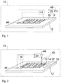
- FIG. 1 shows a schematic, partial perspective view of a first embodiment of a vehicle heater 10, and it also illustrates the monitoring process.
- vehicle heater 10 as well as in all other vehicle heaters described below may be both air heaters and so-called water heaters, for example - and without being limited to - for electric or hybrid cars.
- Air heaters differ from the so-called water heaters in that in air heaters to be heated air flow is passed directly through a heat exchanger of the air heater, while at The so-called water heaters first a liquid, usually a mixture of water - hence the name - and an antifreeze, such as glycol, is passed through a heat exchanger of the water heater to the heat with the help of the liquid and another heat exchanger to the desired location bring.
- a liquid usually a mixture of water - hence the name - and an antifreeze, such as glycol
- Vehicle heater 10 which is shown only schematically as a block, has a main body 12, which in this case is a heat exchanger.
- this heat exchanger 12 is provided to heat air or a liquid, including the heat exchanger 12 may have on its underside unillustrated ribs or similar means for increasing the effective surface for the heat exchange.
- the surface of the heat exchanger 12 has been equipped with a non-intrinsically safe Schuetzmaschinen 14, by means of a thermal spraying process.
- the Schuleiter für 14 is connected to a voltage source, not shown, which may be, for example, an optionally down-pulsed by pulse width modulation to 250 volts DC source.
- the heat conductor layer at its end portions is suitable to contact, which is at the discretion of the skilled person and is also not shown.
- a sensor element 44 Adjacent to the heating conductor layer 14, a sensor element 44 is provided on the surface of the heat exchanger 12, which may be formed for example by a PTC or NTC sensor.
- the sensor element 44 is able to measure the temperature at its mounting location comparatively accurately, and to communicate the measured temperature to a controller 20.
- a sensor layer 16 was sprayed by means of a thermal spraying process, which in the case of the embodiment of FIG. 1 has a positive temperature coefficient, so that at least a PTC characteristic results for the sensor layer 16 at least.
- thermal spraying method may possibly lead to a configuration instead of the schematically shown exact sandwich-type layer structure in which the material of the sensor layer 16 extends at least in sections over the edge regions of the heating conductor layer 14 or in the case of the heating conductor layer 14 even more or less completely buried under the sensor layer 16.
- the electrical conductivity of the sensor layer 16 for normal operating temperatures must be chosen lower than the electrical conductivity of the Schuleitertik 14 to ensure proper operation of the vehicle heater 10.
- the measuring device 18 monitors the temperature-dependent resistance of the sensor layer 16, for example by applying a preferably constant voltage to the end sections of the sensor layer 16 as indicated by the dashed lines and detecting the resulting current flow, for example via a shunt resistor. may be part of the measuring device 18. Occurs now in the heat conductor layer 14, for example, due to a smoldering or arc ignition a local but very strong overheating to, for example, 1000 ° C, this leads to a suitable conditioning of the sensor layer 16 that their total resistance so dominated by their positive temperature coefficient series circuit nature increases that this can be reliably detected by the measuring device 18.
- the sensor element 44, the sensor layer 16, the measuring device 18 and a controller 20 together form a temperature monitoring device which is able to distinguish the three following states and report them as signal 46: normal operation, reversible malfunction and irreversible malfunction. For example, if the sensor element 44 indicates a normal temperature in the range up to 150 ° C., the controller assumes normal operation and reports a corresponding signal 46. If the sensor element 44 reports, for example, an unauthorized temperature rise to 180 ° C., the controller assumes a reversible Malfunction and reports a corresponding signal 46. Such a reversible malfunction could be caused in the case of a water or liquid heating, for example, by missing or standing liquid.
- the controller 20 switches in one In such case, the heat conductor layer 14 temporarily from or at least reduces the heating power. As soon as the sensor element 44 again reports a normal temperature, the heating power can usually be increased again. Preferably, regardless of what the sensor element 44 is currently reporting, the controller 20 assumes an irreversible malfunction if the measuring device 18 has also reported a very high overheating detected by the sensor layer 16 in the area of the heating conductor layer 14 only once. Thus, the signal of the measuring device 18 preferably has priority over the signal of the sensor element 44, because a strong local overheating in any area of the heating conductor layer 14 may not even affect the mounting location of the sensor element 44.
- the controller 20 generates any suitable signal 46 indicative of an irreversible malfunction, preventing re-startup.
- the controller 20 does not have to be exclusively associated with the monitoring device. For example, it is conceivable that the controller 20 controls or regulates the operation of the entire vehicle heating, or that the functions essential for the monitoring device are detected by a controller 20, which is already present in the vehicle anyway.
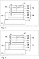
- FIG. 2 shows a schematic, partial perspective view of a second embodiment of a vehicle heater 10, and it also illustrates the monitoring process.
- the heat conductor layer 14 is sprayed directly onto the body formed by a heat exchanger 12 of the vehicle heater 10.
- the vehicle heating according to FIG. 2 differs from the vehicle heater accordingly FIG. 1 in that the sensor layer 16 in this embodiment comprises three components. Namely, the heat conductor layer 14, which forms a component of the sensor layer 16 in this case, in addition to their actual function as a heating element.
- the measuring device 18 is connected in this case, as indicated by the dashed lines, between the additionally serving as the lower contact layer Schuleiter Anlagen 14 and over the layer 22 provided with a negative temperature coefficient contact layer 24.
- the measuring device 18 can so, in a similar manner as in the context of the embodiment according to FIG. 1 has been explained, reliably detect an irreversible malfunction and provide the controller 20 with a corresponding signal.
- FIG. 3 shows a schematic, partially sectional view of a third embodiment of a vehicle heater, which simultaneously illustrates the monitoring process.
- the embodiment according to FIG. 3 differs from the embodiment according to FIG. 2 in that the heat exchanger 10 in this case consists of an electrically conductive material, in particular of aluminum. Therefore, in this embodiment, the heating conductor layer 14 is subdivided into a first insulation layer 26, the actual heating layer 28 and a second insulation layer 30. Preferably, all three components of the heating conductor layer are sprayed by a thermal spraying method. Based on the illustration above of the total designated 14 Thompsonleiter für, a generally designated 16 sensor layer is provided, which was also sprayed by a thermal spray process and in turn having three components in this embodiment. Directly above the second insulation layer 30 is a first electrically conductive contact layer 32 onto which a layer 34 of a material having a negative temperature coefficient has been sprayed.
- the layer 34 may be, but is not limited to, in particular, one of the materials proposed in the general part of the description for negative temperature coefficient layers.
- a second upper electrically conductive contact layer 36 was injected.
- a smoldering point leads to such a strong local heating that it can be detected by tapping off the measuring signal between the upper contact layer 36 and the lower contact layer 32 via a measuring device 18, as shown in FIG FIG. 2 is shown.
- an electrically conductive gas channel 38 is located, such as it arises in the case of an arc ignition starting from the actual heating layer 28.
- the gas channel 38 penetrates or penetrates the remaining layers on the side facing away from the base body of the Edelleiter Mrs 14 and leads to a current flow through the layer 34 with a negative temperature coefficient, in the direction of their surface normal 42. This current flow can through a between the lower contact layer 32nd and the upper contact layer 36 switched measuring device are detected.
- FIG. 4 shows a schematic, partially sectional view of a fourth embodiment of a vehicle heater, which also illustrates the monitoring process.
- FIG. 4 illustrated embodiment differs from the embodiment according to FIG. 3 in that the sensor layer 16 instead of the in FIG. 3 a negative temperature coefficient layer 34 comprises an insulating layer 40.
- the sensor layer 16 instead of the in FIG. 3 a negative temperature coefficient layer 34 comprises an insulating layer 40.
- a negative temperature coefficient layer 34 comprises an insulating layer 40.
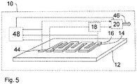
- FIG. 5 shows a schematic, partial perspective view of a fifth embodiment of a vehicle heater, which also illustrates the monitoring process.
- the temperature monitoring device 16, 18, 20, 44, 48 includes a software-programmable or operable controller 20 and independent of the software operating circuit components 48.
- These circuit components 48 are designed to in the case of the occurrence of at least one of the present invention to be distinguished functional disorders to carry out an emergency measure software independent.
- an emergency measure may in particular be the reduction of the heating power, for example the power supply to the heating conductor layer 14 may be completely or partially prevented by the opening of a transistor or other semiconductor switch (not shown) belonging to the circuit components.
- the circuit components 48 may, for example, comprise one or more operational amplifiers serving for comparison purposes, which compare measured values or tapped voltages supplied by the sensors with values or voltages supplied by reference voltage sources so as to be able to detect at least one of the states to be distinguished according to the invention. This is in FIG. 5 indicated by the corresponding input signals of the circuit components 48 shown only schematically.
- the circuit components 48 are further capable of providing the controller 20 with a signal (eg, a particular voltage value) in the event of a malfunction, such that the controller 20 may perform the memory function preferred in the present invention.
- the circuit components 48 may include functions that the controller 20 or the measuring device 18 in the embodiment according to FIG. 1 take over, either redundantly or exclusively make available. In any case, the circuit components 48 result in a certain software independence, which may be desirable in particular for (strongly) safety-relevant functions.
- the respective sensor layers 16 are preferably applied to the base body 12 by a thermal spraying process.
- the respective sensor layer 16 is produced as a separate component and then fixed on the heating conductor layer 14, for example by clamping, gluing or thermal bonding with heat conducting foil. If the sensor or the sensor layer 16 are produced as a separate component, it is of course also in the case of heat-sensitive bodies possible to use for producing the sensor layer 16 conventional baking or high-melting and / or non-injectable materials.
- the above-mentioned insulating layers 26, 30 and 40 may, for example, be aluminum oxide layers, while the heating conductor layer 14 or the actual heating layer 28 may be realized, for example, by a nickel-chromium layer.
- As contact layers 32, 36 may serve as copper layers, for example, and as a layer 34 with a negative temperature coefficient in addition to the already mentioned in the general part of the description materials, for example, a layer of doped with chromium oxide titanium into consideration.
Description
Die Erfindung betrifft eine Fahrzeugheizung mit einem Grundkörper, der eine nicht-eigensichere Heizleiterschicht trägt, wobei der Heizleiterschicht eine Temperaturüberwachungseinrichtung zugeordnet ist.The invention relates to a vehicle heater having a base body, which carries a non-intrinsically safe Heizleiterschicht, wherein the Heizleiterschicht is associated with a temperature monitoring device.
Weiterhin betrifft die Erfindung ein Verfahren zur Überwachung einer Fahrzeugheizung.Furthermore, the invention relates to a method for monitoring a vehicle heating.
Bei dem Grundkörper kann es sich in beiden Fällen beispielsweise um einen Wärmetauscher handeln, insbesondere um einen Metall/Luft- und/oder einen Metall/Flüssigkeit-Wärmetauscher.In both cases, the main body can be, for example, a heat exchanger, in particular a metal / air and / or a metal / liquid heat exchanger.
Im Gegensatz zu eigensicheren Heizleiterschichten, beispielsweise PTC-Heizleiterschichten, die einen zu starken Temperaturanstieg durch eine Begrenzung des Stromflusses selbstständig verhindern können, sind hier mit nicht-eigensicheren Heizleiterschichten alle Arten von Heizleiterschichten gemeint, die genau diese Fähigkeit zur Vermeidung von unsicheren Zuständen im Fehlerfall nicht aufweisen.In contrast to intrinsically safe heat conductor layers, such as PTC heat conductor layers, which can prevent excessive temperature increase by limiting the flow of current, non-intrinsically safe Heizleiterschichten here all types of Heizleiterschichten meant that precisely this ability to avoid unsafe conditions in case of failure not exhibit.
Die nicht-eigensichere Heizleiterschicht kann, ohne darauf beschränkt zu sein, beispielsweise dazu vorgesehen sein, mit vergleichsweise hohen Spannungen beaufschlagt zu werden (beispielsweise 250 Volt Gleichspannung), wobei zu hohe Spannungen beispielsweise durch eine Pulsweitenmodulation heruntergetaktet werden können, wenn dies vorteilhaft erscheint. Solche im Vergleich zu konventionellen Bordnetzen mit 12 oder 24 Volt relativ hohen Spannungen stehen beispielsweise bei Elektro- oder Hybridfahrzeugen häufig ohnehin zur Verfügung. Beispielsweise in solchen Umgebungen lassen sich durchaus elektrische Fahrzeugheizungen mit einer Leistung im Bereich von drei bis acht Kilowatt betreiben, wobei der Anwendungsbereich der Erfindung jedoch keinesfalls auf diesen Leistungsbereich oder diese Fahrzeugtypen beschränkt ist.The non-intrinsically safe heating conductor layer may be, for example, but not limited to be subjected to relatively high voltages (for example, 250 volts DC), too high voltages can be clocked down, for example by a pulse width modulation, if this appears advantageous. Such compared to conventional 12 or 24 volt electrical systems relatively high voltages are often available, for example, in electric or hybrid vehicles anyway. For example, in such environments, electric vehicle heaters with a power in the range of three to eight kilowatts can certainly operate, but the scope of the invention is by no means limited to this power range or these vehicle types.
Eine Fahrzeugheizung mit einer Heizleiterschicht in Form eines nicht-eigensicheren Heizelementes ist beispielsweise aus der
Ferner, ist eine Fahrzeugheizung gemäß dem Oberbegriff des Anspruchs 1 aus
Der Erfindung liegt die Aufgabe zugrunde, die gattungsgemäßen Fahrzeugheizungen und die gattungsgemäßen Verfahren zur Überwachung einer Fahrzeugheizung so weiterzubilden, dass die Sicherheit erhöht wird.The invention has the object of developing the generic vehicle heaters and the generic method for monitoring a vehicle heating so that the security is increased.
Diese Aufgabe wird durch die Merkmale der unabhängigen Ansprüche gelöst. Vorteilhafte Ausgestaltungen und Weiterbildungen der Erfindung ergeben sich aus den abhängigen Ansprüchen.This object is solved by the features of the independent claims. Advantageous embodiments and modifications of the invention will become apparent from the dependent claims.
Vorgeschlagen wird zunächst eine Fahrzeugheizung mit einem Grundkörper, der eine nicht-eigensichere Heizleiterschicht trägt, wobei der Heizleiterschicht eine Temperaturüberwachungseinrichtung zugeordnet ist. Die Temperaturüberwachungseinrichtung ist dabei dazu ausgelegt, zumindest die drei folgenden Zustände zu unterscheiden und als Signal zu melden: Normalbetrieb, reversible Funktionsstörung und irreversible Funktionsstörung. Von einem Normalbetrieb der Fahrzeugheizung kann beispielsweise bei einer Temperatur bis zu 150 °C ausgegangen werden. Bei einer reversiblen Funktionsstörung, die im Falle eines Wasser- oder Flüssigkeitsheizgerätes beispielsweise durch fehlende oder stehende Flüssigkeit verursacht werden kann, steigt die Temperatur über den beispielhaft genannten Wert von 150 °C an, so dass beispielsweise beim Erreichen einer Temperatur von 180 °C eine temporäre Abschaltung der Heizleiterschicht oder zumindest eine Leistungsreduzierung erfolgen kann. Eine irreversible Funktionsstörung kann beispielsweise vorliegen, wenn es in sehr seltenen Fällen zu einem Glimmpunkt oder einer Lichtbogenzündung gekommen ist. Solche seltenen Ereignisse führen in der Regel zwar nur zu lokalen, dafür aber extrem starken Überhitzungen, bei denen beispielsweise Temperaturen im Bereich von 1000 °C erreicht werden können. Durch die Unterscheidung der drei genannten Zustände ist es beispielsweise möglich, den zuletzt gemeldeten Zustand vor einer erneuten Inbetriebnahme, also einem neuen Betriebszyklus der Fahrzeugheizung abzufragen und im Falle einer irreversiblen Funktionsstörung eine erneute Inbetriebnahme zu verhindern, so dass die Fahrzeugheizung in einem solchen Fall dauerhaft abgeschaltet bleibt, solange kein Austausch oder keine Reparatur erfolgt ist. Die Sicherheit wird dadurch maßgeblich erhöht, weil insbesondere irreversible Fehler bei einem erneuten Einschalten des Heizgerätes zu einer erneuten sehr starken zumindest lokalen Überhitzung führen können.First proposed is a vehicle heater with a base body, which carries a non-intrinsically safe Heizleiterschicht, wherein the Heizleiterschicht is associated with a temperature monitoring device. The temperature monitoring device is designed to distinguish at least the three following states and report them as a signal: normal operation, reversible malfunction and irreversible malfunction. From a normal operation of the vehicle heating can be assumed, for example, at a temperature up to 150 ° C. In the case of a reversible malfunction, which may be caused, for example, by missing or standing liquid in the case of a water or liquid heater, the temperature rises above the exemplified value of 150 ° C, so that, for example, when reaching a temperature of 180 ° C a temporary Shutdown of the heat conductor layer or at least a reduction in power can take place. An irreversible malfunction may be present, for example, when in very rare cases a smoldering point or an arc ignition has occurred. Although such rare events usually lead only to local, but extremely strong overheating, in which, for example, temperatures in the range of 1000 ° C can be achieved. By distinguishing the three states mentioned, it is possible, for example, to query the last reported state before restarting, ie a new operating cycle of the vehicle heater, and to prevent restarting in the event of an irreversible malfunction, so that the vehicle heater is permanently switched off in such a case remains as long as no replacement or repair has taken place. The security is significantly increased because in particular irreversible errors in a renewed switching on the heater can lead to a renewed very strong at least local overheating.
Bei der Fahrzeugheizung kann vorgesehen sein, dass die Temperaturüberwachungseinrichtung zur Detektion von reversiblen Funktionsstörungen ein lokale Temperaturen erfassendes Sensorelement umfasst. Bei diesem Sensorelement kann es sich beispielsweise um ein herkömmliches PTC- oder NTC-Sensorelement handeln. Solche Sensorelemente sind in der Lage, die lokalen Temperaturen sehr genau zu erfassen, teilweise bis auf wenige °C genau. Sie eignen sich daher beispielsweise besonders gut, den oben beispielhaft genannten Temperaturanstieg von 150 °C auf 180 °C zu detektieren.In the case of vehicle heating, provision may be made for the temperature monitoring device to include a sensor element detecting local temperatures for detecting reversible malfunctions. This sensor element may be, for example, a conventional PTC or NTC sensor element. Such sensor elements are able to detect the local temperatures very accurately, sometimes up to a few ° C exactly. They are therefore particularly suitable, for example, to detect the temperature increase from 150 ° C. to 180 ° C. mentioned above by way of example.
Weiterhin ist es möglich, dass die Temperaturüberwachungseinrichtung zur Detektion von irreversiblen Funktionsstörungen eine der Heizleiterschicht zumindest abschnittsweise zugeordnete Sensorschicht umfasst. Diese Sensorschicht ist dann vorzugsweise zumindest in der Lage, lokale und sehr starke Überhitzungen der Heizleiterschicht sicher und schnell zu detektieren, wie sie beispielsweise im Falle der erwähnten Glimmpunkte oder Lichtbögen auftreten. Die Sensorschicht ist dabei vorzugsweise über oder unter der Heizleiterschicht angeordnet. Beispielsweise kann die Sensorschicht die Heizleiterschicht mehr oder weniger vollständig abdecken (Anschlussbereiche und dergleichen können gegebenenfalls ausgespart werden). Da es sich bei einer Sensorschicht immer im weitesten Sinne um eine zumindest abschnittsweise flächige Schicht handelt, kommt beispielsweise auch eine aus einem oder mehreren (ggf. sehr schmalen) Streifen bestehende Sensorschicht in Betracht. Die Sensorschicht kann dabei einer beispielsweise mäanderförmig angeordneten Heizleiterschicht vom Verlauf her folgen, wobei sie die Heizleiterschicht aber vorzugsweise vollständig überdeckt (Anschlussbereiche können wie erwähnt gegebenenfalls ausgespart werden), oder die Sensorschicht kann größere Bereiche des Grundkörpers abdecken. Beispielsweise kann die Sensorschicht als in der Draufsicht rechteckige Sensorschicht über eine mäanderförmige Heizleiterschicht gelegt werden. Dabei kommen sowohl Lösungen in Betracht, bei denen die Sensorschicht direkt über der Heizleiterschicht angeordnet ist, so dass die Sensorschicht die Heizleiterschicht also zumindest abschnittsweise berührt, als auch Lösungen, bei denen zumindest eine Zwischenschicht vorgesehen ist. Als besonders wirksam hat es sich erwiesen, wenn die Sensorschicht so konditioniert ist, dass sie ihren Widerstand oder ihre Impedanz bereits im Falle einer lokalen Überhitzung stark ändert. Mit Hilfe einer solchen flächigen Sensorschicht ist es beispielsweise möglich eine lokale Überhitzung sicher zu detektieren, bevor das oben erwähnte Sensorelement an seinem Montageort eine lokale Temperaturerhöhung detektieren kann.Furthermore, it is possible that the temperature monitoring device for detecting irreversible malfunctions comprises a sensor layer at least partially associated with the heat conductor layer. This sensor layer is then preferably at least able to reliably and quickly detect local and very strong overheating of the heat conductor layer, as they occur, for example, in the case of the mentioned smoldering points or arcs. The sensor layer is preferably arranged above or below the heat conductor layer. For example, the sensor layer can cover the heat conductor layer more or less completely (connection areas and the like can optionally be omitted). Since a sensor layer is always an at least partially flat layer in the broadest sense, for example, a sensor layer consisting of one or more (possibly very narrow) strips can also be considered. In this case, the sensor layer can follow a heating conductor layer arranged in a meandering pattern, for example, but it preferably completely covers the heating conductor layer (connection areas may, as mentioned, if appropriate be omitted), or the sensor layer can cover larger areas of the body. By way of example, the sensor layer can be laid over a meander-shaped heating conductor layer as a sensor layer which is rectangular in plan view. In this case, both solutions come into consideration, in which the sensor layer is arranged directly above the heating conductor layer, so that the sensor layer thus at least partially contacts the heating conductor layer, as well as solutions in which at least one intermediate layer is provided. It has proven to be particularly effective if the sensor layer is conditioned in such a way that it already strongly changes its resistance or its impedance in the case of local overheating. With the aid of such a planar sensor layer, it is possible, for example, to reliably detect a local overheating before the above-mentioned sensor element can detect a local temperature increase at its installation location.
Zumindest in einigen Fällen wird es als vorteilhaft erachtet, dass die Sensorschicht mit Hilfe eines thermischen Spritzverfahrens ausgebildet wurde. Als Spritzverfahren kommen insbesondere thermische Spritzverfahren in Frage. Durch den Einsatz von thermischen Spritzverfahren können Sensorschichten hergestellt werden, ohne dass der Grundkörper den für Einbrennprozesse üblichen Temperaturen ausgesetzt wird. Ein derartiges Aufspritzen von Sensorschichten lässt sich vergleichbar günstig wie Einbrennverfahren durchführen, es schränkt jedoch die Anforderungen an die Temperaturverträglichkeit des verwendeten Grundkörpers (beziehungsweise an die von dem Grundkörper bereits getragenen Materialien) deutlich weniger ein. Daher kommen durch den Einsatz eines Aufspritzverfahrens für den Grundkörper auch Materialien in Frage, die bei für Einbrennprozesse üblichen Temperaturen schmelzen oder in ihrer Materialeigenschaft hinsichtlich des vorgesehenen Einsatzzweckes irgendwie anders negativ verändert würden. Beispielsweise kann der Grundkörper durch die Verwendung eines geeigneten Aufspritzverfahrens ganz oder teilweise aus Aluminium bestehen. Selbstverständlich kommt für den Grundkörper auch eine Vielzahl anderer Materialien in Frage, wobei es sich in vielen Fällen um Materialien mit guten Wärmeleiteigenschaften handeln wird. Lediglich beispielhaft seien in diesem Zusammenhang Aluminiumlegierungen, Gläser und Keramiken genannt. Als Beispiele für in Frage kommende thermische Spritzverfahren seien Plasmaspritzverfahren, Kaltgasspritzverfahren oder Flammspritzverfahren genannt. In einigen Fällen kann es vorteilhaft sein, auch andere Bestandteile der Fahrzeugheizung, beispielsweise die Heizleiterschicht, durch ein thermisches Spritzverfahren auszubilden. Als besonders gut geeignete thermische Spritzverfahren werden derzeit Kaltgasplasmaspritzverfahren und Suspensionsflammspritzverfahren betrachtet. Beim Kaltgasspritzen wird ein Gas, beispielsweise Stickstoff, auf hohe Geschwindigkeiten beschleunigt, wobei mit dem Gas beförderte Partikel mit hoher Geschwindigkeit (beispielsweise mehrfacher Schallgeschwindigkeit) auf den Grundkörper oder ein von diesem getragenes Substrat auftreffen und durch die hohe kinetische Energie eine dichte, fest haftende Schicht bilden. Beim Suspensionsflammspritzen wird zunächst eine Suspension mit den aufzuspritzenden Partikeln hergestellt, um diese Suspension dann in eine Flamme einzudüsen. Dabei verdampft die Flüssigkeit zumindest teilweise, vorzugsweise aber ganz, und es treffen (idealerweise) nur die jeweiligen Partikel auf die Zieloberfläche auf, wodurch sich dichte Schichten herstellen lassen. Jedenfalls ist den in Frage kommenden Verfahren zum Aufspritzen der Sensorschicht gemeinsam, dass der Grundkörper dabei nicht den für Einbrennverfahren üblichen hohen Temperaturen ausgesetzt werden muss. In diesem Zusammenhang kann beispielsweise vorgesehen sein, dass der Grundkörper nur Temperaturen von weniger als 800 °C, weniger als 650 °C und sogar nur weniger als 500 °C ausgesetzt wird. Es ist nachvollziehbar, dass die für den Grundkörper (und/oder irgendwelche von diesem bereits getragenen Komponenten) verwendbare Anzahl von Materialien steigt, je niedriger die Temperaturen gehalten werden können. Dabei sollte klar sein, dass die Formulierung "Temperaturen ausgesetzt wird" nicht zwingend bedeuten soll, dass der gesamte Grundkörper diese Temperatur dadurch annehmen soll oder muss. Vielmehr kommt es ausschließlich darauf an, dass der Grundkörper auch nicht abschnittsweise Temperaturen ausgesetzt wird, durch die er Schaden nehmen könnte. Je nach Beschaffenheit des Grundkörpers (Größe, Wärmeleitfähigkeit, usw.) kann es daher beispielsweise in einigen Fällen durchaus möglich sein, dass der Grundkörper in den dem Aufspritzvorgang nicht direkt ausgesetzten Bereichen bereits Komponenten (beispielsweise elektrische oder andere Bauteile) trägt, die nur sehr viel niedrigeren Temperaturen als 500 °C widerstehen können, beispielsweise nur 100 °C oder noch weniger. Es kann vorgesehen sein, dass die Sensorschicht mit Hilfe eines Pulvers hergestellt wird, wobei Pulverpartikel des Pulvers in agglomerierter Form vorliegen oder in agglomerierte Form gebracht werden und wobei die nicht-agglomerierten Pulverpartikel eine mittlere Korngröße d50 von weniger als 20 µm, vorzugsweise weniger als 10 µm aufweisen. Bezüglich der hier gemeinten, üblichen Definition der mittleren Korngröße d50 wird auf die einschlägige ISO 9276-2 verwiesen, sofern diesbezüglich Erläuterungsbedarf bestehen sollte. Beispielsweise Bariumtitanat-Pulver, das in einigen Fällen zur Schaffung der Sensorschicht in Frage kommen kann, hat typischerweise eine Kristallgröße von weniger als 10 µm (beispielsweise zwischen 2 µm und 8 µm oder zwischen 4 µm und 5 µm). Diese Partikelgröße kann für manche thermische Spritzverfahren (wie beispielsweise Plasmaspritzverfahren) zu klein sein, da sie zu Verstopfungen von Öffnungen des bei diesen Verfahren eingesetzten Spritzbrenners (oder irgendeines anderen Bestandteils der zum Aufspritzen verwendeten Vorrichtung) führen kann. Liegen jedoch mehrere Pulverpartikel in agglomerierter Form vor, zum Beispiel eingebettet in ein Hüllmaterial, kann ein Verstopfen der Öffnungen des Spritzbrenners vermieden werden. In den Agglomeraten können jeweils mehrere Pulverpartikel mit dem Hüllmaterial verbunden sein, das beispielsweise einen Kunststoff wie Polyvinylalkohol als Bestandteil haben kann. Weil die Agglomerate zumindest in der überwiegenden Mehrzahl größer als einzelne Pulverpartikel sind, kann ein Verstopfen des Spritzbrenners (oder irgendeines anderen Bestandteils der zum Aufspritzen verwendeten Vorrichtung) so zumindest in vielen Fällen vermieden werden. Selbstverständlich ist die Herstellung und Verwendung von Agglomeraten nicht auf Bariumtitanat-Pulver beschränkt. Vielmehr kann diese Technik für jedes im Rahmen der Erfindung in Frage kommende Pulver mit zu kleinen Pulverpartikeln verwendet werden. Damit die aufgespritzte Sensorschicht insgesamt die gewünschten elektrischen (oder optischen oder sonstigen) Eigenschaften aufweist, kann es sinnvoll sein, das zur Bildung der Agglomerate verwendete Hüllmaterial geeignet zu konditionieren. Soll beispielsweise insgesamt eine bestimmte spezifische elektrische Leitfähigkeit erzielt werden, sollte das Hüllmaterial vorzugsweise eine spezifische elektrische Leitfähigkeit haben, die in etwa mindestens so groß ist, wie die spezifische elektrische Leitfähigkeit der Pulverpartikel (bei einer Normalbetriebstemperatur der Fahrzeugheizung), sofern die Agglomerate beim Aufspritzen nicht zerstört werden oder das Hüllmaterial zumindest teilweise Bestandteil der aufgespritzten Sensorschicht bleibt. Man kann ein Zerstören der Agglomerate beziehungsweise ein zumindest teilweises Entfernen des Hüllmaterials aber auch gezielt unterstützen, so dass die Eigenschaften der Sensorschicht (zumindest weitgehend) durch die Eigenschaft der Pulverpartikel bestimmt werden. Hierzu können geeignete thermische, chemische und/oder physikalische Prozesse oder Nachbehandlungsschritte durchgeführt werden, sobald die Agglomerate die zur Verstopfung neigenden Abschnitte passiert haben. Falls mehrere Pulverkörner erst in die agglomerierte Form gebracht werden müssen, kann hierzu beispielsweise folgendermaßen vorgegangen werden: In einem ersten Schritt kann das entsprechende Material in seiner ursprünglichen Beschaffenheit bereitgestellt werden. In einem zweiten Schritt erfolgt dann eine Umwandlung in ein Vollmaterial, insbesondere mittels Sintern. Anschließend wird das Vollmaterial mittels Zerkleinern des Vollmaterials pulverisiert. Daraufhin können die Pulverpartikel durch die Anwendung eines Bindersystems sowie eine nachfolgende Trocknung und ein Ausbrennen des Binders agglomeriert werden. Es ist ebenfalls möglich, die Pulverpartikel mit Hilfe eines Granulierverfahrens zu pulverisieren. Soll beispielsweise ein granuliertes Perowskitpulver mit einer vorbestimmten mittleren Korngröße d50 zum Einsatz kommen, so kann wie folgt vorgegangen werden: In einer ersten Verfahrensstufe erfolgt ein Einwiegen und Mischen, ein Lösen der Salze in Säure, ein Ausfällen mit Lauge, ein Filtrieren sowie ein Waschen und Trocknen. In einer zweiten Verfahrensstufe kann anschließend eine Wärmebehandlung zur Phasenreaktion und/oder Umwandlung durchgeführt werden. In einer dritten Verfahrensstufe kann dann ein Nassmahlen bis zur gewünschten Feinheit erfolgen, wobei in einer vierten Verfahrensstufe ein Fraktionieren durch Sichten oder Sieben, eine Kontrolle des fertigen Pulvermaterials und/oder eine Aufbereitung von Restmengen erfolgen kann. Insbesondere in Fällen, in denen der Grundkörper und von diesem eventuell schon getragene Komponenten eine ausreichende Wärmefestigkeit aufweisen, können alternativ natürlich auch die gängigen Einbrennverfahren angewendet werden, um die Sensorschicht (oder andere Schichten) auszubilden.At least in some cases it is considered advantageous that the sensor layer has been formed by means of a thermal spraying process. In particular, thermal spraying methods are suitable as spraying methods. Through the use of thermal spraying sensor layers can be produced without the body is exposed to the usual temperatures for baking processes. Such spraying of sensor layers can be performed comparably favorably as baking process, but it limits the requirements for the temperature compatibility of the base body used (or to the already carried by the body materials) significantly less. Therefore come through the use of a spray-on for the body also materials in question, which would melt at usual for baking processes temperatures or any other negative change in their material properties with regard to the intended use. For example, the main body can consist entirely or partially of aluminum by using a suitable spray-on process. Of course, a variety of other materials come into question for the body, which in many cases will be materials with good thermal conductivity properties. By way of example only aluminum alloys, glasses and ceramics are mentioned in this context. Examples of suitable thermal spray processes are plasma spraying, cold spraying or flame spraying. In some cases, it may be advantageous to form other components of the vehicle heater, such as the heat conductor layer, by a thermal spray process. Cold spray plasma spraying and suspension flame spraying are currently considered to be particularly suitable thermal spray processes. During cold gas spraying For example, a gas, such as nitrogen, is accelerated to high velocities, with particles carried by the gas striking the body or a substrate carried thereon at high speed (eg, multiple sound velocities) and forming a dense, adherent layer by the high kinetic energy. In suspension flame spraying, a suspension with the particles to be sprayed on is first prepared in order to then inject this suspension into a flame. The liquid evaporates at least partially, but preferably completely, and (ideally) only the respective particles strike the target surface, which makes it possible to produce dense layers. In any case, the method in question for spraying the sensor layer has in common that the base body does not have to be exposed to the usual high temperatures for baking processes. In this context, it may be provided, for example, that the base body is only exposed to temperatures of less than 800 ° C, less than 650 ° C and even less than 500 ° C. It will be appreciated that the lower the temperatures that can be maintained, the greater the usefulness of the body (and / or any components already carried by it) increases. It should be clear that the phrase "exposure to temperatures" should not necessarily mean that the entire body should or must accept this temperature. Rather, it is only important that the body is not partially exposed to temperatures that could damage it. Depending on the nature of the body (size, thermal conductivity, etc.), it may therefore be possible, for example, in some cases, that the base body already carries components (for example, electrical or other components) in the areas not directly exposed to the spraying process, which only very much lower temperatures than 500 ° C can withstand, for example, only 100 ° C or even less. It can be provided that the sensor layer is produced by means of a powder, wherein powder particles of the powder are present in agglomerated form or are brought into agglomerated form and wherein the non-agglomerated powder particles have an average particle size d50 of less than 20 .mu.m, preferably less than 10 have μm. With regard to the customary definition of mean particle size d50 referred to here, reference is made to the relevant ISO 9276-2, insofar as there is a need for clarification in this regard. For example, barium titanate powder, which in some cases can be used to create the sensor layer, typically has a crystal size of less than 10 microns (for example, between 2 microns and 8 microns or between 4 microns and 5 microns). This particle size may be too small for some thermal spraying processes (such as plasma spraying processes), as they cause clogging of orifices of the spray gun used in these processes (or any other component of the device used for spraying). However, if several powder particles in agglomerated form, for example embedded in a shell material, clogging of the openings of the spray burner can be avoided. In the agglomerates in each case a plurality of powder particles may be connected to the shell material, which may for example have a plastic such as polyvinyl alcohol as an ingredient. Because the agglomerates are at least predominantly larger than individual powder particles, clogging of the spray gun (or any other component of the device used for spraying) can thus be avoided, at least in many cases. Of course, the production and use of agglomerates is not limited to barium titanate powders. Rather, this technique can be used for any in the invention in question in question powder with too small powder particles. In order for the sprayed-on sensor layer as a whole to have the desired electrical (or optical or other) properties, it may be useful to suitably condition the shell material used to form the agglomerates. If, for example, a certain specific electrical conductivity is to be achieved overall, the cladding material should preferably have a specific electrical conductivity which is at least as great as the specific electrical conductivity of the powder particles (at a normal operating temperature of the vehicle heating), unless the agglomerates during spraying be destroyed or the shell material at least partially remains part of the sprayed sensor layer. However, destroying the agglomerates or at least partially removing the cladding material can also be specifically supported so that the properties of the sensor layer are (at least largely) determined by the property of the powder particles. For this purpose, suitable thermal, chemical and / or physical processes or post-treatment steps can be carried out as soon as the agglomerates have passed the sections which are prone to clogging. If several powder grains must first be brought into the agglomerated form, this can be done, for example, as follows: In a first step, the corresponding material can be provided in its original state. In a second step, a conversion then takes place into a solid material, in particular by means of sintering. Subsequently, the solid material is pulverized by crushing the solid material. Subsequently, the powder particles can be agglomerated by the use of a binder system as well as subsequent drying and burn-out of the binder. It is also possible to pulverize the powder particles by means of a granulation process. If, for example, a granulated perovskite powder having a predetermined average particle size d50 is used, the procedure may be as follows: In a first process stage, weighing is carried out and mixing, dissolving the salts in acid, precipitation with caustic, filtering and washing and drying. In a second process stage, a heat treatment for phase reaction and / or conversion can then be carried out. In a third process stage, wet milling can then be carried out to the desired fineness, wherein in a fourth process stage fractionation by sifting or sieving, a check of the finished powder material and / or a treatment of residual amounts can take place. In particular, in cases in which the main body and possibly already carried by these components have sufficient heat resistance, of course, the conventional stoving can be applied, of course, to form the sensor layer (or other layers).
Es kann vorgesehen sein, dass die Sensorschicht zumindest bereichsweise eine Widerstands- beziehungsweise Impedanzcharakteristik mit einem positiven Temperaturkoeffizienten aufweist. Diese Herangehensweise ist insbesondere dann sinnvoll, wenn die Sensorschicht eine längliche Ausdehnung mit zwei Endabschnitten hat, zwischen denen ein Messsignal abgegriffen wird, um die Sensorschicht hinsichtlich in ihrer Längsrichtung auftretender (oder erzwungener) Ströme zu überwachen. Die Funktionsweise kann dann ähnlich wie bei der Verwendung eines PTC-Widerstandsleiters sein, weil aufgrund des Reihenschaltungscharakters einer solchen länglichen Ausdehnung bereits eine ausreichende Erwärmung eines vergleichsweise kurzen Längenabschnitts ausreicht, um den Gesamtwiderstand (beziehungsweise die Gesamtimpedanz) so weit zu erhöhen, dass eine lokale Temperaturschwellenwertüberschreitung sicher detektiert werden kann. Entlang größerer Längenabschnitte oder sogar über die gesamte Länge auftretende Temperaturschwellenwertüberschreitungen lassen sich so natürlich erst recht sicher feststellen. Ein Beispiel zur Erzielung einer Widerstandscharakteristik mit einem positiven Temperaturkoeffizienten ist die Verwendung des vorstehend schon erwähnten Bariumtitanat-Pulvers, wobei das relativ kostengünstige Bariumtitanat vorzugsweise mit Blei dotiert ist oder wird.It can be provided that the sensor layer at least partially has a resistance or impedance characteristic with a positive temperature coefficient. This approach is particularly useful when the sensor layer has an elongate extension with two end portions between which a measurement signal is tapped to monitor the sensor layer for currents occurring in its longitudinal direction (or forced). The operation may then be similar to the use of a PTC resistor ladder because, due to the series circuit nature of such an elongated extent, sufficient heating of a comparatively short length is sufficient to increase the total resistance (or total impedance) to a point where the temperature exceeds a local threshold can be reliably detected. Along larger lengths or even over the entire length occurring Temperaturschwellenwertüberschreitungen can be determined so certainly certainly. An example of obtaining a resistance characteristic with a positive temperature coefficient is the use of the above-mentioned barium titanate powder, wherein the relatively inexpensive barium titanate is or will be doped with lead.
Es ist aber auch möglich, dass die Sensorschicht zumindest bereichsweise eine Widerstands- beziehungsweise Impedanzcharakteristik mit einem negativen Temperaturkoeffizienten aufweist. Das Vorsehen eines negativen Temperaturkoeffizienten kommt insbesondere dann in Betracht, wenn es sich bei der Sensorschicht im weitesten Sinn um eine zumindest abschnittsweise flächige Schicht handelt, die hinsichtlich Stromflüssen in Richtung ihrer (ggf. jeweiligen) Flächennormalen überwacht werden soll. Als flächige Sensorschicht soll hierbei beispielsweise auch eine aus einem oder mehreren (ggf. sehr schmalen) Streifen bestehende Sensorschicht verstanden werden, beispielsweise auch eine aus Streifen bestehende Schicht, bei der der Streifen eine Zylinderoberfläche mehrfach und auf verschiedenen Höhen umschlingt, so dass sich eine Vielzahl von (differentiellen) Flächennormalen ergibt. In der Regel wird die Ober- und die Unterseite der Schicht mit negativem Temperaturkoeffizienten jeweils mit einer ebenfalls flächigen Elektrode zum Abgreifen eines Messsignals ausgestattet sein. Eine solche Sensorschicht kann als Parallelschaltung einer Vielzahl von Widerständen oder Impedanzen (Kapazitäten) betrachtet werden, so dass bereits eine lokale Temperaturschwellenwertüberschreitung zu einem sicher detektierbaren Sinken des Gesamtwiderstandes (beziehungsweise der Gesamtimpedanz) führt. Temperaturschwellenwertüberschreitungen, die größere Flächenabschnitte oder sogar die gesamte Fläche betreffen, lassen sich so natürlich ebenfalls sicher feststellen. Ebenso kann beispielsweise auch ein lokaler Durchschlag oder eine lokale Lichtbogenbildung zwischen den Elektroden festgestellt oder im Idealfall vorhergesehen und damit vermieden werden. Beispielsweise in Fällen, in denen es ausschließlich um die Detektion von Durchschlägen geht, kommen auch Ausführungsformen in Betracht, bei denen die Sensorschicht durch eine flächige Isolatorschicht mit auf der Ober- und der Unterseite davon vorgesehenen Kontaktschichten gebildet ist. Insofern ist der Begriff negativer Temperaturkoeffizient hier im weitesten Sinne zu verstehen. Um eine Sensorschicht mit negativem Temperaturkoeffizient im klassischeren Sinne auszubilden, können beispielsweise Materialien wir Siliziumdioxid, Siliziumcarbid, Aluminiumoxid, Titanoxid und andere Keramiken verwendet werden. Beispielsweise im Falle einer Glaskeramik kann vorgesehen sein, dass diese ein oder mehrere Alkalimetalle enthält, beispielsweise in einem Anteil bis zu zehn Gewichtsprozent. Es kann auch vorgesehen sein, dass die Glaskeramik mit Zirkonoxid, Zirkonsilikat, Quarz, Titanoxid und/oder Zinkoxid dotiert ist oder wird. Der Anteil der Dotierung kann dabei beispielsweise bis zu drei Gewichtsprozent betragen.But it is also possible that the sensor layer has at least partially a resistance or impedance characteristic with a negative temperature coefficient. The provision of a negative temperature coefficient comes into consideration, in particular, if the sensor layer in the broadest sense is an at least partially flat layer which is to be monitored with regard to current flows in the direction of its (possibly respective) surface normal. In this case, a flat sensor layer is to be understood as meaning, for example, a sensor layer consisting of one or more strips (possibly very narrow), for example also one Strip existing layer in which the strip wraps around a cylinder surface several times and at different heights, resulting in a plurality of (differential) surface normals. In general, the top and the bottom of the negative temperature coefficient layer will each be equipped with a likewise flat electrode for tapping a measuring signal. Such a sensor layer can be regarded as a parallel connection of a multiplicity of resistances or impedances (capacitances), so that even a local temperature threshold value overshoot leads to a reliably detectable decrease in the total resistance (or of the total impedance). Temperature threshold overruns that affect larger areas or even the entire area can of course also be determined with certainty. Likewise, for example, a local breakdown or a local arcing between the electrodes can be determined or, ideally, foreseen and thus avoided. For example, in cases where it is all about the detection of breakdowns, are also embodiments in which the sensor layer is formed by a sheet-like insulator layer provided on the top and the bottom thereof contact layers. In this respect, the term negative temperature coefficient is to be understood here in the broadest sense. For example, to form a sensor layer having a negative temperature coefficient in the more classical sense, materials such as silicon dioxide, silicon carbide, alumina, titanium oxide and other ceramics may be used. For example, in the case of a glass ceramic can be provided that this contains one or more alkali metals, for example in an amount up to ten percent by weight. It can also be provided that the glass ceramic is or is doped with zirconium oxide, zirconium silicate, quartz, titanium oxide and / or zinc oxide. The proportion of doping can be, for example, up to three percent by weight.
Es kann vorteilhaft sein, wenn die Temperaturüberwachungseinrichtung solange einen Normalbetrieb meldet, wie ein erster Temperaturschwellenwert nicht überschritten wird, der von der Temperatur eines zu erwärmenden Mediums abhängt. Im Falle einer Wasser- oder Flüssigkeitsheizung kann beispielsweise vorgesehen sein, dass bei einer Mediumstemperatur von beispielsweise - 40 °C ein Normalbetrieb angenommen wird, solange im Bereich der Fahrzeugheizung beispielsweise Temperaturen im Bereich von - 40 °C bis 100 °C gemessen werden, insbesondere durch das oben erwähnte Sensorelement. Liegt die Mediumstemperatur beispielsweise bei 75 °C, so kann beispielsweise solange ein Normalbetrieb angenommen werden, wie Temperaturen im Bereich von - 40 °C bis 150 °C gemessen werden.It may be advantageous if the temperature monitoring device as long as a normal operation reports, such as a first temperature threshold is not exceeded, which depends on the temperature of a medium to be heated. In the case of a water or liquid heating can be provided, for example, that at a medium temperature of for example - 40 ° C normal operation is assumed as long as in the field of vehicle heating, for example, temperatures in the range of - 40 ° C to 100 ° C are measured, in particular by the above-mentioned sensor element. If the medium temperature is, for example, 75 ° C., then, for example, normal operation can be assumed as long as temperatures in the range from -40 ° C. to 150 ° C. are measured.
Zumindest bei einigen Ausführungsformen der erfindungsgemäßen Fahrzeugheizung kann vorgesehen sein, dass die Temperaturüberwachungseinrichtung einen mit Software programmierbaren oder betreibbaren Controller und unabhängig von der Software arbeitende Schaltungskomponenten umfasst, die dazu ausgelegt sind, im Falle des Auftretens von zumindest einer der genannten Funktionsstörungen eine Notmaßnahme softwareunabhängig durchzuführen. Als Notmaßnahme kommt insbesondere eine Reduzierung der Heizleistung in Betracht, gegebenenfalls auf Null. Weiterhin können die Schaltungskomponenten dazu ausgelegt sein, dem Controller im Falle der Durchführung einer Notmaßnahme ein geeignetes Signal zu liefern, auf dessen Grundlage der Controller erkennt, dass die Schaltungskomponenten eine Funktionsstörung detektiert haben. Vorzugsweise wird dem Controller mit diesem Signal auch mitgeteilt, welche Art von Funktionsstörung (reversibel oder irreversibel) aufgetreten ist. Eine derartige Lösung kann aus Sicherheitsgründen in Erwägung gezogen werden, weil dadurch zumindest eine der Sicherheitsoptionen (zum Beispiel irreversibler Fehler, mittels flächigem Sensor detektiert) nicht oder nicht vollständig über eine Software, sondern ganz oder teilweise durch softwareunabhängige Hardware realisiert wird. Dadurch kann eine beispielsweise durch einen Softwarefehler hervorgerufene Fehlfunktion vermieden werden, weil sich eine gewisse Softwareunabhängigkeit ergibt. Die Schaltungskomponenten können dabei dazu ausgelegt sein, einen oder mehrere der erfindungsgemäß zu unterscheidenden Zustände zu detektieren. Dabei kommen Lösungen in Betracht, bei denen die Schaltungskomponenten redundant zu auch softwaremäßig verwirklichten Funktionen vorgesehen sind, oder auch Lösungen, bei denen durch die Schaltungskomponenten verwirklichte Funktionen softwaremäßig nicht zusätzlich verwirklicht werden. Wenn beispielsweise alle erfindungsgemäß zu unterscheidenden Zustände softwareunabhängig durch entsprechende Schaltungskomponenten detektiert werden können, ist es denkbar, dass alleine die erfindungsgemäß bevorzugte Merkfunktion, also das Verhindern eines erneuten Einschaltens aufgrund des Vorliegens eines bestimmten Signals, mit Hilfe des Controllers und entsprechender Software implementiert werden. Es ist aber auch denkbar, zu diesem Zweck softwareunabhängige aber merkfähige elektronische Bauteile einzusetzen, wobei unter merkfähig hierbei verstanden werden soll, dass auch eine Unterbrechung der Stromversorgung nicht dazu führt, dass eine auftretende Funktionsstörung später vergessen wird. Die Schaltungskomponenten können dabei Funktionen, wie vergleichen der Sensorwerte mit einem oder mehreren hardwaremäßig hinterlegten Werten und Abschalten (Notmaßnahme) bei Überschreiten des Wertes unter Einbeziehung beispielsweise eines Operationsverstärkers durchführen. Das Vorsehen derartiger Schaltungskomponenten kann nicht nur wegen schwer völlig auszuschließender Softwarefehler sinnvoll sein, sondern beispielsweise auch, wenn der softwaregestützte Controller noch für weitere Aufgaben verantwortlich ist, sodass er nicht immer oder nicht immer schnell genug zur Verfügung steht.At least in some embodiments of the vehicle heater according to the invention can be provided that the temperature monitoring device includes a software programmable or operable controller and independent of the software circuit components that are designed to perform an emergency measure software independent in the event of the occurrence of at least one of said malfunctions. As an emergency measure in particular a reduction of the heating capacity comes into consideration, if necessary to zero. Furthermore, the circuit components may be configured to provide the controller with a suitable signal upon the execution of an emergency measure, based on which the controller recognizes that the circuit components have detected a malfunction. Preferably, the controller is also informed with this signal which type of malfunction (reversible or irreversible) has occurred. Such a solution can be considered for security reasons, because at least one of the security options (for example, irreversible error, detected by flat sensor) is not or not completely implemented by software, but completely or partially by software-independent hardware. As a result, a malfunction caused, for example, by a software error can be avoided, because a certain software independence results. The circuit components can be designed to detect one or more of the states to be distinguished according to the invention. In this case, solutions may be considered in which the circuit components are provided redundantly to functions which are also realized in software, or also solutions in which functions realized by the circuit components are not additionally realized by software. If, for example, all the states to be differentiated according to the invention can be detected independently of software by means of corresponding circuit components, it is conceivable that only the inventively preferred memory function, ie the prevention of a renewed switch-on due to the presence of a specific signal, can be implemented with the aid of the controller and corresponding software. However, it is also conceivable to use software-independent but noticeable electronic components for this purpose, wherein it should be understood that the interruption of the power supply does not lead to a malfunction occurring being forgotten later. In this case, the circuit components can perform functions such as comparing the sensor values with one or more hardware-stored values and switching off (emergency measure) when the value is exceeded, including, for example, an operational amplifier. The provision of such circuit components can be meaningful not only because of hard to completely rule out software errors, but also, for example, if the Software-based controller is still responsible for other tasks, so it is not always or not always fast enough available.
Vorgeschlagen wird außerdem ein Verfahren zur Überwachung einer Fahrzeugheizung, bei dem die folgenden Zustände unterschieden und gemeldet werden: Normalbetrieb, reversible Funktionsstörung und irreversible Funktionsstörung. Dadurch ergeben sich die vorstehend im Zusammenhang mit der Fahrzeugheizung erläuterten Vorteile und Eigenschaften in analoger oder ähnlicher Weise, weshalb an dieser Stelle zur Vermeidung von Wiederholungen auf die entsprechenden Ausführungen im Zusammenhang mit der Fahrzeugheizung verwiesen wird.Also proposed is a method of monitoring a vehicle heater, which distinguishes and reports the following conditions: normal operation, reversible malfunction and irreversible malfunction. This results in the above explained in connection with the vehicle heating advantages and properties in an analogous or similar manner, which is why reference is made at this point to avoid repetition of the corresponding statements in connection with the vehicle heater.
Auch im Rahmen des Verfahrens kann vorgesehen sein, dass der Zustand einer reversiblen Funktionsstörung mit Hilfe eines lokale Temperaturen erfassenden Sensorelements festgestellt wird, wie dies oben bereits im Zusammenhang mit der Fahrzeugheizung erläutert wurde.It can also be provided within the scope of the method that the state of a reversible malfunction is detected with the aid of a sensor element detecting local temperatures, as has already been explained above in connection with the vehicle heating system.
Gleiches gilt für die Feststellung des Zustands einer irreversiblen Funktionsstörung mit Hilfe einer der Heizleiterschicht zumindest abschnittsweise zugeordneten Sensorschicht.The same applies to the determination of the state of an irreversible malfunction with the help of one of the Heizleiterschicht at least partially associated sensor layer.
Aus dem Vorstehenden ergibt sich, dass ein Grundgedanke der Erfindung darin besteht, ein nur lokal aber dafür genau messendes Sensorelement, beispielsweise einen PTC-oder NTC-Sensor, zur Feststellung eines Normalzustandes sowie zur Detektion von reversiblen Funktionsstörungen zu verwenden, die mit relativ geringen Abweichungen von Normaltemperaturen einhergehen. Gleichzeitig wird der Heizleiterschicht eine flächige Sensorschicht zugeordnet, die nicht unbedingt sehr genaue Messwerte liefern, aber dafür in der Lage sein muss, starke Überhitzungen, die an irgendeiner Stelle der Heizleiterschicht auftreten (beispielsweise verursacht durch Glimmpunkte oder Lichtbögen) schnell und sicher zu detektieren, auch wenn diese Überhitzungen von dem genaueren Sensorelement an seinem Montageort eventuell (noch) nicht erkannt werden können.From the above it follows that a basic idea of the invention is to use a sensor element which measures only locally but precisely, for example a PTC or NTC sensor, to determine a normal state and to detect reversible malfunctions which occur with relatively small deviations accompanied by normal temperatures. At the same time, the heat conductor layer is associated with a planar sensor layer, which may not necessarily provide very accurate readings, but must be able to quickly and safely detect strong overheating that occurs at any point on the heat conductor layer (eg, caused by smoldering or arcing) if these overheating may not (yet) be detected by the more accurate sensor element at its mounting location.
Die Erfindung wird nun unter Bezugnahme auf die beigefügten Zeichnungen anhand besonders bevorzugter Ausführungsformen beispielhaft erläutert.The invention will now be described by way of example with reference to the accompanying drawings by way of particularly preferred embodiments.
Es zeigen:
Figur 1- eine schematische, teilweise perspektivische Darstellung einer ersten Ausführungsform einer Fahrzeugheizung, die gleichzeitig das Überwachungsverfahren veranschaulicht;
- Figur 2
- eine schematische, teilweise perspektivische Darstellung einer zweiten Ausführungsform einer Fahrzeugheizung, die gleichzeitig das Überwachungsverfahren veranschaulicht;
- Figur 3
- eine schematische, teilweise geschnittene Darstellung einer dritten Ausführungsform einer Fahrzeugheizung, die gleichzeitig das Überwachungsverfahren veranschaulicht;
- Figur 4
- eine schematische, teilweise geschnittene Darstellung einer vierten Ausführungsform einer Fahrzeugheizung, die gleichzeitig das Überwachungsverfahren veranschaulicht; und
- Figur 5
- eine schematische, teilweise perspektivische Darstellung einer fünften Ausführungsform einer Fahrzeugheizung, die gleichzeitig das Überwachungsverfahren veranschaulicht.
- FIG. 1
- a schematic, partial perspective view of a first embodiment of a vehicle heater, which also illustrates the monitoring process;
- FIG. 2
- a schematic, partial perspective view of a second embodiment of a vehicle heater, which also illustrates the monitoring process;
- FIG. 3
- a schematic, partially sectional view of a third embodiment of a vehicle heating, which also illustrates the monitoring process;
- FIG. 4
- a schematic, partially sectioned view of a fourth embodiment of a vehicle heater, which also illustrates the monitoring process; and
- FIG. 5
- a schematic, partial perspective view of a fifth embodiment of a vehicle heater, which also illustrates the monitoring process.
In den Figuren bezeichnen gleiche Bezugszeichen gleiche oder ähnliche Komponenten, die zur Vermeidung von Wiederholungen zumindest teilweise nicht mehrfach erläutert werden.In the figures, like reference numerals designate the same or similar components, which are at least partially not explained several times to avoid repetition.
Bei der in
Die in
Bei der Herstellung der in
Benachbart zur Heizleiterschicht 14 ist auf der Oberfläche des Wärmetauschers 12 ein Sensorelement 44 vorgesehen, das beispielsweise durch einen PTC- oder NTC-Sensor gebildet sein kann. Das Sensorelement 44 ist dazu in der Lage die Temperatur an seinem Montageort vergleichsweise genau zu messen, und die gemessene Temperatur einem Controller 20 mitzuteilen.Adjacent to the
Auf die Heizleiterschicht 14 wurde mit Hilfe eines thermischen Spritzverfahrens eine Sensorschicht 16 aufgespritzt, die im Falle der Ausführungsform von
In der Praxis wird die Verwendung eines thermischen Spritzverfahrens möglicherweise dazu führen, dass sich anstelle des schematisch dargestellten exakt sandwichartigen Schichtaufbaus eine Konfiguration ergibt, bei der sich das Material der Sensorschicht 16 zumindest abschnittsweise auch über die Randbereiche der Heizleiterschicht 14 erstreckt oder bei der die Heizleiterschicht 14 sogar mehr oder weniger vollständig unter der Sensorschicht 16 begraben ist.In practice, the use of a thermal spraying method may possibly lead to a configuration instead of the schematically shown exact sandwich-type layer structure in which the material of the
Wenn die Sensorschicht 16 ohne Verwendung einer Isolierschicht direkt auf der Heizleiterschicht 14 angeordnet ist, wie dies in
Im Betrieb der Fahrzeugheizung 10 überwacht die Messeinrichtung 18 den temperaturabhängigen Widerstand der Sensorschicht 16, beispielsweise indem sie - wie durch die gestrichelten Linien angedeutet - an die Endabschnitte der Sensorschicht 16 eine vorzugsweise konstante Spannung anlegt und den sich ergebenden Stromfluss erfasst, beispielsweise über einen Shuntwiderstand, der Bestandteil der Messeinrichtung 18 sein kann. Tritt nun im Bereich der Heizleiterschicht 14 beispielsweise aufgrund eines Glimmpunktes oder einer Lichtbogenzündung eine lokale aber sehr starke Überhitzung auf beispielsweise 1000 °C auf, so führt dies bei geeigneter Konditionierung der Sensorschicht 16 dazu, dass sich ihr Gesamtwiderstand aufgrund ihres bei positivem Temperaturkoeffizienten dominierenden Reihenschaltungscharakters so erhöht, dass dies von der Messeinrichtung 18 sicher erkannt werden kann.During operation of the
Das Sensorelement 44, die Sensorschicht 16, die Messeinrichtung 18 und ein Controller 20 bilden zusammen eine Temperaturüberwachungseinrichtung, die dazu in der Lage ist, die drei folgenden Zustände zu unterscheiden und als Signal 46 zu melden: Normalbetrieb, reversible Funktionsstörung und irreversible Funktionsstörung. Meldet das Sensorelement 44 beispielsweise eine Normaltemperatur im Bereich bis beispielsweise 150 °C, so geht der Controller von einem Normalbetrieb aus und meldet ein entsprechendes Signal 46. Meldet das Sensorelement 44 beispielsweise einen unerlaubten Temperaturanstieg auf 180 °C, so geht der Controller von einer reversiblen Funktionsstörung aus und meldet ein dementsprechendes Signal 46. Eine derartige reversible Funktionsstörung könnte im Falle einer Wasser- beziehungsweise Flüssigkeitsheizung beispielsweise durch fehlende oder stehende Flüssigkeit verursacht werden. Der Controller 20 schaltet in einem solchen Fall die Heizleiterschicht 14 vorübergehend ab oder reduziert zumindest die Heizleistung. Sobald das Sensorelement 44 wieder eine Normaltemperatur meldet, kann die Heizleistung in der Regel wieder erhöht werden. Vorzugsweise unabhängig davon, was das Sensorelement 44 gerade meldet, geht der Controller 20 von einer irreversiblen Funktionsstörung aus, wenn die Messeinrichtung 18 auch nur einmal eine durch die Sensorschicht 16 detektierte sehr starke Überhitzung im Bereich der Heizleiterschicht 14 gemeldet hat. Somit hat das Signal der Messeinrichtung 18 vorzugsweise Priorität vor dem Signal des Sensorelements 44, weil eine starke lokale Überhitzung in irgendeinem Bereich der Heizleiterschicht 14 sich möglicherweise am Montageort des Sensorelements 44 noch gar nicht auswirkt. Eine derart starke Überhitzung im Bereich der Heizleiterschicht 14 lässt jedoch beispielsweise auf das Auftreten eines Glimmpunktes oder sogar eines Lichtbogens schließen. In so einem Fall sind nachhaltige Schäden zu befürchten, weswegen das Heizgerät aus Sicherheitsgründen nicht wieder in Betrieb genommen werden sollte, sondern zunächst repariert oder ausgetauscht werden muss. Folglich erzeugt der Controller 20 in einem solchen Fall irgendein geeignetes Signal 46, das eine irreversible Funktionsstörung anzeigt, wobei eine neue Inbetriebnahme verhindert wird. Der Controller 20 muss nicht ausschließlich der Überwachungseinrichtung zugeordnet sein. Beispielsweise ist es denkbar, dass der Controller 20 den Betrieb der gesamten Fahrzeugheizung steuert beziehungsweise regelt, oder dass die für die Überwachungseinrichtung wesentlichen Funktionen von einem Controller 20 wahrgenommen werden, der ohnehin im Fahrzeug vorhanden ist.The
Auch bei dieser Ausführungsform ist die Heizleiterschicht 14 direkt auf den durch einen Wärmetaucher 12 gebildeten Grundkörper der Fahrzeugheizung 10 aufgespritzt. Die Fahrzeugheizung gemäß
Die Ausführungsform gemäß
Die in
Die in
Wie erwähnt, werden die jeweiligen Sensorschichten 16 (und vorzugsweise auch die übrigen hier erläuterten Schichten) in bevorzugter Weise durch ein thermisches Spritzverfahren auf den Grundkörper 12 aufgebracht. Es sind aber im Rahmen der Erfindung auch Lösungen denkbar, bei denen die jeweilige Sensorschicht 16 als separates Bauteil hergestellt und dann auf der Heizleiterschicht 14 befestigt wird, beispielsweise durch Klemmen, Kleben oder thermisches Anbinden mit Wärmeleitfolie. Wenn der Sensor beziehungsweise die Sensorschicht 16 als separates Bauteil hergestellt werden, ist es natürlich auch im Falle von wärmeempfindlichen Grundkörpern möglich, zur Herstellung der Sensorschicht 16 übliche Einbrennverfahren beziehungsweise hochschmelzende und/oder nicht spritzbare Materialien zu verwenden.As mentioned, the respective sensor layers 16 (and preferably also the other layers explained here) are preferably applied to the
Bei den vorstehend erwähnten Isolationsschichten 26, 30 und 40 kann es sich beispielsweise um Aluminiumoxidschichten handeln, während die Heizleiterschicht 14 beziehungsweise die eigentliche Heizschicht 28 beispielsweise durch eine Nickelchromschicht verwirklicht werden kann. Als Kontaktschichten 32, 36 können beispielsweise Kupferschichten dienen und als Schicht 34 mit negativem Temperaturkoeffizienten kommt neben den im allgemeinen Teil der Beschreibung bereits genannten Materialien beispielsweise auch eine Schicht aus mit Chromoxid dotiertem Titanoxid in Betracht.The above-mentioned
- 1010
- Fahrzeugheizungcar heater
- 1212
- Grundkörper/WärmetauscherBase / heat exchanger
- 1414
- Heizleiterschichtheat conductor
- 1616
- Sensorschichtsensor layer
- 1818
- Messeinrichtungmeasuring device
- 2020
- Controllercontroller
- 2222
- Schicht mit negativem TemperaturkoeffizientenLayer with negative temperature coefficient
- 2424
- Kontaktschichtcontact layer
- 2626
- Erste IsolationsschichtFirst insulation layer
- 2828
- Eigentliche HeizschichtActual heating layer
- 3030
- Zweite IsolationsschichtSecond insulation layer
- 3232
- Erste KontaktschichtFirst contact layer
- 3434
- Material mit negativem TemperaturkoeffizientenMaterial with negative temperature coefficient
- 3636
- Zweite KontaktschichtSecond contact layer
- 3838
- Durch eventuellen Lichtbogen verursachter GaskanalGas channel caused by any arc
- 4040
- Isolationsschichtinsulation layer
- 4242
- Flächennormale der SensorschichtSurface normal of the sensor layer
- 4444
- Lokale Temperaturen erfassendes SensorelementLocal temperature sensing sensor element
- 4646
- Signal, das den Zustand anzeigtSignal indicating the condition
- 4848
- Schaltungskomponentencircuit components
Claims (11)
- Vehicle heater (10) having a main body (12) which is fitted with a heating conductor layer (14) which is not inherently safe, and having a temperature monitoring device (16, 18, 20, 44) which is associated with the heating conductor layer (14), characterized in that the temperature monitoring device (16, 18, 20, 44) can make a distinction between and can report, as signal (46), at least the three following states:- normal operation,- reversible functional fault and- irreversible functional fault,so that the state reported last can be checked before the vehicle heater is restarted and, in the case of an irreversible functional fault, restarting can be prevented.
- Vehicle heater according to Claim 1, characterized in that the temperature monitoring device (16, 18, 20, 44) comprises a sensor element (44), which records local temperatures, in order to detect reversible functional faults.
- Vehicle heater according to Claim 1 or 2, characterized in that the temperature monitoring device (16, 18, 20, 44) comprises a sensor layer (16), which is associated with the heating conductor layer (14) at least in sections, in order to detect irreversible functional faults.
- Vehicle heater (10) according to Claim 3, characterized in that the sensor layer (16) was formed with the aid of a thermal spraying method.
- Vehicle heater (10) according to Claim 3 or 4, characterized in that the sensor layer (16) has a resistance or impedance characteristic with a positive temperature coefficient at least in regions.
- Vehicle heater (10) according to Claim 3 or 4, characterized in that the sensor layer (16) has a resistance or impedance characteristic with a negative temperature coefficient at least in regions.
- Vehicle heater (10) according to one of the preceding claims, characterized in that the temperature monitoring device (16, 18, 20, 44) reports normal operation as long as a first temperature threshold value which depends on the temperature of a medium which is to be heated is not exceeded.
- Vehicle heater (10) according to one of the preceding claims, characterized in that the temperature monitoring device (16, 18, 20, 44, 48) comprises a controller (20) which can be programmed or can be operated using software and circuit components (48) which operate independently of the software and which are designed to carry out an emergency measure independently of software if at least one of the said functional faults occurs.
- Method for monitoring a vehicle heater (10) having the features of one of the preceding claims, characterized in that the temperature monitoring device (16, 18, 20, 44) makes a distinction between and reports the following states:- normal operation,- reversible functional fault and- irreversible functional fault,so that the state reported last can be checked before the vehicle heater is restarted and restarting can be prevented in the event of an irreversible functional fault.
- Method according to Claim 9, characterized in that the reversible functional fault state is determined with the aid of a sensor element (44) which records local temperatures.
- Method according to Claim 9 or 10, characterized in that the irreversible functional fault state is determined with the aid of a sensor layer (16) which is associated with the heating conductor layer (14) at least in sections.
Applications Claiming Priority (2)
| Application Number | Priority Date | Filing Date | Title |
|---|---|---|---|
| DE102012202379.8A DE102012202379A1 (en) | 2012-02-16 | 2012-02-16 | Vehicle heating and method for monitoring a vehicle heater |
| PCT/EP2013/053100 WO2013121010A1 (en) | 2012-02-16 | 2013-02-15 | Vehicle heater and method for monitoring a vehicle heater |
Publications (2)
| Publication Number | Publication Date |
|---|---|
| EP2815627A1 EP2815627A1 (en) | 2014-12-24 |
| EP2815627B1 true EP2815627B1 (en) | 2016-04-27 |
Family
ID=47754450
Family Applications (1)
| Application Number | Title | Priority Date | Filing Date |
|---|---|---|---|
| EP13706458.0A Active EP2815627B1 (en) | 2012-02-16 | 2013-02-15 | Vehicle heating and method for controlling a vehicle heating |
Country Status (7)
| Country | Link |
|---|---|
| US (1) | US10625571B2 (en) |
| EP (1) | EP2815627B1 (en) |
| JP (1) | JP5938841B2 (en) |
| KR (1) | KR101605161B1 (en) |
| CN (1) | CN104115551B (en) |
| DE (1) | DE102012202379A1 (en) |
| WO (1) | WO2013121010A1 (en) |
Families Citing this family (12)
| Publication number | Priority date | Publication date | Assignee | Title |
|---|---|---|---|---|
| JP6383536B2 (en) * | 2013-12-09 | 2018-08-29 | カルソニックカンセイ株式会社 | Vehicle air-conditioning safety device and control method thereof |
| DE102014116275A1 (en) * | 2014-11-07 | 2016-05-12 | Webasto SE | Method for producing a contact region for a layer of an electric heater and device for an electric heater for a motor vehicle |
| US9829324B2 (en) * | 2014-11-19 | 2017-11-28 | Ford Global Technologies, Llc | Engine block heater failure detection |
| EP3910261A1 (en) | 2016-03-30 | 2021-11-17 | Marine Canada Acquisition Inc. | Vehicle heater and controls therefor |
| DE102017206656A1 (en) * | 2017-04-20 | 2018-10-25 | Bayerische Motoren Werke Aktiengesellschaft | Self-regulating window heating device for a motor vehicle and motor vehicle |
| CN107352958A (en) * | 2017-07-12 | 2017-11-17 | 苏州翠南电子科技有限公司 | A kind of ceramet friction material |
| EP3657904A1 (en) * | 2018-11-26 | 2020-05-27 | KA Group AG | Method for producing a heating mat and heating mat |
| CN109596916B (en) * | 2018-12-05 | 2021-06-01 | 成都福斯汽车电线有限公司 | Wire extruder barrel heating fault detection system and detection method thereof |
| EP3737207A1 (en) * | 2019-05-10 | 2020-11-11 | Siemens Aktiengesellschaft | Heater arrangement |
| DE102020207875A1 (en) * | 2020-06-24 | 2021-12-30 | Vitesco Technologies GmbH | Electric heating arrangement and electric heating device with such a heating arrangement |
| FR3116408B1 (en) * | 2020-11-19 | 2023-10-27 | Valeo Systemes Thermiques | Heating structure for motor vehicle |
| CN117280071A (en) | 2021-02-25 | 2023-12-22 | 欧瑞康美科股份公司,沃伦 | Method for producing a heating element by thermal spraying and heating element |
Family Cites Families (19)
| Publication number | Priority date | Publication date | Assignee | Title |
|---|---|---|---|---|
| JPS6039997Y2 (en) * | 1978-09-15 | 1985-11-30 | 松下電工株式会社 | Temperature control circuit for sheet heating element |
| ES2004789A6 (en) | 1987-07-16 | 1989-02-01 | Mendoza Sans Juan Fernando De | System for decontaminating a polluted-air region |
| JPH01204383A (en) * | 1988-02-06 | 1989-08-16 | Ookura Techno Res Kk | Composite thermal element |
| JPH02121410U (en) * | 1989-03-20 | 1990-10-02 | ||
| CA2416831C (en) * | 2000-06-14 | 2007-07-24 | Elias Russegger | Electric heating device |
| JP2003109728A (en) | 2001-09-28 | 2003-04-11 | Matsushita Electric Ind Co Ltd | Printed heater |
| DE10213407A1 (en) * | 2002-03-26 | 2003-10-09 | Behr Gmbh & Co | Radiator and method for controlling a radiator, in particular for a motor vehicle |
| DE10220413A1 (en) | 2002-05-08 | 2003-11-27 | Behr Gmbh & Co | Method and device for monitoring the temperature of an electric heating element |
| EP1654910B1 (en) * | 2003-08-14 | 2007-03-07 | IMETEC S.p.A. | Heat blanket |
| DE102005052274B4 (en) * | 2005-10-27 | 2010-04-08 | E.G.O. Elektro-Gerätebau GmbH | cooker |
| CN100594746C (en) * | 2006-06-28 | 2010-03-17 | 王清传 | Method and circuit for preventing superheating of heating device |
| NL2000685C2 (en) | 2007-06-06 | 2008-12-09 | Ferro Techniek Holding Bv | Heating element and liquid container provided with such a heating element. |
| DE102008006017B4 (en) * | 2008-01-25 | 2010-08-12 | Beurer Gmbh | Pliable warming device |
| TW201015654A (en) | 2008-07-11 | 2010-04-16 | Applied Materials Inc | Chamber components for CVD applications |
| NL2001806C2 (en) | 2008-07-15 | 2010-01-18 | Otter Controls Ltd | Heating element and method for operating such a heating element. |
| WO2011047471A1 (en) * | 2009-10-22 | 2011-04-28 | Datec Coating Corporation | Method of melt bonding high-temperature thermoplastic based heating element to a substrate |
| DE102009052535C5 (en) * | 2009-11-11 | 2023-06-01 | Nbhx Trim Gmbh | interior lining |
| DE102011000719A1 (en) * | 2010-02-13 | 2011-08-18 | DBK David + Baader GmbH, 76870 | Method for operating electric heater for heating airflow in air-conditioning system of car, involves reading temperature of resistor heating elements based on resistance, and changing electric power of heating elements based on temperature |
| DE102011105675A1 (en) | 2010-07-15 | 2012-01-19 | W.E.T. Automotive Systems Ag | Electrical cable for resistance device in e.g. contacting device for keeping e.g. airplane wing at moderate temperature in interior component of e.g. vehicle, has substrate support arranged in limiting substrate |
-
2012
- 2012-02-16 DE DE102012202379.8A patent/DE102012202379A1/en not_active Withdrawn
-
2013
- 2013-02-15 KR KR1020147022250A patent/KR101605161B1/en active IP Right Grant
- 2013-02-15 CN CN201380009585.7A patent/CN104115551B/en active Active
- 2013-02-15 US US14/379,066 patent/US10625571B2/en active Active
- 2013-02-15 EP EP13706458.0A patent/EP2815627B1/en active Active
- 2013-02-15 WO PCT/EP2013/053100 patent/WO2013121010A1/en active Application Filing
- 2013-02-15 JP JP2014556109A patent/JP5938841B2/en active Active
Non-Patent Citations (1)
| Title |
|---|
| None * |
Also Published As
| Publication number | Publication date |
|---|---|
| CN104115551A (en) | 2014-10-22 |
| US20150014293A1 (en) | 2015-01-15 |
| US10625571B2 (en) | 2020-04-21 |
| JP5938841B2 (en) | 2016-06-22 |
| CN104115551B (en) | 2017-03-29 |
| WO2013121010A1 (en) | 2013-08-22 |
| KR101605161B1 (en) | 2016-03-22 |
| JP2015511377A (en) | 2015-04-16 |
| DE102012202379A1 (en) | 2015-08-13 |
| EP2815627A1 (en) | 2014-12-24 |
| KR20140109495A (en) | 2014-09-15 |
Similar Documents
| Publication | Publication Date | Title |
|---|---|---|
| EP2815627B1 (en) | Vehicle heating and method for controlling a vehicle heating | |
| EP2815626B1 (en) | Method for manufacturing of a vehicle heating and vehicle heating | |
| EP2815628B1 (en) | Vehicle heating and method for producing a vehicle heating | |
| EP1989922A1 (en) | Method and apparatus for identifying a temperature sensor connected to a controller | |
| WO2013072128A1 (en) | Integrated moisture sensor and method for its production | |
| EP2183943A1 (en) | Heating device, method for operating a heating device and electric heating apparatus of such a heating device | |
| WO2011086184A1 (en) | Electronic actuating device | |
| DE10146947C5 (en) | Electrical component | |
| EP3724021B1 (en) | Electrochemical energy storage module and vehicle | |
| DE19707664C2 (en) | Device and method for controlling or regulating the temperature of heated surfaces | |
| DE4437510C1 (en) | Safety device for gas radiation burners | |
| EP1610048B1 (en) | Heating element for fluids | |
| EP0643401B1 (en) | Load-related electrical fuse | |
| DE102017109507B4 (en) | Electric wire heater for a vehicle interior | |
| EP2340605A2 (en) | Assembly having brake resistor | |
| DE102022125282A1 (en) | Supply station for electrically operated vehicles | |
| EP0640816A1 (en) | Hybrid thermistor temperature sensor | |
| DE102007056917A1 (en) | Method for tolerance compensation of electrical consumers | |
| EP3930421A1 (en) | Heating device with a temperature measuring device and method for temperature measurement at the heating device and for its production | |
| DE102017207372A1 (en) | Safety shutdown of the seat heating in the vehicle | |
| DE102010031441A1 (en) | Electrically programmable bridge for internal combustion engine controlling device in motor vehicle, has heating device warming body such that melting and change of state of body is effected | |
| DE102014001788A1 (en) | PTC heating system for liquid filters |
Legal Events
| Date | Code | Title | Description |
|---|---|---|---|
| PUAI | Public reference made under article 153(3) epc to a published international application that has entered the european phase |
Free format text: ORIGINAL CODE: 0009012 |
|
| 17P | Request for examination filed |
Effective date: 20140704 |
|
| AK | Designated contracting states |
Kind code of ref document: A1 Designated state(s): AL AT BE BG CH CY CZ DE DK EE ES FI FR GB GR HR HU IE IS IT LI LT LU LV MC MK MT NL NO PL PT RO RS SE SI SK SM TR |
|
| AX | Request for extension of the european patent |
Extension state: BA ME |
|
| DAX | Request for extension of the european patent (deleted) | ||
| GRAP | Despatch of communication of intention to grant a patent |
Free format text: ORIGINAL CODE: EPIDOSNIGR1 |
|
| INTG | Intention to grant announced |
Effective date: 20150921 |
|
| GRAS | Grant fee paid |
Free format text: ORIGINAL CODE: EPIDOSNIGR3 |
|
| INTG | Intention to grant announced |
Effective date: 20160219 |
|
| GRAA | (expected) grant |
Free format text: ORIGINAL CODE: 0009210 |
|
| AK | Designated contracting states |
Kind code of ref document: B1 Designated state(s): AL AT BE BG CH CY CZ DE DK EE ES FI FR GB GR HR HU IE IS IT LI LT LU LV MC MK MT NL NO PL PT RO RS SE SI SK SM TR |
|
| REG | Reference to a national code |
Ref country code: GB Ref legal event code: FG4D Free format text: NOT ENGLISH |
|
| REG | Reference to a national code |
Ref country code: CH Ref legal event code: EP |
|
| REG | Reference to a national code |
Ref country code: AT Ref legal event code: REF Ref document number: 795994 Country of ref document: AT Kind code of ref document: T Effective date: 20160515 |
|
| REG | Reference to a national code |
Ref country code: IE Ref legal event code: FG4D Free format text: LANGUAGE OF EP DOCUMENT: GERMAN |
|
| REG | Reference to a national code |
Ref country code: DE Ref legal event code: R096 Ref document number: 502013002787 Country of ref document: DE |
|
| REG | Reference to a national code |
Ref country code: LT Ref legal event code: MG4D |
|
| REG | Reference to a national code |
Ref country code: NL Ref legal event code: MP Effective date: 20160427 |
|
| PG25 | Lapsed in a contracting state [announced via postgrant information from national office to epo] |
Ref country code: NL Free format text: LAPSE BECAUSE OF FAILURE TO SUBMIT A TRANSLATION OF THE DESCRIPTION OR TO PAY THE FEE WITHIN THE PRESCRIBED TIME-LIMIT Effective date: 20160427 |
|
| PG25 | Lapsed in a contracting state [announced via postgrant information from national office to epo] |
Ref country code: LT Free format text: LAPSE BECAUSE OF FAILURE TO SUBMIT A TRANSLATION OF THE DESCRIPTION OR TO PAY THE FEE WITHIN THE PRESCRIBED TIME-LIMIT Effective date: 20160427 Ref country code: FI Free format text: LAPSE BECAUSE OF FAILURE TO SUBMIT A TRANSLATION OF THE DESCRIPTION OR TO PAY THE FEE WITHIN THE PRESCRIBED TIME-LIMIT Effective date: 20160427 Ref country code: NO Free format text: LAPSE BECAUSE OF FAILURE TO SUBMIT A TRANSLATION OF THE DESCRIPTION OR TO PAY THE FEE WITHIN THE PRESCRIBED TIME-LIMIT Effective date: 20160727 Ref country code: PL Free format text: LAPSE BECAUSE OF FAILURE TO SUBMIT A TRANSLATION OF THE DESCRIPTION OR TO PAY THE FEE WITHIN THE PRESCRIBED TIME-LIMIT Effective date: 20160427 |
|
| PG25 | Lapsed in a contracting state [announced via postgrant information from national office to epo] |
Ref country code: PT Free format text: LAPSE BECAUSE OF FAILURE TO SUBMIT A TRANSLATION OF THE DESCRIPTION OR TO PAY THE FEE WITHIN THE PRESCRIBED TIME-LIMIT Effective date: 20160829 Ref country code: LV Free format text: LAPSE BECAUSE OF FAILURE TO SUBMIT A TRANSLATION OF THE DESCRIPTION OR TO PAY THE FEE WITHIN THE PRESCRIBED TIME-LIMIT Effective date: 20160427 Ref country code: SE Free format text: LAPSE BECAUSE OF FAILURE TO SUBMIT A TRANSLATION OF THE DESCRIPTION OR TO PAY THE FEE WITHIN THE PRESCRIBED TIME-LIMIT Effective date: 20160427 Ref country code: RS Free format text: LAPSE BECAUSE OF FAILURE TO SUBMIT A TRANSLATION OF THE DESCRIPTION OR TO PAY THE FEE WITHIN THE PRESCRIBED TIME-LIMIT Effective date: 20160427 Ref country code: GR Free format text: LAPSE BECAUSE OF FAILURE TO SUBMIT A TRANSLATION OF THE DESCRIPTION OR TO PAY THE FEE WITHIN THE PRESCRIBED TIME-LIMIT Effective date: 20160728 Ref country code: HR Free format text: LAPSE BECAUSE OF FAILURE TO SUBMIT A TRANSLATION OF THE DESCRIPTION OR TO PAY THE FEE WITHIN THE PRESCRIBED TIME-LIMIT Effective date: 20160427 Ref country code: ES Free format text: LAPSE BECAUSE OF FAILURE TO SUBMIT A TRANSLATION OF THE DESCRIPTION OR TO PAY THE FEE WITHIN THE PRESCRIBED TIME-LIMIT Effective date: 20160427 |
|
| PG25 | Lapsed in a contracting state [announced via postgrant information from national office to epo] |
Ref country code: IT Free format text: LAPSE BECAUSE OF FAILURE TO SUBMIT A TRANSLATION OF THE DESCRIPTION OR TO PAY THE FEE WITHIN THE PRESCRIBED TIME-LIMIT Effective date: 20160427 |
|
| REG | Reference to a national code |
Ref country code: DE Ref legal event code: R097 Ref document number: 502013002787 Country of ref document: DE |
|
| PG25 | Lapsed in a contracting state [announced via postgrant information from national office to epo] |
Ref country code: SK Free format text: LAPSE BECAUSE OF FAILURE TO SUBMIT A TRANSLATION OF THE DESCRIPTION OR TO PAY THE FEE WITHIN THE PRESCRIBED TIME-LIMIT Effective date: 20160427 Ref country code: EE Free format text: LAPSE BECAUSE OF FAILURE TO SUBMIT A TRANSLATION OF THE DESCRIPTION OR TO PAY THE FEE WITHIN THE PRESCRIBED TIME-LIMIT Effective date: 20160427 Ref country code: RO Free format text: LAPSE BECAUSE OF FAILURE TO SUBMIT A TRANSLATION OF THE DESCRIPTION OR TO PAY THE FEE WITHIN THE PRESCRIBED TIME-LIMIT Effective date: 20160427 Ref country code: DK Free format text: LAPSE BECAUSE OF FAILURE TO SUBMIT A TRANSLATION OF THE DESCRIPTION OR TO PAY THE FEE WITHIN THE PRESCRIBED TIME-LIMIT Effective date: 20160427 Ref country code: CZ Free format text: LAPSE BECAUSE OF FAILURE TO SUBMIT A TRANSLATION OF THE DESCRIPTION OR TO PAY THE FEE WITHIN THE PRESCRIBED TIME-LIMIT Effective date: 20160427 |
|
| PG25 | Lapsed in a contracting state [announced via postgrant information from national office to epo] |
Ref country code: SM Free format text: LAPSE BECAUSE OF FAILURE TO SUBMIT A TRANSLATION OF THE DESCRIPTION OR TO PAY THE FEE WITHIN THE PRESCRIBED TIME-LIMIT Effective date: 20160427 |
|
| PLBE | No opposition filed within time limit |
Free format text: ORIGINAL CODE: 0009261 |
|
| STAA | Information on the status of an ep patent application or granted ep patent |
Free format text: STATUS: NO OPPOSITION FILED WITHIN TIME LIMIT |
|
| 26N | No opposition filed |
Effective date: 20170130 |
|
| REG | Reference to a national code |
Ref country code: FR Ref legal event code: PLFP Year of fee payment: 5 |
|
| PG25 | Lapsed in a contracting state [announced via postgrant information from national office to epo] |
Ref country code: BE Free format text: LAPSE BECAUSE OF NON-PAYMENT OF DUE FEES Effective date: 20170228 Ref country code: SI Free format text: LAPSE BECAUSE OF FAILURE TO SUBMIT A TRANSLATION OF THE DESCRIPTION OR TO PAY THE FEE WITHIN THE PRESCRIBED TIME-LIMIT Effective date: 20160427 |
|
| PG25 | Lapsed in a contracting state [announced via postgrant information from national office to epo] |
Ref country code: MC Free format text: LAPSE BECAUSE OF FAILURE TO SUBMIT A TRANSLATION OF THE DESCRIPTION OR TO PAY THE FEE WITHIN THE PRESCRIBED TIME-LIMIT Effective date: 20160427 |
|
| REG | Reference to a national code |
Ref country code: CH Ref legal event code: PL |
|
| PG25 | Lapsed in a contracting state [announced via postgrant information from national office to epo] |
Ref country code: LI Free format text: LAPSE BECAUSE OF NON-PAYMENT OF DUE FEES Effective date: 20170228 Ref country code: CH Free format text: LAPSE BECAUSE OF NON-PAYMENT OF DUE FEES Effective date: 20170228 |
|
| REG | Reference to a national code |
Ref country code: IE Ref legal event code: MM4A |
|
| PG25 | Lapsed in a contracting state [announced via postgrant information from national office to epo] |
Ref country code: LU Free format text: LAPSE BECAUSE OF NON-PAYMENT OF DUE FEES Effective date: 20170215 |
|
| REG | Reference to a national code |
Ref country code: BE Ref legal event code: MM Effective date: 20170228 |
|
| REG | Reference to a national code |
Ref country code: FR Ref legal event code: PLFP Year of fee payment: 6 |
|
| PG25 | Lapsed in a contracting state [announced via postgrant information from national office to epo] |
Ref country code: IE Free format text: LAPSE BECAUSE OF NON-PAYMENT OF DUE FEES Effective date: 20170215 |
|
| PG25 | Lapsed in a contracting state [announced via postgrant information from national office to epo] |
Ref country code: MT Free format text: LAPSE BECAUSE OF FAILURE TO SUBMIT A TRANSLATION OF THE DESCRIPTION OR TO PAY THE FEE WITHIN THE PRESCRIBED TIME-LIMIT Effective date: 20160427 |
|
| PG25 | Lapsed in a contracting state [announced via postgrant information from national office to epo] |
Ref country code: AL Free format text: LAPSE BECAUSE OF FAILURE TO SUBMIT A TRANSLATION OF THE DESCRIPTION OR TO PAY THE FEE WITHIN THE PRESCRIBED TIME-LIMIT Effective date: 20160427 |
|
| REG | Reference to a national code |
Ref country code: AT Ref legal event code: MM01 Ref document number: 795994 Country of ref document: AT Kind code of ref document: T Effective date: 20180215 |
|
| PG25 | Lapsed in a contracting state [announced via postgrant information from national office to epo] |
Ref country code: AT Free format text: LAPSE BECAUSE OF NON-PAYMENT OF DUE FEES Effective date: 20180215 |
|
| PG25 | Lapsed in a contracting state [announced via postgrant information from national office to epo] |
Ref country code: HU Free format text: LAPSE BECAUSE OF FAILURE TO SUBMIT A TRANSLATION OF THE DESCRIPTION OR TO PAY THE FEE WITHIN THE PRESCRIBED TIME-LIMIT; INVALID AB INITIO Effective date: 20130215 |
|
| PG25 | Lapsed in a contracting state [announced via postgrant information from national office to epo] |
Ref country code: BG Free format text: LAPSE BECAUSE OF FAILURE TO SUBMIT A TRANSLATION OF THE DESCRIPTION OR TO PAY THE FEE WITHIN THE PRESCRIBED TIME-LIMIT Effective date: 20160427 |
|
| PG25 | Lapsed in a contracting state [announced via postgrant information from national office to epo] |
Ref country code: CY Free format text: LAPSE BECAUSE OF FAILURE TO SUBMIT A TRANSLATION OF THE DESCRIPTION OR TO PAY THE FEE WITHIN THE PRESCRIBED TIME-LIMIT Effective date: 20160427 |
|
| PG25 | Lapsed in a contracting state [announced via postgrant information from national office to epo] |
Ref country code: MK Free format text: LAPSE BECAUSE OF FAILURE TO SUBMIT A TRANSLATION OF THE DESCRIPTION OR TO PAY THE FEE WITHIN THE PRESCRIBED TIME-LIMIT Effective date: 20160427 |
|
| PG25 | Lapsed in a contracting state [announced via postgrant information from national office to epo] |
Ref country code: TR Free format text: LAPSE BECAUSE OF FAILURE TO SUBMIT A TRANSLATION OF THE DESCRIPTION OR TO PAY THE FEE WITHIN THE PRESCRIBED TIME-LIMIT Effective date: 20160427 |
|
| PG25 | Lapsed in a contracting state [announced via postgrant information from national office to epo] |
Ref country code: IS Free format text: LAPSE BECAUSE OF FAILURE TO SUBMIT A TRANSLATION OF THE DESCRIPTION OR TO PAY THE FEE WITHIN THE PRESCRIBED TIME-LIMIT Effective date: 20160827 |
|
| PGFP | Annual fee paid to national office [announced via postgrant information from national office to epo] |
Ref country code: FR Payment date: 20230220 Year of fee payment: 11 |
|
| PGFP | Annual fee paid to national office [announced via postgrant information from national office to epo] |
Ref country code: GB Payment date: 20230221 Year of fee payment: 11 Ref country code: DE Payment date: 20230216 Year of fee payment: 11 |