EP2814634B1 - Vorrichtung zur kühlung eines schrumpffutters - Google Patents
Vorrichtung zur kühlung eines schrumpffutters Download PDFInfo
- Publication number
- EP2814634B1 EP2814634B1 EP13704095.2A EP13704095A EP2814634B1 EP 2814634 B1 EP2814634 B1 EP 2814634B1 EP 13704095 A EP13704095 A EP 13704095A EP 2814634 B1 EP2814634 B1 EP 2814634B1
- Authority
- EP
- European Patent Office
- Prior art keywords
- cooling
- attachment
- shrink
- cooling attachment
- coolant
- Prior art date
- Legal status (The legal status is an assumption and is not a legal conclusion. Google has not performed a legal analysis and makes no representation as to the accuracy of the status listed.)
- Active
Links
Images


Classifications
-
- B—PERFORMING OPERATIONS; TRANSPORTING
- B23—MACHINE TOOLS; METAL-WORKING NOT OTHERWISE PROVIDED FOR
- B23P—METAL-WORKING NOT OTHERWISE PROVIDED FOR; COMBINED OPERATIONS; UNIVERSAL MACHINE TOOLS
- B23P11/00—Connecting or disconnecting metal parts or objects by metal-working techniques not otherwise provided for
- B23P11/02—Connecting or disconnecting metal parts or objects by metal-working techniques not otherwise provided for by first expanding and then shrinking or vice versa, e.g. by using pressure fluids; by making force fits
- B23P11/025—Connecting or disconnecting metal parts or objects by metal-working techniques not otherwise provided for by first expanding and then shrinking or vice versa, e.g. by using pressure fluids; by making force fits by using heat or cold
- B23P11/027—Connecting or disconnecting metal parts or objects by metal-working techniques not otherwise provided for by first expanding and then shrinking or vice versa, e.g. by using pressure fluids; by making force fits by using heat or cold for mounting tools in tool holders
-
- H—ELECTRICITY
- H05—ELECTRIC TECHNIQUES NOT OTHERWISE PROVIDED FOR
- H05B—ELECTRIC HEATING; ELECTRIC LIGHT SOURCES NOT OTHERWISE PROVIDED FOR; CIRCUIT ARRANGEMENTS FOR ELECTRIC LIGHT SOURCES, IN GENERAL
- H05B6/00—Heating by electric, magnetic or electromagnetic fields
- H05B6/02—Induction heating
- H05B6/10—Induction heating apparatus, other than furnaces, for specific applications
- H05B6/101—Induction heating apparatus, other than furnaces, for specific applications for local heating of metal pieces
-
- H—ELECTRICITY
- H05—ELECTRIC TECHNIQUES NOT OTHERWISE PROVIDED FOR
- H05B—ELECTRIC HEATING; ELECTRIC LIGHT SOURCES NOT OTHERWISE PROVIDED FOR; CIRCUIT ARRANGEMENTS FOR ELECTRIC LIGHT SOURCES, IN GENERAL
- H05B6/00—Heating by electric, magnetic or electromagnetic fields
- H05B6/02—Induction heating
- H05B6/10—Induction heating apparatus, other than furnaces, for specific applications
- H05B6/14—Tools, e.g. nozzles, rollers, calenders
-
- H—ELECTRICITY
- H05—ELECTRIC TECHNIQUES NOT OTHERWISE PROVIDED FOR
- H05B—ELECTRIC HEATING; ELECTRIC LIGHT SOURCES NOT OTHERWISE PROVIDED FOR; CIRCUIT ARRANGEMENTS FOR ELECTRIC LIGHT SOURCES, IN GENERAL
- H05B6/00—Heating by electric, magnetic or electromagnetic fields
- H05B6/02—Induction heating
- H05B6/36—Coil arrangements
- H05B6/40—Establishing desired heat distribution, e.g. to heat particular parts of workpieces
-
- Y—GENERAL TAGGING OF NEW TECHNOLOGICAL DEVELOPMENTS; GENERAL TAGGING OF CROSS-SECTIONAL TECHNOLOGIES SPANNING OVER SEVERAL SECTIONS OF THE IPC; TECHNICAL SUBJECTS COVERED BY FORMER USPC CROSS-REFERENCE ART COLLECTIONS [XRACs] AND DIGESTS
- Y10—TECHNICAL SUBJECTS COVERED BY FORMER USPC
- Y10T—TECHNICAL SUBJECTS COVERED BY FORMER US CLASSIFICATION
- Y10T29/00—Metal working
- Y10T29/53—Means to assemble or disassemble
- Y10T29/53439—Means to assemble or disassemble including provision to utilize thermal expansion of work
Definitions
- the invention relates to a device for cooling a shrink fit chuck according to the preamble of claim 1.
- a device for cooling a shrink fit is from the DE 10 2009 017 461 A1 known.
- the device disclosed therein contains a cooling attachment, which is guided vertically displaceably on a guide rail and serves to receive a shrink chuck previously heated for the thermal shrinking or shrinking off of a processing tool.
- the cooling attachment is designed in such a way that it encompasses the shrink chuck with the delimitation of an annular channel, with several blowing nozzles for blowing out compressed air as coolants opening into the annular channel.
- the cooling of the shrink chuck is achieved by compressed air.
- the cooling effect when cooling with compressed air is limited.
- a device in which the shrink chuck is sprayed with liquid coolant via a coolant nozzle.
- a pot-shaped container is placed over the shrink chuck and the coolant nozzle to shield the sprayed coolant from the outside.
- the sprayed coolant which is shielded from the outside by the container, must be collected in a collecting container located below the shrink chuck or returned to the coolant nozzle via a closed circuit.
- an additional device for blowing off the liquid remaining on the shrink chuck after cooling is provided. For the shielding, collection of the coolant and subsequent drying, however, considerable design effort is required here.
- the WO 2008/145234 A1 relates to a device for clamping and / or unclamping tools having a tool shank in a tool chuck, which has an open sleeve part at its free end made of electrically conductive material for frictionally receiving the tool shank, with a sleeve part of the tool chuck, preferably with a high frequency AC induction coil designed as a ring or cylinder coil, the device comprising at least one channel running between the inner circumferential surface of the induction coil and the sleeve section of the tool chuck, through which a coolant cooling the sleeve section of the tool chuck is flushed.
- the WO 2004/043643 relates to a shrinking device for shrinking a tool into a tool holder of a tool chuck with a heating device for heating the tool holder, the shrinking device having a gas suction device for extracting gases escaping from the tool holder.
- the DE 10 2009 034 730 A1 relates to a device for cooling an object previously subjected to a heat application, as a rule a multi-part composite body, in particular in the form of a shrink fit chuck, into which the shank of a tool has been clamped or unclamped, the device comprising a pump with the aid of which it generates a carrier gas stream , which is loaded with a liquid cooling medium, so that a volume of coolant flow consisting predominantly of the carrier gas is produced, which then brushes at least the part of the object to be cooled.
- the object of the invention is to provide a device of the type mentioned in the introduction, which enables efficient and rapid cooling of different shrink chucks in a simple and inexpensive manner.
- a device for supplying a liquid coolant into the interior of the cooling attachment via the one or more supply openings and a suction device for extracting the liquid coolant used to cool the shrink chuck from the interior of the cooling attachment are connected to the cooling attachment.
- the suction device contains a suction line connected to at least one suction unit and arranged on the top of the cooling attachment, air being sucked in through the suction line via the suction line on the underside of the cooling attachment. The sucked-in air carries the liquid coolant with it and transports it to a collection container.
- the liquid coolant, through which a particularly effective and rapid cooling of the shrink fit chuck can be achieved, is still sucked off inside the cooling attachment, so that the shrink fit chuck is dry after cooling and no complex collecting devices for the coolant below the cooling attachment are required.
- sucking off the cooling liquid a relatively large gap can also be present between the inner wall of the cooling attachment and the outer wall of the shrink fit chuck, so that a single cooling attachment can be used for a large number of different shrink fit chucks with a large diameter range.
- the device for the supply of the liquid coolant expediently has a coolant pump and a coolant connection connected to the coolant pump on the cooling attachment for supplying the liquid coolant to the supply openings.
- the suction device contains a suction line arranged on the top of the cooling attachment, which is connected to at least one suction unit.
- An air flow directed upwards can thus be generated via the suction device within the cooling attachment, through which the cooling liquid can be sucked upwards and the cooling liquid can be prevented from flowing downwards.
- the cooling bores within the cooling attachment can also run obliquely upwards in the direction of the top of the cooling attachment, so that the coolant hits the shrink chuck obliquely upward in the suction direction and the suction is thereby supported.
- At least one recess can be provided in the outer sleeve, through which the inner sleeve, which is preferably made of a transparent material, is visible.
- the inner sleeve which is preferably made of a transparent material.
- Markings can also be attached to the inner sleeve in the region of the recesses, in order to offer a possibility for the axial positioning of the cooling attachment.
- a mechanical stop can also be provided on the inside, so that the cooling attachment sits on the shrink fit chuck.
- the cooling attachment can be arranged to be vertically displaceable on a guide part.
- the cooling attachment can expediently be lowered onto a holder for receiving the shrink chuck, it being possible for a lower foot region to be provided on the guide part for precise positioning of the holder below the cooling attachment.
- an induction device can also be integrated in the cooling attachment.
- the cooling attachment can not only be used for cooling, but also for shrinking.
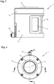
- the in the Figures 1 and 2 schematically illustrated device for cooling a shrink chuck contains one in the Figures 3 to 5 separately shown cooling attachment 1, which on a in Figure 7 schematically indicated shrink fit 2 can be placed. Such a device is used to cool a shrink chuck 2 after it has been heated for shrinking or for removing a shrunk tool.
- the cooling attachment 1 is guided vertically displaceably on a stand-shaped guide part 3.
- the guide part 3 contains a lower foot region 4 and a vertically running upper guide region 5, in which a guide rail 6 for linear guidance of the cooling attachment 1 is accommodated.
- the guide part 3 is arranged on a housing 7.
- the here L-shaped housing 7 has a front support part 8 with a horizontal support surface 9 and a rear housing part 10 with a vertical front wall surface 11.
- the guide part 3 stands with its lower foot region 4 on the vertical extending guide area 5 of the guide part 3 is fastened to the vertical front wall surface 11 of the rear housing part 10.
- the lower foot region 4 of the guide part 3 is designed in the manner of a half-shell-shaped receptacle for the positionally accurate abutment of a holder 12 for receiving the shrink fit chuck 2.
- the shrink fit chuck 2 accommodated in the holder 12 can be arranged exactly under the cooling attachment 1 are so that the cooling attachment 1 and the shrink fit are axially aligned.
- a suction line 15 for example, a flexible hose or a stable tube
- the other end of the suction line 15 is connected to a tubular suction nozzle 16, which in one Figure 2 suction unit 17 leads.
- the suction nozzle 16 is fastened next to the guide part 3 on the front wall surface 11 of the rear housing part 10.
- the suction unit 17 forms, together with the suction nozzle 16 and the suction line 15, a suction device via which a liquid coolant sprayed onto the shrink fit chuck 2 within the cooling attachment 1 can be sucked off and transported to a collecting container.
- the suction unit 17 is housed in the rear housing part 10.
- the suction unit 17 has two separate motors 18 and 19 and a collecting container 20 for collecting the cooling liquid sucked out of the cooling attachment 1.
- Further supply units and a coolant pump 21 for supplying the liquid coolant to the cooling attachment 1 can also be arranged in the rear housing part 10.
- Cooling attachment 1 shown in different views consists of an outer sleeve 22 and an inner sleeve 23 arranged within the outer sleeve 22 with the continuous interior 14.
- three recesses 25 separated by webs 24 are provided, through which the inner sleeve 23, which is preferably made of a transparent material, is visible. This allows the cooling of the shrink chuck to be monitored from the outside.
- the transparent inner sleeve 23 can also be illuminated with a colored LED (red / green) in order to indicate, for example, the inadequate or sufficient cooling by means of different colors.
- the device can also have devices for measuring the temperature of the shrink fit chuck 2 and / or for measuring the temperature of the air flow. These can be arranged on the cooling attachment 1 or on other suitable components.
- annular space 26 is provided between the outer sleeve 22 and the inner sleeve 23.
- the annular space 26 is formed by a circumferential recess 27 on the outside of the inner sleeve 23.
- the annular space 26 can also be formed in a corresponding manner by a circumferential recess on the inside of the outer sleeve 22.
- Liquid coolant can be conveyed to the annular space 26 via a coolant connection 28 on the outer sleeve 22.
- the coolant pump 21 can be connected to the coolant connection 28 via suitable lines.
- the inner sleeve 23 there are a plurality of cooling bores 29 distributed over the circumference, which lead obliquely upward from the annular space 26 to the interior 14 and open into the interior 14 through supply openings 30.
- the coolant delivered by the coolant pump 21 via a corresponding line and the coolant connection 28 to the annular space 26 can thus be sprayed via the cooling bores 29 onto the outside of a shrink fit chuck.
- the interior 14 of the inner sleeve 23 has a cross section which tapers upwards.
- a connection 31 for the suction line 15 is provided at the upper end of the inner sleeve.
- the cooling attachment 1 is placed on the shrink chuck 2 to be cooled in such a way that a sufficiently large gap remains for an air intake between an inner wall 32 of the inner ring 22 and the outside of the shrink chuck 2.
- Water or another liquid coolant is then fed to the cooling attachment 1 via the coolant connection 28. This is sprayed onto the shrink chuck 2 via the feed openings 30.
- the in Figure 2 Extraction unit 17 shown sucked air through the suction line 15 on the underside of the cooling attachment 1. The sucked-in air entrains the cooling liquid after spraying onto the shrink fit chuck 2 and transports it to the in Figure 2 shown collection container 20.
- the suction process can be carried out somewhat longer than the actual cooling, so that all the cooling liquid is sucked off and so the shrink fit chuck 2 can be removed as dry as possible after cooling.
- 14 air guiding elements can be fitted in the interior in order to bring the air flow to hidden surfaces of the shrink fit chuck.
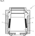
- FIG 8 A further exemplary embodiment of a cooling attachment 1 with an outer sleeve 22, an inner sleeve 23 arranged inside the outer sleeve 22 and a continuous interior 14 is shown.
- an induction device 33 is integrated in the cooling attachment 1.
- an in Figure 7 schematically shown shrink chuck 2 are heated to shrink fit a tool.
- the cooling attachment 1 can thus not only be used for cooling but also for shrinking.
- the induction device 33 has an induction coil 34 arranged in the inner sleeve 23.
Landscapes
- Physics & Mathematics (AREA)
- Electromagnetism (AREA)
- Engineering & Computer Science (AREA)
- Mechanical Engineering (AREA)
- Jigs For Machine Tools (AREA)
- Gripping On Spindles (AREA)
Applications Claiming Priority (2)
| Application Number | Priority Date | Filing Date | Title |
|---|---|---|---|
| DE102012002596A DE102012002596A1 (de) | 2012-02-13 | 2012-02-13 | Vorrichtung zur Kühlung eines Schrumpffutters |
| PCT/EP2013/052729 WO2013120821A1 (de) | 2012-02-13 | 2013-02-12 | Vorrichtung zur kühlung eines schrumpffutters |
Publications (2)
| Publication Number | Publication Date |
|---|---|
| EP2814634A1 EP2814634A1 (de) | 2014-12-24 |
| EP2814634B1 true EP2814634B1 (de) | 2020-07-15 |
Family
ID=47714095
Family Applications (1)
| Application Number | Title | Priority Date | Filing Date |
|---|---|---|---|
| EP13704095.2A Active EP2814634B1 (de) | 2012-02-13 | 2013-02-12 | Vorrichtung zur kühlung eines schrumpffutters |
Country Status (6)
| Country | Link |
|---|---|
| US (1) | US9636788B2 (enExample) |
| EP (1) | EP2814634B1 (enExample) |
| JP (1) | JP6085315B2 (enExample) |
| CN (1) | CN104136164B (enExample) |
| DE (1) | DE102012002596A1 (enExample) |
| WO (1) | WO2013120821A1 (enExample) |
Families Citing this family (5)
| Publication number | Priority date | Publication date | Assignee | Title |
|---|---|---|---|---|
| DE102017118643A1 (de) | 2017-08-16 | 2019-02-21 | Franz Haimer Maschinenbau Kg | Vorrichtung zur Kühlung eines Schrumpffutters |
| DE102017125718A1 (de) * | 2017-11-03 | 2019-05-09 | Haimer Gmbh | Schrumpffutterkühleinrichtung |
| CN111266924B (zh) * | 2020-03-30 | 2025-02-07 | 宁波利佰佳机械制造有限公司 | 一种热缩筒夹快速冷却装置 |
| DE102022114046A1 (de) | 2022-06-02 | 2023-12-07 | Haimer Gmbh | Vorrichtung zum Kühlen und/oder Trocknen eines Schrumpf-futters und Verfahren zum Kühlen und/oder Trocknen eines Werkzeughalters, insbesondere eines Schrumpffutters |
| JP2024168764A (ja) * | 2023-05-24 | 2024-12-05 | 東海理化SmartCraft株式会社 | 自動焼き嵌め装置 |
Citations (1)
| Publication number | Priority date | Publication date | Assignee | Title |
|---|---|---|---|---|
| DE102009034730A1 (de) * | 2009-07-24 | 2011-01-27 | Franz Haimer Maschinenbau Kg | Nebelkühlung |
Family Cites Families (15)
| Publication number | Priority date | Publication date | Assignee | Title |
|---|---|---|---|---|
| JPH1177443A (ja) * | 1997-09-09 | 1999-03-23 | Mst Corp | 焼きばめ装置及び該装置で使用される刃物挿入規制具 |
| EP1519632B1 (de) * | 2000-05-22 | 2009-10-07 | Haimer GmbH | Schrumpfvorrichtung für einen Werkzeughalter |
| DE10253106A1 (de) * | 2002-11-13 | 2004-06-03 | E. Zoller GmbH & Co. KG Einstell- und Messgeräte | Schrumpfvorrichtung |
| DE202004004424U1 (de) * | 2004-03-20 | 2004-07-15 | Bilz Werkzeugfabrik Gmbh & Co. Kg | Einrichtung zum thermischen Spannen und Entspannen von Werkzeugen in Schrumpffuttern |
| DE202004014564U1 (de) * | 2004-09-16 | 2004-11-18 | Marciniak, Michael | Induktionsschrumpfgerät |
| EP1924396A2 (de) | 2005-09-09 | 2008-05-28 | Franz Haimer Maschinenbau KG | Vorrichtung und verfahren zur kühlung von schrumpffuttern bzw.vorrichtung zur aufnahme von werkzeugfuttern |
| DE202006002270U1 (de) | 2006-02-14 | 2007-03-29 | Pokolm, Franz-Josef | Induktionsschrumpfvorrichtung zum Wechseln von Werkzeugen, wie Bohrer, Fräser o.dgl. |
| DE202006009799U1 (de) * | 2006-06-21 | 2007-10-25 | Lupotron Gmbh | Induktive Behandlungseinrichtung |
| DE202007000869U1 (de) * | 2006-10-06 | 2007-04-05 | E. Zoller GmbH & Co. KG Einstell- und Messgeräte | Werkzeugeinspannvorrichtung |
| WO2008098752A2 (de) * | 2007-02-16 | 2008-08-21 | Franz Haimer Maschinenbau Kg | Querfeldschrumpfvorrichtung mit mitteln zur begrenzung von magnetflussverlusten |
| DE202007007837U1 (de) * | 2007-06-01 | 2007-09-27 | Franz Haimer Maschinenbau Kg | Schrumpfspule mit direkter Werkzeugkühlung |
| DE102007044097B4 (de) * | 2007-09-14 | 2014-02-13 | Oesterle + Partner GbR (vertretungsberechtigte Gesellschafter: Hermann Oesterle, 72202 Nagold; Harald Öschger, 79312 Emmendingen) | Vorrichtung zum thermisch-induzierten Einspannen und/oder Ausspannen von Werkzeugen in eine bzw. aus einer Werkzeugaufnahme |
| US9789502B2 (en) * | 2008-06-05 | 2017-10-17 | Mary Kay Inc. | Apparatus for dispensing fluids using a removable bottle |
| DE102009017461A1 (de) | 2009-04-02 | 2010-10-07 | Helmut Diebold Gmbh & Co. Goldring-Werkzeugfabrik | Vorrichtung und Verfahren zur Kühlung eines Schrumpfspannfutters |
| DE102010033160A1 (de) * | 2010-08-03 | 2012-02-09 | Gühring Ohg | Kühlvorrichtung |
-
2012
- 2012-02-13 DE DE102012002596A patent/DE102012002596A1/de not_active Withdrawn
-
2013
- 2013-02-12 CN CN201380009255.8A patent/CN104136164B/zh active Active
- 2013-02-12 US US14/378,260 patent/US9636788B2/en active Active
- 2013-02-12 EP EP13704095.2A patent/EP2814634B1/de active Active
- 2013-02-12 WO PCT/EP2013/052729 patent/WO2013120821A1/de not_active Ceased
- 2013-02-12 JP JP2014556097A patent/JP6085315B2/ja active Active
Patent Citations (1)
| Publication number | Priority date | Publication date | Assignee | Title |
|---|---|---|---|---|
| DE102009034730A1 (de) * | 2009-07-24 | 2011-01-27 | Franz Haimer Maschinenbau Kg | Nebelkühlung |
Also Published As
| Publication number | Publication date |
|---|---|
| CN104136164A (zh) | 2014-11-05 |
| JP2015509855A (ja) | 2015-04-02 |
| JP6085315B2 (ja) | 2017-02-22 |
| EP2814634A1 (de) | 2014-12-24 |
| DE102012002596A1 (de) | 2013-08-14 |
| WO2013120821A1 (de) | 2013-08-22 |
| US9636788B2 (en) | 2017-05-02 |
| CN104136164B (zh) | 2017-11-24 |
| US20150000121A1 (en) | 2015-01-01 |
Similar Documents
| Publication | Publication Date | Title |
|---|---|---|
| EP2814634B1 (de) | Vorrichtung zur kühlung eines schrumpffutters | |
| EP2185313B1 (de) | Werkzeugmaschinenvorrichtung, werkzeugmaschine und verfahren zur herstellung einer werkzeugmaschinenvorrichtung | |
| EP2647457B1 (de) | Maschine zum Abtrennen von Abschnitten von stangen- oder rohrförmigen Werkstücken | |
| EP0194353A1 (de) | Vorrichtung zur Sicherung von Ausfallstücken an einer Elektroerosionsmaschine | |
| DE102007046695A1 (de) | Plasmaschneidvorrichtung, Plasmabrenner und Kühlvorrichtung für Plasmabrenner | |
| DE10348192B4 (de) | Integrierte Luftstromsteuerung für eine Positionierspindelbaugruppe | |
| EP0046910A1 (de) | Bearbeitungsmaschine mit einer thermischen Schneidstrahleinrichtung, insbesondere Plasmaschneidstrahleinrichtung | |
| EP3444064B1 (de) | Vorrichtung zur kühlung eines schrumpffutters | |
| DE102017127581B4 (de) | Vorrichtung und Verfahren zur Beschichtung einer Zylinderinnenfläche eines Zylinderraums eines Motorblocks | |
| DE2011697A1 (de) | Vorrichtung zum Löten und zum Trennen einer Verlötung | |
| EP1528969B1 (de) | Schrumpfvorrichtung | |
| DE2147443A1 (de) | Schmelz , Saug und Blasgerat, insbesondere fur die Reparatur von elek tronischen Schaltungen | |
| DE69706925T2 (de) | Plasmabrenner ohne Hochfrequenzzündung, mit Vorrichtungen zur Luftkühlung der Elektroden | |
| EP1584408A1 (de) | Einrichtung zum thermischen Spannen und Entspannen von Werkzeugen in Schrumpffuttern | |
| DE3834224A1 (de) | Lichtbogen-schweissbrenner zum schutzgas-lichtbogenschweissen an schwer zugaenglichen stellen | |
| DE3041621A1 (de) | Bearbeitungsmaschine mit einer thermischen schneidstrahleinrichtung | |
| DE2736686C3 (de) | Einrichtung zur elektrochemischen Bearbeitung | |
| DE3339017C2 (enExample) | ||
| DE69402599T2 (de) | Verfahren zur kontrollierten Spanabhebung bei Bohrfräser und Herstellung von Bohrfräser nach diesem Verfahren | |
| EP3479952B1 (de) | Schrumpffutterkühleinrichtung | |
| DE3317409A1 (de) | Vorrichtung zum absaugen von spaenen | |
| DE10025008B4 (de) | Vorrichtung zum thermischen Spannen und Entspannen von Werkzeugen | |
| DE102023111538B3 (de) | Trenn-Füge-Vorrichtung und Verfahren | |
| DE102012101600B4 (de) | Verfahren und Vorrichtung zum gezielten Eintrag eines Kühlmediums in eine Werkzeugaufnahme mit rotierendem Spannfutter | |
| EP1260308A1 (de) | Werkzeugmaschine mit Späne-Absaugung |
Legal Events
| Date | Code | Title | Description |
|---|---|---|---|
| PUAI | Public reference made under article 153(3) epc to a published international application that has entered the european phase |
Free format text: ORIGINAL CODE: 0009012 |
|
| 17P | Request for examination filed |
Effective date: 20140915 |
|
| AK | Designated contracting states |
Kind code of ref document: A1 Designated state(s): AL AT BE BG CH CY CZ DE DK EE ES FI FR GB GR HR HU IE IS IT LI LT LU LV MC MK MT NL NO PL PT RO RS SE SI SK SM TR |
|
| AX | Request for extension of the european patent |
Extension state: BA ME |
|
| DAX | Request for extension of the european patent (deleted) | ||
| STAA | Information on the status of an ep patent application or granted ep patent |
Free format text: STATUS: EXAMINATION IS IN PROGRESS |
|
| 17Q | First examination report despatched |
Effective date: 20180323 |
|
| GRAP | Despatch of communication of intention to grant a patent |
Free format text: ORIGINAL CODE: EPIDOSNIGR1 |
|
| STAA | Information on the status of an ep patent application or granted ep patent |
Free format text: STATUS: GRANT OF PATENT IS INTENDED |
|
| RIC1 | Information provided on ipc code assigned before grant |
Ipc: H05B 6/14 20060101ALI20200117BHEP Ipc: H05B 6/10 20060101ALI20200117BHEP Ipc: H05B 6/40 20060101ALI20200117BHEP Ipc: B23P 11/02 20060101AFI20200117BHEP |
|
| INTG | Intention to grant announced |
Effective date: 20200211 |
|
| RIN1 | Information on inventor provided before grant (corrected) |
Inventor name: HAIMER, FRANZ |
|
| GRAS | Grant fee paid |
Free format text: ORIGINAL CODE: EPIDOSNIGR3 |
|
| GRAA | (expected) grant |
Free format text: ORIGINAL CODE: 0009210 |
|
| STAA | Information on the status of an ep patent application or granted ep patent |
Free format text: STATUS: THE PATENT HAS BEEN GRANTED |
|
| AK | Designated contracting states |
Kind code of ref document: B1 Designated state(s): AL AT BE BG CH CY CZ DE DK EE ES FI FR GB GR HR HU IE IS IT LI LT LU LV MC MK MT NL NO PL PT RO RS SE SI SK SM TR |
|
| REG | Reference to a national code |
Ref country code: GB Ref legal event code: FG4D Free format text: NOT ENGLISH Ref country code: CH Ref legal event code: EP |
|
| REG | Reference to a national code |
Ref country code: DE Ref legal event code: R096 Ref document number: 502013014919 Country of ref document: DE |
|
| REG | Reference to a national code |
Ref country code: IE Ref legal event code: FG4D Free format text: LANGUAGE OF EP DOCUMENT: GERMAN |
|
| REG | Reference to a national code |
Ref country code: AT Ref legal event code: REF Ref document number: 1290457 Country of ref document: AT Kind code of ref document: T Effective date: 20200815 |
|
| REG | Reference to a national code |
Ref country code: LT Ref legal event code: MG4D |
|
| REG | Reference to a national code |
Ref country code: NL Ref legal event code: MP Effective date: 20200715 |
|
| PG25 | Lapsed in a contracting state [announced via postgrant information from national office to epo] |
Ref country code: PT Free format text: LAPSE BECAUSE OF FAILURE TO SUBMIT A TRANSLATION OF THE DESCRIPTION OR TO PAY THE FEE WITHIN THE PRESCRIBED TIME-LIMIT Effective date: 20201116 Ref country code: BG Free format text: LAPSE BECAUSE OF FAILURE TO SUBMIT A TRANSLATION OF THE DESCRIPTION OR TO PAY THE FEE WITHIN THE PRESCRIBED TIME-LIMIT Effective date: 20201015 Ref country code: LT Free format text: LAPSE BECAUSE OF FAILURE TO SUBMIT A TRANSLATION OF THE DESCRIPTION OR TO PAY THE FEE WITHIN THE PRESCRIBED TIME-LIMIT Effective date: 20200715 Ref country code: ES Free format text: LAPSE BECAUSE OF FAILURE TO SUBMIT A TRANSLATION OF THE DESCRIPTION OR TO PAY THE FEE WITHIN THE PRESCRIBED TIME-LIMIT Effective date: 20200715 Ref country code: HR Free format text: LAPSE BECAUSE OF FAILURE TO SUBMIT A TRANSLATION OF THE DESCRIPTION OR TO PAY THE FEE WITHIN THE PRESCRIBED TIME-LIMIT Effective date: 20200715 Ref country code: GR Free format text: LAPSE BECAUSE OF FAILURE TO SUBMIT A TRANSLATION OF THE DESCRIPTION OR TO PAY THE FEE WITHIN THE PRESCRIBED TIME-LIMIT Effective date: 20201016 Ref country code: NO Free format text: LAPSE BECAUSE OF FAILURE TO SUBMIT A TRANSLATION OF THE DESCRIPTION OR TO PAY THE FEE WITHIN THE PRESCRIBED TIME-LIMIT Effective date: 20201015 Ref country code: SE Free format text: LAPSE BECAUSE OF FAILURE TO SUBMIT A TRANSLATION OF THE DESCRIPTION OR TO PAY THE FEE WITHIN THE PRESCRIBED TIME-LIMIT Effective date: 20200715 Ref country code: FI Free format text: LAPSE BECAUSE OF FAILURE TO SUBMIT A TRANSLATION OF THE DESCRIPTION OR TO PAY THE FEE WITHIN THE PRESCRIBED TIME-LIMIT Effective date: 20200715 |
|
| PG25 | Lapsed in a contracting state [announced via postgrant information from national office to epo] |
Ref country code: IS Free format text: LAPSE BECAUSE OF FAILURE TO SUBMIT A TRANSLATION OF THE DESCRIPTION OR TO PAY THE FEE WITHIN THE PRESCRIBED TIME-LIMIT Effective date: 20201115 Ref country code: RS Free format text: LAPSE BECAUSE OF FAILURE TO SUBMIT A TRANSLATION OF THE DESCRIPTION OR TO PAY THE FEE WITHIN THE PRESCRIBED TIME-LIMIT Effective date: 20200715 Ref country code: LV Free format text: LAPSE BECAUSE OF FAILURE TO SUBMIT A TRANSLATION OF THE DESCRIPTION OR TO PAY THE FEE WITHIN THE PRESCRIBED TIME-LIMIT Effective date: 20200715 Ref country code: PL Free format text: LAPSE BECAUSE OF FAILURE TO SUBMIT A TRANSLATION OF THE DESCRIPTION OR TO PAY THE FEE WITHIN THE PRESCRIBED TIME-LIMIT Effective date: 20200715 |
|
| PG25 | Lapsed in a contracting state [announced via postgrant information from national office to epo] |
Ref country code: NL Free format text: LAPSE BECAUSE OF FAILURE TO SUBMIT A TRANSLATION OF THE DESCRIPTION OR TO PAY THE FEE WITHIN THE PRESCRIBED TIME-LIMIT Effective date: 20200715 |
|
| REG | Reference to a national code |
Ref country code: DE Ref legal event code: R097 Ref document number: 502013014919 Country of ref document: DE |
|
| PG25 | Lapsed in a contracting state [announced via postgrant information from national office to epo] |
Ref country code: RO Free format text: LAPSE BECAUSE OF FAILURE TO SUBMIT A TRANSLATION OF THE DESCRIPTION OR TO PAY THE FEE WITHIN THE PRESCRIBED TIME-LIMIT Effective date: 20200715 Ref country code: SM Free format text: LAPSE BECAUSE OF FAILURE TO SUBMIT A TRANSLATION OF THE DESCRIPTION OR TO PAY THE FEE WITHIN THE PRESCRIBED TIME-LIMIT Effective date: 20200715 Ref country code: CZ Free format text: LAPSE BECAUSE OF FAILURE TO SUBMIT A TRANSLATION OF THE DESCRIPTION OR TO PAY THE FEE WITHIN THE PRESCRIBED TIME-LIMIT Effective date: 20200715 Ref country code: EE Free format text: LAPSE BECAUSE OF FAILURE TO SUBMIT A TRANSLATION OF THE DESCRIPTION OR TO PAY THE FEE WITHIN THE PRESCRIBED TIME-LIMIT Effective date: 20200715 Ref country code: DK Free format text: LAPSE BECAUSE OF FAILURE TO SUBMIT A TRANSLATION OF THE DESCRIPTION OR TO PAY THE FEE WITHIN THE PRESCRIBED TIME-LIMIT Effective date: 20200715 |
|
| PLBE | No opposition filed within time limit |
Free format text: ORIGINAL CODE: 0009261 |
|
| STAA | Information on the status of an ep patent application or granted ep patent |
Free format text: STATUS: NO OPPOSITION FILED WITHIN TIME LIMIT |
|
| PG25 | Lapsed in a contracting state [announced via postgrant information from national office to epo] |
Ref country code: AL Free format text: LAPSE BECAUSE OF FAILURE TO SUBMIT A TRANSLATION OF THE DESCRIPTION OR TO PAY THE FEE WITHIN THE PRESCRIBED TIME-LIMIT Effective date: 20200715 |
|
| 26N | No opposition filed |
Effective date: 20210416 |
|
| PG25 | Lapsed in a contracting state [announced via postgrant information from national office to epo] |
Ref country code: SK Free format text: LAPSE BECAUSE OF FAILURE TO SUBMIT A TRANSLATION OF THE DESCRIPTION OR TO PAY THE FEE WITHIN THE PRESCRIBED TIME-LIMIT Effective date: 20200715 |
|
| PG25 | Lapsed in a contracting state [announced via postgrant information from national office to epo] |
Ref country code: SI Free format text: LAPSE BECAUSE OF FAILURE TO SUBMIT A TRANSLATION OF THE DESCRIPTION OR TO PAY THE FEE WITHIN THE PRESCRIBED TIME-LIMIT Effective date: 20200715 |
|
| PG25 | Lapsed in a contracting state [announced via postgrant information from national office to epo] |
Ref country code: MC Free format text: LAPSE BECAUSE OF FAILURE TO SUBMIT A TRANSLATION OF THE DESCRIPTION OR TO PAY THE FEE WITHIN THE PRESCRIBED TIME-LIMIT Effective date: 20200715 |
|
| REG | Reference to a national code |
Ref country code: BE Ref legal event code: MM Effective date: 20210228 |
|
| PG25 | Lapsed in a contracting state [announced via postgrant information from national office to epo] |
Ref country code: LU Free format text: LAPSE BECAUSE OF NON-PAYMENT OF DUE FEES Effective date: 20210212 |
|
| PG25 | Lapsed in a contracting state [announced via postgrant information from national office to epo] |
Ref country code: IE Free format text: LAPSE BECAUSE OF NON-PAYMENT OF DUE FEES Effective date: 20210212 |
|
| REG | Reference to a national code |
Ref country code: AT Ref legal event code: MM01 Ref document number: 1290457 Country of ref document: AT Kind code of ref document: T Effective date: 20210212 |
|
| PG25 | Lapsed in a contracting state [announced via postgrant information from national office to epo] |
Ref country code: AT Free format text: LAPSE BECAUSE OF NON-PAYMENT OF DUE FEES Effective date: 20210212 |
|
| PG25 | Lapsed in a contracting state [announced via postgrant information from national office to epo] |
Ref country code: BE Free format text: LAPSE BECAUSE OF NON-PAYMENT OF DUE FEES Effective date: 20210228 |
|
| PG25 | Lapsed in a contracting state [announced via postgrant information from national office to epo] |
Ref country code: HU Free format text: LAPSE BECAUSE OF FAILURE TO SUBMIT A TRANSLATION OF THE DESCRIPTION OR TO PAY THE FEE WITHIN THE PRESCRIBED TIME-LIMIT; INVALID AB INITIO Effective date: 20130212 |
|
| PG25 | Lapsed in a contracting state [announced via postgrant information from national office to epo] |
Ref country code: CY Free format text: LAPSE BECAUSE OF FAILURE TO SUBMIT A TRANSLATION OF THE DESCRIPTION OR TO PAY THE FEE WITHIN THE PRESCRIBED TIME-LIMIT Effective date: 20200715 |
|
| P01 | Opt-out of the competence of the unified patent court (upc) registered |
Effective date: 20231106 |
|
| PG25 | Lapsed in a contracting state [announced via postgrant information from national office to epo] |
Ref country code: MK Free format text: LAPSE BECAUSE OF FAILURE TO SUBMIT A TRANSLATION OF THE DESCRIPTION OR TO PAY THE FEE WITHIN THE PRESCRIBED TIME-LIMIT Effective date: 20200715 |
|
| PG25 | Lapsed in a contracting state [announced via postgrant information from national office to epo] |
Ref country code: MT Free format text: LAPSE BECAUSE OF FAILURE TO SUBMIT A TRANSLATION OF THE DESCRIPTION OR TO PAY THE FEE WITHIN THE PRESCRIBED TIME-LIMIT Effective date: 20200715 |
|
| PGFP | Annual fee paid to national office [announced via postgrant information from national office to epo] |
Ref country code: DE Payment date: 20250218 Year of fee payment: 13 |
|
| PGFP | Annual fee paid to national office [announced via postgrant information from national office to epo] |
Ref country code: CH Payment date: 20250301 Year of fee payment: 13 |
|
| PGFP | Annual fee paid to national office [announced via postgrant information from national office to epo] |
Ref country code: FR Payment date: 20250219 Year of fee payment: 13 |
|
| PGFP | Annual fee paid to national office [announced via postgrant information from national office to epo] |
Ref country code: GB Payment date: 20250220 Year of fee payment: 13 Ref country code: IT Payment date: 20250228 Year of fee payment: 13 |
|
| PGFP | Annual fee paid to national office [announced via postgrant information from national office to epo] |
Ref country code: TR Payment date: 20250204 Year of fee payment: 13 |