EP2811633B1 - Système et procédé de réduction de courant réactif sur un bus CC commun à plusieurs onduleurs - Google Patents
Système et procédé de réduction de courant réactif sur un bus CC commun à plusieurs onduleurs Download PDFInfo
- Publication number
- EP2811633B1 EP2811633B1 EP14171100.2A EP14171100A EP2811633B1 EP 2811633 B1 EP2811633 B1 EP 2811633B1 EP 14171100 A EP14171100 A EP 14171100A EP 2811633 B1 EP2811633 B1 EP 2811633B1
- Authority
- EP
- European Patent Office
- Prior art keywords
- inverter
- bus
- voltage
- phase angle
- carrier phase
- Prior art date
- Legal status (The legal status is an assumption and is not a legal conclusion. Google has not performed a legal analysis and makes no representation as to the accuracy of the status listed.)
- Active
Links
- 238000000034 method Methods 0.000 title description 5
- 230000000737 periodic effect Effects 0.000 claims description 16
- 238000004891 communication Methods 0.000 claims description 11
- 230000001172 regenerating effect Effects 0.000 claims description 10
- 230000007704 transition Effects 0.000 claims description 4
- 239000003990 capacitor Substances 0.000 description 9
- 230000001276 controlling effect Effects 0.000 description 7
- 230000008859 change Effects 0.000 description 4
- 230000000694 effects Effects 0.000 description 3
- 230000004048 modification Effects 0.000 description 3
- 238000012986 modification Methods 0.000 description 3
- 230000009467 reduction Effects 0.000 description 3
- 230000003595 spectral effect Effects 0.000 description 3
- 239000004020 conductor Substances 0.000 description 2
- 238000010586 diagram Methods 0.000 description 2
- 230000001965 increasing effect Effects 0.000 description 2
- XUIMIQQOPSSXEZ-UHFFFAOYSA-N Silicon Chemical compound [Si] XUIMIQQOPSSXEZ-UHFFFAOYSA-N 0.000 description 1
- 238000010276 construction Methods 0.000 description 1
- 230000008878 coupling Effects 0.000 description 1
- 238000010168 coupling process Methods 0.000 description 1
- 238000005859 coupling reaction Methods 0.000 description 1
- 230000001419 dependent effect Effects 0.000 description 1
- 230000001939 inductive effect Effects 0.000 description 1
- 230000007935 neutral effect Effects 0.000 description 1
- 230000008569 process Effects 0.000 description 1
- 230000001105 regulatory effect Effects 0.000 description 1
- 229910052710 silicon Inorganic materials 0.000 description 1
- 239000010703 silicon Substances 0.000 description 1
Images


Classifications
-
- H—ELECTRICITY
- H02—GENERATION; CONVERSION OR DISTRIBUTION OF ELECTRIC POWER
- H02M—APPARATUS FOR CONVERSION BETWEEN AC AND AC, BETWEEN AC AND DC, OR BETWEEN DC AND DC, AND FOR USE WITH MAINS OR SIMILAR POWER SUPPLY SYSTEMS; CONVERSION OF DC OR AC INPUT POWER INTO SURGE OUTPUT POWER; CONTROL OR REGULATION THEREOF
- H02M1/00—Details of apparatus for conversion
- H02M1/14—Arrangements for reducing ripples from dc input or output
-
- H—ELECTRICITY
- H02—GENERATION; CONVERSION OR DISTRIBUTION OF ELECTRIC POWER
- H02J—CIRCUIT ARRANGEMENTS OR SYSTEMS FOR SUPPLYING OR DISTRIBUTING ELECTRIC POWER; SYSTEMS FOR STORING ELECTRIC ENERGY
- H02J1/00—Circuit arrangements for dc mains or dc distribution networks
- H02J1/06—Two-wire systems
-
- H—ELECTRICITY
- H02—GENERATION; CONVERSION OR DISTRIBUTION OF ELECTRIC POWER
- H02M—APPARATUS FOR CONVERSION BETWEEN AC AND AC, BETWEEN AC AND DC, OR BETWEEN DC AND DC, AND FOR USE WITH MAINS OR SIMILAR POWER SUPPLY SYSTEMS; CONVERSION OF DC OR AC INPUT POWER INTO SURGE OUTPUT POWER; CONTROL OR REGULATION THEREOF
- H02M7/00—Conversion of ac power input into dc power output; Conversion of dc power input into ac power output
- H02M7/42—Conversion of dc power input into ac power output without possibility of reversal
- H02M7/44—Conversion of dc power input into ac power output without possibility of reversal by static converters
- H02M7/48—Conversion of dc power input into ac power output without possibility of reversal by static converters using discharge tubes with control electrode or semiconductor devices with control electrode
- H02M7/493—Conversion of dc power input into ac power output without possibility of reversal by static converters using discharge tubes with control electrode or semiconductor devices with control electrode the static converters being arranged for operation in parallel
-
- H—ELECTRICITY
- H02—GENERATION; CONVERSION OR DISTRIBUTION OF ELECTRIC POWER
- H02M—APPARATUS FOR CONVERSION BETWEEN AC AND AC, BETWEEN AC AND DC, OR BETWEEN DC AND DC, AND FOR USE WITH MAINS OR SIMILAR POWER SUPPLY SYSTEMS; CONVERSION OF DC OR AC INPUT POWER INTO SURGE OUTPUT POWER; CONTROL OR REGULATION THEREOF
- H02M1/00—Details of apparatus for conversion
- H02M1/0043—Converters switched with a phase shift, i.e. interleaved
-
- H—ELECTRICITY
- H02—GENERATION; CONVERSION OR DISTRIBUTION OF ELECTRIC POWER
- H02M—APPARATUS FOR CONVERSION BETWEEN AC AND AC, BETWEEN AC AND DC, OR BETWEEN DC AND DC, AND FOR USE WITH MAINS OR SIMILAR POWER SUPPLY SYSTEMS; CONVERSION OF DC OR AC INPUT POWER INTO SURGE OUTPUT POWER; CONTROL OR REGULATION THEREOF
- H02M1/00—Details of apparatus for conversion
- H02M1/0067—Converter structures employing plural converter units, other than for parallel operation of the units on a single load
- H02M1/008—Plural converter units for generating at two or more independent and non-parallel outputs, e.g. systems with plural point of load switching regulators
Landscapes
- Engineering & Computer Science (AREA)
- Power Engineering (AREA)
- Inverter Devices (AREA)
Claims (8)
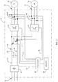
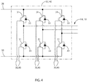
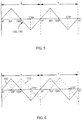
- Système configuré pour réduire un courant réactif présent sur un bus (24) de courant continu, DC, soit Direct Current, le bus DC ayant un premier rail de tension et un deuxième rail de tension dans lequel le bus DC est configuré pour avoir un potentiel de tension DC présent entre le premier rail de tension et le deuxième rail de tension, le système comprenant :une pluralité d'onduleurs (15), le courant réactif comportant des courants ondulés provenant de la pluralité de commutations d'onduleurs, chaque onduleur comportant :une entrée configurée pour se connecter aux premier et deuxième rails de tension du bus DC,une sortie configurée pour se connecter à une charge de courant alternatif, AC, soit Alternating Current, où la charge AC est un moteur,une pluralité de dispositifs de commutation, chaque dispositif de commutation étant commandé par un signal de commutation pour connecter et déconnecter en alternance l'entrée à/de la sortie, etun module de modulation configuré pour déterminer, à un intervalle périodique, chacun des signaux de commutation, où, pendant chaque intervalle périodique, le module de modulation détermine chacun des signaux de commutation en fonction d'un signal de porteuse qui répète chaque intervalle périodique et d'au moins un signal de référence de tension, où chaque signal de porteuse est défini, au moins en partie, par un angle de phase de porteuse et chaque signal de référence de tension correspond à une tension de sortie souhaitée pour chaque phase de la charge AC ;un signal de synchronisation en communication avec chacun des modules de modulation, où le signal de synchronisation est utilisé par chaque module de modulation pour démarrer son intervalle périodique correspondant en même temps ;un dispositif de commande configuré pour générer un angle de phase de porteuse pour chaque onduleur,dans lequel l'angle de phase de porteuse pour chaque onduleur est mis à jour dynamiquement pendant le fonctionnement du moteur correspondant et dépend du fonctionnement du moteur correspondant en mode entraînement ou en mode régénération,dans lequel le signal de porteuse est une première forme d'onde pendant chacun des modes entraînement et régénération, et le signal de porteuse est une deuxième forme d'onde, différente de la première forme d'onde, pendant au moins un intervalle périodique (210) pour faire la transition entre les modes entraînement et régénération ; etun support de communication (17) qui s'étend entre le dispositif de commande et chaque onduleur pour transmettre l'angle de phase de porteuse entre le dispositif de commande et chaque onduleur de sorte qu'un premier courant réactif généré par la pluralité de dispositifs de commutation connectant et déconnectant en alternance l'entrée à/de la sortie dans un premier onduleur (32) soit au moins partiellement annulé par un deuxième courant réactif généré par la pluralité de dispositifs de commutation connectant et déconnectant en alternance l'entrée à/de la sortie dans un deuxième onduleur (42).
- Système de la revendication 1, dans lequel le dispositif de commande comporte un processeur (21) configuré pour générer chacun des angles de phase de porteuse.
- Système de la revendication 1 ou 2, dans lequel le processeur (21) est en outre configuré pour générer chacun des angles de phase de porteuse pour minimiser le courant réactif présent sur le bus DC (24).
- Système de l'une quelconque des revendications 1 à 3, dans lequel le processeur (21) est en outre configuré pour générer chacun des angles de phase de porteuse pour minimiser les émissions par conduction générées par chacun de la pluralité d'onduleurs.
- Système de l'une quelconque des revendications 1 à 4, dans lequel chaque onduleur (15) comporte en outre un processeur (38, 48) et le dispositif de commande est défini, au moins en partie, par les processeurs de chaque onduleur et dans lequel chacun des processeurs est configuré pour générer l'angle de phase de porteuse pour son onduleur correspondant.
- Système de l'une quelconque des revendications 1 à 5, dans lequel l'angle de phase de porteuse est déterminé en fonction d'un nombre total de la pluralité d'onduleurs (15) connectés au bus DC (24).
- Système de l'une quelconque des revendications 1 à 6, dans lequel la charge AC connectée à chaque onduleur (15) est un moteur AC et dans lequel l'angle de phase de porteuse de chacun des onduleurs est déterminé en fonction du fonctionnement du moteur AC en mode entraînement ou en mode régénération.
- Système de l'une quelconque des revendications 1 à 7, dans lequel chaque onduleur (15) comporte un capteur de courant configuré pour générer un signal correspondant au courant présent à l'entrée et dans lequel le dispositif de commande est configuré pour générer l'angle de phase de porteuse pour chaque onduleur en fonction du signal provenant du capteur de courant.
Applications Claiming Priority (1)
| Application Number | Priority Date | Filing Date | Title |
|---|---|---|---|
| US13/910,656 US9515484B2 (en) | 2013-06-05 | 2013-06-05 | System and method for reducing reactive current on a common DC bus with multiple inverters |
Publications (3)
| Publication Number | Publication Date |
|---|---|
| EP2811633A2 EP2811633A2 (fr) | 2014-12-10 |
| EP2811633A3 EP2811633A3 (fr) | 2015-07-15 |
| EP2811633B1 true EP2811633B1 (fr) | 2021-04-14 |
Family
ID=50842188
Family Applications (1)
| Application Number | Title | Priority Date | Filing Date |
|---|---|---|---|
| EP14171100.2A Active EP2811633B1 (fr) | 2013-06-05 | 2014-06-04 | Système et procédé de réduction de courant réactif sur un bus CC commun à plusieurs onduleurs |
Country Status (3)
| Country | Link |
|---|---|
| US (1) | US9515484B2 (fr) |
| EP (1) | EP2811633B1 (fr) |
| CN (1) | CN104242739A (fr) |
Families Citing this family (22)
| Publication number | Priority date | Publication date | Assignee | Title |
|---|---|---|---|---|
| DE102013225603B4 (de) * | 2013-12-11 | 2015-07-16 | Siemens Aktiengesellschaft | Stromrichtervorrichtung für eine Ein- oder Mehrachsanordnung und Betriebsverfahren |
| JP6424486B2 (ja) * | 2014-06-18 | 2018-11-21 | 富士電機株式会社 | 電力変換装置の多重化システム |
| US9882421B2 (en) * | 2015-05-14 | 2018-01-30 | Rockwell Automation Technologies, Inc. | Method and apparatus for increasing current capacity of a distributed drive system |
| EP3213952B1 (fr) * | 2016-03-02 | 2020-08-26 | Airbus Defence and Space GmbH | Systeme d'entrainement electrique pour un aeronef et procede de fonctionnement |
| DE102017006887A1 (de) * | 2016-09-22 | 2018-03-22 | Sew-Eurodrive Gmbh & Co Kg | System, umfassend einen ersten Wechselrichter und einen zweiten Wechselrichter, und ein Verfahren zum Betreiben des Systems |
| US10291147B2 (en) * | 2016-09-29 | 2019-05-14 | Ge Global Sourcing Llc | Current reduction system for inverters connected to a common bus |
| EP3324527B1 (fr) | 2016-11-18 | 2021-06-30 | Aros Electronics AB | Élimination d'ondulation de bus cc pour machines électriques polyphasées |
| DE102016223349A1 (de) | 2016-11-24 | 2018-05-24 | Brose Fahrzeugteile GmbH & Co. Kommanditgesellschaft, Würzburg | Verfahren zum Betrieb eines bürstenlosen Elektromotors eines Kraftfahrzeugs |
| DE102016124099A1 (de) * | 2016-12-12 | 2018-06-14 | Ebm-Papst Mulfingen Gmbh & Co. Kg | EMV-Kühlgerät |
| US10291145B2 (en) | 2016-12-14 | 2019-05-14 | Caterpillar Inc. | Inverter assembly for electric power system |
| US10581361B2 (en) * | 2017-01-17 | 2020-03-03 | Ford Global Technologies, Llc | Multiple inverter system for an electric machine |
| JP6383028B2 (ja) * | 2017-02-10 | 2018-08-29 | ファナック株式会社 | モータ駆動装置 |
| DE102017009836A1 (de) * | 2017-03-14 | 2018-09-20 | Diehl Ako Stiftung & Co. Kg | Verfahren zum Betrieb eines ersten Umrichters und eines zweiten Umrichters |
| AU2018253038B2 (en) * | 2017-04-12 | 2020-09-03 | Ge Global Sourcing Llc | Current reduction system for inverters connected to a common bus |
| EP3425786A1 (fr) * | 2017-07-03 | 2019-01-09 | Hamilton Sundstrand Corporation | Système d'entraînement de moteur |
| JP7007577B2 (ja) * | 2018-02-26 | 2022-01-24 | ダイキン工業株式会社 | Ac-ac変換装置、電力変換装置 |
| CN111082710A (zh) * | 2019-12-25 | 2020-04-28 | 深圳万讯自控股份有限公司 | 一种伺服电机直流母线载波控制拓扑结构及方法 |
| US11664743B2 (en) | 2020-08-14 | 2023-05-30 | Ut-Battelle, Llc | System and method of inverter control |
| DE102020124496A1 (de) * | 2020-09-21 | 2022-03-24 | Audi Aktiengesellschaft | Verfahren zum Betreiben von wenigstens zwei mit einem Gleichstromnetzwerk verbundenen Wechselrichtern und Kraftfahrzeug |
| EP4047809A1 (fr) | 2021-02-22 | 2022-08-24 | Hamilton Sundstrand Corporation | Architecture de distribution de commande |
| US11539283B1 (en) * | 2021-06-04 | 2022-12-27 | Rockwell Automation Technologies, Inc. | System and method for reducing delay in the modulation of a multi-phase output voltage from an inverter |
| DE102022206581A1 (de) | 2022-06-29 | 2024-01-04 | Zf Friedrichshafen Ag | Verfahren zur Steuerung des Betriebs einer elektrischen Anordnung |
Family Cites Families (15)
| Publication number | Priority date | Publication date | Assignee | Title |
|---|---|---|---|---|
| US4628460A (en) * | 1982-09-17 | 1986-12-09 | Eaton Corporation | Microprocessor controlled phase shifter |
| US5408404A (en) | 1993-03-25 | 1995-04-18 | Rockwell International Corp. | High frequency interleaved DC-to-AC power converter apparatus |
| JP3555567B2 (ja) | 2000-09-04 | 2004-08-18 | 日産自動車株式会社 | 回転電機の制御装置 |
| US6864646B2 (en) | 2003-02-14 | 2005-03-08 | General Motors Corporation | Multiple inverter system with low power bus ripples and method therefor |
| JP2004274842A (ja) * | 2003-03-06 | 2004-09-30 | Suzuki Motor Corp | 交流発電機の発電制御装置 |
| US6897698B1 (en) | 2003-05-30 | 2005-05-24 | O2Micro International Limited | Phase shifting and PWM driving circuits and methods |
| US7425806B2 (en) * | 2004-04-12 | 2008-09-16 | York International Corporation | System and method for controlling a variable speed drive |
| US7295448B2 (en) | 2004-06-04 | 2007-11-13 | Siemens Vdo Automotive Corporation | Interleaved power converter |
| TWI265675B (en) | 2004-10-22 | 2006-11-01 | Chung Shan Inst Of Science | Interleaving control type inverter |
| JP2006149141A (ja) * | 2004-11-24 | 2006-06-08 | Nippon Densan Corp | モータ駆動制御方法及びモータ駆動制御装置 |
| US8421393B2 (en) * | 2007-10-19 | 2013-04-16 | Lockheed Martin Corporation | System and method for pulse edge synchronization |
| DE102008037543A1 (de) * | 2007-12-28 | 2009-07-02 | DENSO CORPORARTION, Kariya-shi | Motorsteuervorrichtung, Fahrzeuglüfter-Ansteuervorrichtung und Motorsteuerverfahren |
| CN101860319B (zh) * | 2010-06-01 | 2012-05-23 | 华东交通大学 | 一种多目标的大功率逆变器共模电压抑制方法 |
| US8963453B2 (en) * | 2010-12-16 | 2015-02-24 | Rockwell Automation Technologies, Inc. | Method and apparatus for synchronization of pulse width modulation |
| FR2979493B1 (fr) | 2011-08-25 | 2013-09-13 | Converteam Technology Ltd | Compensateur d'energie reactive comprenant n onduleurs en parallele, n bancs de condensateur(s) et des moyens de connexion des bancs au travers de composants electriques passifs |
-
2013
- 2013-06-05 US US13/910,656 patent/US9515484B2/en active Active
-
2014
- 2014-06-04 EP EP14171100.2A patent/EP2811633B1/fr active Active
- 2014-06-05 CN CN201410246629.4A patent/CN104242739A/zh active Pending
Non-Patent Citations (1)
| Title |
|---|
| None * |
Also Published As
| Publication number | Publication date |
|---|---|
| US9515484B2 (en) | 2016-12-06 |
| EP2811633A3 (fr) | 2015-07-15 |
| US20140361613A1 (en) | 2014-12-11 |
| EP2811633A2 (fr) | 2014-12-10 |
| CN104242739A (zh) | 2014-12-24 |
Similar Documents
| Publication | Publication Date | Title |
|---|---|---|
| EP2811633B1 (fr) | Système et procédé de réduction de courant réactif sur un bus CC commun à plusieurs onduleurs | |
| JP4433099B1 (ja) | 電力変換装置 | |
| RU2381610C1 (ru) | Регулятор мощности и транспортное средство, оснащенное регулятором мощности | |
| US8963453B2 (en) | Method and apparatus for synchronization of pulse width modulation | |
| CN107482980B (zh) | 一种抑制共模噪声的三相交流电机驱动系统 | |
| KR101588147B1 (ko) | 전력 변환 장치 | |
| JP5377604B2 (ja) | 電力変換装置 | |
| WO2014136142A1 (fr) | Système pour commander un moteur à courant alternatif | |
| CN111262235B (zh) | 用于运行与直流电网连接的至少两个脉冲变换器的方法、电路组件和机动车 | |
| KR101579390B1 (ko) | 전력 변환 장치 | |
| EP2605395A1 (fr) | Inverseur de véhicule relié à des rails | |
| JP2017192196A (ja) | 交流電動機の制御装置 | |
| US11218107B2 (en) | Control device for power converter | |
| JP2013055868A5 (fr) | ||
| JP2013055866A5 (fr) | ||
| JP2013055864A5 (fr) | ||
| CN111837327A (zh) | 电力转换装置、电动机驱动系统及控制方法 | |
| CN104471849A (zh) | 用于飞机电力系统谐波抑制的有源功率因数校正 | |
| JP2010220382A (ja) | 電力変換装置 | |
| JP6091405B2 (ja) | エレベーターかご給電装置 | |
| US10122253B2 (en) | Power conversion apparatus and initial charging method of the same | |
| WO2015193964A1 (fr) | Dispositif de commande de véhicule électrique | |
| JPH10295080A (ja) | サイリスタ変換装置 | |
| KR101592454B1 (ko) | 전지 전력 저장 시스템의 순환전류 저감형 droop 제어 시스템 | |
| Kumar et al. | A Zig-Zag Transformer and Three-leg VSC Based DSTATCOM for a Diesel Generator Based Microgrid |
Legal Events
| Date | Code | Title | Description |
|---|---|---|---|
| PUAI | Public reference made under article 153(3) epc to a published international application that has entered the european phase |
Free format text: ORIGINAL CODE: 0009012 |
|
| 17P | Request for examination filed |
Effective date: 20140604 |
|
| AK | Designated contracting states |
Kind code of ref document: A2 Designated state(s): AL AT BE BG CH CY CZ DE DK EE ES FI FR GB GR HR HU IE IS IT LI LT LU LV MC MK MT NL NO PL PT RO RS SE SI SK SM TR |
|
| AX | Request for extension of the european patent |
Extension state: BA ME |
|
| RIN1 | Information on inventor provided before grant (corrected) |
Inventor name: HUANG, RONGJUN Inventor name: WINTERHALTER, CRAIG Inventor name: GRIES, MARK Inventor name: LI, YE |
|
| PUAL | Search report despatched |
Free format text: ORIGINAL CODE: 0009013 |
|
| AK | Designated contracting states |
Kind code of ref document: A3 Designated state(s): AL AT BE BG CH CY CZ DE DK EE ES FI FR GB GR HR HU IE IS IT LI LT LU LV MC MK MT NL NO PL PT RO RS SE SI SK SM TR |
|
| AX | Request for extension of the european patent |
Extension state: BA ME |
|
| RIC1 | Information provided on ipc code assigned before grant |
Ipc: H02M 1/00 20070101ALI20150610BHEP Ipc: H02M 7/493 20070101ALI20150610BHEP Ipc: H02M 1/14 20060101AFI20150610BHEP |
|
| R17P | Request for examination filed (corrected) |
Effective date: 20160115 |
|
| RBV | Designated contracting states (corrected) |
Designated state(s): AL AT BE BG CH CY CZ DE DK EE ES FI FR GB GR HR HU IE IS IT LI LT LU LV MC MK MT NL NO PL PT RO RS SE SI SK SM TR |
|
| STAA | Information on the status of an ep patent application or granted ep patent |
Free format text: STATUS: EXAMINATION IS IN PROGRESS |
|
| 17Q | First examination report despatched |
Effective date: 20170215 |
|
| GRAP | Despatch of communication of intention to grant a patent |
Free format text: ORIGINAL CODE: EPIDOSNIGR1 |
|
| STAA | Information on the status of an ep patent application or granted ep patent |
Free format text: STATUS: GRANT OF PATENT IS INTENDED |
|
| INTG | Intention to grant announced |
Effective date: 20200806 |
|
| GRAJ | Information related to disapproval of communication of intention to grant by the applicant or resumption of examination proceedings by the epo deleted |
Free format text: ORIGINAL CODE: EPIDOSDIGR1 |
|
| STAA | Information on the status of an ep patent application or granted ep patent |
Free format text: STATUS: EXAMINATION IS IN PROGRESS |
|
| GRAP | Despatch of communication of intention to grant a patent |
Free format text: ORIGINAL CODE: EPIDOSNIGR1 |
|
| STAA | Information on the status of an ep patent application or granted ep patent |
Free format text: STATUS: GRANT OF PATENT IS INTENDED |
|
| INTC | Intention to grant announced (deleted) | ||
| INTG | Intention to grant announced |
Effective date: 20201125 |
|
| GRAS | Grant fee paid |
Free format text: ORIGINAL CODE: EPIDOSNIGR3 |
|
| GRAA | (expected) grant |
Free format text: ORIGINAL CODE: 0009210 |
|
| STAA | Information on the status of an ep patent application or granted ep patent |
Free format text: STATUS: THE PATENT HAS BEEN GRANTED |
|
| AK | Designated contracting states |
Kind code of ref document: B1 Designated state(s): AL AT BE BG CH CY CZ DE DK EE ES FI FR GB GR HR HU IE IS IT LI LT LU LV MC MK MT NL NO PL PT RO RS SE SI SK SM TR |
|
| REG | Reference to a national code |
Ref country code: GB Ref legal event code: FG4D |
|
| REG | Reference to a national code |
Ref country code: CH Ref legal event code: EP |
|
| REG | Reference to a national code |
Ref country code: DE Ref legal event code: R096 Ref document number: 602014076529 Country of ref document: DE |
|
| REG | Reference to a national code |
Ref country code: IE Ref legal event code: FG4D |
|
| REG | Reference to a national code |
Ref country code: AT Ref legal event code: REF Ref document number: 1383354 Country of ref document: AT Kind code of ref document: T Effective date: 20210515 |
|
| REG | Reference to a national code |
Ref country code: LT Ref legal event code: MG9D |
|
| REG | Reference to a national code |
Ref country code: AT Ref legal event code: MK05 Ref document number: 1383354 Country of ref document: AT Kind code of ref document: T Effective date: 20210414 |
|
| REG | Reference to a national code |
Ref country code: NL Ref legal event code: MP Effective date: 20210414 |
|
| PG25 | Lapsed in a contracting state [announced via postgrant information from national office to epo] |
Ref country code: NL Free format text: LAPSE BECAUSE OF FAILURE TO SUBMIT A TRANSLATION OF THE DESCRIPTION OR TO PAY THE FEE WITHIN THE PRESCRIBED TIME-LIMIT Effective date: 20210414 Ref country code: LT Free format text: LAPSE BECAUSE OF FAILURE TO SUBMIT A TRANSLATION OF THE DESCRIPTION OR TO PAY THE FEE WITHIN THE PRESCRIBED TIME-LIMIT Effective date: 20210414 Ref country code: FI Free format text: LAPSE BECAUSE OF FAILURE TO SUBMIT A TRANSLATION OF THE DESCRIPTION OR TO PAY THE FEE WITHIN THE PRESCRIBED TIME-LIMIT Effective date: 20210414 Ref country code: AT Free format text: LAPSE BECAUSE OF FAILURE TO SUBMIT A TRANSLATION OF THE DESCRIPTION OR TO PAY THE FEE WITHIN THE PRESCRIBED TIME-LIMIT Effective date: 20210414 Ref country code: BG Free format text: LAPSE BECAUSE OF FAILURE TO SUBMIT A TRANSLATION OF THE DESCRIPTION OR TO PAY THE FEE WITHIN THE PRESCRIBED TIME-LIMIT Effective date: 20210714 Ref country code: HR Free format text: LAPSE BECAUSE OF FAILURE TO SUBMIT A TRANSLATION OF THE DESCRIPTION OR TO PAY THE FEE WITHIN THE PRESCRIBED TIME-LIMIT Effective date: 20210414 |
|
| PG25 | Lapsed in a contracting state [announced via postgrant information from national office to epo] |
Ref country code: GR Free format text: LAPSE BECAUSE OF FAILURE TO SUBMIT A TRANSLATION OF THE DESCRIPTION OR TO PAY THE FEE WITHIN THE PRESCRIBED TIME-LIMIT Effective date: 20210715 Ref country code: LV Free format text: LAPSE BECAUSE OF FAILURE TO SUBMIT A TRANSLATION OF THE DESCRIPTION OR TO PAY THE FEE WITHIN THE PRESCRIBED TIME-LIMIT Effective date: 20210414 Ref country code: IS Free format text: LAPSE BECAUSE OF FAILURE TO SUBMIT A TRANSLATION OF THE DESCRIPTION OR TO PAY THE FEE WITHIN THE PRESCRIBED TIME-LIMIT Effective date: 20210814 Ref country code: PT Free format text: LAPSE BECAUSE OF FAILURE TO SUBMIT A TRANSLATION OF THE DESCRIPTION OR TO PAY THE FEE WITHIN THE PRESCRIBED TIME-LIMIT Effective date: 20210816 Ref country code: NO Free format text: LAPSE BECAUSE OF FAILURE TO SUBMIT A TRANSLATION OF THE DESCRIPTION OR TO PAY THE FEE WITHIN THE PRESCRIBED TIME-LIMIT Effective date: 20210714 Ref country code: PL Free format text: LAPSE BECAUSE OF FAILURE TO SUBMIT A TRANSLATION OF THE DESCRIPTION OR TO PAY THE FEE WITHIN THE PRESCRIBED TIME-LIMIT Effective date: 20210414 Ref country code: ES Free format text: LAPSE BECAUSE OF FAILURE TO SUBMIT A TRANSLATION OF THE DESCRIPTION OR TO PAY THE FEE WITHIN THE PRESCRIBED TIME-LIMIT Effective date: 20210414 Ref country code: SE Free format text: LAPSE BECAUSE OF FAILURE TO SUBMIT A TRANSLATION OF THE DESCRIPTION OR TO PAY THE FEE WITHIN THE PRESCRIBED TIME-LIMIT Effective date: 20210414 Ref country code: RS Free format text: LAPSE BECAUSE OF FAILURE TO SUBMIT A TRANSLATION OF THE DESCRIPTION OR TO PAY THE FEE WITHIN THE PRESCRIBED TIME-LIMIT Effective date: 20210414 |
|
| REG | Reference to a national code |
Ref country code: DE Ref legal event code: R097 Ref document number: 602014076529 Country of ref document: DE |
|
| PG25 | Lapsed in a contracting state [announced via postgrant information from national office to epo] |
Ref country code: SM Free format text: LAPSE BECAUSE OF FAILURE TO SUBMIT A TRANSLATION OF THE DESCRIPTION OR TO PAY THE FEE WITHIN THE PRESCRIBED TIME-LIMIT Effective date: 20210414 Ref country code: SK Free format text: LAPSE BECAUSE OF FAILURE TO SUBMIT A TRANSLATION OF THE DESCRIPTION OR TO PAY THE FEE WITHIN THE PRESCRIBED TIME-LIMIT Effective date: 20210414 Ref country code: EE Free format text: LAPSE BECAUSE OF FAILURE TO SUBMIT A TRANSLATION OF THE DESCRIPTION OR TO PAY THE FEE WITHIN THE PRESCRIBED TIME-LIMIT Effective date: 20210414 Ref country code: CZ Free format text: LAPSE BECAUSE OF FAILURE TO SUBMIT A TRANSLATION OF THE DESCRIPTION OR TO PAY THE FEE WITHIN THE PRESCRIBED TIME-LIMIT Effective date: 20210414 Ref country code: DK Free format text: LAPSE BECAUSE OF FAILURE TO SUBMIT A TRANSLATION OF THE DESCRIPTION OR TO PAY THE FEE WITHIN THE PRESCRIBED TIME-LIMIT Effective date: 20210414 Ref country code: RO Free format text: LAPSE BECAUSE OF FAILURE TO SUBMIT A TRANSLATION OF THE DESCRIPTION OR TO PAY THE FEE WITHIN THE PRESCRIBED TIME-LIMIT Effective date: 20210414 Ref country code: MC Free format text: LAPSE BECAUSE OF FAILURE TO SUBMIT A TRANSLATION OF THE DESCRIPTION OR TO PAY THE FEE WITHIN THE PRESCRIBED TIME-LIMIT Effective date: 20210414 |
|
| REG | Reference to a national code |
Ref country code: CH Ref legal event code: PL |
|
| PLBE | No opposition filed within time limit |
Free format text: ORIGINAL CODE: 0009261 |
|
| STAA | Information on the status of an ep patent application or granted ep patent |
Free format text: STATUS: NO OPPOSITION FILED WITHIN TIME LIMIT |
|
| REG | Reference to a national code |
Ref country code: BE Ref legal event code: MM Effective date: 20210630 |
|
| 26N | No opposition filed |
Effective date: 20220117 |
|
| PG25 | Lapsed in a contracting state [announced via postgrant information from national office to epo] |
Ref country code: LU Free format text: LAPSE BECAUSE OF NON-PAYMENT OF DUE FEES Effective date: 20210604 |
|
| PG25 | Lapsed in a contracting state [announced via postgrant information from national office to epo] |
Ref country code: LI Free format text: LAPSE BECAUSE OF NON-PAYMENT OF DUE FEES Effective date: 20210630 Ref country code: IE Free format text: LAPSE BECAUSE OF NON-PAYMENT OF DUE FEES Effective date: 20210604 Ref country code: CH Free format text: LAPSE BECAUSE OF NON-PAYMENT OF DUE FEES Effective date: 20210630 |
|
| PG25 | Lapsed in a contracting state [announced via postgrant information from national office to epo] |
Ref country code: IS Free format text: LAPSE BECAUSE OF FAILURE TO SUBMIT A TRANSLATION OF THE DESCRIPTION OR TO PAY THE FEE WITHIN THE PRESCRIBED TIME-LIMIT Effective date: 20210814 Ref country code: AL Free format text: LAPSE BECAUSE OF FAILURE TO SUBMIT A TRANSLATION OF THE DESCRIPTION OR TO PAY THE FEE WITHIN THE PRESCRIBED TIME-LIMIT Effective date: 20210414 |
|
| PG25 | Lapsed in a contracting state [announced via postgrant information from national office to epo] |
Ref country code: IT Free format text: LAPSE BECAUSE OF FAILURE TO SUBMIT A TRANSLATION OF THE DESCRIPTION OR TO PAY THE FEE WITHIN THE PRESCRIBED TIME-LIMIT Effective date: 20210414 Ref country code: BE Free format text: LAPSE BECAUSE OF NON-PAYMENT OF DUE FEES Effective date: 20210630 |
|
| PG25 | Lapsed in a contracting state [announced via postgrant information from national office to epo] |
Ref country code: HU Free format text: LAPSE BECAUSE OF FAILURE TO SUBMIT A TRANSLATION OF THE DESCRIPTION OR TO PAY THE FEE WITHIN THE PRESCRIBED TIME-LIMIT; INVALID AB INITIO Effective date: 20140604 |
|
| P01 | Opt-out of the competence of the unified patent court (upc) registered |
Effective date: 20230404 |
|
| PG25 | Lapsed in a contracting state [announced via postgrant information from national office to epo] |
Ref country code: CY Free format text: LAPSE BECAUSE OF FAILURE TO SUBMIT A TRANSLATION OF THE DESCRIPTION OR TO PAY THE FEE WITHIN THE PRESCRIBED TIME-LIMIT Effective date: 20210414 |
|
| PGFP | Annual fee paid to national office [announced via postgrant information from national office to epo] |
Ref country code: FR Payment date: 20230523 Year of fee payment: 10 Ref country code: DE Payment date: 20230523 Year of fee payment: 10 |
|
| PGFP | Annual fee paid to national office [announced via postgrant information from national office to epo] |
Ref country code: GB Payment date: 20230523 Year of fee payment: 10 |
|
| PG25 | Lapsed in a contracting state [announced via postgrant information from national office to epo] |
Ref country code: MK Free format text: LAPSE BECAUSE OF FAILURE TO SUBMIT A TRANSLATION OF THE DESCRIPTION OR TO PAY THE FEE WITHIN THE PRESCRIBED TIME-LIMIT Effective date: 20210414 |