EP2811548A1 - Batteriemodul mit Trennanordnung - Google Patents
Batteriemodul mit Trennanordnung Download PDFInfo
- Publication number
- EP2811548A1 EP2811548A1 EP20130171050 EP13171050A EP2811548A1 EP 2811548 A1 EP2811548 A1 EP 2811548A1 EP 20130171050 EP20130171050 EP 20130171050 EP 13171050 A EP13171050 A EP 13171050A EP 2811548 A1 EP2811548 A1 EP 2811548A1
- Authority
- EP
- European Patent Office
- Prior art keywords
- battery module
- battery
- switch
- bypass
- disconnect
- Prior art date
- Legal status (The legal status is an assumption and is not a legal conclusion. Google has not performed a legal analysis and makes no representation as to the accuracy of the status listed.)
- Granted
Links
Images


Classifications
-
- B—PERFORMING OPERATIONS; TRANSPORTING
- B60—VEHICLES IN GENERAL
- B60L—PROPULSION OF ELECTRICALLY-PROPELLED VEHICLES; SUPPLYING ELECTRIC POWER FOR AUXILIARY EQUIPMENT OF ELECTRICALLY-PROPELLED VEHICLES; ELECTRODYNAMIC BRAKE SYSTEMS FOR VEHICLES IN GENERAL; MAGNETIC SUSPENSION OR LEVITATION FOR VEHICLES; MONITORING OPERATING VARIABLES OF ELECTRICALLY-PROPELLED VEHICLES; ELECTRIC SAFETY DEVICES FOR ELECTRICALLY-PROPELLED VEHICLES
- B60L58/00—Methods or circuit arrangements for monitoring or controlling batteries or fuel cells, specially adapted for electric vehicles
- B60L58/10—Methods or circuit arrangements for monitoring or controlling batteries or fuel cells, specially adapted for electric vehicles for monitoring or controlling batteries
- B60L58/18—Methods or circuit arrangements for monitoring or controlling batteries or fuel cells, specially adapted for electric vehicles for monitoring or controlling batteries of two or more battery modules
- B60L58/22—Balancing the charge of battery modules
-
- B—PERFORMING OPERATIONS; TRANSPORTING
- B60—VEHICLES IN GENERAL
- B60L—PROPULSION OF ELECTRICALLY-PROPELLED VEHICLES; SUPPLYING ELECTRIC POWER FOR AUXILIARY EQUIPMENT OF ELECTRICALLY-PROPELLED VEHICLES; ELECTRODYNAMIC BRAKE SYSTEMS FOR VEHICLES IN GENERAL; MAGNETIC SUSPENSION OR LEVITATION FOR VEHICLES; MONITORING OPERATING VARIABLES OF ELECTRICALLY-PROPELLED VEHICLES; ELECTRIC SAFETY DEVICES FOR ELECTRICALLY-PROPELLED VEHICLES
- B60L3/00—Electric devices on electrically-propelled vehicles for safety purposes; Monitoring operating variables, e.g. speed, deceleration or energy consumption
- B60L3/0023—Detecting, eliminating, remedying or compensating for drive train abnormalities, e.g. failures within the drive train
- B60L3/0046—Detecting, eliminating, remedying or compensating for drive train abnormalities, e.g. failures within the drive train relating to electric energy storage systems, e.g. batteries or capacitors
-
- B—PERFORMING OPERATIONS; TRANSPORTING
- B60—VEHICLES IN GENERAL
- B60L—PROPULSION OF ELECTRICALLY-PROPELLED VEHICLES; SUPPLYING ELECTRIC POWER FOR AUXILIARY EQUIPMENT OF ELECTRICALLY-PROPELLED VEHICLES; ELECTRODYNAMIC BRAKE SYSTEMS FOR VEHICLES IN GENERAL; MAGNETIC SUSPENSION OR LEVITATION FOR VEHICLES; MONITORING OPERATING VARIABLES OF ELECTRICALLY-PROPELLED VEHICLES; ELECTRIC SAFETY DEVICES FOR ELECTRICALLY-PROPELLED VEHICLES
- B60L3/00—Electric devices on electrically-propelled vehicles for safety purposes; Monitoring operating variables, e.g. speed, deceleration or energy consumption
- B60L3/04—Cutting off the power supply under fault conditions
-
- B—PERFORMING OPERATIONS; TRANSPORTING
- B60—VEHICLES IN GENERAL
- B60L—PROPULSION OF ELECTRICALLY-PROPELLED VEHICLES; SUPPLYING ELECTRIC POWER FOR AUXILIARY EQUIPMENT OF ELECTRICALLY-PROPELLED VEHICLES; ELECTRODYNAMIC BRAKE SYSTEMS FOR VEHICLES IN GENERAL; MAGNETIC SUSPENSION OR LEVITATION FOR VEHICLES; MONITORING OPERATING VARIABLES OF ELECTRICALLY-PROPELLED VEHICLES; ELECTRIC SAFETY DEVICES FOR ELECTRICALLY-PROPELLED VEHICLES
- B60L58/00—Methods or circuit arrangements for monitoring or controlling batteries or fuel cells, specially adapted for electric vehicles
- B60L58/10—Methods or circuit arrangements for monitoring or controlling batteries or fuel cells, specially adapted for electric vehicles for monitoring or controlling batteries
- B60L58/12—Methods or circuit arrangements for monitoring or controlling batteries or fuel cells, specially adapted for electric vehicles for monitoring or controlling batteries responding to state of charge [SoC]
-
- H—ELECTRICITY
- H01—ELECTRIC ELEMENTS
- H01H—ELECTRIC SWITCHES; RELAYS; SELECTORS; EMERGENCY PROTECTIVE DEVICES
- H01H37/00—Thermally-actuated switches
- H01H37/74—Switches in which only the opening movement or only the closing movement of a contact is effected by heating or cooling
- H01H37/76—Contact member actuated by melting of fusible material, actuated due to burning of combustible material or due to explosion of explosive material
- H01H37/761—Contact member actuated by melting of fusible material, actuated due to burning of combustible material or due to explosion of explosive material with a fusible element forming part of the switched circuit
-
- H—ELECTRICITY
- H01—ELECTRIC ELEMENTS
- H01H—ELECTRIC SWITCHES; RELAYS; SELECTORS; EMERGENCY PROTECTIVE DEVICES
- H01H39/00—Switching devices actuated by an explosion produced within the device and initiated by an electric current
- H01H39/004—Closing switches
-
- H—ELECTRICITY
- H01—ELECTRIC ELEMENTS
- H01H—ELECTRIC SWITCHES; RELAYS; SELECTORS; EMERGENCY PROTECTIVE DEVICES
- H01H39/00—Switching devices actuated by an explosion produced within the device and initiated by an electric current
- H01H39/006—Opening by severing a conductor
-
- H—ELECTRICITY
- H01—ELECTRIC ELEMENTS
- H01M—PROCESSES OR MEANS, e.g. BATTERIES, FOR THE DIRECT CONVERSION OF CHEMICAL ENERGY INTO ELECTRICAL ENERGY
- H01M10/00—Secondary cells; Manufacture thereof
- H01M10/42—Methods or arrangements for servicing or maintenance of secondary cells or secondary half-cells
- H01M10/48—Accumulators combined with arrangements for measuring, testing or indicating the condition of cells, e.g. the level or density of the electrolyte
-
- H—ELECTRICITY
- H02—GENERATION; CONVERSION OR DISTRIBUTION OF ELECTRIC POWER
- H02J—CIRCUIT ARRANGEMENTS OR SYSTEMS FOR SUPPLYING OR DISTRIBUTING ELECTRIC POWER; SYSTEMS FOR STORING ELECTRIC ENERGY
- H02J7/00—Circuit arrangements for charging or depolarising batteries or for supplying loads from batteries
- H02J7/0013—Circuit arrangements for charging or depolarising batteries or for supplying loads from batteries acting upon several batteries simultaneously or sequentially
- H02J7/0014—Circuits for equalisation of charge between batteries
- H02J7/0016—Circuits for equalisation of charge between batteries using shunting, discharge or bypass circuits
-
- H—ELECTRICITY
- H02—GENERATION; CONVERSION OR DISTRIBUTION OF ELECTRIC POWER
- H02J—CIRCUIT ARRANGEMENTS OR SYSTEMS FOR SUPPLYING OR DISTRIBUTING ELECTRIC POWER; SYSTEMS FOR STORING ELECTRIC ENERGY
- H02J7/00—Circuit arrangements for charging or depolarising batteries or for supplying loads from batteries
- H02J7/0029—Circuit arrangements for charging or depolarising batteries or for supplying loads from batteries with safety or protection devices or circuits
- H02J7/00304—Overcurrent protection
-
- B—PERFORMING OPERATIONS; TRANSPORTING
- B60—VEHICLES IN GENERAL
- B60L—PROPULSION OF ELECTRICALLY-PROPELLED VEHICLES; SUPPLYING ELECTRIC POWER FOR AUXILIARY EQUIPMENT OF ELECTRICALLY-PROPELLED VEHICLES; ELECTRODYNAMIC BRAKE SYSTEMS FOR VEHICLES IN GENERAL; MAGNETIC SUSPENSION OR LEVITATION FOR VEHICLES; MONITORING OPERATING VARIABLES OF ELECTRICALLY-PROPELLED VEHICLES; ELECTRIC SAFETY DEVICES FOR ELECTRICALLY-PROPELLED VEHICLES
- B60L2240/00—Control parameters of input or output; Target parameters
- B60L2240/40—Drive Train control parameters
- B60L2240/54—Drive Train control parameters related to batteries
- B60L2240/545—Temperature
-
- B—PERFORMING OPERATIONS; TRANSPORTING
- B60—VEHICLES IN GENERAL
- B60L—PROPULSION OF ELECTRICALLY-PROPELLED VEHICLES; SUPPLYING ELECTRIC POWER FOR AUXILIARY EQUIPMENT OF ELECTRICALLY-PROPELLED VEHICLES; ELECTRODYNAMIC BRAKE SYSTEMS FOR VEHICLES IN GENERAL; MAGNETIC SUSPENSION OR LEVITATION FOR VEHICLES; MONITORING OPERATING VARIABLES OF ELECTRICALLY-PROPELLED VEHICLES; ELECTRIC SAFETY DEVICES FOR ELECTRICALLY-PROPELLED VEHICLES
- B60L2240/00—Control parameters of input or output; Target parameters
- B60L2240/40—Drive Train control parameters
- B60L2240/54—Drive Train control parameters related to batteries
- B60L2240/547—Voltage
-
- B—PERFORMING OPERATIONS; TRANSPORTING
- B60—VEHICLES IN GENERAL
- B60L—PROPULSION OF ELECTRICALLY-PROPELLED VEHICLES; SUPPLYING ELECTRIC POWER FOR AUXILIARY EQUIPMENT OF ELECTRICALLY-PROPELLED VEHICLES; ELECTRODYNAMIC BRAKE SYSTEMS FOR VEHICLES IN GENERAL; MAGNETIC SUSPENSION OR LEVITATION FOR VEHICLES; MONITORING OPERATING VARIABLES OF ELECTRICALLY-PROPELLED VEHICLES; ELECTRIC SAFETY DEVICES FOR ELECTRICALLY-PROPELLED VEHICLES
- B60L2240/00—Control parameters of input or output; Target parameters
- B60L2240/40—Drive Train control parameters
- B60L2240/54—Drive Train control parameters related to batteries
- B60L2240/549—Current
-
- B—PERFORMING OPERATIONS; TRANSPORTING
- B60—VEHICLES IN GENERAL
- B60L—PROPULSION OF ELECTRICALLY-PROPELLED VEHICLES; SUPPLYING ELECTRIC POWER FOR AUXILIARY EQUIPMENT OF ELECTRICALLY-PROPELLED VEHICLES; ELECTRODYNAMIC BRAKE SYSTEMS FOR VEHICLES IN GENERAL; MAGNETIC SUSPENSION OR LEVITATION FOR VEHICLES; MONITORING OPERATING VARIABLES OF ELECTRICALLY-PROPELLED VEHICLES; ELECTRIC SAFETY DEVICES FOR ELECTRICALLY-PROPELLED VEHICLES
- B60L2250/00—Driver interactions
- B60L2250/16—Driver interactions by display
-
- H—ELECTRICITY
- H01—ELECTRIC ELEMENTS
- H01H—ELECTRIC SWITCHES; RELAYS; SELECTORS; EMERGENCY PROTECTIVE DEVICES
- H01H39/00—Switching devices actuated by an explosion produced within the device and initiated by an electric current
- H01H2039/008—Switching devices actuated by an explosion produced within the device and initiated by an electric current using the switch for a battery cutoff
-
- H—ELECTRICITY
- H01—ELECTRIC ELEMENTS
- H01M—PROCESSES OR MEANS, e.g. BATTERIES, FOR THE DIRECT CONVERSION OF CHEMICAL ENERGY INTO ELECTRICAL ENERGY
- H01M2220/00—Batteries for particular applications
- H01M2220/20—Batteries in motive systems, e.g. vehicle, ship, plane
-
- H—ELECTRICITY
- H01—ELECTRIC ELEMENTS
- H01M—PROCESSES OR MEANS, e.g. BATTERIES, FOR THE DIRECT CONVERSION OF CHEMICAL ENERGY INTO ELECTRICAL ENERGY
- H01M50/00—Constructional details or processes of manufacture of the non-active parts of electrochemical cells other than fuel cells, e.g. hybrid cells
- H01M50/50—Current conducting connections for cells or batteries
- H01M50/502—Interconnectors for connecting terminals of adjacent batteries; Interconnectors for connecting cells outside a battery casing
- H01M50/509—Interconnectors for connecting terminals of adjacent batteries; Interconnectors for connecting cells outside a battery casing characterised by the type of connection, e.g. mixed connections
- H01M50/51—Connection only in series
-
- H—ELECTRICITY
- H02—GENERATION; CONVERSION OR DISTRIBUTION OF ELECTRIC POWER
- H02J—CIRCUIT ARRANGEMENTS OR SYSTEMS FOR SUPPLYING OR DISTRIBUTING ELECTRIC POWER; SYSTEMS FOR STORING ELECTRIC ENERGY
- H02J2310/00—The network for supplying or distributing electric power characterised by its spatial reach or by the load
- H02J2310/40—The network being an on-board power network, i.e. within a vehicle
- H02J2310/48—The network being an on-board power network, i.e. within a vehicle for electric vehicles [EV] or hybrid vehicles [HEV]
-
- Y—GENERAL TAGGING OF NEW TECHNOLOGICAL DEVELOPMENTS; GENERAL TAGGING OF CROSS-SECTIONAL TECHNOLOGIES SPANNING OVER SEVERAL SECTIONS OF THE IPC; TECHNICAL SUBJECTS COVERED BY FORMER USPC CROSS-REFERENCE ART COLLECTIONS [XRACs] AND DIGESTS
- Y02—TECHNOLOGIES OR APPLICATIONS FOR MITIGATION OR ADAPTATION AGAINST CLIMATE CHANGE
- Y02E—REDUCTION OF GREENHOUSE GAS [GHG] EMISSIONS, RELATED TO ENERGY GENERATION, TRANSMISSION OR DISTRIBUTION
- Y02E60/00—Enabling technologies; Technologies with a potential or indirect contribution to GHG emissions mitigation
- Y02E60/10—Energy storage using batteries
-
- Y—GENERAL TAGGING OF NEW TECHNOLOGICAL DEVELOPMENTS; GENERAL TAGGING OF CROSS-SECTIONAL TECHNOLOGIES SPANNING OVER SEVERAL SECTIONS OF THE IPC; TECHNICAL SUBJECTS COVERED BY FORMER USPC CROSS-REFERENCE ART COLLECTIONS [XRACs] AND DIGESTS
- Y02—TECHNOLOGIES OR APPLICATIONS FOR MITIGATION OR ADAPTATION AGAINST CLIMATE CHANGE
- Y02T—CLIMATE CHANGE MITIGATION TECHNOLOGIES RELATED TO TRANSPORTATION
- Y02T10/00—Road transport of goods or passengers
- Y02T10/60—Other road transportation technologies with climate change mitigation effect
- Y02T10/70—Energy storage systems for electromobility, e.g. batteries
-
- Y—GENERAL TAGGING OF NEW TECHNOLOGICAL DEVELOPMENTS; GENERAL TAGGING OF CROSS-SECTIONAL TECHNOLOGIES SPANNING OVER SEVERAL SECTIONS OF THE IPC; TECHNICAL SUBJECTS COVERED BY FORMER USPC CROSS-REFERENCE ART COLLECTIONS [XRACs] AND DIGESTS
- Y10—TECHNICAL SUBJECTS COVERED BY FORMER USPC
- Y10S—TECHNICAL SUBJECTS COVERED BY FORMER USPC CROSS-REFERENCE ART COLLECTIONS [XRACs] AND DIGESTS
- Y10S903/00—Hybrid electric vehicles, HEVS
- Y10S903/902—Prime movers comprising electrical and internal combustion motors
- Y10S903/903—Prime movers comprising electrical and internal combustion motors having energy storing means, e.g. battery, capacitor
- Y10S903/904—Component specially adapted for hev
- Y10S903/907—Electricity storage, e.g. battery, capacitor
Definitions
- the invention relates to a method and an arrangement for disconnecting one or more battery modules in an automotive battery.
- An automotive battery for use in a motor vehicle may cause great damages to the motor vehicle in which the battery is situated in case of battery failure. This is particularly evident in the case of a vehicle crash or accident where severe vehicle damages and even passenger injuries may arise due to high magnitude short-cut currents causing vehicle fire. Further damaging battery failure situations include high-magnitude currents in surrounding conducting structures of the vehicle, e.g. short-cut currents, forming of gas in Lithium-ion batteries and damaged mechanical and/ or electronic components which in its turn could cause vehicle breakdown and ultimately a vehicle crash.
- a further problem that may arise in prior art automotive batteries is that a faulty battery module may cause high short-cut currents and arcing may occur between conductors in the automotive battery causing damages and even fires.
- An objective of the present invention is to solve or at least mitigate the problem of arcing and to provide an improved arrangement for disconnecting one or more battery modules in an automotive battery.
- a method of disconnecting at least one of a plurality of battery modules in an automotive battery comprises the steps of detecting that said at least one battery module is to be disconnected, bypassing the at least one detected battery module and disconnecting the at least one detected battery module from remaining battery modules comprised in the automotive battery no earlier than simultaneously as the bypassing.
- an arrangement for disconnecting at least one of a plurality of battery modules in an automotive battery comprises a device arranged to detect that said at least one battery module is to be disconnected, and a bypass switch arranged at each battery module, wherein the bypass switch arranged at the detected at least one battery module is controllable to bypass the at least one detected battery module via a bypass path.
- the arrangement further comprises a disconnect switch arranged at each battery module, wherein the disconnect switch arranged at the at least one bypassed battery module is controllable to disconnect the at least one detected battery module from remaining battery modules no earlier than simultaneously as the bypassing.
- each battery module in the automotive battery can be individually bypassed and disconnected upon selection by means of control of the bypass switch and the disconnect switch that are arranged at each battery module.
- each battery module delivers power to a load in the form of an electric motor, i.e. an inductive load.
- the bypass switch(es) arranged at the module(s) to be disconnected are controlled to close a bypass path via which the detected module is bypassed and simultaneously or subsequently, the disconnect switch(es) arranged at the module(s) to be disconnected are controlled to disconnect the detected module(s) from the remaining battery modules in the automotive battery.
- electric imbalance may arise in the battery, leading to a need for disconnection of further (functioning) battery modules to attain electric balance.
- an automotive battery delivers 300 V to the electric motor by serially connecting five battery modules each delivering 60 V.
- the voltage provided by the battery will be induced in the inductive element and cause a current to flow.
- the inductive load i.e. the electric motor
- the inductive load will attempt to maintain the same current since an inductor to its nature resists any changes in current.
- a decrease in inductor current resulting from disconnected battery module(s) will result in a voltage over the inductor opposing the decrease in inductor current.
- the detected battery module is first bypassed and thereafter, the bypassed module is disconnected from the remaining battery modules in the automotive battery, or the bypassing and disconnecting of the detected battery module is undertaken simultaneously.
- the bypassing of the detected battery module will have the kickback-current of the electric motor flow via the bypass path, and disconnection can be performed without the risk of causing arcing, thereby greatly improving the robustness of the battery. Further advantageous is that limited operation of the battery is provided such that a driver of the motor vehicle is given an opportunity to move her vehicle from a busy stretch of road or even drive the vehicle to a workshop.
- the disconnection of one or more battery modules can in an embodiment of the present invention be indicated to a driver of the vehicle via information presented on the control panel of the vehicle.
- all battery modules can be instantly bypassed and disconnected, or the modules can be bypassed and disconnected one by one in a sequence, in case of a situation as e.g. a severe car accident in order to prevent the battery or surrounding equipment from catching fire.
- the arrangement further comprises a discharge switch and an energy draining device in the form of e.g. a resistor arranged at each battery module.
- the discharge switch arranged at the battery module to be disconnected is controllable to couple the disconnected battery module to the energy draining device such that the module is discharged either simultaneously as, or after, the disconnection of the same.
- a faulty battery module can be discharged in a lenient manner to avoid any further damage.
- the arrangement further comprises means arranged at each battery module for sensing a current in the bypass path of one or more bypassed battery modules subsequently to be disconnected.
- the means for sensing a current is arranged to control the disconnect switch to disconnect the at least one bypassed battery module when the current in the bypass path has reached a predetermined threshold level.
- the current sensing means are arranged at a terminal of the respective battery module and connected to the bypass switch of the respective battery module for controlling the bypass switch. As soon as the means senses that the current at a terminal (e.g. the positive terminal) of the battery module reaches a predetermined level, it will respond accordingly and control the bypass switch to bypass the battery module via the bypass path.
- the respective current sensing means will advantageously act as a device for detecting that a battery module is to be disconnected.
- each of the current sensing means is coupled to the respective disconnect switch for activating the disconnect switch.
- the current sensing means senses that the current at the positive terminal of the battery module reaches the predetermined level, it will respond by controlling the disconnect switch to disconnect the battery module from the main power supply line of the automotive battery either simultaneously as, or after, the bypass switch has been controlled by the current sensing means to bypass the battery module via the bypass path.
- each of the current sensing means is coupled to the respective discharge switch for activating the discharge switch simultaneously as, or after, activation of the disconnect switch.
- the current sensing means will further control discharge of the battery module via the discharge switch to the energy draining device when the current sensing means senses an over-current at a terminal of the battery module.
- An advantage of having the respective current sensing means control detection, bypass, disconnection and even discharge of the respective battery module is that an ECU strictly not is required in the arrangement of the present invention.
- passive components and not having to included a component such as a microprocessor
- the arrangement for disconnecting one or more battery modules becomes inexpensive and less complex.
- the arrangement will be easier to implement inside the automotive battery with passive components.
- the current sensing device is in an embodiment realized by means of a coil arranged in the bypass path and connected to the disconnect switch for controlling the disconnect switch.
- the coil senses that the short-circuit current through the bypass path reaches a predetermined level, it will respond accordingly and control the disconnect switch to disconnect the bypassed battery module.
- this detection of current and triggering of the disconnect switch is autonomous.
- the current sensing device is realized by means of a current shunt arranged in the bypass path for measuring the current in the bypass path.
- the ECU would typically be used for determining the current and controlling the disconnect switch.
- Further alternatives for sensing the current in the bypass path are Hall elements or piezoelectric sensors.
- the ECU could control the disconnect switch(es) to disconnect the bypassed battery module(s) after a certain time has elapsed from the moment of bypassing the modules, such as e.g. 1 ms or more.
- a vehicle may contain a great number of interconnected ECUs for controlling all properties of the vehicle such as a brake control module (BCM) or a speed control module (SCM).
- BCM brake control module
- SCM speed control module
- the vehicle could even comprise a particular crash ECU receiving information from an battery monitoring unit (BMU), which detects various physical properties of the battery such as voltage, current, temperature, state of charge (SOC) etc., for management of the battery.
- BMU battery monitoring unit
- the disconnecting switches are realized by means of pyrotechnical switches arranged to disconnect the battery modules upon ignition.
- a pyrotechnical charge is ignited, a conducting path between the battery module and the main power delivery line of the automotive battery is removed, hence disconnecting the battery module from the remaining battery modules in the automotive battery.
- the bypass switches and/ or the discharge switches are realized by means of pyrotechnical switches arranged to cause a movable bridging element arranged at the pyrotechnical element of the respective type of switch to move to a position for closing a conductive path.
- the bridging element Upon ignition of a pyrotechnical charge, the bridging element will move to the closed position, which (a) for the bypass switch means that the bridging element closes the bypass path to the main power delivery line of the automotive battery, and (b) for the discharging switch means that the bridging element closes a circuit between the battery module and the energy draining device.
- the object of the present invention is further attained in a third aspect of the present invention by an arrangement for disconnecting all battery modules in an automotive battery.
- the arrangement comprises a device arranged to detect that the battery modules are to be disconnected, a bypass switch arranged at the automotive battery controllable to bypass the battery modules via a bypass path, and a disconnect switch arranged at each battery module.
- the disconnect switch is arranged at the respective battery module and is controllable to disconnect the respective battery module from a main power delivery line of the automotive battery either simultaneously as, or after, bypassing is/has been performed. Hence, the disconnection is performed no earlier than simultaneously as the bypassing.
- the arrangement of the third aspect is advantageous in that only a single bypass switch is required for instantly bypassing all battery modules via the bypass path. After, or simultaneously as, the bypassing of the battery modules has been undertaken the disconnect switches are controlled to disconnect all battery modules. With this particular arrangement, the vehicle cannot be driven since all power is removed from the electric motor.
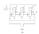
- FIG. 1 illustrates an embodiment of an arrangement for disconnecting one or more battery modules of an automotive battery.
- An automotive battery 10 comprising three serially connected battery modules 11, 12, 13 is located in an electric or hybrid vehicle for delivering power to a load in the form of an electric motor (not shown).
- the arrangement comprises a device 14 arranged to detect that one or more battery modules are to be disconnected.
- This device 14 may be embodied in the form of an electronic control unit (ECU) as previously discussed, which typically is implemented by one or more microprocessors executing appropriate software for controlling various systems and components in the electric vehicle.
- the ECU 14 may detect that one or a multiple selection of the battery modules should be disconnected (for instance as a consequence of a vehicle crash or an internal failure during e.g.
- the ECU 14 is assumed to detect that the first battery module 11 for some reason is faulty and should be disconnected. The driver of the vehicle will still be able to move the car in spite of the reduced power delivery capacity of the battery 10.
- a bypass switch 15, 16, 17 is arranged at each battery module and is controllable to bypass the respective battery module 11, 12, 13 via a bypass path 18, 19, 20.
- the ECU 14 detects that the first battery module 11 is faulty and should be disconnected.
- the ECU 14 send a control signal to the bypass switch 15 arranged at the first battery module 11 to close the bypass path 18. As previously mentioned, this may be performed by having a pyrotechnic charge move a bridging element upon ignition to close the bypass path 18 to the main power delivery line 24 of the automotive battery 10.
- a disconnect switch 21, 22, 23 is arranged at each battery module and is controllable to disconnect the respective battery module 11, 12, 13 from the remaining battery modules.
- the ECU 14 After the ECU 14 has bypassed the first battery module 11, or simultaneously with the bypassing, it sends a control signal to the disconnect switch 21 to disconnect the first battery module 11.
- This may be performed by having a pyrotechnic switch break a conductive path between the positive terminal of the first battery module 11 and the main power delivery line 24 of the automotive battery 10. Since the potentially damaging current flows in the bypass path 18, a low-rated pyrotechnic switch can be used for disconnection.
- the detected battery module is bypassed and thereafter, the bypassed module is disconnected from the remaining battery modules in the automotive battery, or the bypassing and the disconnecting of the battery module is undertaken simultaneously.
- the bypassing of the detected battery module will have the kickback-current of the electric motor flow via the bypass path, and disconnection can be performed without the risk of causing arcing, thereby greatly improving the robustness of the battery.
- limited operation of the battery is provided such that a driver of the motor vehicle is given an opportunity to move her vehicle from a busy stretch of road or even drive the vehicle to a workshop.
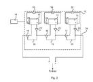
- FIG. 2 shows a further embodiment of an arrangement for disconnecting one or more battery modules of an automotive battery.
- the arrangement further comprises a discharge switch 25, 26, 27 and an energy draining device 28, 29, 39 in the form of e.g. a resistor arranged at each battery module 11, 12, 13.
- the discharge switch 25, e.g. a pyrotechnical switch, arranged at a disconnected battery module 11 is controllable to couple the disconnected battery module 11 to the energy draining device 28 such that the module is discharged.
- a faulty battery module can be discharged in a lenient manner to avoid any further direct and/ or delayed damage.
- a low-rated pyro switch can be used.
- FIG 3 shows a further embodiment of an arrangement for disconnecting one or more battery modules of an automotive battery.
- the arrangement further comprises current sensing means 31a, 32a, 33a realized by means of a coil arranged in the bypass path 18, 19, 20 of the respective battery module 11, 12, 13 and connected to the disconnect switch 21, 22, 23 of the respective battery module for controlling the disconnect switch.
- the coil 31a senses that the short-circuit current through the bypass path 18 reaches a predetermined level (vehicle and/ or battery dependent; could reach e.g. 1000 A in a truck), it will respond accordingly and control the disconnect switch 21 to disconnect the bypassed battery module 11.
- each of the current sensing means 31a, 32a, 33a is coupled to the respective discharge switch 25, 26, 27 for activating the discharge switch simultaneously as, or after, activation of the disconnect switch.
- the controlling of the disconnect switch 21 by means of the current sensing means 31a can be complemented with control signals from the ECU 14; in case the current flowing through the bypass path 18 is too low for the current sensing means 31a to react, the ECU could control the disconnect switch 21 to disconnect the battery module 11 from the main power delivery line 24 of the automotive battery 10.
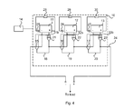
- FIG 4 shows an alternative embodiment to that illustrated in Figure 3 .
- the current sensing means 31b, 32b, 33b realized by means of coils are arranged at a terminal of the respective battery module 11, 12, 13 and connected to the bypass switch 15, 16, 17 of the respective battery module for controlling the bypass switch.
- the coil 31b senses that the current at a terminal (e.g. the positive terminal) of the battery module 11 reaches a predetermined level (vehicle and/ or battery dependent)
- the respective coil 31b, 32b, 33b will advantageously act as a device for detecting that a battery module is to be disconnected.
- each of the current sensing means 31b, 32b, 33b is coupled to the respective disconnect switch 21, 22, 23 for activating the disconnect switch simultaneously as, or after, activation of the bypass switch.
- the coil 31b senses that the current at the positive terminal of the battery module 11 reaches the predetermined level, it will respond by controlling the disconnect switch 21 to disconnect the battery module 11 from the main power supply line 24 of the automotive battery 10 either simultaneously as, or after, the bypass switch 15 has been controlled by the coil 31b to bypass the battery module 11 via the bypass path 18.
- each of the current sensing means 31b, 32b, 33b is coupled to the respective discharge switch 25, 26, 27 for activating the discharge switch simultaneously as, or after, activation of the disconnect switch.
- the coil 31b will further control discharge of the battery module 11 via the discharge switch 25 to the energy draining device 28 when the coil 31b senses an over-current at the positive terminal of the battery module 31b.
- An advantage of having the respective coil 31b, 32b, 33b control detection, bypass, disconnection and even discharge of the respective battery module 11, 12, 13 is that an ECU strictly not is required in the arrangement of the present invention.
- passive components and not having to included a component such as a microprocessor
- the arrangement for disconnecting one or more battery modules becomes inexpensive and less complex.
- the arrangement will be easier to implement inside the automotive battery with passive components.
- the arrangement of the present invention further comprises a delay circuit (not shown) at each battery module 11, 12,13 for delaying the control signal transmitted to the respective bypass switch 15, 16, 17 and/ or disconnect switch 21, 22 23 (and discharge switch 25, 26, 27).
- This delay circuit is preferably embodied by means of a passive component in the form of a capacitor, possibly supplemented with one or more resistors, in order to cause a delay of the control signal. This is advantageous in case disconnection is to be performed after bypassing. Further, by using passive components, the delay is completely autonomous. However, it is further possible that the control signal is delayed by one or more microprocessors (not shown) arranged locally at the automotive battery 10, or even by the ECU 14.
- a delay circuit could be dimensioned such that a control signal of a sufficient magnitude reaches the disconnect switch 21 ms after it reaches the bypass switch 15. In case a microprocessor is used, more advanced control is facilitated.
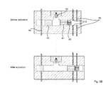
- Figures 5a-b illustrate the pyrotechnical switches according to embodiments of the present invention previously discussed.
- Figure 5a illustrates a pyrotechnical switch which combines connecting and disconnecting functionality. It is understood that pyrotechnical switches providing single functionality (connecting or disconnecting) can be used. However, such single functionality switches would each require their own charge for activation.
- the pyrotechnical switch of Figure 5a comprises a pyrotechnical charge 40, which when ignited activates a piston-like movable bridging element 41 closing a first conductive path 42. Hence, the bridging element 41 is conductive.
- a piston-like movable breaking element 43 opens a second conductive path 44.
- the breaking element 43 is hence isolating.
- the bypass switch 15, 16, 17 at each battery module 11, 12, 13 may be embodied by the bridging element 41 and the first conductive path 42, while the disconnect switch 21, 22, 23 at each battery module may be embodied by the breaking element 43 and the second conductive path 44, and combined in the same housing for each battery module along with a single charge 40.
- Figure 5b illustrates a pyrotechnical switch where the bypass switch 15, 16, 17, the disconnect switch 21, 22, 23 and the discharge switch 25, 26, 27 for the respective battery module 11, 12, 13 are combined in the same housing.
- the pyrotechnical charge 40 activates a first movable bridging element 41 closing a first conductive path 42 upon ignition by the control signal for bypassing a battery module.
- the movable breaking element 43 opens a second conductive path 44 for disconnecting the battery module.
- a second movable bridging element 45 closes a third conductive path 46 for discharging the battery module.
- switches in the form of relays can be used for any one of the bypass switches, disconnect switches and discharge switches, an advantage being e.g. that the switches can be selectably controlled to open and close (and subsequently to be closed and opened again).
- One or more disconnected modules could in that case be used as back-up in case these modules are functioning.
- FIG. 6 shows a flowchart of a method of disconnecting one or more battery modules in an automotive battery according to an embodiment of the present invention.
- a first step S101 it is detected that one or more battery modules are to be disconnected.
- step S102 the at least one detected battery module is bypassed.
- step S103 the at least one detected battery module is disconnected from remaining battery modules comprised in the automotive battery, either simultaneously as, or after, the bypassing. Hence, disconnection is performed no earlier than simultaneously as the bypassing.
- step S104 a further embodiment is indicated by step S104, where the detected battery module is discharged either simultaneously as, or after, the disconnection of the same.
- the vehicle can during this time be driven to a workshop if required.
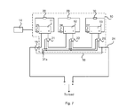
- Figure 7 shows an arrangement for bypassing all battery modules in an automotive battery according a further aspect of the present invention, where a single bypass switch is used to bypass all battery modules 11, 12, 13 from the main power delivery line 24 of the automotive battery 10 via a single bypass path 18.
- a single bypass switch is used to bypass all battery modules 11, 12, 13 from the main power delivery line 24 of the automotive battery 10 via a single bypass path 18.
- the single coil 31a senses the over-current in the bypass path 18 and controls the respective disconnect switch 21, 22, 23 to disconnect all battery modules either simultaneously as, or after, the bypassing.
- the vehicle cannot be driven since all power is removed from the electric motor.
- a current sensing means 31b, 32b, 33b could be arranged at a terminal of the respective battery module 11, 12, 13 for sensing an over-current and signalling to the single bypass switch 15 (and possibly to the respective disconnect switch 21, 22, 23) that the battery modules should be disconnected.
Landscapes
- Engineering & Computer Science (AREA)
- Power Engineering (AREA)
- Mechanical Engineering (AREA)
- Life Sciences & Earth Sciences (AREA)
- Sustainable Development (AREA)
- Sustainable Energy (AREA)
- Transportation (AREA)
- Chemical & Material Sciences (AREA)
- Manufacturing & Machinery (AREA)
- Combustion & Propulsion (AREA)
- Chemical Kinetics & Catalysis (AREA)
- Electrochemistry (AREA)
- General Chemical & Material Sciences (AREA)
- Secondary Cells (AREA)
- Charge And Discharge Circuits For Batteries Or The Like (AREA)
- Electric Propulsion And Braking For Vehicles (AREA)
- Protection Of Static Devices (AREA)
Priority Applications (6)
| Application Number | Priority Date | Filing Date | Title |
|---|---|---|---|
| EP13171050.1A EP2811548B1 (de) | 2013-06-07 | 2013-06-07 | Batteriemodul mit Trennanordnung |
| PCT/SE2014/050673 WO2014196917A1 (en) | 2013-06-07 | 2014-06-03 | Battery module disconnect arrangement |
| KR1020157034867A KR101891687B1 (ko) | 2013-06-07 | 2014-06-03 | 배터리 모듈 분리 장치 |
| US14/895,014 US9789782B2 (en) | 2013-06-07 | 2014-06-03 | Battery module disconnect arrangement |
| JP2016518302A JP6304784B2 (ja) | 2013-06-07 | 2014-06-03 | バッテリモジュール遮断構造 |
| CN201480032167.4A CN105263738B (zh) | 2013-06-07 | 2014-06-03 | 电池模块断开装置 |
Applications Claiming Priority (1)
| Application Number | Priority Date | Filing Date | Title |
|---|---|---|---|
| EP13171050.1A EP2811548B1 (de) | 2013-06-07 | 2013-06-07 | Batteriemodul mit Trennanordnung |
Publications (2)
| Publication Number | Publication Date |
|---|---|
| EP2811548A1 true EP2811548A1 (de) | 2014-12-10 |
| EP2811548B1 EP2811548B1 (de) | 2017-08-09 |
Family
ID=48570010
Family Applications (1)
| Application Number | Title | Priority Date | Filing Date |
|---|---|---|---|
| EP13171050.1A Active EP2811548B1 (de) | 2013-06-07 | 2013-06-07 | Batteriemodul mit Trennanordnung |
Country Status (6)
| Country | Link |
|---|---|
| US (1) | US9789782B2 (de) |
| EP (1) | EP2811548B1 (de) |
| JP (1) | JP6304784B2 (de) |
| KR (1) | KR101891687B1 (de) |
| CN (1) | CN105263738B (de) |
| WO (1) | WO2014196917A1 (de) |
Cited By (7)
| Publication number | Priority date | Publication date | Assignee | Title |
|---|---|---|---|---|
| WO2016113096A1 (de) * | 2015-01-13 | 2016-07-21 | Robert Bosch Gmbh | Batterie und batteriesystem aufweisend eine batterie |
| FR3063570A1 (fr) * | 2017-03-03 | 2018-09-07 | Mersen France Sb Sas | Dispositif de protection a double commande pour un circuit electrique et circuit electrique comprenant ce dispositif de protection |
| WO2019034474A1 (de) * | 2017-08-16 | 2019-02-21 | Volkswagen Aktiengesellschaft | Abschaltvorrichtung für ein elektrisches versorgungsnetz |
| WO2021040859A1 (en) * | 2019-08-28 | 2021-03-04 | Microsoft Technology Licensing, Llc | System and method for thermal cutoff protection device control from an external component |
| WO2021091497A1 (en) * | 2019-11-06 | 2021-05-14 | Nela Razvojni Center Za Elektroindustrijo In Elektroniko, D.O.O. | Switch for interruption of a direct current circuit powered by two electric voltage sources |
| EP3820009A4 (de) * | 2018-12-25 | 2022-03-23 | Suncall Corporation | Schutzsystem |
| EP3878697A4 (de) * | 2018-12-25 | 2022-06-08 | Suncall Corporation | Stromsperrsystem |
Families Citing this family (20)
| Publication number | Priority date | Publication date | Assignee | Title |
|---|---|---|---|---|
| KR101716185B1 (ko) * | 2012-06-18 | 2017-03-14 | 한화테크윈 주식회사 | 차량의 제어 방법, 및 이 방법을 채용한 차량 |
| US20150056480A1 (en) * | 2013-08-26 | 2015-02-26 | Lockheed Martin Corporation | Methods for dendrite detection and batteries containing dendrite sensors |
| DE102016113156B4 (de) * | 2016-07-18 | 2021-10-07 | Auto-Kabel Management Gmbh | Trennvorrichtung für eine Energieleitung und Verfahren zur Trennung einer Energieleitung |
| JP6696401B2 (ja) * | 2016-10-21 | 2020-05-20 | 株式会社デンソー | 電源装置 |
| DE102016222340A1 (de) * | 2016-11-15 | 2018-05-17 | Bayerische Motoren Werke Aktiengesellschaft | Sicherungsverfahren, Vorrichtung zu dessen Umsetzung und Hybrid- oder Elektro-Fahrzeug |
| JP6618455B2 (ja) * | 2016-11-28 | 2019-12-11 | 日立オートモティブシステムズ株式会社 | 電子制御装置、車載システム、および電源制御方法 |
| KR102371194B1 (ko) | 2017-04-07 | 2022-03-07 | 삼성에스디아이 주식회사 | 차량 구동용 전력 공급 시스템 |
| DE102017111652A1 (de) * | 2017-05-29 | 2018-11-29 | Hoppecke Advanced Battery Technology Gmbh | Sicherungssystem zum Schutz eines Batteriesystems |
| DE102018203915A1 (de) * | 2018-03-14 | 2019-09-19 | Audi Ag | HV-Energiespeicher |
| KR102518829B1 (ko) | 2018-05-08 | 2023-04-06 | 삼성에스디아이 주식회사 | 차량용 배터리팩 |
| KR102569634B1 (ko) | 2018-06-26 | 2023-08-22 | 주식회사 엘지에너지솔루션 | 모듈 보호 회로 및 이를 이용한 모듈 보호 방법 |
| KR102589023B1 (ko) * | 2018-10-10 | 2023-10-16 | 현대자동차주식회사 | 차량용 배터리 시스템 및 그 제어방법 |
| US20220144095A1 (en) * | 2019-06-25 | 2022-05-12 | Lg Energy Solution, Ltd. | Battery system |
| US11777150B2 (en) | 2019-08-28 | 2023-10-03 | SparkCharge, Inc. | Battery module |
| KR20220061221A (ko) * | 2019-10-31 | 2022-05-12 | 컨템포러리 엠퍼렉스 테크놀로지 씨오., 리미티드 | 배터리 모듈, 배터리 팩, 장치 및 고장 처리 방법 |
| JP7342657B2 (ja) * | 2019-11-28 | 2023-09-12 | 株式会社デンソー | 通信システム |
| WO2021201991A2 (en) | 2020-02-10 | 2021-10-07 | Wisk Aero Llc | Aircarft with pusher propeller |
| US11322966B1 (en) | 2021-01-27 | 2022-05-03 | Clenera, LLC | Power electronics-based battery management |
| EP4098493B1 (de) * | 2021-06-04 | 2024-02-14 | Aptiv Technologies Limited | Steuerungsvorrichtung und fahrzeugleistungverteilungsarchitektur damit |
| WO2023208336A1 (en) * | 2022-04-27 | 2023-11-02 | Hitachi Energy Switzerland Ag | An energy storage system |
Citations (5)
| Publication number | Priority date | Publication date | Assignee | Title |
|---|---|---|---|---|
| US6344788B1 (en) * | 1998-12-30 | 2002-02-05 | Pyroalliance | Pyrotechnically operated electrical contactor |
| WO2009106394A1 (de) | 2008-02-25 | 2009-09-03 | Robert Bosch Gmbh | Schutzsystem für batteriemodule |
| DE102010053942A1 (de) * | 2009-12-21 | 2011-06-22 | Schaeffler Technologies GmbH & Co. KG, 91074 | Abschalt- und Überbrückungsschaltung für ein Fahrzeug, insbesondere Elektrofahrzeug, umfassend eine Batterie mit Zellen, sowie Fahrzeug damit und Verfahren zum Ansteuern einer solchen |
| US20130088201A1 (en) * | 2010-04-23 | 2013-04-11 | Hitachi, Ltd. | Battery pack and battery pack controller |
| US20130126326A1 (en) * | 2009-11-27 | 2013-05-23 | Herakles | Electric switch having a slide and forming a short-circuit or selector switch |
Family Cites Families (27)
| Publication number | Priority date | Publication date | Assignee | Title |
|---|---|---|---|---|
| DE4406730A1 (de) | 1994-03-02 | 1995-09-14 | Bayern Chemie Gmbh Flugchemie | Vorrichtung zum Unterbrechen der Stromversorgung eines Kraftfahrzeuges bei einem Unfall |
| DE19503809B4 (de) * | 1995-02-06 | 2005-01-20 | Bayerische Motoren Werke Ag | Sicherungsvorrichtung für eine Stromleitung in Fahrzeugen |
| FR2770050B1 (fr) * | 1997-10-16 | 1999-12-10 | Alsthom Cge Alcatel | Dispositif de securite d'un accumulateur electrochimique |
| GB9820731D0 (en) | 1998-09-24 | 1998-11-18 | Delphi Automotive Systems Gmbh | Battery disconnection system |
| JP2000312442A (ja) * | 1999-04-23 | 2000-11-07 | Hitachi Ltd | 直列電池充放電装置 |
| JP3619720B2 (ja) * | 1999-10-22 | 2005-02-16 | 三洋電機株式会社 | 電源装置 |
| US6843157B2 (en) | 2002-06-13 | 2005-01-18 | Autoliv Asp, Inc. | Severing vehicle battery cable |
| US7498531B2 (en) | 2003-03-12 | 2009-03-03 | Delphi Technologies, Inc. | Housing and a conducting rail for disconnecting a battery |
| EP1469564B1 (de) | 2003-04-17 | 2012-12-05 | Autoliv Development AB | Pyromechanisches Batteriepol-Trennelement |
| ATE376163T1 (de) | 2003-04-30 | 2007-11-15 | Delphi Tech Inc | Gehäuse für eine pyromechanische trennvorrichtung mit integriertem anzündelement |
| US7339347B2 (en) * | 2003-08-11 | 2008-03-04 | Reserve Power Cell, Llc | Apparatus and method for reliably supplying electrical energy to an electrical system |
| JP4116609B2 (ja) * | 2004-11-04 | 2008-07-09 | パナソニックEvエナジー株式会社 | 電源制御装置、電動車両および電池制御ユニット |
| EP1742280B1 (de) | 2005-06-27 | 2014-12-24 | Delphi Technologies, Inc. | Anschlusseinheit zum Verbinden von elektrischen Komponenten mit einer Kraftfahrzeugbatterie |
| CN101675555B (zh) * | 2007-05-18 | 2012-09-12 | 松下电器产业株式会社 | 组电池及电池系统 |
| KR101042768B1 (ko) * | 2008-06-03 | 2011-06-20 | 삼성에스디아이 주식회사 | 배터리 팩 및 그 충전 방법 |
| JP5422810B2 (ja) * | 2009-03-26 | 2014-02-19 | 株式会社Nttファシリティーズ | 予備電源システム及び予備電源システム保護方法 |
| FR2944161A1 (fr) * | 2009-04-02 | 2010-10-08 | Vehicules Electr Soc D | Procede de securisation du fonctionnement d'une batterie electrique |
| US20100305792A1 (en) * | 2009-05-29 | 2010-12-02 | Ise Corporation | Dynamically Reconfigurable High Power Energy Storage for Hybrid Vehicles |
| JP5359982B2 (ja) | 2009-06-29 | 2013-12-04 | 豊田合成株式会社 | 車両の電気回路遮断装置 |
| GB2475326A (en) | 2009-11-16 | 2011-05-18 | Autoliv Dev | Inflatable battery protector |
| EP2355229A1 (de) * | 2010-02-08 | 2011-08-10 | Fortu Intellectual Property AG | Hochstrombatteriesystem und Verfahren zur Steuerung eines Hochstrombatteriesystems |
| JP2011217428A (ja) * | 2010-03-31 | 2011-10-27 | Honda Motor Co Ltd | 電動移動体用の蓄電池システム、および電気自動車 |
| DE102010015239A1 (de) | 2010-04-15 | 2011-10-20 | Auto-Kabel Managementgesellschaft Mbh | Stromunterbrecher für eine Energieleitung |
| US9024586B2 (en) * | 2010-10-14 | 2015-05-05 | GM Global Technology Operations LLC | Battery fault tolerant architecture for cell failure modes series bypass circuit |
| US9184605B2 (en) * | 2011-03-28 | 2015-11-10 | Changs Ascending Enterprise Co., Ltd. | High voltage battery system for vehicle applications |
| DE102011117474A1 (de) | 2011-11-02 | 2013-05-02 | Li-Tec Battery Gmbh | Energiespeicherzelle und Energiespeichervorrichtung mit mehreren solchen Energiespeicherzellen |
| EP2597764B1 (de) * | 2011-11-22 | 2016-04-13 | ABB Technology AG | Verfahren zur Behandlung von Fehlern in einem modularen Multilevelumrichter sowie ein solcher Umrichter |
-
2013
- 2013-06-07 EP EP13171050.1A patent/EP2811548B1/de active Active
-
2014
- 2014-06-03 US US14/895,014 patent/US9789782B2/en active Active
- 2014-06-03 KR KR1020157034867A patent/KR101891687B1/ko active IP Right Grant
- 2014-06-03 CN CN201480032167.4A patent/CN105263738B/zh active Active
- 2014-06-03 JP JP2016518302A patent/JP6304784B2/ja active Active
- 2014-06-03 WO PCT/SE2014/050673 patent/WO2014196917A1/en active Application Filing
Patent Citations (5)
| Publication number | Priority date | Publication date | Assignee | Title |
|---|---|---|---|---|
| US6344788B1 (en) * | 1998-12-30 | 2002-02-05 | Pyroalliance | Pyrotechnically operated electrical contactor |
| WO2009106394A1 (de) | 2008-02-25 | 2009-09-03 | Robert Bosch Gmbh | Schutzsystem für batteriemodule |
| US20130126326A1 (en) * | 2009-11-27 | 2013-05-23 | Herakles | Electric switch having a slide and forming a short-circuit or selector switch |
| DE102010053942A1 (de) * | 2009-12-21 | 2011-06-22 | Schaeffler Technologies GmbH & Co. KG, 91074 | Abschalt- und Überbrückungsschaltung für ein Fahrzeug, insbesondere Elektrofahrzeug, umfassend eine Batterie mit Zellen, sowie Fahrzeug damit und Verfahren zum Ansteuern einer solchen |
| US20130088201A1 (en) * | 2010-04-23 | 2013-04-11 | Hitachi, Ltd. | Battery pack and battery pack controller |
Cited By (8)
| Publication number | Priority date | Publication date | Assignee | Title |
|---|---|---|---|---|
| WO2016113096A1 (de) * | 2015-01-13 | 2016-07-21 | Robert Bosch Gmbh | Batterie und batteriesystem aufweisend eine batterie |
| FR3063570A1 (fr) * | 2017-03-03 | 2018-09-07 | Mersen France Sb Sas | Dispositif de protection a double commande pour un circuit electrique et circuit electrique comprenant ce dispositif de protection |
| WO2019034474A1 (de) * | 2017-08-16 | 2019-02-21 | Volkswagen Aktiengesellschaft | Abschaltvorrichtung für ein elektrisches versorgungsnetz |
| EP3820009A4 (de) * | 2018-12-25 | 2022-03-23 | Suncall Corporation | Schutzsystem |
| EP3878697A4 (de) * | 2018-12-25 | 2022-06-08 | Suncall Corporation | Stromsperrsystem |
| WO2021040859A1 (en) * | 2019-08-28 | 2021-03-04 | Microsoft Technology Licensing, Llc | System and method for thermal cutoff protection device control from an external component |
| US11509159B2 (en) | 2019-08-28 | 2022-11-22 | Microsoft Technology Licensing, Llc | System and method for thermal cutoff protection device control from an external component |
| WO2021091497A1 (en) * | 2019-11-06 | 2021-05-14 | Nela Razvojni Center Za Elektroindustrijo In Elektroniko, D.O.O. | Switch for interruption of a direct current circuit powered by two electric voltage sources |
Also Published As
| Publication number | Publication date |
|---|---|
| CN105263738A (zh) | 2016-01-20 |
| KR101891687B1 (ko) | 2018-09-28 |
| WO2014196917A1 (en) | 2014-12-11 |
| JP2016524895A (ja) | 2016-08-18 |
| US9789782B2 (en) | 2017-10-17 |
| JP6304784B2 (ja) | 2018-04-04 |
| CN105263738B (zh) | 2019-05-14 |
| KR20160013900A (ko) | 2016-02-05 |
| US20160114695A1 (en) | 2016-04-28 |
| EP2811548B1 (de) | 2017-08-09 |
Similar Documents
| Publication | Publication Date | Title |
|---|---|---|
| US9789782B2 (en) | Battery module disconnect arrangement | |
| EP2607178B1 (de) | Stromversorgung zum Versorgen einer elektrischen Last eines Fahrzeugs | |
| US10328801B2 (en) | Electrical fuse, method of operating an electrical fuse and electrical traction network | |
| EP2448081B1 (de) | Batteriepack-Überladungsschutzsystem | |
| US11440412B2 (en) | Disconnection device for a high-voltage electrical system of a motor vehicle, high-voltage electrical system, and motor vehicle | |
| EP2811549B1 (de) | Auf Überstrom reagierende Vorrichtung | |
| CN106030951B (zh) | 电池组系统和用于运行这样的电池组系统的方法 | |
| EP2631969B1 (de) | Batteriepack für ein Fahrzeug | |
| EP2684729B1 (de) | Kontaktanordnung für eine sichere Trennung einer Stromversorgung in einem Fahrzeug | |
| CN110271433B (zh) | 可动态切断的电池系统、用于运行其的方法以及机动车 | |
| CN109070756B (zh) | 包括保险装置的高压电池系统 | |
| US11862422B2 (en) | Electrical fuse, method for operating an electrical fuse, and electrical traction network | |
| CN101836319A (zh) | 包括至少一个燃料电池的燃料电池系统 | |
| CN110789348A (zh) | 牵引电网和用于在短路情况下运行牵引电网的方法 | |
| CN108688472B (zh) | 保险装置,具有保险装置的机动车和运行保险装置的方法 | |
| EP4123858B1 (de) | Batterieverwaltungssystem und verfahren zur überwachung von überstrom in einem batterieverwaltungssystem | |
| CN113039693A (zh) | 用于电化学的蓄能系统的分开装置 | |
| WO2023145465A1 (ja) | 車載電源システム | |
| EP4166371A1 (de) | Elektro- oder hybridfahrzeug mit einem sicherheitssystem für die elektrische sicherheit | |
| US20230132671A1 (en) | Control device, motor vehicle and method for activating an active discharge circuit | |
| CN116829399A (zh) | 用于至少部分电动的机动车的车载电网的监测装置以及方法 | |
| CN113690840A (zh) | 用于机动车的车载电网的电气保护的方法和机动车 | |
| KR20200059460A (ko) | 고전력 시스템의 릴레이 스위치 정상동작 검침 장치 및 방법 |
Legal Events
| Date | Code | Title | Description |
|---|---|---|---|
| PUAI | Public reference made under article 153(3) epc to a published international application that has entered the european phase |
Free format text: ORIGINAL CODE: 0009012 |
|
| 17P | Request for examination filed |
Effective date: 20130607 |
|
| AK | Designated contracting states |
Kind code of ref document: A1 Designated state(s): AL AT BE BG CH CY CZ DE DK EE ES FI FR GB GR HR HU IE IS IT LI LT LU LV MC MK MT NL NO PL PT RO RS SE SI SK SM TR |
|
| AX | Request for extension of the european patent |
Extension state: BA ME |
|
| R17P | Request for examination filed (corrected) |
Effective date: 20150413 |
|
| RBV | Designated contracting states (corrected) |
Designated state(s): AL AT BE BG CH CY CZ DE DK EE ES FI FR GB GR HR HU IE IS IT LI LT LU LV MC MK MT NL NO PL PT RO RS SE SI SK SM TR |
|
| RIC1 | Information provided on ipc code assigned before grant |
Ipc: B60L 3/00 20060101ALI20161208BHEP Ipc: H02J 7/00 20060101ALI20161208BHEP Ipc: H01M 10/48 20060101ALI20161208BHEP Ipc: H01M 2/20 20060101ALI20161208BHEP Ipc: H01M 2/34 20060101AFI20161208BHEP Ipc: H01H 37/76 20060101ALI20161208BHEP Ipc: H01H 39/00 20060101ALI20161208BHEP Ipc: B60L 11/18 20060101ALI20161208BHEP Ipc: B60L 3/04 20060101ALI20161208BHEP |
|
| GRAP | Despatch of communication of intention to grant a patent |
Free format text: ORIGINAL CODE: EPIDOSNIGR1 |
|
| INTG | Intention to grant announced |
Effective date: 20170207 |
|
| GRAS | Grant fee paid |
Free format text: ORIGINAL CODE: EPIDOSNIGR3 |
|
| GRAA | (expected) grant |
Free format text: ORIGINAL CODE: 0009210 |
|
| AK | Designated contracting states |
Kind code of ref document: B1 Designated state(s): AL AT BE BG CH CY CZ DE DK EE ES FI FR GB GR HR HU IE IS IT LI LT LU LV MC MK MT NL NO PL PT RO RS SE SI SK SM TR |
|
| REG | Reference to a national code |
Ref country code: GB Ref legal event code: FG4D |
|
| REG | Reference to a national code |
Ref country code: CH Ref legal event code: EP Ref country code: AT Ref legal event code: REF Ref document number: 917722 Country of ref document: AT Kind code of ref document: T Effective date: 20170815 |
|
| REG | Reference to a national code |
Ref country code: IE Ref legal event code: FG4D |
|
| REG | Reference to a national code |
Ref country code: DE Ref legal event code: R096 Ref document number: 602013024644 Country of ref document: DE |
|
| REG | Reference to a national code |
Ref country code: NL Ref legal event code: MP Effective date: 20170809 |
|
| REG | Reference to a national code |
Ref country code: LT Ref legal event code: MG4D |
|
| REG | Reference to a national code |
Ref country code: AT Ref legal event code: MK05 Ref document number: 917722 Country of ref document: AT Kind code of ref document: T Effective date: 20170809 |
|
| PG25 | Lapsed in a contracting state [announced via postgrant information from national office to epo] |
Ref country code: NL Free format text: LAPSE BECAUSE OF FAILURE TO SUBMIT A TRANSLATION OF THE DESCRIPTION OR TO PAY THE FEE WITHIN THE PRESCRIBED TIME-LIMIT Effective date: 20170809 Ref country code: NO Free format text: LAPSE BECAUSE OF FAILURE TO SUBMIT A TRANSLATION OF THE DESCRIPTION OR TO PAY THE FEE WITHIN THE PRESCRIBED TIME-LIMIT Effective date: 20171109 Ref country code: AT Free format text: LAPSE BECAUSE OF FAILURE TO SUBMIT A TRANSLATION OF THE DESCRIPTION OR TO PAY THE FEE WITHIN THE PRESCRIBED TIME-LIMIT Effective date: 20170809 Ref country code: SE Free format text: LAPSE BECAUSE OF FAILURE TO SUBMIT A TRANSLATION OF THE DESCRIPTION OR TO PAY THE FEE WITHIN THE PRESCRIBED TIME-LIMIT Effective date: 20170809 Ref country code: FI Free format text: LAPSE BECAUSE OF FAILURE TO SUBMIT A TRANSLATION OF THE DESCRIPTION OR TO PAY THE FEE WITHIN THE PRESCRIBED TIME-LIMIT Effective date: 20170809 Ref country code: LT Free format text: LAPSE BECAUSE OF FAILURE TO SUBMIT A TRANSLATION OF THE DESCRIPTION OR TO PAY THE FEE WITHIN THE PRESCRIBED TIME-LIMIT Effective date: 20170809 Ref country code: HR Free format text: LAPSE BECAUSE OF FAILURE TO SUBMIT A TRANSLATION OF THE DESCRIPTION OR TO PAY THE FEE WITHIN THE PRESCRIBED TIME-LIMIT Effective date: 20170809 |
|
| PG25 | Lapsed in a contracting state [announced via postgrant information from national office to epo] |
Ref country code: BG Free format text: LAPSE BECAUSE OF FAILURE TO SUBMIT A TRANSLATION OF THE DESCRIPTION OR TO PAY THE FEE WITHIN THE PRESCRIBED TIME-LIMIT Effective date: 20171109 Ref country code: GR Free format text: LAPSE BECAUSE OF FAILURE TO SUBMIT A TRANSLATION OF THE DESCRIPTION OR TO PAY THE FEE WITHIN THE PRESCRIBED TIME-LIMIT Effective date: 20171110 Ref country code: LV Free format text: LAPSE BECAUSE OF FAILURE TO SUBMIT A TRANSLATION OF THE DESCRIPTION OR TO PAY THE FEE WITHIN THE PRESCRIBED TIME-LIMIT Effective date: 20170809 Ref country code: ES Free format text: LAPSE BECAUSE OF FAILURE TO SUBMIT A TRANSLATION OF THE DESCRIPTION OR TO PAY THE FEE WITHIN THE PRESCRIBED TIME-LIMIT Effective date: 20170809 Ref country code: RS Free format text: LAPSE BECAUSE OF FAILURE TO SUBMIT A TRANSLATION OF THE DESCRIPTION OR TO PAY THE FEE WITHIN THE PRESCRIBED TIME-LIMIT Effective date: 20170809 Ref country code: PL Free format text: LAPSE BECAUSE OF FAILURE TO SUBMIT A TRANSLATION OF THE DESCRIPTION OR TO PAY THE FEE WITHIN THE PRESCRIBED TIME-LIMIT Effective date: 20170809 Ref country code: IS Free format text: LAPSE BECAUSE OF FAILURE TO SUBMIT A TRANSLATION OF THE DESCRIPTION OR TO PAY THE FEE WITHIN THE PRESCRIBED TIME-LIMIT Effective date: 20171209 |
|
| PG25 | Lapsed in a contracting state [announced via postgrant information from national office to epo] |
Ref country code: DK Free format text: LAPSE BECAUSE OF FAILURE TO SUBMIT A TRANSLATION OF THE DESCRIPTION OR TO PAY THE FEE WITHIN THE PRESCRIBED TIME-LIMIT Effective date: 20170809 Ref country code: CZ Free format text: LAPSE BECAUSE OF FAILURE TO SUBMIT A TRANSLATION OF THE DESCRIPTION OR TO PAY THE FEE WITHIN THE PRESCRIBED TIME-LIMIT Effective date: 20170809 Ref country code: RO Free format text: LAPSE BECAUSE OF FAILURE TO SUBMIT A TRANSLATION OF THE DESCRIPTION OR TO PAY THE FEE WITHIN THE PRESCRIBED TIME-LIMIT Effective date: 20170809 |
|
| REG | Reference to a national code |
Ref country code: DE Ref legal event code: R097 Ref document number: 602013024644 Country of ref document: DE |
|
| PG25 | Lapsed in a contracting state [announced via postgrant information from national office to epo] |
Ref country code: SK Free format text: LAPSE BECAUSE OF FAILURE TO SUBMIT A TRANSLATION OF THE DESCRIPTION OR TO PAY THE FEE WITHIN THE PRESCRIBED TIME-LIMIT Effective date: 20170809 Ref country code: IT Free format text: LAPSE BECAUSE OF FAILURE TO SUBMIT A TRANSLATION OF THE DESCRIPTION OR TO PAY THE FEE WITHIN THE PRESCRIBED TIME-LIMIT Effective date: 20170809 Ref country code: EE Free format text: LAPSE BECAUSE OF FAILURE TO SUBMIT A TRANSLATION OF THE DESCRIPTION OR TO PAY THE FEE WITHIN THE PRESCRIBED TIME-LIMIT Effective date: 20170809 Ref country code: SM Free format text: LAPSE BECAUSE OF FAILURE TO SUBMIT A TRANSLATION OF THE DESCRIPTION OR TO PAY THE FEE WITHIN THE PRESCRIBED TIME-LIMIT Effective date: 20170809 |
|
| PLBE | No opposition filed within time limit |
Free format text: ORIGINAL CODE: 0009261 |
|
| STAA | Information on the status of an ep patent application or granted ep patent |
Free format text: STATUS: NO OPPOSITION FILED WITHIN TIME LIMIT |
|
| REG | Reference to a national code |
Ref country code: FR Ref legal event code: PLFP Year of fee payment: 6 |
|
| 26N | No opposition filed |
Effective date: 20180511 |
|
| PG25 | Lapsed in a contracting state [announced via postgrant information from national office to epo] |
Ref country code: SI Free format text: LAPSE BECAUSE OF FAILURE TO SUBMIT A TRANSLATION OF THE DESCRIPTION OR TO PAY THE FEE WITHIN THE PRESCRIBED TIME-LIMIT Effective date: 20170809 |
|
| REG | Reference to a national code |
Ref country code: CH Ref legal event code: PL |
|
| GBPC | Gb: european patent ceased through non-payment of renewal fee |
Effective date: 20180607 |
|
| REG | Reference to a national code |
Ref country code: BE Ref legal event code: MM Effective date: 20180630 |
|
| REG | Reference to a national code |
Ref country code: IE Ref legal event code: MM4A |
|
| PG25 | Lapsed in a contracting state [announced via postgrant information from national office to epo] |
Ref country code: LU Free format text: LAPSE BECAUSE OF NON-PAYMENT OF DUE FEES Effective date: 20180607 Ref country code: MC Free format text: LAPSE BECAUSE OF FAILURE TO SUBMIT A TRANSLATION OF THE DESCRIPTION OR TO PAY THE FEE WITHIN THE PRESCRIBED TIME-LIMIT Effective date: 20170809 |
|
| PG25 | Lapsed in a contracting state [announced via postgrant information from national office to epo] |
Ref country code: GB Free format text: LAPSE BECAUSE OF NON-PAYMENT OF DUE FEES Effective date: 20180607 Ref country code: CH Free format text: LAPSE BECAUSE OF NON-PAYMENT OF DUE FEES Effective date: 20180630 Ref country code: IE Free format text: LAPSE BECAUSE OF NON-PAYMENT OF DUE FEES Effective date: 20180607 Ref country code: LI Free format text: LAPSE BECAUSE OF NON-PAYMENT OF DUE FEES Effective date: 20180630 |
|
| PG25 | Lapsed in a contracting state [announced via postgrant information from national office to epo] |
Ref country code: BE Free format text: LAPSE BECAUSE OF NON-PAYMENT OF DUE FEES Effective date: 20180630 |
|
| PG25 | Lapsed in a contracting state [announced via postgrant information from national office to epo] |
Ref country code: MT Free format text: LAPSE BECAUSE OF NON-PAYMENT OF DUE FEES Effective date: 20180607 |
|
| PG25 | Lapsed in a contracting state [announced via postgrant information from national office to epo] |
Ref country code: TR Free format text: LAPSE BECAUSE OF FAILURE TO SUBMIT A TRANSLATION OF THE DESCRIPTION OR TO PAY THE FEE WITHIN THE PRESCRIBED TIME-LIMIT Effective date: 20170809 |
|
| PG25 | Lapsed in a contracting state [announced via postgrant information from national office to epo] |
Ref country code: HU Free format text: LAPSE BECAUSE OF FAILURE TO SUBMIT A TRANSLATION OF THE DESCRIPTION OR TO PAY THE FEE WITHIN THE PRESCRIBED TIME-LIMIT; INVALID AB INITIO Effective date: 20130607 Ref country code: PT Free format text: LAPSE BECAUSE OF FAILURE TO SUBMIT A TRANSLATION OF THE DESCRIPTION OR TO PAY THE FEE WITHIN THE PRESCRIBED TIME-LIMIT Effective date: 20170809 |
|
| PG25 | Lapsed in a contracting state [announced via postgrant information from national office to epo] |
Ref country code: MK Free format text: LAPSE BECAUSE OF NON-PAYMENT OF DUE FEES Effective date: 20170809 Ref country code: CY Free format text: LAPSE BECAUSE OF FAILURE TO SUBMIT A TRANSLATION OF THE DESCRIPTION OR TO PAY THE FEE WITHIN THE PRESCRIBED TIME-LIMIT Effective date: 20170809 |
|
| PG25 | Lapsed in a contracting state [announced via postgrant information from national office to epo] |
Ref country code: AL Free format text: LAPSE BECAUSE OF FAILURE TO SUBMIT A TRANSLATION OF THE DESCRIPTION OR TO PAY THE FEE WITHIN THE PRESCRIBED TIME-LIMIT Effective date: 20170809 |
|
| REG | Reference to a national code |
Ref country code: DE Ref legal event code: R079 Ref document number: 602013024644 Country of ref document: DE Free format text: PREVIOUS MAIN CLASS: H01M0002340000 Ipc: H01M0050572000 |
|
| P01 | Opt-out of the competence of the unified patent court (upc) registered |
Effective date: 20230507 |
|
| PGFP | Annual fee paid to national office [announced via postgrant information from national office to epo] |
Ref country code: FR Payment date: 20230623 Year of fee payment: 11 Ref country code: DE Payment date: 20230620 Year of fee payment: 11 |