EP2811546B1 - Blei-Säureakkumulator - Google Patents
Blei-Säureakkumulator Download PDFInfo
- Publication number
- EP2811546B1 EP2811546B1 EP14171546.6A EP14171546A EP2811546B1 EP 2811546 B1 EP2811546 B1 EP 2811546B1 EP 14171546 A EP14171546 A EP 14171546A EP 2811546 B1 EP2811546 B1 EP 2811546B1
- Authority
- EP
- European Patent Office
- Prior art keywords
- separator
- electrode plate
- lead
- storage battery
- acid storage
- Prior art date
- Legal status (The legal status is an assumption and is not a legal conclusion. Google has not performed a legal analysis and makes no representation as to the accuracy of the status listed.)
- Active
Links
- 239000002253 acid Substances 0.000 title claims description 42
- 238000003860 storage Methods 0.000 title claims description 42
- 239000011521 glass Substances 0.000 claims description 7
- 230000001105 regulatory effect Effects 0.000 claims description 4
- 238000005304 joining Methods 0.000 claims description 3
- 239000000835 fiber Substances 0.000 claims description 2
- 239000011149 active material Substances 0.000 description 22
- 239000004698 Polyethylene Substances 0.000 description 4
- 239000008151 electrolyte solution Substances 0.000 description 4
- -1 polyethylene Polymers 0.000 description 4
- 229920000573 polyethylene Polymers 0.000 description 4
- 238000003780 insertion Methods 0.000 description 3
- 230000037431 insertion Effects 0.000 description 3
- 229910000882 Ca alloy Inorganic materials 0.000 description 2
- 238000000034 method Methods 0.000 description 2
- 238000005192 partition Methods 0.000 description 2
- QAOWNCQODCNURD-UHFFFAOYSA-N Sulfuric acid Chemical compound OS(O)(=O)=O QAOWNCQODCNURD-UHFFFAOYSA-N 0.000 description 1
- 230000002745 absorbent Effects 0.000 description 1
- 239000002250 absorbent Substances 0.000 description 1
- 230000006835 compression Effects 0.000 description 1
- 238000007906 compression Methods 0.000 description 1
- 230000000694 effects Effects 0.000 description 1
- YADSGOSSYOOKMP-UHFFFAOYSA-N lead dioxide Inorganic materials O=[Pb]=O YADSGOSSYOOKMP-UHFFFAOYSA-N 0.000 description 1
- 239000007773 negative electrode material Substances 0.000 description 1
- 230000002093 peripheral effect Effects 0.000 description 1
- 239000007774 positive electrode material Substances 0.000 description 1
- 238000003825 pressing Methods 0.000 description 1
- 230000002265 prevention Effects 0.000 description 1
- 238000004080 punching Methods 0.000 description 1
- 238000009958 sewing Methods 0.000 description 1
Images


Classifications
-
- H—ELECTRICITY
- H01—ELECTRIC ELEMENTS
- H01M—PROCESSES OR MEANS, e.g. BATTERIES, FOR THE DIRECT CONVERSION OF CHEMICAL ENERGY INTO ELECTRICAL ENERGY
- H01M10/00—Secondary cells; Manufacture thereof
- H01M10/06—Lead-acid accumulators
-
- H—ELECTRICITY
- H01—ELECTRIC ELEMENTS
- H01M—PROCESSES OR MEANS, e.g. BATTERIES, FOR THE DIRECT CONVERSION OF CHEMICAL ENERGY INTO ELECTRICAL ENERGY
- H01M50/00—Constructional details or processes of manufacture of the non-active parts of electrochemical cells other than fuel cells, e.g. hybrid cells
- H01M50/10—Primary casings; Jackets or wrappings
- H01M50/102—Primary casings; Jackets or wrappings characterised by their shape or physical structure
- H01M50/112—Monobloc comprising multiple compartments
- H01M50/114—Monobloc comprising multiple compartments specially adapted for lead-acid cells
-
- H—ELECTRICITY
- H01—ELECTRIC ELEMENTS
- H01M—PROCESSES OR MEANS, e.g. BATTERIES, FOR THE DIRECT CONVERSION OF CHEMICAL ENERGY INTO ELECTRICAL ENERGY
- H01M50/00—Constructional details or processes of manufacture of the non-active parts of electrochemical cells other than fuel cells, e.g. hybrid cells
- H01M50/40—Separators; Membranes; Diaphragms; Spacing elements inside cells
- H01M50/409—Separators, membranes or diaphragms characterised by the material
- H01M50/431—Inorganic material
- H01M50/434—Ceramics
- H01M50/437—Glass
-
- H—ELECTRICITY
- H01—ELECTRIC ELEMENTS
- H01M—PROCESSES OR MEANS, e.g. BATTERIES, FOR THE DIRECT CONVERSION OF CHEMICAL ENERGY INTO ELECTRICAL ENERGY
- H01M50/00—Constructional details or processes of manufacture of the non-active parts of electrochemical cells other than fuel cells, e.g. hybrid cells
- H01M50/40—Separators; Membranes; Diaphragms; Spacing elements inside cells
- H01M50/409—Separators, membranes or diaphragms characterised by the material
- H01M50/44—Fibrous material
-
- H—ELECTRICITY
- H01—ELECTRIC ELEMENTS
- H01M—PROCESSES OR MEANS, e.g. BATTERIES, FOR THE DIRECT CONVERSION OF CHEMICAL ENERGY INTO ELECTRICAL ENERGY
- H01M50/00—Constructional details or processes of manufacture of the non-active parts of electrochemical cells other than fuel cells, e.g. hybrid cells
- H01M50/40—Separators; Membranes; Diaphragms; Spacing elements inside cells
- H01M50/463—Separators, membranes or diaphragms characterised by their shape
- H01M50/466—U-shaped, bag-shaped or folded
-
- H—ELECTRICITY
- H01—ELECTRIC ELEMENTS
- H01M—PROCESSES OR MEANS, e.g. BATTERIES, FOR THE DIRECT CONVERSION OF CHEMICAL ENERGY INTO ELECTRICAL ENERGY
- H01M10/00—Secondary cells; Manufacture thereof
- H01M10/06—Lead-acid accumulators
- H01M10/12—Construction or manufacture
- H01M10/121—Valve regulated lead acid batteries [VRLA]
-
- H—ELECTRICITY
- H01—ELECTRIC ELEMENTS
- H01M—PROCESSES OR MEANS, e.g. BATTERIES, FOR THE DIRECT CONVERSION OF CHEMICAL ENERGY INTO ELECTRICAL ENERGY
- H01M2220/00—Batteries for particular applications
- H01M2220/20—Batteries in motive systems, e.g. vehicle, ship, plane
-
- H—ELECTRICITY
- H01—ELECTRIC ELEMENTS
- H01M—PROCESSES OR MEANS, e.g. BATTERIES, FOR THE DIRECT CONVERSION OF CHEMICAL ENERGY INTO ELECTRICAL ENERGY
- H01M50/00—Constructional details or processes of manufacture of the non-active parts of electrochemical cells other than fuel cells, e.g. hybrid cells
- H01M50/50—Current conducting connections for cells or batteries
-
- Y—GENERAL TAGGING OF NEW TECHNOLOGICAL DEVELOPMENTS; GENERAL TAGGING OF CROSS-SECTIONAL TECHNOLOGIES SPANNING OVER SEVERAL SECTIONS OF THE IPC; TECHNICAL SUBJECTS COVERED BY FORMER USPC CROSS-REFERENCE ART COLLECTIONS [XRACs] AND DIGESTS
- Y02—TECHNOLOGIES OR APPLICATIONS FOR MITIGATION OR ADAPTATION AGAINST CLIMATE CHANGE
- Y02E—REDUCTION OF GREENHOUSE GAS [GHG] EMISSIONS, RELATED TO ENERGY GENERATION, TRANSMISSION OR DISTRIBUTION
- Y02E60/00—Enabling technologies; Technologies with a potential or indirect contribution to GHG emissions mitigation
- Y02E60/10—Energy storage using batteries
-
- Y—GENERAL TAGGING OF NEW TECHNOLOGICAL DEVELOPMENTS; GENERAL TAGGING OF CROSS-SECTIONAL TECHNOLOGIES SPANNING OVER SEVERAL SECTIONS OF THE IPC; TECHNICAL SUBJECTS COVERED BY FORMER USPC CROSS-REFERENCE ART COLLECTIONS [XRACs] AND DIGESTS
- Y02—TECHNOLOGIES OR APPLICATIONS FOR MITIGATION OR ADAPTATION AGAINST CLIMATE CHANGE
- Y02P—CLIMATE CHANGE MITIGATION TECHNOLOGIES IN THE PRODUCTION OR PROCESSING OF GOODS
- Y02P70/00—Climate change mitigation technologies in the production process for final industrial or consumer products
- Y02P70/50—Manufacturing or production processes characterised by the final manufactured product
Definitions
- the present invention relates to a lead-acid storage battery according to the preamble of claim 1 which is known from WO 2012/048885 A1 .
- lead-acid storage batteries used in various fields such as automobiles, there is one including positive electrode plates and negative electrode plates layered alternately with separators interposed therebetween in a container.
- a lead-acid storage battery as disclosed in JP-A-2004-311357 , in which a separator protrudes farther than outer peripheral edges of plates in order to prevent a short circuit caused by elongation of the positive electrode plate.
- the lead-acid storage battery in JP-A-2004-311357 is still susceptible to improvement in prevention of the short circuit between the positive electrode plate and the negative electrode plate due to elongation of the positive electrode plate.
- the fallen active materials may cause a short circuit between the positive electrode plate and the negative electrode plate.
- the fallen active materials accumulate between end portions of the separator and inner walls of the container to cause the short circuit between the positive electrode plate and the negative electrode plate.
- a lead-acid storage battery including a container housing an element formed by alternately layering a positive electrode plate and a negative electrode plate with a deformable separator interposed therebetween, wherein the container includes a narrow portion having a small inside dimension in a width direction intersecting a layered direction of the element, a width of each of the plates is smaller than the inside dimension in the width direction of the narrow portion of the container, and a width of the separator is greater than or equal to the inside dimension of the narrow portion of the container.
- the separator is compressed on opposite sides of the respective plates in the narrow portion.
- the separator fills clearances between the respective plates and the container and the positive electrode plate and the negative electrode plate can be fixed to the container with large retaining force. Therefore, it is possible to suppress falling off of active materials due to vibrations and the like.
- the separator having the greater width than the plates serves as a separating wall for separating the positive electrode plate and the negative electrode plate from each other in the container. Therefore, the short circuit between the plates due to elongation of the positive electrode plate or the negative electrode plate can be reliably suppressed and the short circuit between the plates due to the active materials which have fallen off from the plates can be suppressed.
- the separator may have such a width as to come in contact with inner faces of a portion of the container adjacent to the narrow portion. In this way, it is possible to more reliably separate the positive electrode plate and the negative electrode plate from each other in the container to thereby more reliably suppress the short circuit between the plates due to elongation of the positive electrode plate or the negative electrode plate.
- the separator may be an elastically deformable glass mat and the width of the separator may be greater than or equal to the inside dimension of the narrow portion of the container and smaller than an inside dimension in the width direction of the portion of the container adjacent to the narrow portion.
- the separator is the glass mat which can be elastically deformed by compression, the separator has higher elasticity than a separator made of polyethylene, for example, and can fix the positive electrode plate and the negative electrode plate to the container with larger retaining force. Therefore, it is possible to further suppress falling off of the active materials due to vibrations and the like.
- the separator formed by the glass mat is more liable to get damaged while rubbing against the container when the element is housed in the container, as compared with the separator made of polyethylene, for example, the width of the separator is smaller than the inside dimension in the width direction of the portion of the container adjacent to the narrow portion and therefore it is possible to suppress the damage due to rubbing against the container.
- the container may be in a rectangular parallelepiped shape with one side open and the narrow portion may be formed at an end portion of the container on an opposite side from the opening. In this way, it is easy to insert the element into the container, which improves workability and suppresses damage to the separator due to rubbing of the separator against the container during the insertion. Furthermore, it is possible to enhance stability of the respective plates and the separator in disposed states.
- the separator may be disposed to wrap at least one of the positive electrode plate and the negative electrode plate in a U shape and a U-shaped bent portion of the separator may be positioned at the end portion of the container on the opposite side from the opening. In this way, it is possible to further suppress damage to the separator due to rubbing of the separator in inserting the element into the container, which further improves workability. Furthermore, the fallen active materials are caught in the U-shaped bent portion and the bent portion catching the fallen active materials is positioned in the narrow portion of the container. Therefore, it is difficult for the fallen active materials to go around the U-shaped separator to move in the container and the short circuit between the plates can be further suppressed.
- the negative electrode plates may be greater in number than the positive electrode plates by one and the separators may be disposed to wrap the positive electrode plates in the U shapes. In this way, it is possible to reduce the number of separators to thereby reduce cost of the lead-acid storage battery.
- the element may be housed in a pressed condition in the container. It is preferable to apply the invention to the lead-acid storage battery in which the element is pressed and an interval between the plates is short.
- the negative electrode plate may be wrapped in the separator. In this way, the short circuit due to the elongation of the positive electrode plate or the negative electrode plate can be suppressed and the short circuit due to the fallen active materials can be suppressed.
- the separator may be a rectangular sheet disposed on each face of the positive electrode plate and the negative electrode plate. In this way, the short circuit due to the elongation of the positive electrode plate or the negative electrode plate can be suppressed.
- the separator may have a wave shape in which lower portions of the separator are bent portions and an upper portion of the separator is a folded-back portion and the positive electrode plate and the negative electrode plate may be positioned in the bent portions. In this way, the short circuit due to the elongation of the positive electrode plate or the negative electrode plate can be suppressed and the short circuit due to the fallen active materials can be further reliably suppressed.
- the separator may be formed into a sack shape with an upper end open by joining lower end edges and edges on both sides in a lateral direction. In this way, the short circuit due to the elongation of the positive electrode plate or the negative electrode plate can be suppressed and the short circuit due to the fallen active materials can be further reliably suppressed.
- a width of the separator may be greater than the positive electrode plate or the negative electrode plate at least by 5 mm on each side. In this way, the short circuit due to the elongation of the positive electrode plate or the negative electrode plate can be suppressed.
- a width of the separator may be in a range of 105% to 110% of a width of at least one of the positive electrode plate and the negative electrode plate. In this way, the short circuit due to the elongation of the positive electrode plate or the negative electrode plate can be suppressed and workability in housing the separator into the container is not reduced.
- the lead-acid storage battery may be a valve-regulated lead-acid storage battery.
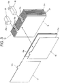
- Figs. 1 to 3 show a lead-acid storage battery according to the embodiment of the invention.
- the lead-acid storage battery is a valve regulated lead-acid storage battery mounted into a vehicle and has a structure in which positive electrode plates 17 and negative electrode plates 18 are layered with separators 21 interposed therebetween inside a container 10 and known electrolyte solution (H 2 SO 4 ) (not shown) is sealed in.
- H 2 SO 4 known electrolyte solution
- the container 10 has an open-topped rectangular parallelepiped shape.
- An upper end opening 10a of the container 10 is sealed with a lid body 11.
- partitions 12 are disposed parallel at equal intervals along a layered direction of the plates 17 and 18 (a direction orthogonal to a paper surface of Fig. 1 ).
- five partitions 12 are formed to divide the inside of the container 10 into six cells 13 for respectively housing elements 16.
- Ribs 14 protruding from a lower face of the container 10 and extending in the layered direction are provided in each of the cells 13.
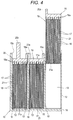
- a narrow portion 15 having a smaller dimension in a width direction orthogonal to the layered direction is formed. Specifically, an inside dimension Sb1 of the narrow portion 15 is smaller than an inside dimension Sb2 of a portion on a side of the upper end opening 10a above the narrow portion 15.
- Each of the elements 16 includes the positive electrode plates 17 and the negative electrode plates 18 which are alternately layered with the separators 21 interposed therebetween and are disposed in the cell 13. Both the plates 17 and 18 are rectangular thin plates having substantially the same dimensions and widths Hp smaller than the inside dimension Sb1 of the narrow portion 15 of the container 10.
- the positive electrode plate 17 is formed by filling a grid made of Pb-Ca alloy with a positive active material mainly made of PbO 2 .
- the negative electrode plate 18 is formed by filling a grid made of Pb-Ca alloy with a negative active material mainly made of Pb.
- a cast grid As each of the grids, a cast grid, an expanded grid formed by slitting and expanding the sheet to form meshes, or a punched grid formed by punching a sheet is used.
- the seven positive electrode plates 17 and the eight negative electrode plates 18 are layered so that the negative electrode plates 18 are positioned at opposite ends.
- Tab-shaped portions 17a and 18a protruding upward are respectively formed at upper end edges of both the plates 17 and 18.
- the tab-shaped portions 17a of the respective positive electrode plates 17 are connected by a positive electrode strap 19 and tab-shaped portions 18a of the respective negative electrode plates 18 are connected by a negative electrode strap 20.
- the positive electrode strap 19 and the negative electrode strap 20 are connected to the respective tab-shaped portions 17a and 18a by a COS (Cast On Strap) method.
- COS Chip On Strap
- connecting portions 19a and 20a for connecting the cells 13, 13 adjacent to each other are formed.
- the connecting portion 19a of the positive electrode strap 19 is connected to the connecting portion 20a of the negative electrode strap 20 of the element 16 disposed in the adjacent cell 13.
- the 12V lead-acid storage battery in which six 2V elements 16 are connected in series is formed.
- a positive electrode terminal 19b passing through the lid body 11 to be exposed to the outside is formed instead of the connecting portion 19a.
- a negative electrode terminal 20b passing through the lid body 11 to be exposed to the outside is formed instead of the connecting portion 20a.
- external terminals (not shown) are connected to the respective terminals 19b and 20b.
- the separator 21 is formed by a fiber mat (e.g., AGM (absorbent glass mat) which has a function of retaining the electrolyte solution and which can be deformed elastically.
- AGM absorbent glass mat
- Each of the separators 21 in the embodiment is of a leaf type which wraps opposite faces of the positive electrode plate 17 in a U shape and is disposed so that a bent portion 21a is positioned on a bottom side of the container 10.
- the separator 21 is wound from one face side of the positive electrode plate 17 and folded back at a lower end edge to extend to the other face side. An upper end of the separator 21 protrudes farther upward than the plates 17 and 18.
- the separator 21 has a uniform width throughout itself before inserted into the container 10 and the width Hs of the separator 21 is greater than or equal to the inside dimension Sb1 of the narrow portion 15 and smaller than or equal to the outside dimension Sb3 of the container 10 above the narrow portion 15.
- the width Hs of the separator 21 in the embodiment is slightly greater than the inside dimension Sb2 above the narrow portion 15 and smaller than the outside dimension Sb3 so that the separator 21 comes in contact with inner faces of a portion of the container 10 adjacent to and above the narrow portion 15.
- the separator 21 formed in this manner has the width Hs greater than the widths Hp of the adjacent plates 17 and 18 and serves as a separating wall for separating the plates 17 and 18 adjacent to each other in the cell 13 of the container 10.
- the width Hs of the separator 21 is preferably 158 mm which is greater than the plates 17 and 18 at least by 5 mm on each side (about 106%).
- the width Hs of the separator 21 is preferably in a range of 105% to 110% of the widths Hp of the plates 17 and 18.
- width Hs is smaller than 105% of the widths Hp, it is difficult to prevent a short circuit caused by elongation of the positive electrode plate 17 or the negative electrode plate 18. If the width Hs is greater than 110% of the widths Hp, workability in housing the separator 21 into the container 10 is reduced. A thickness of the element 16 before housed into the container 10 is greater than an inside dimension of each of the cells 13 in the layered direction.
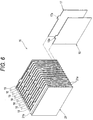
- the positive electrode plate 17 is wrapped in the U-shaped separator 21 and the negative electrode plate 18 is positioned on the outside as shown in Fig. 3 . Then, while pressing the plates 17 and 18, which are alternately layered with the separators 21 interposed therebetween, from opposite sides, the straps 19 and 20 are connected by the COS method to the plates 17 and 18. Then, as shown in Fig. 4 , the pressed element 16 is inserted into each of the divided cells 13.
- the positive electrode strap 19 and a negative electrode strap 20 of the adjacent cells 13 are connected and then the electrolyte solution is filled into the container 10 and the separators 21 are impregnated with the electrolyte solution. Finally, the lid body 11 is disposed at an upper portion of the container 10 to seal the inside of the container 10.
- the separators 21 are deformed and compressed in the width direction on opposite sides of the respective plates 17 and 18 in the narrow portion 15 in the assembled state.
- the separators 21 fill clearances between the respective plates 17 and 18 and the container 10 and it is possible to position the positive electrode plates 17 and the negative electrode plates 18 in the cells 13 with large retaining force. Therefore, it is possible to suppress falling off of the active materials due to vibrations and the like.
- the narrow portion 15 is formed at the end portion of the container 10 on the opposite side from the opening 10a, it is easy to insert the elements 16 into the container 10, which improves workability and suppresses damage to the separators 21 due to rubbing of the separators 21 during insertion. Furthermore, it is possible to enhance stability of the respective plates 17 and 18 and the separators 21 in disposed states.
- the separators 21 serve as the separating walls for separating the positive electrode plates 17 and the negative electrode plates 18 from each other in the container 10. Therefore, the short circuit between the plates 17 and 18 due to elongation of the positive electrode plate 17 or the negative electrode plate 18 can be reliably suppressed and the short circuit between the plates 17 and 18 due to the active materials which have fallen off from the plates 17 and 18 can be suppressed.
- the separators 21 are of the leaf types for wrapping the fewer positive electrode plates 17 in the U shapes, it is possible to reduce the necessary number of separators 21 to thereby reduce cost of the lead-acid storage battery. Moreover, because bent portions 21a of the separators 21 are disposed on a bottom side of the container 10, it is possible to suppress damage to the separators 21 due to rubbing of the separators 21 in inserting the elements 16 into the container 10 and it is possible to further improve workability. Furthermore, because the fallen active materials are caught in the bent portions 21a, it is difficult for the fallen active materials to go around the U-shaped separators 21 to move in the container 10 and it is possible to further suppress the short circuit between the plates 17 and 18.
- the lead-acid storage battery in the invention is not limited to the structure in the embodiment and can be changed in various ways.
- the widths Hs of the separators 21 are greater than the inside dimension Sb2 of the container 10 above the narrow portion 15 in the embodiment, the widths Hs may be equal to or smaller than the inside dimension Sb2.
- the separators 21 are elastically deformable glass mats, the separators 21 have higher elasticity than separators made of polyethylene, for example, and can fix the positive electrode plates 17 and the negative electrode plates 18 to the container 10 with larger retaining force. Therefore, it is possible to further suppress falling off of the active materials due to vibrations and the like.
- the separators 21 formed by glass mats are more liable to get damaged while rubbing against the container 10 when the elements 16 are housed into the container 10 as compared with the separators made of polyethylene, for example, the widths of the separators 21 are smaller than the inside dimension Sb2 in the width direction of the portion of the container 10 above the narrow portion 15 and therefore it is possible to suppress the damage due to rubbing against the container 10.
- the separator 21 before inserted into the container 10 has the uniform width throughout itself in the above embodiment, they need not be uniform, if the above-described predetermined width is obtained after the insertion into the container 10.
- the separator 21 may have a width of 154 mm, which is equal to the inside dimension Sb1 of the narrow portion 15, at a portion in contact with the narrow portion 15 of the container 10 and a width of 158 mm at the other portion.
- the positive electrode plate 17 is wrapped in the separator 21 in the above embodiment, the negative electrode plate 18 may be wrapped in the separator 21.
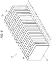
- the separator 21 is not limited to the leaf-type separator 21 for wrapping the single plate 17 or 18 in the U shape and may be a rectangular sheet disposed on each face of the plates 17 and 18 as shown in Fig. 5 .
- the separator 21 may be in a wave shape in which all the plates 17 and 18 can be taken in and wrapped in a zig-zag fashion.
- lower portions of the separator 21 are bent portions 21a and upper portions are folded-back portions 21b.
- the respective plates 17 and 18 are disposed between the folded-back portions 21b, 21b and positioned in the bent portions 21a. In this way, the short circuit due to the elongation of the positive electrode plate 17 or the negative electrode plate 18 can be suppressed and the short circuit due to the fallen active materials can be further reliably suppressed.
- the separator 21 may be formed into a sack shape with only its upper end open by joining lower end edges and edges on both sides in a lateral direction by sewing or the like. In this way, the short circuit due to elongation of the positive electrode plate 17 or the negative electrode plate 18 and the short circuit due to the fallen active materials can be further reliably suppressed.
- valve-regulated lead-acid storage battery has been described in the above embodiment, the invention can be applied to lead-acid storage batteries in which separators 21 are disposed between positive electrode plates 17 and negative electrode plates 18 and similar operation and effects can be obtained.
- the separators are compressed in the narrow portion to fill the clearances between the respective plates and the container and therefore the positive electrode plates and the negative electrode plates can be fixed to the container with large retaining force in the lead-acid storage battery.
- the separators serve as separating walls for separating the positive electrode plates and the negative electrode plates from each other in the container. Therefore, the short circuit between the plates due to elongation of the positive electrode plate or the negative electrode plate can be suppressed and the short circuit between the plates due to the active materials which have fallen off from the plates can be suppressed.
Landscapes
- Chemical & Material Sciences (AREA)
- Chemical Kinetics & Catalysis (AREA)
- Electrochemistry (AREA)
- General Chemical & Material Sciences (AREA)
- Engineering & Computer Science (AREA)
- Manufacturing & Machinery (AREA)
- Ceramic Engineering (AREA)
- Inorganic Chemistry (AREA)
- Secondary Cells (AREA)
- Cell Separators (AREA)
- Sealing Battery Cases Or Jackets (AREA)
Claims (15)
- Blei-Säure-Speicherbatterie, die ein Behältnis (10) umfasst, in dem ein Element (16) aufgenommen ist, das durch wechselweises Schichten einer positiven Elektrodenplatte (17) und einer negativen Elektrodenplatte (18) gebildet wird, wobei eine verformbarer Trenneinrichtung (21) dazwischen angeordnet ist,
wobei das Behältnis (10) eine Öffnung (10a) auf einer Seite und einen schmalen Abschnitt (15), der an einem Endabschnitt des Behältnisses (10) auf einer der Öffnung (10a) gegenüberliegenden Seite ausgebildet ist, umfasst, wobei der schmale Abschnitt (15) eine kleine Innenabmessung in einer Breitenrichtung aufweist, die eine Schichtungsrichtung des Elements (16) schneidet, und
wobei eine Breite einer jeden der Platten (17, 18) kleiner ist als die Innenabmessung in der Breitenrichtung des schmalen Abschnitts (15) des Behältnisses (10), und eine Breite der Trenneinrichtung (21) mindestens so groß ist wie die Innenabmessung des schmalen Abschnitts (15) des Behältnisses (10),
dadurch gekennzeichnet, dass
die Trenneinrichtung (21) in der Breitenrichtung in dem schmalen Abschnitt (15) zusammengedrückt ist. - Blei-Säure-Speicherbatterie nach Anspruch 1,
wobei die Trenneinrichtung (21) eine elastisch verformbare Fasermatte ist. - Blei-Säure-Speicherbatterie nach Anspruch 1 oder 2, wobei die Trenneinrichtung (21) eine solche Breite hat, dass die Trenneinrichtung (21) in Kontakt mit Innenflächen eines Abschnitts des Behältnisses (10) neben dem schmalen Abschnitt (15) kommt.
- Blei-Säure-Speicherbatterie nach Anspruch 1 oder 2,
wobei die Breite der Trenneinrichtung (21) mindestens so groß ist wie die Innenabmessung des schmalen Abschnitts (15) des Behältnisses (10) und kleiner als eine Innenabmessung in der Breitenrichtung des Abschnitts des Behältnisses (10) neben dem schmalen Abschnitt (15) ist. - Blei-Säure-Speicherbatterie nach einem der Ansprüche 1 bis 4, wobei die Trenneinrichtung (21) eine elastisch verformbare Glasmatte ist.
- Blei-Säure-Speicherbatterie nach einem der Ansprüche 1 bis 5,
wobei die Trenneinrichtung (21) so angeordnet ist, dass sie mindestens eine der positiven Elektrodenplatte (17) und der negativen Elektrodenplatte (18) in einer U-Form umhüllt, und
ein U-förmig gebogener Abschnitt der Trenneinrichtung (21) an dem Endabschnitt des Behältnisses (10) auf der der Öffnung (10a) gegenüberliegenden Seite positioniert ist. - Blei-Säure-Speicherbatterie nach einem der Ansprüche 1 bis 6,
wobei die negativen Elektrodenplatten (18) in einer um Eins größeren Zahl vorhanden sind als die positiven Elektrodenplatte (17), und
die Trenneinrichtung (21) so angeordnet ist, dass sie die positive Elektrodenplatte (17) in der U-Form umhüllt. - Blei-Säure-Speicherbatterie nach einem der Ansprüche 1 bis 7,
wobei das Element in einem zusammengedrückten Zustand in dem Behältnis (10) aufgenommen ist. - Blei-Säure-Speicherbatterie nach einem der Ansprüche 1 bis 8,
wobei die Trenneinrichtung (21) so angeordnet ist, dass sie die negative Elektrodenplatte (18) in einer U-Form umhüllt. - Blei-Säure-Speicherbatterie nach einem der Ansprüche 1 bis 5 und 8,
wobei die Trenneinrichtung (21) eine rechteckige Folie ist, die auf jeder Fläche der positiven Elektrodenplatte (17) und der negativen Elektrodenplatte (18) angeordnet ist. - Blei-Säure-Speicherbatterie nach einem der Ansprüche 1 bis 5 und 8,
wobei die Trenneinrichtung (21) eine Wellenform hat, wobei untere Abschnitte der Trenneinrichtung (21) gebogene Abschnitte sind und ein oberer Abschnitt der Trenneinrichtung (21) ein zurückgefalteter Abschnitt ist, und die positive Elektrodenplatte (17) und die negative Elektrodenplatte (18) in den gebogenen Abschnitten positioniert sind. - Blei-Säure-Speicherbatterie nach einem der Ansprüche 1 bis 11,
wobei die Trenneinrichtung (21) zu einer Sackform gebildet ist, wobei ein oberes Ende offen ist, indem Ränder am unteren Ende und Ränder auf beiden Seiten in einer seitlichen Richtung miteinander verbunden werden. - Blei-Säure-Speicherbatterie nach einem der Ansprüche 1 bis 12,
wobei die Breite der Trenneinrichtung (21) um mindestens 5 mm auf jeder Seite größer ist als die positive Elektrodenplatte (17) oder die negative Elektrodenplatte (18). - Blei-Säure-Speicherbatterie nach einem der Ansprüche 1 bis 13,
wobei die Breite der Trenneinrichtung (21) in einem Bereich von 105 % bis 110 % einer Breite mindestens einer der positiven Elektrodenplatte (17) und der negativen Elektrodenplatte (18) liegt. - Blei-Säure-Speicherbatterie nach einem der Ansprüche 1 bis 14, wobei die Blei-Säure-Speicherbatterie eine ventilgeregelte Blei-Säure-Speicherbatterie ist.
Applications Claiming Priority (1)
| Application Number | Priority Date | Filing Date | Title |
|---|---|---|---|
| JP2013121121A JP2014238983A (ja) | 2013-06-07 | 2013-06-07 | 鉛蓄電池 |
Publications (3)
| Publication Number | Publication Date |
|---|---|
| EP2811546A2 EP2811546A2 (de) | 2014-12-10 |
| EP2811546A3 EP2811546A3 (de) | 2015-01-14 |
| EP2811546B1 true EP2811546B1 (de) | 2016-03-23 |
Family
ID=50884781
Family Applications (1)
| Application Number | Title | Priority Date | Filing Date |
|---|---|---|---|
| EP14171546.6A Active EP2811546B1 (de) | 2013-06-07 | 2014-06-06 | Blei-Säureakkumulator |
Country Status (3)
| Country | Link |
|---|---|
| US (1) | US10050239B2 (de) |
| EP (1) | EP2811546B1 (de) |
| JP (1) | JP2014238983A (de) |
Families Citing this family (4)
| Publication number | Priority date | Publication date | Assignee | Title |
|---|---|---|---|---|
| KR101823584B1 (ko) * | 2015-03-04 | 2018-01-30 | 주식회사 엘지화학 | 전지 팩 |
| WO2019087682A1 (ja) * | 2017-10-31 | 2019-05-09 | 株式会社Gsユアサ | 鉛蓄電池 |
| JP6956258B2 (ja) * | 2018-03-28 | 2021-11-02 | 本田技研工業株式会社 | 固体電池モジュール |
| CN114725531A (zh) * | 2022-04-08 | 2022-07-08 | 超威电源集团有限公司 | 一种阀控式铅酸蓄电池极群及其制作方法 |
Family Cites Families (18)
| Publication number | Priority date | Publication date | Assignee | Title |
|---|---|---|---|---|
| JPS523118A (en) * | 1975-06-24 | 1977-01-11 | Yuasa Battery Co Ltd | Separator for lead storage battery |
| JPS6064577A (ja) | 1983-09-19 | 1985-04-13 | Fujitsu Ltd | ファクシミリ装置 |
| JPS6064577U (ja) * | 1983-10-08 | 1985-05-08 | 株式会社ユアサコーポレーション | 密閉形鉛蓄電池 |
| JPS60207262A (ja) * | 1984-03-30 | 1985-10-18 | Shin Kobe Electric Mach Co Ltd | 密閉形鉛蓄電池 |
| US4652505A (en) * | 1984-03-29 | 1987-03-24 | Shin-Kobe Machinery Co., Ltd. | Sealed lead storage battery |
| AU570352B2 (en) | 1985-01-17 | 1988-03-10 | Furukawa Denchi Kabushiki Kaisha | Reduced height electrodes in storage battery |
| JPH0239456U (de) * | 1988-09-07 | 1990-03-16 | ||
| JP3384070B2 (ja) | 1993-12-24 | 2003-03-10 | 新神戸電機株式会社 | 密閉形鉛蓄電池 |
| JPH08264201A (ja) * | 1995-03-24 | 1996-10-11 | Japan Storage Battery Co Ltd | 密閉型鉛蓄電池 |
| JPH09171832A (ja) | 1995-12-20 | 1997-06-30 | Shin Kobe Electric Mach Co Ltd | 密閉形鉛蓄電池及びその製造方法 |
| JP3374665B2 (ja) * | 1996-07-23 | 2003-02-10 | 松下電器産業株式会社 | 密閉型鉛蓄電池 |
| JPH11111242A (ja) | 1997-10-08 | 1999-04-23 | Shin Kobe Electric Mach Co Ltd | 鉛蓄電池 |
| JP2004311357A (ja) | 2003-04-10 | 2004-11-04 | Japan Storage Battery Co Ltd | 鉛蓄電池 |
| US20050019652A1 (en) * | 2003-07-21 | 2005-01-27 | Fauteux Denis G. | Electrode assembly and method of manufacturing same |
| JP2009252435A (ja) | 2008-04-03 | 2009-10-29 | Panasonic Corp | 鉛蓄電池 |
| JP4359857B1 (ja) | 2008-05-13 | 2009-11-11 | トヨタ自動車株式会社 | 角型電池 |
| WO2011029035A2 (en) * | 2009-09-04 | 2011-03-10 | Johnson Controls Technology Company | Secondary battery with improved acid destratification |
| EP3467898B1 (de) | 2010-10-15 | 2020-07-15 | Clarios Germany GmbH & Co. KGaA | Akkumulator mit einem wandelement und wandelement dafür |
-
2013
- 2013-06-07 JP JP2013121121A patent/JP2014238983A/ja active Pending
-
2014
- 2014-06-03 US US14/294,653 patent/US10050239B2/en active Active
- 2014-06-06 EP EP14171546.6A patent/EP2811546B1/de active Active
Also Published As
| Publication number | Publication date |
|---|---|
| EP2811546A3 (de) | 2015-01-14 |
| US10050239B2 (en) | 2018-08-14 |
| US20140363724A1 (en) | 2014-12-11 |
| JP2014238983A (ja) | 2014-12-18 |
| EP2811546A2 (de) | 2014-12-10 |
Similar Documents
| Publication | Publication Date | Title |
|---|---|---|
| EP2811546B1 (de) | Blei-Säureakkumulator | |
| US9397364B2 (en) | Electric storage device and electric storage apparatus | |
| US9379363B2 (en) | Cylindrical battery | |
| US10468711B2 (en) | Electrode plate, layered electrode group, and battery | |
| CN109155380B (zh) | 包括罩盖组件的蓄电池模块 | |
| JP6638795B2 (ja) | 鉛蓄電池及びその製造方法 | |
| US9722215B2 (en) | Cylindrical battery | |
| JP2015185470A (ja) | 蓄電素子 | |
| WO2021192545A1 (ja) | 電池モジュール | |
| CN104871339B (zh) | 电池模块 | |
| JP2007018833A (ja) | 蓄電池の製造方法 | |
| KR102317274B1 (ko) | 배터리 모듈 및 이를 포함하는 배터리 팩 | |
| JP2017117633A (ja) | 組電池の製造方法 | |
| US2757222A (en) | Electric storage batteries | |
| JP7040881B2 (ja) | 鉛蓄電池 | |
| JP7241054B2 (ja) | 二次電池 | |
| JP2015053220A (ja) | 蓄電装置及び蓄電装置の製造方法 | |
| JP7557527B2 (ja) | 電池モジュール | |
| JP2003092099A (ja) | 鉛蓄電池 | |
| KR20240123237A (ko) | 축전 디바이스 및 축전 디바이스의 제조 방법 | |
| JP2019102364A (ja) | 鉛蓄電池 | |
| JP2024111477A (ja) | 蓄電デバイス及び蓄電デバイスの製造方法 | |
| CN111082121A (zh) | 蓄电单元及蓄电单元的制造方法 | |
| JP2003243023A (ja) | 鉛蓄電池 |
Legal Events
| Date | Code | Title | Description |
|---|---|---|---|
| PUAI | Public reference made under article 153(3) epc to a published international application that has entered the european phase |
Free format text: ORIGINAL CODE: 0009012 |
|
| 17P | Request for examination filed |
Effective date: 20140606 |
|
| AK | Designated contracting states |
Kind code of ref document: A2 Designated state(s): AL AT BE BG CH CY CZ DE DK EE ES FI FR GB GR HR HU IE IS IT LI LT LU LV MC MK MT NL NO PL PT RO RS SE SI SK SM TR |
|
| AX | Request for extension of the european patent |
Extension state: BA ME |
|
| PUAL | Search report despatched |
Free format text: ORIGINAL CODE: 0009013 |
|
| AK | Designated contracting states |
Kind code of ref document: A3 Designated state(s): AL AT BE BG CH CY CZ DE DK EE ES FI FR GB GR HR HU IE IS IT LI LT LU LV MC MK MT NL NO PL PT RO RS SE SI SK SM TR |
|
| AX | Request for extension of the european patent |
Extension state: BA ME |
|
| RIC1 | Information provided on ipc code assigned before grant |
Ipc: H01M 2/10 20060101ALI20141210BHEP Ipc: H01M 2/20 20060101AFI20141210BHEP Ipc: H01M 2/02 20060101ALI20141210BHEP |
|
| R17P | Request for examination filed (corrected) |
Effective date: 20150713 |
|
| RBV | Designated contracting states (corrected) |
Designated state(s): AL AT BE BG CH CY CZ DE DK EE ES FI FR GB GR HR HU IE IS IT LI LT LU LV MC MK MT NL NO PL PT RO RS SE SI SK SM TR |
|
| GRAP | Despatch of communication of intention to grant a patent |
Free format text: ORIGINAL CODE: EPIDOSNIGR1 |
|
| RIC1 | Information provided on ipc code assigned before grant |
Ipc: H01M 2/10 20060101ALI20150820BHEP Ipc: H01M 2/02 20060101ALI20150820BHEP Ipc: H01M 2/20 20060101AFI20150820BHEP |
|
| INTG | Intention to grant announced |
Effective date: 20150924 |
|
| GRAS | Grant fee paid |
Free format text: ORIGINAL CODE: EPIDOSNIGR3 |
|
| GRAA | (expected) grant |
Free format text: ORIGINAL CODE: 0009210 |
|
| AK | Designated contracting states |
Kind code of ref document: B1 Designated state(s): AL AT BE BG CH CY CZ DE DK EE ES FI FR GB GR HR HU IE IS IT LI LT LU LV MC MK MT NL NO PL PT RO RS SE SI SK SM TR |
|
| REG | Reference to a national code |
Ref country code: GB Ref legal event code: FG4D |
|
| REG | Reference to a national code |
Ref country code: CH Ref legal event code: EP |
|
| REG | Reference to a national code |
Ref country code: AT Ref legal event code: REF Ref document number: 783930 Country of ref document: AT Kind code of ref document: T Effective date: 20160415 |
|
| REG | Reference to a national code |
Ref country code: IE Ref legal event code: FG4D |
|
| REG | Reference to a national code |
Ref country code: DE Ref legal event code: R096 Ref document number: 602014001177 Country of ref document: DE |
|
| REG | Reference to a national code |
Ref country code: LT Ref legal event code: MG4D |
|
| REG | Reference to a national code |
Ref country code: NL Ref legal event code: MP Effective date: 20160323 |
|
| PG25 | Lapsed in a contracting state [announced via postgrant information from national office to epo] |
Ref country code: HR Free format text: LAPSE BECAUSE OF FAILURE TO SUBMIT A TRANSLATION OF THE DESCRIPTION OR TO PAY THE FEE WITHIN THE PRESCRIBED TIME-LIMIT Effective date: 20160323 Ref country code: GR Free format text: LAPSE BECAUSE OF FAILURE TO SUBMIT A TRANSLATION OF THE DESCRIPTION OR TO PAY THE FEE WITHIN THE PRESCRIBED TIME-LIMIT Effective date: 20160624 Ref country code: NO Free format text: LAPSE BECAUSE OF FAILURE TO SUBMIT A TRANSLATION OF THE DESCRIPTION OR TO PAY THE FEE WITHIN THE PRESCRIBED TIME-LIMIT Effective date: 20160623 Ref country code: FI Free format text: LAPSE BECAUSE OF FAILURE TO SUBMIT A TRANSLATION OF THE DESCRIPTION OR TO PAY THE FEE WITHIN THE PRESCRIBED TIME-LIMIT Effective date: 20160323 |
|
| REG | Reference to a national code |
Ref country code: AT Ref legal event code: MK05 Ref document number: 783930 Country of ref document: AT Kind code of ref document: T Effective date: 20160323 |
|
| PG25 | Lapsed in a contracting state [announced via postgrant information from national office to epo] |
Ref country code: LV Free format text: LAPSE BECAUSE OF FAILURE TO SUBMIT A TRANSLATION OF THE DESCRIPTION OR TO PAY THE FEE WITHIN THE PRESCRIBED TIME-LIMIT Effective date: 20160323 Ref country code: RS Free format text: LAPSE BECAUSE OF FAILURE TO SUBMIT A TRANSLATION OF THE DESCRIPTION OR TO PAY THE FEE WITHIN THE PRESCRIBED TIME-LIMIT Effective date: 20160323 Ref country code: LT Free format text: LAPSE BECAUSE OF FAILURE TO SUBMIT A TRANSLATION OF THE DESCRIPTION OR TO PAY THE FEE WITHIN THE PRESCRIBED TIME-LIMIT Effective date: 20160323 Ref country code: NL Free format text: LAPSE BECAUSE OF FAILURE TO SUBMIT A TRANSLATION OF THE DESCRIPTION OR TO PAY THE FEE WITHIN THE PRESCRIBED TIME-LIMIT Effective date: 20160323 Ref country code: SE Free format text: LAPSE BECAUSE OF FAILURE TO SUBMIT A TRANSLATION OF THE DESCRIPTION OR TO PAY THE FEE WITHIN THE PRESCRIBED TIME-LIMIT Effective date: 20160323 |
|
| PG25 | Lapsed in a contracting state [announced via postgrant information from national office to epo] |
Ref country code: PL Free format text: LAPSE BECAUSE OF FAILURE TO SUBMIT A TRANSLATION OF THE DESCRIPTION OR TO PAY THE FEE WITHIN THE PRESCRIBED TIME-LIMIT Effective date: 20160323 Ref country code: EE Free format text: LAPSE BECAUSE OF FAILURE TO SUBMIT A TRANSLATION OF THE DESCRIPTION OR TO PAY THE FEE WITHIN THE PRESCRIBED TIME-LIMIT Effective date: 20160323 Ref country code: IS Free format text: LAPSE BECAUSE OF FAILURE TO SUBMIT A TRANSLATION OF THE DESCRIPTION OR TO PAY THE FEE WITHIN THE PRESCRIBED TIME-LIMIT Effective date: 20160723 |
|
| PG25 | Lapsed in a contracting state [announced via postgrant information from national office to epo] |
Ref country code: SM Free format text: LAPSE BECAUSE OF FAILURE TO SUBMIT A TRANSLATION OF THE DESCRIPTION OR TO PAY THE FEE WITHIN THE PRESCRIBED TIME-LIMIT Effective date: 20160323 Ref country code: AT Free format text: LAPSE BECAUSE OF FAILURE TO SUBMIT A TRANSLATION OF THE DESCRIPTION OR TO PAY THE FEE WITHIN THE PRESCRIBED TIME-LIMIT Effective date: 20160323 Ref country code: RO Free format text: LAPSE BECAUSE OF FAILURE TO SUBMIT A TRANSLATION OF THE DESCRIPTION OR TO PAY THE FEE WITHIN THE PRESCRIBED TIME-LIMIT Effective date: 20160323 Ref country code: SK Free format text: LAPSE BECAUSE OF FAILURE TO SUBMIT A TRANSLATION OF THE DESCRIPTION OR TO PAY THE FEE WITHIN THE PRESCRIBED TIME-LIMIT Effective date: 20160323 Ref country code: CZ Free format text: LAPSE BECAUSE OF FAILURE TO SUBMIT A TRANSLATION OF THE DESCRIPTION OR TO PAY THE FEE WITHIN THE PRESCRIBED TIME-LIMIT Effective date: 20160323 Ref country code: ES Free format text: LAPSE BECAUSE OF FAILURE TO SUBMIT A TRANSLATION OF THE DESCRIPTION OR TO PAY THE FEE WITHIN THE PRESCRIBED TIME-LIMIT Effective date: 20160323 Ref country code: PT Free format text: LAPSE BECAUSE OF FAILURE TO SUBMIT A TRANSLATION OF THE DESCRIPTION OR TO PAY THE FEE WITHIN THE PRESCRIBED TIME-LIMIT Effective date: 20160725 |
|
| PG25 | Lapsed in a contracting state [announced via postgrant information from national office to epo] |
Ref country code: IT Free format text: LAPSE BECAUSE OF FAILURE TO SUBMIT A TRANSLATION OF THE DESCRIPTION OR TO PAY THE FEE WITHIN THE PRESCRIBED TIME-LIMIT Effective date: 20160323 Ref country code: BE Free format text: LAPSE BECAUSE OF FAILURE TO SUBMIT A TRANSLATION OF THE DESCRIPTION OR TO PAY THE FEE WITHIN THE PRESCRIBED TIME-LIMIT Effective date: 20160323 |
|
| REG | Reference to a national code |
Ref country code: DE Ref legal event code: R097 Ref document number: 602014001177 Country of ref document: DE |
|
| PLBE | No opposition filed within time limit |
Free format text: ORIGINAL CODE: 0009261 |
|
| STAA | Information on the status of an ep patent application or granted ep patent |
Free format text: STATUS: NO OPPOSITION FILED WITHIN TIME LIMIT |
|
| PG25 | Lapsed in a contracting state [announced via postgrant information from national office to epo] |
Ref country code: DK Free format text: LAPSE BECAUSE OF FAILURE TO SUBMIT A TRANSLATION OF THE DESCRIPTION OR TO PAY THE FEE WITHIN THE PRESCRIBED TIME-LIMIT Effective date: 20160323 Ref country code: MC Free format text: LAPSE BECAUSE OF FAILURE TO SUBMIT A TRANSLATION OF THE DESCRIPTION OR TO PAY THE FEE WITHIN THE PRESCRIBED TIME-LIMIT Effective date: 20160323 |
|
| PG25 | Lapsed in a contracting state [announced via postgrant information from national office to epo] |
Ref country code: BG Free format text: LAPSE BECAUSE OF FAILURE TO SUBMIT A TRANSLATION OF THE DESCRIPTION OR TO PAY THE FEE WITHIN THE PRESCRIBED TIME-LIMIT Effective date: 20160623 |
|
| 26N | No opposition filed |
Effective date: 20170102 |
|
| REG | Reference to a national code |
Ref country code: IE Ref legal event code: MM4A |
|
| REG | Reference to a national code |
Ref country code: FR Ref legal event code: ST Effective date: 20170228 |
|
| PG25 | Lapsed in a contracting state [announced via postgrant information from national office to epo] |
Ref country code: FR Free format text: LAPSE BECAUSE OF NON-PAYMENT OF DUE FEES Effective date: 20160630 |
|
| PG25 | Lapsed in a contracting state [announced via postgrant information from national office to epo] |
Ref country code: SI Free format text: LAPSE BECAUSE OF FAILURE TO SUBMIT A TRANSLATION OF THE DESCRIPTION OR TO PAY THE FEE WITHIN THE PRESCRIBED TIME-LIMIT Effective date: 20160323 Ref country code: IE Free format text: LAPSE BECAUSE OF NON-PAYMENT OF DUE FEES Effective date: 20160606 |
|
| REG | Reference to a national code |
Ref country code: CH Ref legal event code: PL |
|
| PG25 | Lapsed in a contracting state [announced via postgrant information from national office to epo] |
Ref country code: CH Free format text: LAPSE BECAUSE OF NON-PAYMENT OF DUE FEES Effective date: 20170630 Ref country code: LI Free format text: LAPSE BECAUSE OF NON-PAYMENT OF DUE FEES Effective date: 20170630 |
|
| PG25 | Lapsed in a contracting state [announced via postgrant information from national office to epo] |
Ref country code: HU Free format text: LAPSE BECAUSE OF FAILURE TO SUBMIT A TRANSLATION OF THE DESCRIPTION OR TO PAY THE FEE WITHIN THE PRESCRIBED TIME-LIMIT; INVALID AB INITIO Effective date: 20140606 |
|
| PG25 | Lapsed in a contracting state [announced via postgrant information from national office to epo] |
Ref country code: MT Free format text: LAPSE BECAUSE OF NON-PAYMENT OF DUE FEES Effective date: 20160630 Ref country code: MK Free format text: LAPSE BECAUSE OF FAILURE TO SUBMIT A TRANSLATION OF THE DESCRIPTION OR TO PAY THE FEE WITHIN THE PRESCRIBED TIME-LIMIT Effective date: 20160323 Ref country code: CY Free format text: LAPSE BECAUSE OF FAILURE TO SUBMIT A TRANSLATION OF THE DESCRIPTION OR TO PAY THE FEE WITHIN THE PRESCRIBED TIME-LIMIT Effective date: 20160323 Ref country code: LU Free format text: LAPSE BECAUSE OF NON-PAYMENT OF DUE FEES Effective date: 20160606 |
|
| PG25 | Lapsed in a contracting state [announced via postgrant information from national office to epo] |
Ref country code: TR Free format text: LAPSE BECAUSE OF FAILURE TO SUBMIT A TRANSLATION OF THE DESCRIPTION OR TO PAY THE FEE WITHIN THE PRESCRIBED TIME-LIMIT Effective date: 20160323 Ref country code: AL Free format text: LAPSE BECAUSE OF FAILURE TO SUBMIT A TRANSLATION OF THE DESCRIPTION OR TO PAY THE FEE WITHIN THE PRESCRIBED TIME-LIMIT Effective date: 20160323 |
|
| GBPC | Gb: european patent ceased through non-payment of renewal fee |
Effective date: 20180606 |
|
| PG25 | Lapsed in a contracting state [announced via postgrant information from national office to epo] |
Ref country code: GB Free format text: LAPSE BECAUSE OF NON-PAYMENT OF DUE FEES Effective date: 20180606 |
|
| REG | Reference to a national code |
Ref country code: DE Ref legal event code: R079 Ref document number: 602014001177 Country of ref document: DE Free format text: PREVIOUS MAIN CLASS: H01M0002200000 Ipc: H01M0050500000 |
|
| P01 | Opt-out of the competence of the unified patent court (upc) registered |
Effective date: 20230522 |
|
| PGFP | Annual fee paid to national office [announced via postgrant information from national office to epo] |
Ref country code: DE Payment date: 20240502 Year of fee payment: 11 |