EP2811141B1 - Latente wärmetauscherabdeckung mit einer kühlleitung - Google Patents
Latente wärmetauscherabdeckung mit einer kühlleitung Download PDFInfo
- Publication number
- EP2811141B1 EP2811141B1 EP13743218.3A EP13743218A EP2811141B1 EP 2811141 B1 EP2811141 B1 EP 2811141B1 EP 13743218 A EP13743218 A EP 13743218A EP 2811141 B1 EP2811141 B1 EP 2811141B1
- Authority
- EP
- European Patent Office
- Prior art keywords
- heat exchanger
- latent heat
- exhaust gas
- cooling line
- cover
- Prior art date
- Legal status (The legal status is an assumption and is not a legal conclusion. Google has not performed a legal analysis and makes no representation as to the accuracy of the status listed.)
- Not-in-force
Links
Images


Classifications
-
- F—MECHANICAL ENGINEERING; LIGHTING; HEATING; WEAPONS; BLASTING
- F02—COMBUSTION ENGINES; HOT-GAS OR COMBUSTION-PRODUCT ENGINE PLANTS
- F02G—HOT GAS OR COMBUSTION-PRODUCT POSITIVE-DISPLACEMENT ENGINE PLANTS; USE OF WASTE HEAT OF COMBUSTION ENGINES; NOT OTHERWISE PROVIDED FOR
- F02G1/00—Hot gas positive-displacement engine plants
- F02G1/04—Hot gas positive-displacement engine plants of closed-cycle type
- F02G1/043—Hot gas positive-displacement engine plants of closed-cycle type the engine being operated by expansion and contraction of a mass of working gas which is heated and cooled in one of a plurality of constantly communicating expansible chambers, e.g. Stirling cycle type engines
- F02G1/053—Component parts or details
- F02G1/055—Heaters or coolers
-
- F—MECHANICAL ENGINEERING; LIGHTING; HEATING; WEAPONS; BLASTING
- F28—HEAT EXCHANGE IN GENERAL
- F28F—DETAILS OF HEAT-EXCHANGE AND HEAT-TRANSFER APPARATUS, OF GENERAL APPLICATION
- F28F9/00—Casings; Header boxes; Auxiliary supports for elements; Auxiliary members within casings
- F28F9/001—Casings in the form of plate-like arrangements; Frames enclosing a heat exchange core
-
- F—MECHANICAL ENGINEERING; LIGHTING; HEATING; WEAPONS; BLASTING
- F02—COMBUSTION ENGINES; HOT-GAS OR COMBUSTION-PRODUCT ENGINE PLANTS
- F02G—HOT GAS OR COMBUSTION-PRODUCT POSITIVE-DISPLACEMENT ENGINE PLANTS; USE OF WASTE HEAT OF COMBUSTION ENGINES; NOT OTHERWISE PROVIDED FOR
- F02G1/00—Hot gas positive-displacement engine plants
- F02G1/04—Hot gas positive-displacement engine plants of closed-cycle type
- F02G1/043—Hot gas positive-displacement engine plants of closed-cycle type the engine being operated by expansion and contraction of a mass of working gas which is heated and cooled in one of a plurality of constantly communicating expansible chambers, e.g. Stirling cycle type engines
-
- F—MECHANICAL ENGINEERING; LIGHTING; HEATING; WEAPONS; BLASTING
- F25—REFRIGERATION OR COOLING; COMBINED HEATING AND REFRIGERATION SYSTEMS; HEAT PUMP SYSTEMS; MANUFACTURE OR STORAGE OF ICE; LIQUEFACTION SOLIDIFICATION OF GASES
- F25B—REFRIGERATION MACHINES, PLANTS OR SYSTEMS; COMBINED HEATING AND REFRIGERATION SYSTEMS; HEAT PUMP SYSTEMS
- F25B29/00—Combined heating and refrigeration systems, e.g. operating alternately or simultaneously
-
- F—MECHANICAL ENGINEERING; LIGHTING; HEATING; WEAPONS; BLASTING
- F28—HEAT EXCHANGE IN GENERAL
- F28D—HEAT-EXCHANGE APPARATUS, NOT PROVIDED FOR IN ANOTHER SUBCLASS, IN WHICH THE HEAT-EXCHANGE MEDIA DO NOT COME INTO DIRECT CONTACT
- F28D21/00—Heat-exchange apparatus not covered by any of the groups F28D1/00 - F28D20/00
- F28D21/0001—Recuperative heat exchangers
- F28D21/0003—Recuperative heat exchangers the heat being recuperated from exhaust gases
- F28D21/001—Recuperative heat exchangers the heat being recuperated from exhaust gases for thermal power plants or industrial processes
-
- F—MECHANICAL ENGINEERING; LIGHTING; HEATING; WEAPONS; BLASTING
- F02—COMBUSTION ENGINES; HOT-GAS OR COMBUSTION-PRODUCT ENGINE PLANTS
- F02G—HOT GAS OR COMBUSTION-PRODUCT POSITIVE-DISPLACEMENT ENGINE PLANTS; USE OF WASTE HEAT OF COMBUSTION ENGINES; NOT OTHERWISE PROVIDED FOR
- F02G2260/00—Recuperating heat from exhaust gases of combustion engines and heat from cooling circuits
-
- F—MECHANICAL ENGINEERING; LIGHTING; HEATING; WEAPONS; BLASTING
- F28—HEAT EXCHANGE IN GENERAL
- F28F—DETAILS OF HEAT-EXCHANGE AND HEAT-TRANSFER APPARATUS, OF GENERAL APPLICATION
- F28F2270/00—Thermal insulation; Thermal decoupling
-
- Y—GENERAL TAGGING OF NEW TECHNOLOGICAL DEVELOPMENTS; GENERAL TAGGING OF CROSS-SECTIONAL TECHNOLOGIES SPANNING OVER SEVERAL SECTIONS OF THE IPC; TECHNICAL SUBJECTS COVERED BY FORMER USPC CROSS-REFERENCE ART COLLECTIONS [XRACs] AND DIGESTS
- Y02—TECHNOLOGIES OR APPLICATIONS FOR MITIGATION OR ADAPTATION AGAINST CLIMATE CHANGE
- Y02P—CLIMATE CHANGE MITIGATION TECHNOLOGIES IN THE PRODUCTION OR PROCESSING OF GOODS
- Y02P80/00—Climate change mitigation technologies for sector-wide applications
- Y02P80/10—Efficient use of energy, e.g. using compressed air or pressurized fluid as energy carrier
- Y02P80/15—On-site combined power, heat or cool generation or distribution, e.g. combined heat and power [CHP] supply
Definitions
- the present invention relates to a latent heat exchanger cover, and more specifically to a latent heat exchanger cover in which a cooling line is provided on one side of the latent heat exchanger cover of an auxiliary boiler that is equipped in a micro combined heat and power system, to prevent transfer from being transferred to exhaust gas that is passed through and emitted out of the latent heat exchanger, thereby minimizing heat loss of fluid flowing into the auxiliary boiler.
- organic rankine cycle is applied when converting middle and low temperature exhaust gas into high quality energy mechanical power.
- Aforesaid organic rankine cycle is a type of power cycle that uses organic heating medium having higher air pressure than water as the moving fluid, and allows mechanical power to be obtained under conditions of low temperature heat sources with relative high heat efficiency.
- known organic rankine cycle consists of a correlation of individual devices such as a circulation pump, a turbine, a condenser, and an evaporator. This creates a closed circulation cycle wherein a working fluid evaporates from the evaporator, after which mechanical power is generated as it expands in the turbine, followed by reliquefication in the condenser, and supplied again to the evaporator by the pump.
- stirling engines are also known, in which each constituting element configuring the power cycle are assembled into a single engine, and gas such as air is used as the moving fluid. Therefore, it provides the benefit of the device being very simple with easy operation.
- stirling engine has greatest thermal efficiency among power cycles. Therefore, the stirling engine has a very simple structure compared to the conventional organic rankine system when converting middle and low temperature thermal energy to power, and also allows conversion of highly efficient energy.
- This document discloses a latent heat exchanger cover provided in a micro combined heat and power system.
- This micro combined heat and power system comprises a stirling engine being heated by an engine burner to produce electricity. Additionally it comprises an auxiliary boiler provided above the stirling engine and being equipped with a sensible heat exchanger and a latent heat exchanger. The boiler and both heat exchangers are intended to produce hot water. Additionally a cooling line is provided, separating hot exhaust gas and cold exhaust gas such that heat exchange between these two exhaust gas flows is prevented.
- Patent Literature 1 Patent Application No. 10-2010-79470
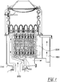
- the emission structure of an exhaust passage in a micro combined heat and power system disclosed in the aforementioned patent literature does not immediately emit the engine exhaust gas, but is instead configured to increase heat efficiency by inducing the engine exhaust gas towards the upper portion of the latent heat exchanger (220), then emitting it after passing it through the latent heat exchanger (220) to the lower portion thereof, thereby recovering high temperature waste heat included in the exhaust gas.
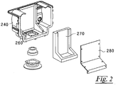
- long term use results in inadequate heat exchange because heat is inducted to the insulator (270) and the sealing member (280).
- the present invention has been made to solve the above-described problem occurring in the prior art, and an object of the present invention is to provide a latent heat exchanger cover with a cooling line, wherein the cooling line through which cooling water can flow is formed between the exhaust gas that has passed through the latent heat exchanger and the communication pipe formed on the lateral side, thereby increasing insulation and minimizing heat loss of the fluid transported to the communication pipe.
- the present invention which aims to solve the above-described problem, is directed to a micro combined heat and power system comprising a stirling engine heated by an engine burner to produce electricity, and an auxiliary boiler installed above the stirling engine and consisting of a sensible heat exchanger and a latent heat exchanger to produce hot water.
- the exhaust gas which heats the stirling engine moves by passing through the communication pipe and the lateral side of the latent heat exchanger, and then undergoes heat exchange while flowing from the upper portion to the lower portion of the latent heat exchanger.
- a cooling line through which cooling water can flow is created on one side of the cover enclosing the latent heat exchanger, in order to prevent heat created in the communication pipe from being transferred to the exhaust gas that has undergone heat exchange by passing through the latent heat exchanger.
- the cooling line is characterized by being integrally formed with the cover.
- FIG. 3 is a mimetic diagram showing emission process of a stirling engine exhaust gas in a micro combined heat and power system equipped with a latent heat exchanger cover with the cooling line according to the present invention
- FIG. 4 is a perspective view showing the auxiliary boiler configured in FIG. 3
- FIG. 5 is a section view showing the engine exhaust passage of FIG. 4
- FIG. 6 is a partially enlarged section view showing the cooling line provided in FIG. 5 .
- the micro combined heat and power system comprises a housing (100), wherein a stirling engine (110) is installed in the housing (100), and an auxiliary boiler (200) is installed above the stirling engine (110).
- the stirling engine (110) is operated by a main boiler (not shown), and an engine burner (120) equipped in the main boiler heats the engine head (not shown) of the stirling engine (110), causing the working fluid sealed within the main boiler to expand and contract via the temperature difference, thereby producing alternating current.
- the auxiliary boiler (200) comprises a sensible heat exchanger (210) and a latent heat exchanger (220), and produces hot water by the high temperature heat exchange provided through a flat plate type burner.
- the hot water produced through this process is used after being stored in a storage tank (300), in which case a cooling water pipe (130) is configured to pass through the stirling engine (110), then through the latent heat exchanger (220) and the sensible heat exchanger (210) in order to cool the stirling engine (110).
- a cooling water pipe (130) is configured to pass through the stirling engine (110), then through the latent heat exchanger (220) and the sensible heat exchanger (210) in order to cool the stirling engine (110).
- the auxiliary boiler (200) has a latent heat exchanger (220) built in the case (230), and a sensible heat exchanger (210) is assembled above the case (230).
- the front portion of the case (230) is partially open, and the open portion is sealed by a cover (240) forming the passage of the engine exhaust gas.
- a hole (not shown) is formed on the underside of the cover (240), and a communication pipe (250) is connected to the hole.
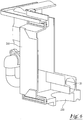
- the communication pipe (250) is interfaced to the engine head of the stirling engine (110) to carry out the function of inducing emission of the exhaust gas that is combusted from the engine burner (120) and then exhausted after heating the stirling engine (110).
- the flange shape of the communication pipe permits easy assembly.
- the latent heat exchange cover with a cooling line of the present invention is provided with a cooling line (10) integrally formed with the latent heat exchanger cover (240) on the lateral side of the communication pipe (250) through which cooling water can flow, such that the communication pipe (250) is interposed between the front surface of the cover (240) and the cooling line (10).
- the cooling line (10) is configured to allow separate cooling water to flow through, but it is preferable to have the cooling line manufactured integrally with the cover (240) in a water jacket shape, as illustrated in FIG. 6 .
- a separate cooling line is formed within the cover (240), in the region in contact with the communication pipe (250), to form a passage inducing the exhaust gas discharged through the upper portion of the communication pipe (250) to the latent heat exchanger (220).
- it acts as an insulator by which high temperature heat of the exhaust gas flowing in to the communication pipe (250) is prevented from being transferred to the exhaust gas already discharged through the latent heat exchanger (220). In this way, heat loss of the exhaust gas passing through the communication pipe (250) is minimized.
- heat loss of the exhaust gas passing through the communication pipe (250) can be prevented at the beginning of the operation of the micro combined heat and power system using an insulator (270) and a sealing member (280) (Refer to FIG. 2 ).
- the insulator (270) and the sealing member (280) are overheated upon long term use, which prevents effective insulation.
Landscapes
- Engineering & Computer Science (AREA)
- Mechanical Engineering (AREA)
- General Engineering & Computer Science (AREA)
- Physics & Mathematics (AREA)
- Thermal Sciences (AREA)
- Chemical & Material Sciences (AREA)
- Combustion & Propulsion (AREA)
- Engine Equipment That Uses Special Cycles (AREA)
- Heat-Pump Type And Storage Water Heaters (AREA)
- Heat-Exchange Devices With Radiators And Conduit Assemblies (AREA)
Claims (2)
- Latent-Wärmetauscher-Gehäuse eines Kraft-WärmeKopplungs-Systems, wobei das Kraft-Wärmekopplungs-System einen Sterlingmotor (110) aufweist, welcher von einem Motorbrenner (120) erwärmt wird, um elektrischen Strom zu erzeugen, wobei oberhalb des Sterlingmotors (110) ein Hilfsboiler (200) vorgesehen ist, welcher mit einem Wärmetauscher (210) für sensible Wärme und einem Latent-Wärmetauscher (220) ausgerüstet ist, um Warmwasser zu erzeugen, wobei ein Abgas, welches den Sterlingmotor (110) erwärmt hat, durch eine kommunizierende Leitung (250) geführt wird, die eine Querseite des Latent-Wärmetauschers (220) bildet, wobei das Abgas durch Strömung von einem oberen Teil zu einem unteren Teil des Latent-Wärmetauschers (220) einem Wärmetauschvorgang unterworfen wird, dadurch gekennzeichnet, dass eine Kühlleitung (10), durch welche Kühlwasser fließen kann, in einem Bereich innerhalb des Gehäuses (240), welches den Latent-Wärmetauscher (220) umgibt, in Kontakt mit der kommunizierenden Leitung (250) steht, um zu verhindern, dass Wärme des Abgases, welches in die kommunizierende Leitung (250) eingeströmt ist und den Latent-Wärmetauscher (220) noch nicht passiert hat, zum Abgas geleitet wird, welches dem Wärmetauschvorgang bereits durch Passieren des Latent-Wärmetauschers (220) unterworfen wurde.
- Latent-Wärmetauscher-Gehäuse nach Anspruch 1, dadurch gekennzeichnet, dass die Kühlleitung (10) einstückig mit dem Gehäuse (240) geformt ist.
Applications Claiming Priority (2)
| Application Number | Priority Date | Filing Date | Title |
|---|---|---|---|
| KR1020120009227A KR101393315B1 (ko) | 2012-01-30 | 2012-01-30 | 냉각라인이 형성되는 잠열 열교환기 커버 |
| PCT/KR2013/000220 WO2013115500A1 (ko) | 2012-01-30 | 2013-01-10 | 냉각라인이 형성되는 잠열 열교환기 커버 |
Publications (3)
| Publication Number | Publication Date |
|---|---|
| EP2811141A1 EP2811141A1 (de) | 2014-12-10 |
| EP2811141A4 EP2811141A4 (de) | 2015-10-21 |
| EP2811141B1 true EP2811141B1 (de) | 2017-06-21 |
Family
ID=48905490
Family Applications (1)
| Application Number | Title | Priority Date | Filing Date |
|---|---|---|---|
| EP13743218.3A Not-in-force EP2811141B1 (de) | 2012-01-30 | 2013-01-10 | Latente wärmetauscherabdeckung mit einer kühlleitung |
Country Status (3)
| Country | Link |
|---|---|
| EP (1) | EP2811141B1 (de) |
| KR (1) | KR101393315B1 (de) |
| WO (1) | WO2013115500A1 (de) |
Families Citing this family (8)
| Publication number | Priority date | Publication date | Assignee | Title |
|---|---|---|---|---|
| JP6534906B2 (ja) | 2015-10-20 | 2019-06-26 | リンナイ株式会社 | 燃焼装置 |
| JP6538545B2 (ja) | 2015-12-22 | 2019-07-03 | リンナイ株式会社 | 燃焼装置 |
| JP6591889B2 (ja) | 2015-12-22 | 2019-10-16 | リンナイ株式会社 | 燃焼装置 |
| JP6542659B2 (ja) * | 2015-12-25 | 2019-07-10 | リンナイ株式会社 | 燃焼装置 |
| JP6734708B2 (ja) * | 2016-06-02 | 2020-08-05 | リンナイ株式会社 | 熱源機 |
| US10006660B2 (en) | 2016-06-02 | 2018-06-26 | Rinnai Corporation | Heat source apparatus |
| US10006659B2 (en) | 2016-06-02 | 2018-06-26 | Rinnai Corporation | Heat source apparatus |
| KR102542945B1 (ko) * | 2018-04-24 | 2023-06-15 | 현대자동차주식회사 | 차량용 열교환장치 |
Family Cites Families (8)
| Publication number | Priority date | Publication date | Assignee | Title |
|---|---|---|---|---|
| PL180270B1 (pl) * | 1995-04-11 | 2001-01-31 | Silentor As | Zespól wymiennika ciepla i wyciszacza PL PL PL PL PL PL PL |
| JP2003240373A (ja) * | 2002-02-15 | 2003-08-27 | Sharp Corp | 熱交換用ジャケットおよびスターリング冷凍機関 |
| JP4157312B2 (ja) * | 2002-03-22 | 2008-10-01 | 衞 井澤 | 自家用小型熱電併給装置 |
| GB0311002D0 (en) * | 2003-05-13 | 2003-06-18 | Microgen Energy Ltd | A heating arrangement |
| KR100579560B1 (ko) * | 2004-12-10 | 2006-05-15 | 엘지전자 주식회사 | 열병합 시스템의 배기가스 열교환기 |
| JP4584110B2 (ja) * | 2005-10-18 | 2010-11-17 | リンナイ株式会社 | コージェネレーションシステム |
| GB0700558D0 (en) * | 2007-01-11 | 2007-02-21 | Microgen Energy Ltd | A stirling engine system and operating method |
| KR20090067760A (ko) * | 2007-12-21 | 2009-06-25 | 주식회사 경동나비엔 | 상향 연소식 콘덴싱 보일러의 열교환기 |
-
2012
- 2012-01-30 KR KR1020120009227A patent/KR101393315B1/ko active Active
-
2013
- 2013-01-10 EP EP13743218.3A patent/EP2811141B1/de not_active Not-in-force
- 2013-01-10 WO PCT/KR2013/000220 patent/WO2013115500A1/ko not_active Ceased
Non-Patent Citations (1)
| Title |
|---|
| None * |
Also Published As
| Publication number | Publication date |
|---|---|
| KR20130087946A (ko) | 2013-08-07 |
| EP2811141A4 (de) | 2015-10-21 |
| KR101393315B1 (ko) | 2014-05-09 |
| EP2811141A1 (de) | 2014-12-10 |
| WO2013115500A1 (ko) | 2013-08-08 |
Similar Documents
| Publication | Publication Date | Title |
|---|---|---|
| EP2811141B1 (de) | Latente wärmetauscherabdeckung mit einer kühlleitung | |
| CN105121978B (zh) | 共烧吸收系统发生器 | |
| KR102587588B1 (ko) | 냉각수 히터 | |
| EP2420756B1 (de) | Auspuffstruktur von Unterboiler eines kleinen Blockheizkraftwerks und Abdeckungsanordnung für Auspuffkanal von Unterboiler eines kleinen Blockheizkraftwerks | |
| JP2023075231A (ja) | 統合された熱回収を備えた蒸発器 | |
| JP5931827B2 (ja) | クアトロ・ジェネレーションシステム | |
| KR101183815B1 (ko) | 소형 열병합발전기에서 엔진 배기유로의 배출구조 | |
| JP2004140202A (ja) | 熱電変換システム | |
| US9184363B2 (en) | Power generator | |
| KR100735617B1 (ko) | 폐열을 이용한 열전발전장치 | |
| CN107567570B (zh) | 锅炉、锅炉的热交换器和锅炉的门 | |
| JP2009272327A (ja) | 熱電変換システム | |
| CN208939848U (zh) | 热回收装置和发动机总成 | |
| CN106301084A (zh) | 一种利用中高温流体的温差发电装置 | |
| JP2018017204A (ja) | 車両のランキンサイクルシステム | |
| KR20120016927A (ko) | 소형 열병합발전기의 보조보일러 배기구조 | |
| RU2755072C1 (ru) | Система для производства тепловой и электрической энергии на основе двигателя внешнего сгорания | |
| KR101191585B1 (ko) | 소형 열병합발전기의 보조보일러 배기유로 형성용 커버조립체 | |
| KR101612897B1 (ko) | 열전발전 기반의 가정용 초소형 열병합 발전 시스템 | |
| KR101183777B1 (ko) | 소형 열병합발전기에서 엔진 배기유로의 배출구조 | |
| JPS59216480A (ja) | 圧縮空気による熱電発電装置 | |
| CN206329409U (zh) | 一种带隔热结构的斯特林电机冷却装置 | |
| CN102563868A (zh) | 船用组合式有机热载体炉 | |
| CN108049969A (zh) | 一种带有余热利用的微型自由活塞动力装置 | |
| KR100804278B1 (ko) | 스터링 엔진 |
Legal Events
| Date | Code | Title | Description |
|---|---|---|---|
| PUAI | Public reference made under article 153(3) epc to a published international application that has entered the european phase |
Free format text: ORIGINAL CODE: 0009012 |
|
| 17P | Request for examination filed |
Effective date: 20140625 |
|
| AK | Designated contracting states |
Kind code of ref document: A1 Designated state(s): AL AT BE BG CH CY CZ DE DK EE ES FI FR GB GR HR HU IE IS IT LI LT LU LV MC MK MT NL NO PL PT RO RS SE SI SK SM TR |
|
| AX | Request for extension of the european patent |
Extension state: BA ME |
|
| DAX | Request for extension of the european patent (deleted) | ||
| RA4 | Supplementary search report drawn up and despatched (corrected) |
Effective date: 20150918 |
|
| RIC1 | Information provided on ipc code assigned before grant |
Ipc: F02G 1/055 20060101AFI20150914BHEP Ipc: F25B 29/00 20060101ALI20150914BHEP Ipc: F02G 1/043 20060101ALI20150914BHEP |
|
| GRAP | Despatch of communication of intention to grant a patent |
Free format text: ORIGINAL CODE: EPIDOSNIGR1 |
|
| INTG | Intention to grant announced |
Effective date: 20161013 |
|
| GRAJ | Information related to disapproval of communication of intention to grant by the applicant or resumption of examination proceedings by the epo deleted |
Free format text: ORIGINAL CODE: EPIDOSDIGR1 |
|
| GRAP | Despatch of communication of intention to grant a patent |
Free format text: ORIGINAL CODE: EPIDOSNIGR1 |
|
| GRAJ | Information related to disapproval of communication of intention to grant by the applicant or resumption of examination proceedings by the epo deleted |
Free format text: ORIGINAL CODE: EPIDOSDIGR1 |
|
| INTC | Intention to grant announced (deleted) | ||
| INTG | Intention to grant announced |
Effective date: 20170217 |
|
| GRAP | Despatch of communication of intention to grant a patent |
Free format text: ORIGINAL CODE: EPIDOSNIGR1 |
|
| INTC | Intention to grant announced (deleted) | ||
| INTG | Intention to grant announced |
Effective date: 20170320 |
|
| GRAS | Grant fee paid |
Free format text: ORIGINAL CODE: EPIDOSNIGR3 |
|
| GRAA | (expected) grant |
Free format text: ORIGINAL CODE: 0009210 |
|
| AK | Designated contracting states |
Kind code of ref document: B1 Designated state(s): AL AT BE BG CH CY CZ DE DK EE ES FI FR GB GR HR HU IE IS IT LI LT LU LV MC MK MT NL NO PL PT RO RS SE SI SK SM TR |
|
| REG | Reference to a national code |
Ref country code: GB Ref legal event code: FG4D |
|
| REG | Reference to a national code |
Ref country code: CH Ref legal event code: EP |
|
| REG | Reference to a national code |
Ref country code: IE Ref legal event code: FG4D |
|
| REG | Reference to a national code |
Ref country code: AT Ref legal event code: REF Ref document number: 903177 Country of ref document: AT Kind code of ref document: T Effective date: 20170715 |
|
| REG | Reference to a national code |
Ref country code: DE Ref legal event code: R096 Ref document number: 602013022567 Country of ref document: DE |
|
| REG | Reference to a national code |
Ref country code: NL Ref legal event code: FP |
|
| PG25 | Lapsed in a contracting state [announced via postgrant information from national office to epo] |
Ref country code: GR Free format text: LAPSE BECAUSE OF FAILURE TO SUBMIT A TRANSLATION OF THE DESCRIPTION OR TO PAY THE FEE WITHIN THE PRESCRIBED TIME-LIMIT Effective date: 20170922 Ref country code: LT Free format text: LAPSE BECAUSE OF FAILURE TO SUBMIT A TRANSLATION OF THE DESCRIPTION OR TO PAY THE FEE WITHIN THE PRESCRIBED TIME-LIMIT Effective date: 20170621 Ref country code: HR Free format text: LAPSE BECAUSE OF FAILURE TO SUBMIT A TRANSLATION OF THE DESCRIPTION OR TO PAY THE FEE WITHIN THE PRESCRIBED TIME-LIMIT Effective date: 20170621 Ref country code: FI Free format text: LAPSE BECAUSE OF FAILURE TO SUBMIT A TRANSLATION OF THE DESCRIPTION OR TO PAY THE FEE WITHIN THE PRESCRIBED TIME-LIMIT Effective date: 20170621 Ref country code: NO Free format text: LAPSE BECAUSE OF FAILURE TO SUBMIT A TRANSLATION OF THE DESCRIPTION OR TO PAY THE FEE WITHIN THE PRESCRIBED TIME-LIMIT Effective date: 20170921 |
|
| REG | Reference to a national code |
Ref country code: LT Ref legal event code: MG4D |
|
| REG | Reference to a national code |
Ref country code: AT Ref legal event code: MK05 Ref document number: 903177 Country of ref document: AT Kind code of ref document: T Effective date: 20170621 |
|
| PG25 | Lapsed in a contracting state [announced via postgrant information from national office to epo] |
Ref country code: SE Free format text: LAPSE BECAUSE OF FAILURE TO SUBMIT A TRANSLATION OF THE DESCRIPTION OR TO PAY THE FEE WITHIN THE PRESCRIBED TIME-LIMIT Effective date: 20170621 Ref country code: BG Free format text: LAPSE BECAUSE OF FAILURE TO SUBMIT A TRANSLATION OF THE DESCRIPTION OR TO PAY THE FEE WITHIN THE PRESCRIBED TIME-LIMIT Effective date: 20170921 Ref country code: LV Free format text: LAPSE BECAUSE OF FAILURE TO SUBMIT A TRANSLATION OF THE DESCRIPTION OR TO PAY THE FEE WITHIN THE PRESCRIBED TIME-LIMIT Effective date: 20170621 Ref country code: RS Free format text: LAPSE BECAUSE OF FAILURE TO SUBMIT A TRANSLATION OF THE DESCRIPTION OR TO PAY THE FEE WITHIN THE PRESCRIBED TIME-LIMIT Effective date: 20170621 |
|
| PG25 | Lapsed in a contracting state [announced via postgrant information from national office to epo] |
Ref country code: CZ Free format text: LAPSE BECAUSE OF FAILURE TO SUBMIT A TRANSLATION OF THE DESCRIPTION OR TO PAY THE FEE WITHIN THE PRESCRIBED TIME-LIMIT Effective date: 20170621 Ref country code: SK Free format text: LAPSE BECAUSE OF FAILURE TO SUBMIT A TRANSLATION OF THE DESCRIPTION OR TO PAY THE FEE WITHIN THE PRESCRIBED TIME-LIMIT Effective date: 20170621 Ref country code: EE Free format text: LAPSE BECAUSE OF FAILURE TO SUBMIT A TRANSLATION OF THE DESCRIPTION OR TO PAY THE FEE WITHIN THE PRESCRIBED TIME-LIMIT Effective date: 20170621 Ref country code: RO Free format text: LAPSE BECAUSE OF FAILURE TO SUBMIT A TRANSLATION OF THE DESCRIPTION OR TO PAY THE FEE WITHIN THE PRESCRIBED TIME-LIMIT Effective date: 20170621 Ref country code: AT Free format text: LAPSE BECAUSE OF FAILURE TO SUBMIT A TRANSLATION OF THE DESCRIPTION OR TO PAY THE FEE WITHIN THE PRESCRIBED TIME-LIMIT Effective date: 20170621 |
|
| PG25 | Lapsed in a contracting state [announced via postgrant information from national office to epo] |
Ref country code: PL Free format text: LAPSE BECAUSE OF FAILURE TO SUBMIT A TRANSLATION OF THE DESCRIPTION OR TO PAY THE FEE WITHIN THE PRESCRIBED TIME-LIMIT Effective date: 20170621 Ref country code: IT Free format text: LAPSE BECAUSE OF FAILURE TO SUBMIT A TRANSLATION OF THE DESCRIPTION OR TO PAY THE FEE WITHIN THE PRESCRIBED TIME-LIMIT Effective date: 20170621 Ref country code: ES Free format text: LAPSE BECAUSE OF FAILURE TO SUBMIT A TRANSLATION OF THE DESCRIPTION OR TO PAY THE FEE WITHIN THE PRESCRIBED TIME-LIMIT Effective date: 20170621 Ref country code: IS Free format text: LAPSE BECAUSE OF FAILURE TO SUBMIT A TRANSLATION OF THE DESCRIPTION OR TO PAY THE FEE WITHIN THE PRESCRIBED TIME-LIMIT Effective date: 20171021 Ref country code: SM Free format text: LAPSE BECAUSE OF FAILURE TO SUBMIT A TRANSLATION OF THE DESCRIPTION OR TO PAY THE FEE WITHIN THE PRESCRIBED TIME-LIMIT Effective date: 20170621 |
|
| REG | Reference to a national code |
Ref country code: DE Ref legal event code: R097 Ref document number: 602013022567 Country of ref document: DE |
|
| PLBE | No opposition filed within time limit |
Free format text: ORIGINAL CODE: 0009261 |
|
| STAA | Information on the status of an ep patent application or granted ep patent |
Free format text: STATUS: NO OPPOSITION FILED WITHIN TIME LIMIT |
|
| PG25 | Lapsed in a contracting state [announced via postgrant information from national office to epo] |
Ref country code: DK Free format text: LAPSE BECAUSE OF FAILURE TO SUBMIT A TRANSLATION OF THE DESCRIPTION OR TO PAY THE FEE WITHIN THE PRESCRIBED TIME-LIMIT Effective date: 20170621 |
|
| 26N | No opposition filed |
Effective date: 20180322 |
|
| PG25 | Lapsed in a contracting state [announced via postgrant information from national office to epo] |
Ref country code: SI Free format text: LAPSE BECAUSE OF FAILURE TO SUBMIT A TRANSLATION OF THE DESCRIPTION OR TO PAY THE FEE WITHIN THE PRESCRIBED TIME-LIMIT Effective date: 20170621 |
|
| REG | Reference to a national code |
Ref country code: CH Ref legal event code: PL |
|
| PG25 | Lapsed in a contracting state [announced via postgrant information from national office to epo] |
Ref country code: LU Free format text: LAPSE BECAUSE OF NON-PAYMENT OF DUE FEES Effective date: 20180110 Ref country code: FR Free format text: LAPSE BECAUSE OF NON-PAYMENT OF DUE FEES Effective date: 20180131 |
|
| REG | Reference to a national code |
Ref country code: IE Ref legal event code: MM4A |
|
| REG | Reference to a national code |
Ref country code: FR Ref legal event code: ST Effective date: 20180928 |
|
| REG | Reference to a national code |
Ref country code: BE Ref legal event code: MM Effective date: 20180131 |
|
| PG25 | Lapsed in a contracting state [announced via postgrant information from national office to epo] |
Ref country code: LI Free format text: LAPSE BECAUSE OF NON-PAYMENT OF DUE FEES Effective date: 20180131 Ref country code: CH Free format text: LAPSE BECAUSE OF NON-PAYMENT OF DUE FEES Effective date: 20180131 Ref country code: BE Free format text: LAPSE BECAUSE OF NON-PAYMENT OF DUE FEES Effective date: 20180131 |
|
| PG25 | Lapsed in a contracting state [announced via postgrant information from national office to epo] |
Ref country code: IE Free format text: LAPSE BECAUSE OF NON-PAYMENT OF DUE FEES Effective date: 20180110 |
|
| PG25 | Lapsed in a contracting state [announced via postgrant information from national office to epo] |
Ref country code: MC Free format text: LAPSE BECAUSE OF FAILURE TO SUBMIT A TRANSLATION OF THE DESCRIPTION OR TO PAY THE FEE WITHIN THE PRESCRIBED TIME-LIMIT Effective date: 20170621 |
|
| PG25 | Lapsed in a contracting state [announced via postgrant information from national office to epo] |
Ref country code: MT Free format text: LAPSE BECAUSE OF NON-PAYMENT OF DUE FEES Effective date: 20180110 |
|
| PG25 | Lapsed in a contracting state [announced via postgrant information from national office to epo] |
Ref country code: TR Free format text: LAPSE BECAUSE OF FAILURE TO SUBMIT A TRANSLATION OF THE DESCRIPTION OR TO PAY THE FEE WITHIN THE PRESCRIBED TIME-LIMIT Effective date: 20170621 |
|
| PGFP | Annual fee paid to national office [announced via postgrant information from national office to epo] |
Ref country code: GB Payment date: 20200102 Year of fee payment: 8 Ref country code: DE Payment date: 20191231 Year of fee payment: 8 Ref country code: NL Payment date: 20200130 Year of fee payment: 8 |
|
| PG25 | Lapsed in a contracting state [announced via postgrant information from national office to epo] |
Ref country code: PT Free format text: LAPSE BECAUSE OF FAILURE TO SUBMIT A TRANSLATION OF THE DESCRIPTION OR TO PAY THE FEE WITHIN THE PRESCRIBED TIME-LIMIT Effective date: 20170621 Ref country code: HU Free format text: LAPSE BECAUSE OF FAILURE TO SUBMIT A TRANSLATION OF THE DESCRIPTION OR TO PAY THE FEE WITHIN THE PRESCRIBED TIME-LIMIT; INVALID AB INITIO Effective date: 20130110 |
|
| PG25 | Lapsed in a contracting state [announced via postgrant information from national office to epo] |
Ref country code: CY Free format text: LAPSE BECAUSE OF FAILURE TO SUBMIT A TRANSLATION OF THE DESCRIPTION OR TO PAY THE FEE WITHIN THE PRESCRIBED TIME-LIMIT Effective date: 20170621 Ref country code: MK Free format text: LAPSE BECAUSE OF NON-PAYMENT OF DUE FEES Effective date: 20170621 |
|
| PG25 | Lapsed in a contracting state [announced via postgrant information from national office to epo] |
Ref country code: AL Free format text: LAPSE BECAUSE OF FAILURE TO SUBMIT A TRANSLATION OF THE DESCRIPTION OR TO PAY THE FEE WITHIN THE PRESCRIBED TIME-LIMIT Effective date: 20170621 |
|
| REG | Reference to a national code |
Ref country code: DE Ref legal event code: R119 Ref document number: 602013022567 Country of ref document: DE |
|
| REG | Reference to a national code |
Ref country code: NL Ref legal event code: MM Effective date: 20210201 |
|
| GBPC | Gb: european patent ceased through non-payment of renewal fee |
Effective date: 20210110 |
|
| PG25 | Lapsed in a contracting state [announced via postgrant information from national office to epo] |
Ref country code: NL Free format text: LAPSE BECAUSE OF NON-PAYMENT OF DUE FEES Effective date: 20210201 |
|
| PG25 | Lapsed in a contracting state [announced via postgrant information from national office to epo] |
Ref country code: DE Free format text: LAPSE BECAUSE OF NON-PAYMENT OF DUE FEES Effective date: 20210803 Ref country code: GB Free format text: LAPSE BECAUSE OF NON-PAYMENT OF DUE FEES Effective date: 20210110 |