EP2811102A1 - Fan module for windows and window with fan module for the same - Google Patents
Fan module for windows and window with fan module for the same Download PDFInfo
- Publication number
- EP2811102A1 EP2811102A1 EP14171035.0A EP14171035A EP2811102A1 EP 2811102 A1 EP2811102 A1 EP 2811102A1 EP 14171035 A EP14171035 A EP 14171035A EP 2811102 A1 EP2811102 A1 EP 2811102A1
- Authority
- EP
- European Patent Office
- Prior art keywords
- weather
- room
- fan module
- fan
- fold region
- Prior art date
- Legal status (The legal status is an assumption and is not a legal conclusion. Google has not performed a legal analysis and makes no representation as to the accuracy of the status listed.)
- Granted
Links
Images
Classifications
-
- E—FIXED CONSTRUCTIONS
- E06—DOORS, WINDOWS, SHUTTERS, OR ROLLER BLINDS IN GENERAL; LADDERS
- E06B—FIXED OR MOVABLE CLOSURES FOR OPENINGS IN BUILDINGS, VEHICLES, FENCES OR LIKE ENCLOSURES IN GENERAL, e.g. DOORS, WINDOWS, BLINDS, GATES
- E06B7/00—Special arrangements or measures in connection with doors or windows
- E06B7/02—Special arrangements or measures in connection with doors or windows for providing ventilation, e.g. through double windows; Arrangement of ventilation roses
- E06B7/10—Special arrangements or measures in connection with doors or windows for providing ventilation, e.g. through double windows; Arrangement of ventilation roses by special construction of the frame members
Definitions
- the invention relates to a compulsorily ventilated window or door designed as a central sealing system comprising a frame made of frame profiles, a folding area extending between frame and sash, a center seal which separates the folding area into a weather-side and a room-side folding area, wherein the Air duct through the weather-side and the room-side folding area is carried out, and means for autonomously limiting the amount of air at a defined pressure difference between the weather-side and the room-side folding area, wherein the frame profiles and / or the sash profiles have at least one hollow chamber, which via a wall on the weather side and adjacent the room-side fold area.
- each air flow limiting device for center seal systems known, which also provide a pendulum mounted flap that closes the vent path when a defined air pressure difference between the weather-side folding chamber and the room-side folding chamber, the fan valve is covered to the outside by a protective housing.
- This ventilation device is used in the folding area and is perceived by its large visible volume as aesthetically disturbing.
- Object of the present invention is to provide a forced-ventilated window with fan module and a fan module for this purpose, which can be used for high air exchange rates at low air pressure differences between the weather-side and the room-side folding chamber, without interfering internals in the rebate and manages universally for central sealing systems can be used.
- the invention solves this problem by a forced-ventilated window with door according to claim 1, preferably with one or more of the features of the dependent claims 2 to 8, and by a fan module according to claim 9, preferably with one or more of the features of the dependent claim 10.
- Core of the present invention is the use of a fan module, which is inserted into a corresponding opening of the falz mineral the reinforcing chamber bounding wall of the frame profile or the sash profile and releases a ventilation path between the weather-side seaming area and the room-side seaming area when the fan door is open.
- the air guide is thus not directly through the amplification chamber, but only by a fan module inserted into the amplification chamber.
- fan module inserted into the amplification chamber in the sense of the present invention is understood to mean that, in the inserted state, the major part of the volume of the fan module is located in the amplification chamber. Preferably, at least 75% of the volume of the fan module is in the boost chamber.
- the opening of the reinforcing chamber bounding wall of the frame profile or the sash profile at the same time interrupts the middle sealing plane, so that the fan module according to the invention can be used very easily.
- the fan module preferably has a continued one Center seal - also referred to as the center seal section - on, which connects seamlessly to the attached to the frame profile or the sash profile center seal.
- a ventilation flap is inserted in the fan module, which is deflected when a defined pressure difference between the weather-side seaming area and the room-side seaming area is exceeded, thereby closing the ventilation path through the fan module.
- the fan door alone by its gravity in the rest position, d. H. the position with open ventilation path, pivoted.
- the fan flap pivoted from its center of gravity and moved in the end of its pivoting movement against a stop bar on which the fan valve then sealingly abuts and thus the Ventilation path closes.
- the striking of the fan flap is damped at the stop bar, for example, by soft elastic materials to minimize impact noises.
- means are used which limit the pendulum deflection of the pendulum-mounted fan flap.
- the ventilation flap can be locked forcibly in an open position, forcibly in a closed position and / or also in a middle position.
- locking means are used, which engage in their end position or are secured in other ways against accidental adjustment.
- the fan module preferably comprises means for latching attachment.
- the fan module according to the invention allows by relatively large if necessary volume even with smaller differences in air pressure between weather-side and raum wornem fold area relatively high air exchange rates, without disturbing aesthetically in the rebate area between frame profile and casement profile.
- condensate formation in the (steel) reinforcement chamber is reliably prevented by the closed design, without the need for special glazing or sash frames with separate ventilation chamber.
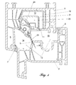
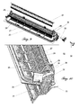
- Fig. 1 is the upper horizontal portion of a forced ventilation window according to the invention with frame profile 1, sash profile 2, steel reinforcement 12 and inventive fan module 20 is shown.
- Folding area 13 between window frame profile 1 and sash profile 2 is bounded to the outside by the frame overlap 6 and the outer stop seal 7 and the interior of the room by the inner stop seal 8 and divided by the center seal 3 in a weather-side seaming area 14 and a room-side folding area 15.
- the center seal 3 is thereby inserted or extruded with its foot region into the center seal receiving groove 4 of the frame profile 1 in the PCE method ( Fig. 2 ) and is tightly against the center seal stopper 5 of the wing frame profile 2.
- the air supply to the weather-side seaming area 14 is offset laterally - in Fig. 1 not shown - by an interruption of the outer stop seal 7.
- the connection between the room-side folding area 15 and the interior of the room is - as well known from the prior art - possibly also laterally offset either via a notch of the inner stop seal 8 or by a milling in the Room-side rollover of the sash profile 2 (in Fig. 1 not shown).
- the frame profile 1 has to stiffen a large hollow chamber 10 (steel reinforcement chamber) for receiving the steel reinforcement 12.
- the steel reinforcement 12 is - as known from the prior art - by means of corresponding screw 17 with the frame profile 1 shear-resistant connected ( Fig. 2 ).
- the casement profile (2) also has a corresponding steel reinforcement (in Fig. 1 not shown).
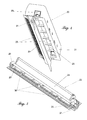
- the fan module 20 is in Fig. 4 shown in a spatial view in more detail. It consists of the fan housing 21 and the fan insert 22 (FIG. Fig. 5 ).
- the fan insert 22 in turn is composed of the fan cover 23, the fan flap 24 and the thumbwheel 32 and the axle pin 35 ( Fig. 9 ).
- the air guide takes place when the ventilation flap 24 is open, starting from the weather-side folding area 14, first via the entry slots 27 into the fan module 20, then through the gap between the fan flap 24 and stop bar 25 in the region of the fan housing 21 facing the interior of the room and then through the outlet slots 28 in the room-side folding region 15.
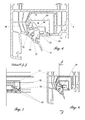
- the fan flap depends on gravity lower gravity following approximately vertically downwards, as in Fig. 6 shown. When a defined amount of air is exceeded, the fan flap 24 moves counterclockwise until it stops at the stop bar 25 (FIG. Fig. 6 ) created and the ventilation path thereby at least largely shuts off.
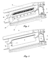
- the assembled fan module 20 becomes - as in FIGS. 2 and 3 shown - in an opening (cutout 9) of the wall 11 of the hollow chamber 10 (steel reinforcement chamber) clipped, so that the fan module 20 extends to a predominant Anteuil its volume in the steel reinforcement chamber.
- the cutout 9 also interrupts the center seal region of the frame profile 1.
- the fan module 20 therefore has a continued center seal 31, which continues the contour of the interrupted center seal 3 and the center seal plane 16 closes again. The air can therefore not flow directly from the weather-side seaming region 14 into the room-side seaming region 15, but only through the fan module 20.
- the largest part of the fan module 20 is sunk in the hollow chamber 10 of the frame profile 1, so that it does not appear optically disturbing.
- the fan housing 21 is designed to be at least largely dense and, for example, sealed by a molded soft elastic seal or a sealing compound against the wall 11 of the hollow chamber 10. The air guide is thus not directly through the steel reinforcement chamber 10, but only through the inserted into the steel reinforcement chamber 10 fan module 20th
- the inlet slots 27 are arranged side by side in the illustrated example with a smaller distance. If necessary, however, the outlet slots 28 can be arranged correspondingly close to each other.
- the fan module 20 shown in the figures has - according to the preferred embodiment of the invention - additional means limiting the pendulum deflection of the pendulum-mounted fan valve 24.
- a thumbwheel 32 is set, which can limit the pendulum movement of the fan valve 24 with a locking pin 33.
- the thumbwheel 32 is mounted on the pivot pin 35 itself pivotally, wherein the locking pin 33 - as in FIGS. 9 and 10 recognizable - engages through the guide slot 36 and projects into the pendulum region of the fan valve 24.
- the adjusting wheel 32 is rotated in the clockwise direction to the outermost position and secured in this position via small knobs 34 in the guide slot 36 against unintentional adjustment. In this position, the fan valve 24 is pressed against the stop bar 25, so that the ventilation path is interrupted.
- the thumbwheel 32 is rotated counterclockwise to the outermost position and secured in this position also via small nubs 34 in the guide slot 36 against unintentional adjustment.
- the locking pin 33 is outside the pivoting range of the fan valve 24, so that at low air pressure differences between the weather-side seaming area 14 and the room-side seaming area 15 a corresponding ventilation can take place, said ventilation automatically at a defined pressure difference is exceeded by the fan valve 24 is closed.
- the setting wheel 32 is inserted with the locking pin 33 in the guide slot 36 and secured to the axle 35.
- the fan valve 24 is in the guide grooves 26 of both sides of the fan cover 23rd arranged arms engaged and the so completed fan insert 22 inserted into the fan housing 21.
- the clips 30, which engage in corresponding recesses in the interior of the fan housing 21.
- the complete fan module 20 is in turn used with the aid of the front side of the fan housing 21 projecting clips 29 in the opening 9 of the wall 11 of the hollow chamber 10 of the frame profile 1.
- the clips 29 are shaped so that the entire fan module 20 at any time for maintenance or cleaning purposes from the opening 9 can be removed again.
- the continued center seal 31 of the fan module 20 may be integrally connected as needed in the two-component injection molding process with the fan cover 23 or subsequently inserted by inserting a short center seal piece in a groove 37 of the fan cover 23.
Abstract
Um bei Mitteldichtungssystemen hohe Luftaustauschmengen ohne störende Einbauten im Falzbereich zu ermöglichen, wird ein zwangsbelüftetes Fenster oder Tür vorgeschlagen, mit einem aus Blendrahmenprofilen (1) gebildeten Blendrahmen, einem aus Flügelrahmenprofilen (2) gebildeten Flügel, einem sich zwischen Blendrahmen und Flügelrahmen erstreckenden Falzbereich (13), einer Mitteldichtung (3), die den Falzbereich (13) in einen wetterseitigen (14) und einen raumseitigen Falzbereich (15) trennt, wobei die Luftführung durch den wetterseitigen (14) und den raumseitigen Falzbereich (15) erfolgt, sowie Mitteln zur selbstständigen Begrenzung der Luftmenge bei Überschreiten einer definierten Druckdifferenz zwischen dem wetterseitigen (14) und dem raumseitigen Falzbereich (15), wobei die Blendrahmenprofile (1) und/oder die Flügelrahmenprofile (2) wenigstens eine Hohlkammer (10) aufweisen, die über eine Wandung (11) an den wetterseitigen (14) und an den raumseitigen Falzbereich (15) angrenzt. Die an den wetterseitigen (14) und den raumseitigen Falzbereich (15) angrenzende Wandung (11) der Hohlkammer (10) weist eine Durchbrechung (9) auf, in die ein Lüftermodul (20) eingesetzt ist, wobei das Lüftermodul (20) ein gegenüber der Hohlkammer (10) wenigstens weitgehend abgedichtetes Lüftergehäuse (21) und Öffnungen (Eintrittsschlitze 27, Austrittsschlitze 28) aufweist, die durch das Lüftermodul (20) eine Luftführung zwischen dem wetterseitigen (14) und dem raumseitigen Falzbereich (15) ermöglichen.In order to allow high air exchange rates in medium-sealing systems without disturbing installations in the rebate, a forced-ventilated window or door is proposed with a frame made of frame profiles (1), a sash formed from sash profiles (2), a between frame and sash frame extending rebate area (13 ), a center seal (3) which separates the fold region (13) into a weather - side (14) and a room - side fold region (15), the air guide being effected by the weather - side (14) and room - side fold region (15), and means for independent limitation of the air quantity when a defined pressure difference between the weather-side (14) and the room-side fold region (15) is exceeded, wherein the window frame profiles (1) and / or the casement profiles (2) have at least one hollow chamber (10) which is connected via a wall (FIG. 11) on the weather side (14) and on the room side folding area (15) angre complements. The wall (11) of the hollow chamber (10) which adjoins the weather-side (14) and room-side folding region (15) has an opening (9) into which a fan module (20) is inserted, the fan module (20) facing one another the hollow chamber (10) at least substantially sealed fan housing (21) and openings (inlet slots 27, outlet slots 28), which allow through the fan module (20) an air duct between the weather-side (14) and the room-side fold region (15).
Description
Die Erfindung betrifft ein als Mitteldichtungssystem ausgelegtes zwangsbelüftetes Fenster oder Tür mit einem aus Blendrahmenprofilen gebildeten Blendrahmen, einem aus Flügelrahmenprofilen gebildeten Flügel, einem sich zwischen Blendrahmen und Flügelrahmen erstreckenden Falzbereich, einer Mitteldichtung, die den Falzbereich in einen wetterseitigen und einen raumseitigen Falzbereich trennt, wobei die Luftführung durch den wetterseitigen und den raumseitigen Falzbereich erfolgt, sowie Mitteln zur selbstständigen Begrenzung der Luftmenge bei Überschreiten einer definierten Druckdifferenz zwischen dem wetterseitigen und dem raumseitigen Falzbereich, wobei die Blendrahmenprofile und/oder die Flügelrahmenprofile wenigstens eine Hohlkammer aufweisen, die über eine Wandung an den wetterseitigen und den raumseitigen Falzbereich angrenzt.The invention relates to a compulsorily ventilated window or door designed as a central sealing system comprising a frame made of frame profiles, a folding area extending between frame and sash, a center seal which separates the folding area into a weather-side and a room-side folding area, wherein the Air duct through the weather-side and the room-side folding area is carried out, and means for autonomously limiting the amount of air at a defined pressure difference between the weather-side and the room-side folding area, wherein the frame profiles and / or the sash profiles have at least one hollow chamber, which via a wall on the weather side and adjacent the room-side fold area.
Der Einsatz wärmegedämmter Fenster mit verbesserter Fugendichtigkeit führt häufig, insbesondere bei Einsatz in Feuchträumen wie Bädern und Küchen, zu vermehrten Feuchtigkeitsschäden wie Schimmelpilzbefall, sofern nicht eine regelmäßige und ausreichende Belüftung der Räume sichergestellt werden kann. Es ist deshalb bekannt, Fenster mit einer Zwangsbelüftung auszustatten, die eine Mindestbelüftung der Räume sicherstellt. Um bei höheren Luftdruckdifferenzen zwischen Innenraum und Gebäudeäußerem infolge hoher Windgeschwindigkeiten unerwünscht hohe Volumenströmen der ausgetauschten Luft und damit verbundene Zugerscheinungen zu vermeiden, werden Mittel zur selbstständigen Begrenzung der Luftmenge bei Überschreiten einer definierten Druckdifferenz eingesetzt.The use of heat-insulated windows with improved joint tightness often leads, especially when used in damp rooms such as bathrooms and kitchens, to increased moisture damage such as mold infestation, unless regular and adequate ventilation of the rooms can be ensured. It is therefore known to provide windows with a forced ventilation, which ensures a minimum ventilation of the rooms. In order to avoid undesirable high volume flows of the exchanged air and associated draft phenomena at higher differences in air pressure between the interior and building exterior due to high wind speeds, means for autonomously limiting the amount of air are used when exceeding a defined pressure difference.
Aus der
Aus der
Aus der
Einen ähnlichen Ansatz verfolgt die
Aufgabe der vorliegenden Erfindung ist es, ein zwangsbelüftetes Fenster mit Lüftermodul und ein Lüftermodul hierfür zur Verfügung zu stellen, das für hohe Luftaustausch-Mengen bei geringen Luftdruckdifferenzen zwischen der wetterseitigen und der raumseitigen Falzkammer einsetzbar ist, ohne störende Einbauten im Falzbereich auskommt und universell für Mitteldichtungssysteme einsetzbar ist.Object of the present invention is to provide a forced-ventilated window with fan module and a fan module for this purpose, which can be used for high air exchange rates at low air pressure differences between the weather-side and the room-side folding chamber, without interfering internals in the rebate and manages universally for central sealing systems can be used.
Die Erfindung löst diese Aufgabe durch ein zwangsbelüftetes Fenster mit Tür gemäß Anspruch 1, bevorzugt mit einem oder mehreren der Merkmale der abhängigen Ansprüche 2 bis 8, sowie durch ein Lüftermodul nach Anspruch 9, bevorzugt mit einem oder mehreren der Merkmale des abhängigen Anspruchs 10.The invention solves this problem by a forced-ventilated window with door according to
Kern der vorliegenden Erfindung ist der Einsatz eines Lüftermoduls, das in eine entsprechende Durchbrechung der falzseitig die Verstärkungskammer begrenzenden Wandung des Blendrahmenprofils oder des Flügelrahmenprofils eingesetzt wird und bei geöffneter Lüfterklappe einen Lüftungsweg zwischen dem wetterseitigen Falzbereich und dem raumseitigen Falzbereich freigibt. Die Luftführung erfolgt somit nicht direkt durch die Verstärkungskammer, sondern nur durch ein in die Verstärkungskammer eingesetztes Lüftermodul. Unter "in die Verstärkungskammer eingesetztes Lüftermodul" im Sinne der vorliegenden Erfindung wird verstanden, dass sich im eingesetzten Zustand der überwiegende Teil des Volumens des Lüftermoduls in der Verstärkungskammer befindet. Bevorzugt befinden sich mindestens 75 % des Volumens des Lüftermoduls in der Verstärkungskammer.Core of the present invention is the use of a fan module, which is inserted into a corresponding opening of the falzseitig the reinforcing chamber bounding wall of the frame profile or the sash profile and releases a ventilation path between the weather-side seaming area and the room-side seaming area when the fan door is open. The air guide is thus not directly through the amplification chamber, but only by a fan module inserted into the amplification chamber. The term "fan module inserted into the amplification chamber" in the sense of the present invention is understood to mean that, in the inserted state, the major part of the volume of the fan module is located in the amplification chamber. Preferably, at least 75% of the volume of the fan module is in the boost chamber.
Nach einer bevorzugten Ausführungsform der Erfindung unterbricht die Durchbrechung der die Verstärkungskammer begrenzenden Wandung des Blendrahmenprofils oder des Flügelrahmenprofils zugleich auch die Mitteldichtungsebene, so dass das erfindungsgemäße Lüftermodul sehr einfach eingesetzt werden kann. Um die Mitteldichtungsebene wieder zu schließen, weist das Lüftermodul bevorzugt eine weitergeführte Mitteldichtung - im weiteren auch Mitteldichtungsabschnitt genannt - auf, die sich nahtlos an die am Blendrahmenprofil bzw. am Flügelrahmenprofil befestigte Mitteldichtung anschließt.According to a preferred embodiment of the invention, the opening of the reinforcing chamber bounding wall of the frame profile or the sash profile at the same time interrupts the middle sealing plane, so that the fan module according to the invention can be used very easily. In order to close the middle seal plane again, the fan module preferably has a continued one Center seal - also referred to as the center seal section - on, which connects seamlessly to the attached to the frame profile or the sash profile center seal.
Nach einer bevorzugten Ausführungsform der Erfindung ist in dem Lüftermodul eine Lüfterklappe eingesetzt, die bei Überschreiten einer definierten Druckdifferenz zwischen dem wetterseitigen Falzbereich und dem raumseitigen Falzbereich ausgelenkt wird und dabei den Lüftungsweg durch das Lüftermodul schließt. Besonders bevorzugt wird die Lüfterklappe alleine durch ihre Schwerkraft in die Ruhestellung, d. h. die Stellung mit offenem Lüftungsweg, geschwenkt. Bei steigendem Luftdurchsatz - entsprechend einer steigenden Luftdruckdifferenz zwischen dem wetterseitigen Falzbereich und dem raumseitigen Falzbereich - wird bei dieser bevorzugten Ausführungsform der Erfindung die Lüfterklappe aus ihrer Schwerpunktslage geschwenkt und im Endpunkt ihrer Schwenkbewegung gegen eine Anschlagleiste bewegt, an der die Lüfterklappe dann dichtend anliegt und somit den Lüftungsweg schließt. Besonders bevorzugt wird das Anschlagen der Lüfterklappe an der Anschlagleiste beispielsweise durch weichelastische Materialien gedämpft, um Anschlaggeräusche zu minimieren.According to a preferred embodiment of the invention, a ventilation flap is inserted in the fan module, which is deflected when a defined pressure difference between the weather-side seaming area and the room-side seaming area is exceeded, thereby closing the ventilation path through the fan module. Particularly preferably, the fan door alone by its gravity in the rest position, d. H. the position with open ventilation path, pivoted. With increasing air flow - in accordance with an increasing air pressure difference between the weather-side folding area and the room-side rebate - in this preferred embodiment of the invention, the fan flap pivoted from its center of gravity and moved in the end of its pivoting movement against a stop bar on which the fan valve then sealingly abuts and thus the Ventilation path closes. Particularly preferably, the striking of the fan flap is damped at the stop bar, for example, by soft elastic materials to minimize impact noises.
In einer besonders bevorzugten Ausführungsform der Erfindung werden Mittel eingesetzt, die die Pendelauslenkung der pendelt gelagerten Lüfterklappe begrenzen. Je nach Bedarf kann beispielsweise hierdurch die Lüfterklappe zwangsweise in einer Geöffnetstellung, zwangsweise in einer Geschlossenstellung und/ oder auch in einer Mittelposition arretiert werden. Zweckmäßigerweise werden Arretiermittel eingesetzt, die in ihrer Endstellung einrasten oder auf andere Weise gegen versehentliches Verstellen gesichert sind.In a particularly preferred embodiment of the invention, means are used which limit the pendulum deflection of the pendulum-mounted fan flap. Depending on requirements, for example, by this means, the ventilation flap can be locked forcibly in an open position, forcibly in a closed position and / or also in a middle position. Conveniently, locking means are used, which engage in their end position or are secured in other ways against accidental adjustment.
Um eine einfache Montage und für Wartungszwecke Demontage des erfindungsgemäßen Lüftermoduls in die bzw. aus der Durchbrechung der Wandung der Hohlkammer zu ermöglichen, weist das Lüftermodul bevorzugt Mittel zur rastenden Befestigung auf. Das erfindungsgemäße Lüftermodul ermöglicht durch sein bei Bedarf relativ großes Volumen auch bei kleineren Luftdruckdifferenzen zwischen wetterseitigem und raumseitigem Falzbereich relativ hohe Luftaustauschmengen, ohne im Falzbereich zwischen Blendrahmenprofil und Flügelrahmenprofil ästhetisch zu stören. Zugleich wird durch die geschlossene Ausführung eine Kondensatbildung in der (Stahl-) Verstärkungskammer zuverlässig unterbunden, ohne dass spezielle Blend- oder Flügelrahmen mit separater Lüftungskammer notwendig wären.In order to enable a simple assembly and for maintenance purposes disassembly of the fan module according to the invention in or out of the opening of the wall of the hollow chamber, the fan module preferably comprises means for latching attachment. The fan module according to the invention allows by relatively large if necessary volume even with smaller differences in air pressure between weather-side and raumseitigem fold area relatively high air exchange rates, without disturbing aesthetically in the rebate area between frame profile and casement profile. At the same time, condensate formation in the (steel) reinforcement chamber is reliably prevented by the closed design, without the need for special glazing or sash frames with separate ventilation chamber.
Die Erfindung wird nachfolgend anhand eines Ausführungsbeispiels sowie der Zeichnung näher erläutert. Es zeigen dabei:
- Fig. 1
- einen Schnitt durch ein erfindungsgemäßes zwangsbelüftetes Fenster;
- Fig. 2
- einen Abschnitt des oberen horizontalen Blendrahmenholms mit eingesetztem Lüftermodul;
- Fig. 3
- den Abschnitt des oberen horizontalen Blendrahmenholms gemäß
Fig. 2 vor dem Einsetzen des Lüftermoduls; - Fig. 4
- das Lüftermodul;
- Fig. 5
- den Lüftereinsatz;
- Fig. 6
- einen Querschnitt des oberen horizontalen Blendrahmenholms mit eingesetztem Lüftermodul (Lüfterklappe nicht arretiert);
- Fig. 7
- Schnitt JJ gemäß
Fig. 8 ; - Fig. 8
- einen Querschnitt des oberen horizontalen Blendrahmenholms mit eingesetztem Lüftermodul (Lüfterklappe arretiert);
- Fig. 9
- Explosionszeichnung des Lüftereinsatzes;
- Fig. 10
- Detail-Ansicht des zusammengesetzten Lüftereinsatzes (Lüfterklappe nicht arretiert).
- Fig. 1
- a section through an inventive ventilated window;
- Fig. 2
- a portion of the upper horizontal frame spar with inserted fan module;
- Fig. 3
- the section of the upper horizontal frame spar according to
Fig. 2 before installing the fan module; - Fig. 4
- the fan module;
- Fig. 5
- the fan insert;
- Fig. 6
- a cross section of the upper horizontal frame spar with inserted fan module (fan flap not locked);
- Fig. 7
- Cut JJ according to
Fig. 8 ; - Fig. 8
- a cross section of the upper horizontal frame spar with inserted fan module (ventilation flap locked);
- Fig. 9
- Exploded view of the fan tray;
- Fig. 10
- Detail view of the assembled fan insert (ventilation flap not locked).
In
Das Blendrahmenprofil 1 weist zur Versteifung eine große Hohlkammer 10 (Stahlverstärkungskammer) zur Aufnahme der Stahlverstärkung 12 auf. Die Stahlverstärkung 12 wird - wie aus dem Stand der Technik bekannt - mittels entsprechender Verschraubungen 17 mit dem Blendrahmenprofil 1 schubfest verbunden (
Das erfindungsgemäße Lüftermodul 20 ist in
Das zusammengesetzte Lüftermodul 20 wird - wie in
Wie insbesondere in
Um ein Eindringen von Insekten in das Lüftermodul 20 zu verhindern, sind in dem dargestellten Beispiel die Eintrittsschlitze 27 mit geringerem Abstand nebeneinander angeordnet. Bei Bedarf können aber auch die Austrittsschlitze 28 entsprechend eng aneinanderliegend angeordnet werden.In order to prevent ingress of insects into the
Das in den Fig. dargestellte Lüftermodul 20 weist - entsprechend der bevorzugten Ausführungsform der Erfindung - zusätzliche Mittel auf, die die Pendelauslenkung der pendelt gelagerten Lüfterklappe 24 begrenzen. Hierzu wird ein Stellrad 32 ein gesetzt, das mit einem Arretierstift 33 die Pendelbewegung der Lüfterklappe 24 begrenzen kann. Das Stellrad 32 ist dabei über den Achsstift 35 selbst schwenkbar gelagert, wobei der Arretierstift 33 - wie in
In
In den
Die weitergeführte Mitteldichtung 31 des Lüftermoduls 20 kann bei Bedarf z.B. im Zweikomponenten-Spritzgussverfahren einstückig mit dem Lüfterdeckel 23 verbunden sein oder nachträglich durch Einsetzen eines kurzen Mitteldichtungs-Stücks in eine Nut 37 des Lüfterdeckels 23 eingesetzt werden.The continued
- 11
- BlendrahmenprofilFrame profile
- 22
- FlügelrahmenprofilCasement profile
- 33
- MitteldichtungCenter seal
- 44
- Mitteldichtungsaufnahmenutcenter seal
- 55
- MitteldichtungsanschlagCenter seal
- 66
- BlendrahmenüberschlagFrame rollover
- 77
- äußere Anschlagdichtungouter stop seal
- 88th
- innere Anschlagdichtunginner stop seal
- 99
- Ausfräsung (Durchbrechung)Cut-out (opening)
- 1010
- Hohlkammer ((Stahl-)Verstärkungskammer)Hollow chamber ((steel) reinforcement chamber)
- 1111
- Wandung HohlkammerWall hollow chamber
- 1212
- Stahlverstärkungsteel reinforcement
- 1313
- Falzbereichfolding area
- 1414
- wetterseitiger Falzbereichweather-side fold area
- 1515
- raumseitiger Falzbereichroom-side fold area
- 1616
- MitteldichtungsebeneCenter seal level
- 1717
- Verschraubung StahlverstärkungScrew connection steel reinforcement
- 1818
- entfälltdeleted
- 1919
- entfälltdeleted
- 2020
- Lüftermodulfan module
- 2121
- Lüftergehäusefan housing
- 2222
- Lüftereinsatzfan tray
- 2323
- Lüfterdeckelfan cover
- 2424
- Lüfterklappeventilation flap
- 2525
- Anschlagleistestop bar
- 2626
- Führungsnutenguide
- 2727
- Eintrittsschlitzeinlet slots
- 2828
- Austrittsschlitzeexit slots
- 2929
- Klipsclip
- 3030
- Klipsclip
- 3131
- weitergeführte MitteldichtungContinued center seal
- 3232
- Stellradthumbwheel
- 3333
- Arretierstiftlocking pin
- 3434
- Noppenburl
- 3535
- Achsstiftaxle pin
- 3636
- Führungsschlitzguide slot
- 3737
- Nutgroove
Claims (10)
Priority Applications (2)
| Application Number | Priority Date | Filing Date | Title |
|---|---|---|---|
| PL14171035T PL2811102T3 (en) | 2013-06-03 | 2014-06-03 | Window with ventilation module |
| EP14171035.0A EP2811102B1 (en) | 2013-06-03 | 2014-06-03 | Window with ventilation module |
Applications Claiming Priority (2)
| Application Number | Priority Date | Filing Date | Title |
|---|---|---|---|
| EP13170336.5A EP2811101A1 (en) | 2013-06-03 | 2013-06-03 | Window with forced ventilation with fan module and fan unit therefor |
| EP14171035.0A EP2811102B1 (en) | 2013-06-03 | 2014-06-03 | Window with ventilation module |
Publications (2)
| Publication Number | Publication Date |
|---|---|
| EP2811102A1 true EP2811102A1 (en) | 2014-12-10 |
| EP2811102B1 EP2811102B1 (en) | 2019-08-07 |
Family
ID=48537863
Family Applications (2)
| Application Number | Title | Priority Date | Filing Date |
|---|---|---|---|
| EP13170336.5A Withdrawn EP2811101A1 (en) | 2013-06-03 | 2013-06-03 | Window with forced ventilation with fan module and fan unit therefor |
| EP14171035.0A Active EP2811102B1 (en) | 2013-06-03 | 2014-06-03 | Window with ventilation module |
Family Applications Before (1)
| Application Number | Title | Priority Date | Filing Date |
|---|---|---|---|
| EP13170336.5A Withdrawn EP2811101A1 (en) | 2013-06-03 | 2013-06-03 | Window with forced ventilation with fan module and fan unit therefor |
Country Status (2)
| Country | Link |
|---|---|
| EP (2) | EP2811101A1 (en) |
| PL (1) | PL2811102T3 (en) |
Cited By (4)
| Publication number | Priority date | Publication date | Assignee | Title |
|---|---|---|---|---|
| CN106801575A (en) * | 2017-03-10 | 2017-06-06 | 司晓巍 | Stile in a kind of multifunctional new wind |
| CN106884606A (en) * | 2017-03-23 | 2017-06-23 | 合肥协耀玻璃制品有限公司 | A kind of preferable aluminum window of ventilation effect |
| EP3800317A1 (en) * | 2019-10-04 | 2021-04-07 | SCHÜCO International KG | Window with a ventilation duct |
| WO2021064140A1 (en) * | 2019-10-04 | 2021-04-08 | SCHÜCO International KG | Window having a ventilation duct |
Families Citing this family (3)
| Publication number | Priority date | Publication date | Assignee | Title |
|---|---|---|---|---|
| DE202015000271U1 (en) * | 2015-01-16 | 2016-04-19 | SCHÜCO International KG | Folding fan for a window or door and window or door with such a fan |
| DE102020106696A1 (en) * | 2019-10-04 | 2021-04-08 | SCHÜCO International KG | Window with a ventilation duct |
| DE102020120661A1 (en) * | 2019-10-04 | 2021-04-08 | SCHÜCO International KG | Window with a ventilation duct |
Citations (7)
| Publication number | Priority date | Publication date | Assignee | Title |
|---|---|---|---|---|
| DE19610428C2 (en) | 1996-03-16 | 2000-07-06 | Huels Troisdorf | Ventilated window |
| DE19929133C2 (en) | 1998-06-25 | 2001-06-28 | Christel Becks | Plastic window made of sash and frame |
| DE20201000U1 (en) | 2002-01-24 | 2002-06-13 | Elfgen Gerd | milling device |
| DE202005002132U1 (en) * | 2005-02-10 | 2006-03-23 | Rehau Ag + Co | Frame assembly and air flow limiting device for this purpose |
| DE202006004712U1 (en) | 2006-03-22 | 2006-06-22 | Aluplast Gmbh | Window or door with ventilation |
| DE20221802U1 (en) | 2002-09-25 | 2007-11-22 | Profine Gmbh | Forced ventilation window with airflow limitation |
| DE202010002002U1 (en) * | 2010-02-05 | 2010-06-02 | Veka Ag | Ventilation control device for windows and doors |
-
2013
- 2013-06-03 EP EP13170336.5A patent/EP2811101A1/en not_active Withdrawn
-
2014
- 2014-06-03 EP EP14171035.0A patent/EP2811102B1/en active Active
- 2014-06-03 PL PL14171035T patent/PL2811102T3/en unknown
Patent Citations (8)
| Publication number | Priority date | Publication date | Assignee | Title |
|---|---|---|---|---|
| DE19610428C2 (en) | 1996-03-16 | 2000-07-06 | Huels Troisdorf | Ventilated window |
| DE19929133C2 (en) | 1998-06-25 | 2001-06-28 | Christel Becks | Plastic window made of sash and frame |
| DE20201000U1 (en) | 2002-01-24 | 2002-06-13 | Elfgen Gerd | milling device |
| DE20221802U1 (en) | 2002-09-25 | 2007-11-22 | Profine Gmbh | Forced ventilation window with airflow limitation |
| DE202005002132U1 (en) * | 2005-02-10 | 2006-03-23 | Rehau Ag + Co | Frame assembly and air flow limiting device for this purpose |
| DE202006004712U1 (en) | 2006-03-22 | 2006-06-22 | Aluplast Gmbh | Window or door with ventilation |
| EP1837477B1 (en) | 2006-03-22 | 2011-06-29 | aluplast GmbH | Window or door with ventilation |
| DE202010002002U1 (en) * | 2010-02-05 | 2010-06-02 | Veka Ag | Ventilation control device for windows and doors |
Cited By (7)
| Publication number | Priority date | Publication date | Assignee | Title |
|---|---|---|---|---|
| CN106801575A (en) * | 2017-03-10 | 2017-06-06 | 司晓巍 | Stile in a kind of multifunctional new wind |
| CN106884606A (en) * | 2017-03-23 | 2017-06-23 | 合肥协耀玻璃制品有限公司 | A kind of preferable aluminum window of ventilation effect |
| CN106884606B (en) * | 2017-03-23 | 2019-06-07 | 合肥协耀玻璃制品有限公司 | A kind of preferable aluminum window of ventilation effect |
| EP3800317A1 (en) * | 2019-10-04 | 2021-04-07 | SCHÜCO International KG | Window with a ventilation duct |
| WO2021064140A1 (en) * | 2019-10-04 | 2021-04-08 | SCHÜCO International KG | Window having a ventilation duct |
| CN114502814A (en) * | 2019-10-04 | 2022-05-13 | 许克国际两合公司 | Window with ventilating duct |
| CN114502814B (en) * | 2019-10-04 | 2023-12-15 | 许克国际两合公司 | Window, ventilation box and method for forming ventilation duct in window |
Also Published As
| Publication number | Publication date |
|---|---|
| EP2811101A1 (en) | 2014-12-10 |
| PL2811102T3 (en) | 2020-02-28 |
| EP2811102B1 (en) | 2019-08-07 |
Similar Documents
| Publication | Publication Date | Title |
|---|---|---|
| EP2811102B1 (en) | Window with ventilation module | |
| EP2791452B1 (en) | Ventilation device for a window or a door | |
| EP3165701B1 (en) | Ventilation element for window with flap acting as chicane | |
| WO1998021436A1 (en) | Window with ventilation louvre mounted in a swinging manner in the fitting groove of the casement | |
| EP1877640B1 (en) | Frame for a window or a door | |
| EP2255058B1 (en) | Top mounted roller shutter box and profile system for such a roller shutter box | |
| EP2386710B1 (en) | Window with drainage opening | |
| EP3165702B1 (en) | Window element with optimized arrangement of forced ventilation | |
| EP1837477B1 (en) | Window or door with ventilation | |
| DE3107234A1 (en) | "WINDOW OR DOOR WITH A BUILT-IN SLIDE VENTILATION" | |
| EP1727957B1 (en) | Airflow limiting device for a force-ventilated window | |
| EP1715133B1 (en) | A tip-over ventilation system for windows | |
| EP1500773B1 (en) | Device for limiting air flow in a forced ventilated window | |
| DE102014110976A1 (en) | Wing overrun ventilator with obliquely displaceable sealing slide | |
| EP1005621B1 (en) | Ventilator for window elements | |
| DE10209696A1 (en) | Forced ventilation window with airflow limitation | |
| DE10244932A1 (en) | Automatically vented window with air flow restrictor which has base body with flap to release ventilation path until closing same by bearing against stop face of centre seal in event of exceeding predetermined pressure difference | |
| EP2886780B1 (en) | Window rebate ventilator | |
| DE102006024803A1 (en) | Connector for temporary air conditioning to window or door of building has opening for pipe and with front and side sections extending over seating face | |
| EP4191147B1 (en) | Air passage with flap pivotable against resistance | |
| EP2764809B1 (en) | Shower partition | |
| EP3929392B1 (en) | Window folding fan | |
| EP2759671A2 (en) | Window ventilator | |
| DE4437849A1 (en) | Insert for window with one or more rotating and=or tilting casements | |
| DE102018007864A1 (en) | Ventilation device |
Legal Events
| Date | Code | Title | Description |
|---|---|---|---|
| PUAI | Public reference made under article 153(3) epc to a published international application that has entered the european phase |
Free format text: ORIGINAL CODE: 0009012 |
|
| 17P | Request for examination filed |
Effective date: 20140603 |
|
| AK | Designated contracting states |
Kind code of ref document: A1 Designated state(s): AL AT BE BG CH CY CZ DE DK EE ES FI FR GB GR HR HU IE IS IT LI LT LU LV MC MK MT NL NO PL PT RO RS SE SI SK SM TR |
|
| AX | Request for extension of the european patent |
Extension state: BA ME |
|
| R17P | Request for examination filed (corrected) |
Effective date: 20150610 |
|
| RBV | Designated contracting states (corrected) |
Designated state(s): AL AT BE BG CH CY CZ DE DK EE ES FI FR GB GR HR HU IE IS IT LI LT LU LV MC MK MT NL NO PL PT RO RS SE SI SK SM TR |
|
| STAA | Information on the status of an ep patent application or granted ep patent |
Free format text: STATUS: EXAMINATION IS IN PROGRESS |
|
| 17Q | First examination report despatched |
Effective date: 20170412 |
|
| GRAP | Despatch of communication of intention to grant a patent |
Free format text: ORIGINAL CODE: EPIDOSNIGR1 |
|
| STAA | Information on the status of an ep patent application or granted ep patent |
Free format text: STATUS: GRANT OF PATENT IS INTENDED |
|
| INTG | Intention to grant announced |
Effective date: 20190124 |
|
| GRAS | Grant fee paid |
Free format text: ORIGINAL CODE: EPIDOSNIGR3 |
|
| GRAA | (expected) grant |
Free format text: ORIGINAL CODE: 0009210 |
|
| STAA | Information on the status of an ep patent application or granted ep patent |
Free format text: STATUS: THE PATENT HAS BEEN GRANTED |
|
| AK | Designated contracting states |
Kind code of ref document: B1 Designated state(s): AL AT BE BG CH CY CZ DE DK EE ES FI FR GB GR HR HU IE IS IT LI LT LU LV MC MK MT NL NO PL PT RO RS SE SI SK SM TR |
|
| REG | Reference to a national code |
Ref country code: GB Ref legal event code: FG4D Free format text: NOT ENGLISH |
|
| REG | Reference to a national code |
Ref country code: CH Ref legal event code: EP Ref country code: AT Ref legal event code: REF Ref document number: 1164143 Country of ref document: AT Kind code of ref document: T Effective date: 20190815 |
|
| REG | Reference to a national code |
Ref country code: DE Ref legal event code: R096 Ref document number: 502014012356 Country of ref document: DE |
|
| REG | Reference to a national code |
Ref country code: IE Ref legal event code: FG4D Free format text: LANGUAGE OF EP DOCUMENT: GERMAN |
|
| REG | Reference to a national code |
Ref country code: NL Ref legal event code: MP Effective date: 20190807 |
|
| REG | Reference to a national code |
Ref country code: LT Ref legal event code: MG4D |
|
| PG25 | Lapsed in a contracting state [announced via postgrant information from national office to epo] |
Ref country code: HR Free format text: LAPSE BECAUSE OF FAILURE TO SUBMIT A TRANSLATION OF THE DESCRIPTION OR TO PAY THE FEE WITHIN THE PRESCRIBED TIME-LIMIT Effective date: 20190807 Ref country code: LT Free format text: LAPSE BECAUSE OF FAILURE TO SUBMIT A TRANSLATION OF THE DESCRIPTION OR TO PAY THE FEE WITHIN THE PRESCRIBED TIME-LIMIT Effective date: 20190807 Ref country code: BG Free format text: LAPSE BECAUSE OF FAILURE TO SUBMIT A TRANSLATION OF THE DESCRIPTION OR TO PAY THE FEE WITHIN THE PRESCRIBED TIME-LIMIT Effective date: 20191107 Ref country code: NL Free format text: LAPSE BECAUSE OF FAILURE TO SUBMIT A TRANSLATION OF THE DESCRIPTION OR TO PAY THE FEE WITHIN THE PRESCRIBED TIME-LIMIT Effective date: 20190807 Ref country code: PT Free format text: LAPSE BECAUSE OF FAILURE TO SUBMIT A TRANSLATION OF THE DESCRIPTION OR TO PAY THE FEE WITHIN THE PRESCRIBED TIME-LIMIT Effective date: 20191209 Ref country code: FI Free format text: LAPSE BECAUSE OF FAILURE TO SUBMIT A TRANSLATION OF THE DESCRIPTION OR TO PAY THE FEE WITHIN THE PRESCRIBED TIME-LIMIT Effective date: 20190807 Ref country code: NO Free format text: LAPSE BECAUSE OF FAILURE TO SUBMIT A TRANSLATION OF THE DESCRIPTION OR TO PAY THE FEE WITHIN THE PRESCRIBED TIME-LIMIT Effective date: 20191107 Ref country code: SE Free format text: LAPSE BECAUSE OF FAILURE TO SUBMIT A TRANSLATION OF THE DESCRIPTION OR TO PAY THE FEE WITHIN THE PRESCRIBED TIME-LIMIT Effective date: 20190807 |
|
| PG25 | Lapsed in a contracting state [announced via postgrant information from national office to epo] |
Ref country code: IS Free format text: LAPSE BECAUSE OF FAILURE TO SUBMIT A TRANSLATION OF THE DESCRIPTION OR TO PAY THE FEE WITHIN THE PRESCRIBED TIME-LIMIT Effective date: 20191207 Ref country code: RS Free format text: LAPSE BECAUSE OF FAILURE TO SUBMIT A TRANSLATION OF THE DESCRIPTION OR TO PAY THE FEE WITHIN THE PRESCRIBED TIME-LIMIT Effective date: 20190807 Ref country code: GR Free format text: LAPSE BECAUSE OF FAILURE TO SUBMIT A TRANSLATION OF THE DESCRIPTION OR TO PAY THE FEE WITHIN THE PRESCRIBED TIME-LIMIT Effective date: 20191108 Ref country code: ES Free format text: LAPSE BECAUSE OF FAILURE TO SUBMIT A TRANSLATION OF THE DESCRIPTION OR TO PAY THE FEE WITHIN THE PRESCRIBED TIME-LIMIT Effective date: 20190807 Ref country code: AL Free format text: LAPSE BECAUSE OF FAILURE TO SUBMIT A TRANSLATION OF THE DESCRIPTION OR TO PAY THE FEE WITHIN THE PRESCRIBED TIME-LIMIT Effective date: 20190807 Ref country code: LV Free format text: LAPSE BECAUSE OF FAILURE TO SUBMIT A TRANSLATION OF THE DESCRIPTION OR TO PAY THE FEE WITHIN THE PRESCRIBED TIME-LIMIT Effective date: 20190807 |
|
| PG25 | Lapsed in a contracting state [announced via postgrant information from national office to epo] |
Ref country code: TR Free format text: LAPSE BECAUSE OF FAILURE TO SUBMIT A TRANSLATION OF THE DESCRIPTION OR TO PAY THE FEE WITHIN THE PRESCRIBED TIME-LIMIT Effective date: 20190807 |
|
| PG25 | Lapsed in a contracting state [announced via postgrant information from national office to epo] |
Ref country code: EE Free format text: LAPSE BECAUSE OF FAILURE TO SUBMIT A TRANSLATION OF THE DESCRIPTION OR TO PAY THE FEE WITHIN THE PRESCRIBED TIME-LIMIT Effective date: 20190807 Ref country code: DK Free format text: LAPSE BECAUSE OF FAILURE TO SUBMIT A TRANSLATION OF THE DESCRIPTION OR TO PAY THE FEE WITHIN THE PRESCRIBED TIME-LIMIT Effective date: 20190807 Ref country code: IT Free format text: LAPSE BECAUSE OF FAILURE TO SUBMIT A TRANSLATION OF THE DESCRIPTION OR TO PAY THE FEE WITHIN THE PRESCRIBED TIME-LIMIT Effective date: 20190807 Ref country code: RO Free format text: LAPSE BECAUSE OF FAILURE TO SUBMIT A TRANSLATION OF THE DESCRIPTION OR TO PAY THE FEE WITHIN THE PRESCRIBED TIME-LIMIT Effective date: 20190807 |
|
| PG25 | Lapsed in a contracting state [announced via postgrant information from national office to epo] |
Ref country code: SK Free format text: LAPSE BECAUSE OF FAILURE TO SUBMIT A TRANSLATION OF THE DESCRIPTION OR TO PAY THE FEE WITHIN THE PRESCRIBED TIME-LIMIT Effective date: 20190807 Ref country code: SM Free format text: LAPSE BECAUSE OF FAILURE TO SUBMIT A TRANSLATION OF THE DESCRIPTION OR TO PAY THE FEE WITHIN THE PRESCRIBED TIME-LIMIT Effective date: 20190807 Ref country code: IS Free format text: LAPSE BECAUSE OF FAILURE TO SUBMIT A TRANSLATION OF THE DESCRIPTION OR TO PAY THE FEE WITHIN THE PRESCRIBED TIME-LIMIT Effective date: 20200224 |
|
| REG | Reference to a national code |
Ref country code: DE Ref legal event code: R097 Ref document number: 502014012356 Country of ref document: DE |
|
| PLBE | No opposition filed within time limit |
Free format text: ORIGINAL CODE: 0009261 |
|
| STAA | Information on the status of an ep patent application or granted ep patent |
Free format text: STATUS: NO OPPOSITION FILED WITHIN TIME LIMIT |
|
| PG2D | Information on lapse in contracting state deleted |
Ref country code: IS |
|
| 26N | No opposition filed |
Effective date: 20200603 |
|
| PG25 | Lapsed in a contracting state [announced via postgrant information from national office to epo] |
Ref country code: SI Free format text: LAPSE BECAUSE OF FAILURE TO SUBMIT A TRANSLATION OF THE DESCRIPTION OR TO PAY THE FEE WITHIN THE PRESCRIBED TIME-LIMIT Effective date: 20190807 |
|
| PG25 | Lapsed in a contracting state [announced via postgrant information from national office to epo] |
Ref country code: MC Free format text: LAPSE BECAUSE OF FAILURE TO SUBMIT A TRANSLATION OF THE DESCRIPTION OR TO PAY THE FEE WITHIN THE PRESCRIBED TIME-LIMIT Effective date: 20190807 |
|
| REG | Reference to a national code |
Ref country code: CH Ref legal event code: PL |
|
| GBPC | Gb: european patent ceased through non-payment of renewal fee |
Effective date: 20200603 |
|
| PG25 | Lapsed in a contracting state [announced via postgrant information from national office to epo] |
Ref country code: LU Free format text: LAPSE BECAUSE OF NON-PAYMENT OF DUE FEES Effective date: 20200603 |
|
| REG | Reference to a national code |
Ref country code: BE Ref legal event code: MM Effective date: 20200630 |
|
| PG25 | Lapsed in a contracting state [announced via postgrant information from national office to epo] |
Ref country code: CH Free format text: LAPSE BECAUSE OF NON-PAYMENT OF DUE FEES Effective date: 20200630 Ref country code: GB Free format text: LAPSE BECAUSE OF NON-PAYMENT OF DUE FEES Effective date: 20200603 Ref country code: IE Free format text: LAPSE BECAUSE OF NON-PAYMENT OF DUE FEES Effective date: 20200603 Ref country code: LI Free format text: LAPSE BECAUSE OF NON-PAYMENT OF DUE FEES Effective date: 20200630 Ref country code: FR Free format text: LAPSE BECAUSE OF NON-PAYMENT OF DUE FEES Effective date: 20200630 |
|
| PG25 | Lapsed in a contracting state [announced via postgrant information from national office to epo] |
Ref country code: BE Free format text: LAPSE BECAUSE OF NON-PAYMENT OF DUE FEES Effective date: 20200630 |
|
| PG25 | Lapsed in a contracting state [announced via postgrant information from national office to epo] |
Ref country code: MT Free format text: LAPSE BECAUSE OF FAILURE TO SUBMIT A TRANSLATION OF THE DESCRIPTION OR TO PAY THE FEE WITHIN THE PRESCRIBED TIME-LIMIT Effective date: 20190807 Ref country code: CY Free format text: LAPSE BECAUSE OF FAILURE TO SUBMIT A TRANSLATION OF THE DESCRIPTION OR TO PAY THE FEE WITHIN THE PRESCRIBED TIME-LIMIT Effective date: 20190807 |
|
| PG25 | Lapsed in a contracting state [announced via postgrant information from national office to epo] |
Ref country code: MK Free format text: LAPSE BECAUSE OF FAILURE TO SUBMIT A TRANSLATION OF THE DESCRIPTION OR TO PAY THE FEE WITHIN THE PRESCRIBED TIME-LIMIT Effective date: 20190807 |
|
| REG | Reference to a national code |
Ref country code: DE Ref legal event code: R081 Ref document number: 502014012356 Country of ref document: DE Owner name: PROFINE GMBH, DE Free format text: FORMER OWNER: PROFINE GMBH, 53840 TROISDORF, DE |
|
| PGFP | Annual fee paid to national office [announced via postgrant information from national office to epo] |
Ref country code: DE Payment date: 20230620 Year of fee payment: 10 Ref country code: CZ Payment date: 20230526 Year of fee payment: 10 |
|
| PGFP | Annual fee paid to national office [announced via postgrant information from national office to epo] |
Ref country code: PL Payment date: 20230526 Year of fee payment: 10 Ref country code: AT Payment date: 20230621 Year of fee payment: 10 |