EP2811084A1 - Crochet latéral et couverture de toit - Google Patents
Crochet latéral et couverture de toit Download PDFInfo
- Publication number
- EP2811084A1 EP2811084A1 EP14401054.3A EP14401054A EP2811084A1 EP 2811084 A1 EP2811084 A1 EP 2811084A1 EP 14401054 A EP14401054 A EP 14401054A EP 2811084 A1 EP2811084 A1 EP 2811084A1
- Authority
- EP
- European Patent Office
- Prior art keywords
- roof
- edge
- foot part
- seitenfalzklammer
- metal strip
- Prior art date
- Legal status (The legal status is an assumption and is not a legal conclusion. Google has not performed a legal analysis and makes no representation as to the accuracy of the status listed.)
- Withdrawn
Links
Images


Classifications
-
- E—FIXED CONSTRUCTIONS
- E04—BUILDING
- E04D—ROOF COVERINGS; SKY-LIGHTS; GUTTERS; ROOF-WORKING TOOLS
- E04D1/00—Roof covering by making use of tiles, slates, shingles, or other small roofing elements
- E04D1/34—Fastenings for attaching roof-covering elements to the supporting elements
-
- E—FIXED CONSTRUCTIONS
- E04—BUILDING
- E04D—ROOF COVERINGS; SKY-LIGHTS; GUTTERS; ROOF-WORKING TOOLS
- E04D1/00—Roof covering by making use of tiles, slates, shingles, or other small roofing elements
- E04D1/29—Means for connecting or fastening adjacent roofing elements
- E04D1/2907—Means for connecting or fastening adjacent roofing elements by interfitted sections
- E04D1/2914—Means for connecting or fastening adjacent roofing elements by interfitted sections having fastening means or anchors at juncture of adjacent roofing elements
- E04D1/2916—Means for connecting or fastening adjacent roofing elements by interfitted sections having fastening means or anchors at juncture of adjacent roofing elements the fastening means taking hold directly on adjacent elements of the same row
-
- E—FIXED CONSTRUCTIONS
- E04—BUILDING
- E04D—ROOF COVERINGS; SKY-LIGHTS; GUTTERS; ROOF-WORKING TOOLS
- E04D1/00—Roof covering by making use of tiles, slates, shingles, or other small roofing elements
- E04D1/34—Fastenings for attaching roof-covering elements to the supporting elements
- E04D2001/3408—Fastenings for attaching roof-covering elements to the supporting elements characterised by the fastener type or material
- E04D2001/3414—Metal strips or sheet metal
-
- E—FIXED CONSTRUCTIONS
- E04—BUILDING
- E04D—ROOF COVERINGS; SKY-LIGHTS; GUTTERS; ROOF-WORKING TOOLS
- E04D1/00—Roof covering by making use of tiles, slates, shingles, or other small roofing elements
- E04D1/34—Fastenings for attaching roof-covering elements to the supporting elements
- E04D2001/3452—Fastenings for attaching roof-covering elements to the supporting elements characterised by the location of the fastening means
- E04D2001/3461—Fastenings for attaching roof-covering elements to the supporting elements characterised by the location of the fastening means on the lateral edges of the roof covering elements
-
- E—FIXED CONSTRUCTIONS
- E04—BUILDING
- E04D—ROOF COVERINGS; SKY-LIGHTS; GUTTERS; ROOF-WORKING TOOLS
- E04D1/00—Roof covering by making use of tiles, slates, shingles, or other small roofing elements
- E04D1/34—Fastenings for attaching roof-covering elements to the supporting elements
- E04D2001/347—Fastenings for attaching roof-covering elements to the supporting elements characterised by the fastening pattern
- E04D2001/3482—Fastenings for attaching roof-covering elements to the supporting elements characterised by the fastening pattern the fastening means taking hold directly on elements of succeeding rows and fastening them simultaneously to the structure
Definitions
- the invention relates to a sofalzklammer for securing roofing parts on the battens of a roof, which consists of roof battens, wherein the roof covering parts on a longitudinal side edge edge have a side fold, wherein the isfalzklammer has a hook-like head portion for engaging the Sofalzes and a foot portion for engaging behind a roof batten, wherein the isfalzklammer integrally consists of a metal strip, at the first narrow end portion of the hook-like head portion is bent and at its opposite second narrow end portion, the foot part is bent, the headboard and foot are bent in the same orientation of the metal strip, and the foot part at its rear the roof batten certain corresponding cut out of the metal strip edge has a first sharp edge or tip.
- the invention relates to a roof covering with a battens from a A plurality of roof battens arranged transversely to a roof pitch, on the upper side of which the roof covering parts are preferably laid at the upper end area of these underside hanging humps, the upper end areas of the roof covering parts of a roof pitch direction lower row from the lower end areas of a roof pitch direction upper row of roof covering parts imbricated, wherein each roofing part further comprises a 39falz at a first longitudinal edge edge and at a second longitudinal edge edge a matching hook strip, and the sofalz a roofing part is hooked to the hook strip of an adjacent roofing part, each in a 39falz a 39falzklammer with a hook-like headboard is used and engages behind a batten with a foot, wherein the Sofalzklammer consists of a rectangular sheet metal strip, at the first narrow Endbe rich the hook-like head part is bent and at the opposite this second narrow end portion of the foot is bent, headboard and foot are
- the present invention seeks to provide a (falzklammer generic type that can be provided at low cost, which is extremely easy to install and prevents rotation of the roofing parts under wind load.
- the metal strip between the headboard and foot has a first cutout for the upper peripheral edge of a roof covering part and a second cutout for a side area of the roof lath.
- the The sofalzklammer invention is formed from a metal strip, preferably made of sheet steel.
- the one-piece design of the sofalzklammer leads to a cost-effective production.
- the sheet metal strip consists of a substantially rectangular sheet metal portion, at the first narrow end portion of the hook-like head portion is bent and at its opposite second narrow end portion, the foot part is bent. Both the head part and the foot part are bent to the same side of the metal strip out, so they protrude from the same side of the metal strip.
- the foot part at his particular for reaching behind a roof batten, according to the Sheet metal edge cut edge on a first sharp edge or point on.
- Such a sofalzklammer is extremely easy to assemble, as this only needs to be hooked on the Sofalz a roofing part and can be moved along the roof covering part until the foot engages behind the corresponding batten.
- the displacement of the Sofalzklammer is extremely simple and appropriate.
- the foot part engages in the material of the roof batten or the like, but it is sufficient if this area engages behind the batten.
- roofing parts are lifted by wind from the roof battens, which is quite possible with the laying direction upper end portion, which is hung with projections on a batten, this does not lead to a rotation of the plate.
- the first sharp edge or tip of the foot part firmly engages in the material of the roof batten. This intervention is further enhanced by the forces exerted by wind suction on the roofing panel.
- the metal strip between the headboard and foot has a first cutout for the upper peripheral edge of a roof covering part and a second cutout for a side region of the roof batten, can be cut and formed from a rectangular sheet metal section a corresponding sofalzklammer, the cutouts for the correct mounting and the desired arrangement of the foot part are helpful.
- the sheet metal strip is formed straight and planar.
- the second cutout ends in front of the foot part, so that an approximately parallel to the peripheral edge of the foot part directed second peripheral edge has remained, which preferably has a second sharp edge or tip.
- This second sharp edge or point lies in the region spanned by the metal strip, ie not in the bent foot part. It is thus formed at a distance from the first sharp edge or tip a second sharp edge or tip that should not come in the laying of Sofalzklammer engaged with the roof batten or the like or must come. Only when the roofing parts are subjected to wind suction, this second sharp edge or tip is also engaged on the roof lath, whereby a further obstacle is formed in order to prevent twisting of the roofing parts against the lathing.
- the second sharp edge or tip is at least slightly opposite the first sharp edge or tip.
- the metal strip in the region of the first cutout longitudinally has stiffening beads which extend into the vicinity of the head part and the foot part.
- the foot part is formed by a U-shaped turn of the sheet metal strip, the first leg is a straight extension of the metal strip and the second, the first sharp edge or tip having thighs directed parallel thereto.
- the head part is hook-like formed with two legs and that the distance between the two legs of the foot part from each other is greater than the distance between the legs of the hook-like head part from each other.
- the object of the invention is achieved in that the sofalzklammer located in mounting target position with a first located between the headboard and footer neckline the upper edge of a roof mounted under a roof covering part of a top row roofing part of a lower row and engages with a second cutout engages laterally over the batten and engages with the foot behind the batten, so that the first edge or tip is arranged without contact at a small distance or with a light touch on the underside of the batten.
- a veryfalzklammer 1 for securing roofing parts 2 on the battens of a roof, the latter consists of battens 3.
- the roofing parts 2 have at a longitudinal edge edge on a side fold 4, wherein the sofalzklammer 1 has a hook-like head part 5 for engaging over the sofalzes 4 and a foot part 6 for engaging behind a roof batten 3.
- the sofalzklammer 1 is integrally formed from a substantially rectangular sheet-metal strip, at the first narrow end portion of the hook-like head portion 5 is bent and at its opposite second narrow end portion, the foot part 6 is bent.
- the head part 5 and the foot part 6 are each bent in the same orientation of the metal strip, so protrude to the same side from the metal strip.
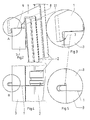
- the foot part 6 has at its intended for engaging behind a roof batten, according to the sheet metal strip cut edge on a first sharp edge or tip 7 on. As in the FIGS. 1a to 1f clearly visible, the sheet metal strip is straight and planar. He has between the head part 5 and foot 6, a first cutout 8 for the upper peripheral edge of a roof covering part 2 and a second cutout 9 for a side region of the roof batten.
- the second cutout 9 ends before the foot part 6, so that an approximately parallel to the peripheral edge of the foot part 6 directed second edge edge has remained, which preferably has a second sharp edge or tip 10.
- This second sharp edge or tip 10 is slightly opposite the first sharp edge or tip 7.
- the sheet-metal strip may have stiffening beads along its longitudinal edge, which extend into the vicinity of the head part 5 and the foot part 6.
- the foot part 6 is formed by a U-shaped bend of the metal strip, the first leg is a straight extension of the metal strip and the second, the first sharp edge or tip 7 having thighs is preferably directed parallel.
- the legs can also be slightly divergent or converging directed to each other.
- the distance between the two legs of the foot part 6 from each other is preferably greater than that Distance between the legs that form the hook-shaped head part 5.
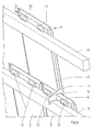
- roofing consists of a lathing of a plurality of transversely arranged to a roof pitch roof battens 3, are placed on the roofing parts 2, each with two at the upper end of this underside provided hanging lugs 11.
- the upper end portion of the roof covering parts 2, a lower row in the roof pitch direction are overlapped by the lower end portions of a top row of roofing parts 2 in the roof pitch direction.
- Each roof covering part 2 has a side fold 4 at a first longitudinal edge edge and a hook strip 12 matching thereto at a second longitudinal edge edge.
- the adjacent roofing parts of a row are hooked to the hook bar 12 each in a side fold 4 of the adjacent roofing part 2.
- the Sofalzklammer 1 is hooked in a corresponding arrangement with its head part 5 in the sofalz 4 of a roof covering part 2, while the foot part 6 located in the mounting target position with the first located between the head part 5 and 6 foot section 8 the upper edge of a located under the roofing part 2, on a roof batten 3 hooked roofing part 2 overlaps.
- the second cutout 9 engages laterally over the roof batten 3 and with the foot part 6 behind the batten 3, so that the tip 7 or edge without touching slight distance or even with light touch on the underside of the roof batten 3 is applied.
- the Sofalzklammer 1 is placed on the side fold 4 with its head part 5 and then moved in the direction of the lower layer of roofing parts until the position is taken, as for example in FIG. 6 and FIG. 11 is shown.
- FIGS. 2 to 6 the installation situation without wind is shown.
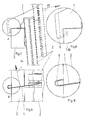
- FIGS. 7 to 11 a situation in which wind force acts in the direction of arrow 13 on the roof covering parts 2.
- the sofalzklammer is claimed to train, because the head part 5 is coupled to the roof covering part 2 in the region of the side fold 4 and the foot part 6 of the sofalzklammer 1 engages behind the roof batten 3.
- the head part 5 is coupled to the roof covering part 2 in the region of the side fold 4 and the foot part 6 of the sofalzklammer 1 engages behind the roof batten 3.
- not only the first sharp edge or tip 7, but also the second sharp edge or tip 10 digs into the material of the batten 3.
- a bending moment in the direction of arrow 14 acts on the sofalzklammer 1, as in FIG. 9 is shown, whereby the cohesion of the elements is promoted. This results, as in FIG.
Landscapes
- Engineering & Computer Science (AREA)
- Mechanical Engineering (AREA)
- Architecture (AREA)
- Civil Engineering (AREA)
- Structural Engineering (AREA)
- Roof Covering Using Slabs Or Stiff Sheets (AREA)
Applications Claiming Priority (1)
| Application Number | Priority Date | Filing Date | Title |
|---|---|---|---|
| DE102013105864.7A DE102013105864B3 (de) | 2013-06-06 | 2013-06-06 | Seitenfalzklammer |
Publications (1)
| Publication Number | Publication Date |
|---|---|
| EP2811084A1 true EP2811084A1 (fr) | 2014-12-10 |
Family
ID=50884844
Family Applications (1)
| Application Number | Title | Priority Date | Filing Date |
|---|---|---|---|
| EP14401054.3A Withdrawn EP2811084A1 (fr) | 2013-06-06 | 2014-05-06 | Crochet latéral et couverture de toit |
Country Status (2)
| Country | Link |
|---|---|
| EP (1) | EP2811084A1 (fr) |
| DE (1) | DE102013105864B3 (fr) |
Families Citing this family (1)
| Publication number | Priority date | Publication date | Assignee | Title |
|---|---|---|---|---|
| DE202015104245U1 (de) * | 2015-08-12 | 2015-09-01 | Friedrich Ossenberg-Schule Gmbh + Co. Kg | Befestigungsklammer |
Citations (4)
| Publication number | Priority date | Publication date | Assignee | Title |
|---|---|---|---|---|
| DE7806263U1 (de) * | 1978-03-02 | 1978-07-13 | Braas & Co Gmbh, 6000 Frankfurt | Sturmklammer zum befestigen von dachsteinen |
| NL9200632A (nl) * | 1992-04-03 | 1993-11-01 | Bove Draadprodukten Bv | Panhaak. |
| DE19522949A1 (de) | 1995-06-24 | 1997-01-09 | Simon Karl Josef | Seitenfalzhaken zur Befestigung von Tonziegeln, Betondachsteinen oder dgl. |
| DE29814601U1 (de) | 1998-08-14 | 1998-12-17 | BTS Befestigungselemente Technik und Vertrieb GmbH & Co. KG, 45731 Waltrop | Seitenfalzklammer zur Sicherung von Dachpfannen |
Family Cites Families (1)
| Publication number | Priority date | Publication date | Assignee | Title |
|---|---|---|---|---|
| DE10139419C1 (de) * | 2001-08-17 | 2003-04-03 | Lafarge Roof System Components | Befestigungsklammer |
-
2013
- 2013-06-06 DE DE102013105864.7A patent/DE102013105864B3/de not_active Expired - Fee Related
-
2014
- 2014-05-06 EP EP14401054.3A patent/EP2811084A1/fr not_active Withdrawn
Patent Citations (4)
| Publication number | Priority date | Publication date | Assignee | Title |
|---|---|---|---|---|
| DE7806263U1 (de) * | 1978-03-02 | 1978-07-13 | Braas & Co Gmbh, 6000 Frankfurt | Sturmklammer zum befestigen von dachsteinen |
| NL9200632A (nl) * | 1992-04-03 | 1993-11-01 | Bove Draadprodukten Bv | Panhaak. |
| DE19522949A1 (de) | 1995-06-24 | 1997-01-09 | Simon Karl Josef | Seitenfalzhaken zur Befestigung von Tonziegeln, Betondachsteinen oder dgl. |
| DE29814601U1 (de) | 1998-08-14 | 1998-12-17 | BTS Befestigungselemente Technik und Vertrieb GmbH & Co. KG, 45731 Waltrop | Seitenfalzklammer zur Sicherung von Dachpfannen |
Also Published As
| Publication number | Publication date |
|---|---|
| DE102013105864B3 (de) | 2014-07-03 |
Similar Documents
| Publication | Publication Date | Title |
|---|---|---|
| DE9304976U1 (de) | Mit Dachziegeln versehenes Schrägdach und bei einem solchen Dach anzuwendender Dachziegelhaken | |
| EP2186963B1 (fr) | Pince en fil d'acier destinée à la fixation et la sécurisation de plaques de recouvrement de toit | |
| DE2034342A1 (de) | Metalldachdeckung | |
| DE102012107572B4 (de) | Adaptereinrichtung für einen Schubkasten | |
| DE102013105864B3 (de) | Seitenfalzklammer | |
| CH703006B1 (de) | Befestigungsvorrichtung. | |
| DE102018005072B4 (de) | Befestigungselement zur Montage einer Fassadenpaneele | |
| EP2508816B1 (fr) | Crochet de toit | |
| DE102009033555B4 (de) | Schneefanghaken | |
| DE202013102434U1 (de) | Seitenfalzklammer | |
| EP1811101B1 (fr) | Crochet de retenue | |
| DE10300651B3 (de) | Sturmklammer | |
| EP2333187B1 (fr) | Agencement de fixation d'une plaque de toit ou d'une couverture de toit similaire à des plaques | |
| EP2325412B1 (fr) | Pince, de préférence en métal | |
| DE202013103601U1 (de) | Schneefangstützkonsole | |
| EP2186962A2 (fr) | Dispositif de fixation et de sécurisation de plaques de recouvrement de toit sur une construction de toit | |
| DE60012109T2 (de) | Klammer | |
| DE102005062076B3 (de) | Schneefangvorrichtung | |
| DE4222654C2 (de) | Halteelement für Wandverkleidungen, beispielsweise Abschlußleisten | |
| DE102024003697A1 (de) | Halterungselement zur Befestigung von Absperrvorrichtungen für Tiere, insbesondere Vögel | |
| DE102017207494B4 (de) | Montagevorrichtung und Montageverfahren für Wand- oder Dachtafeln mit wellenartigem oder trapezartigem Querschnitt | |
| DE202008015872U1 (de) | Firstziegelhalterung | |
| EP3130720B1 (fr) | Attache d'ancrage | |
| EP2574202B1 (fr) | Élément de fixation | |
| DE202022102227U1 (de) | Befestigungsklammer für ein Kabeltragsystem sowie Kabeltragsystem mit einer solchen Befestigungsklammer |
Legal Events
| Date | Code | Title | Description |
|---|---|---|---|
| PUAI | Public reference made under article 153(3) epc to a published international application that has entered the european phase |
Free format text: ORIGINAL CODE: 0009012 |
|
| 17P | Request for examination filed |
Effective date: 20140506 |
|
| AK | Designated contracting states |
Kind code of ref document: A1 Designated state(s): AL AT BE BG CH CY CZ DE DK EE ES FI FR GB GR HR HU IE IS IT LI LT LU LV MC MK MT NL NO PL PT RO RS SE SI SK SM TR |
|
| AX | Request for extension of the european patent |
Extension state: BA ME |
|
| STAA | Information on the status of an ep patent application or granted ep patent |
Free format text: STATUS: THE APPLICATION IS DEEMED TO BE WITHDRAWN |
|
| 18D | Application deemed to be withdrawn |
Effective date: 20150611 |