EP2810719B1 - Supply device for a coating agent and appropriate operating method - Google Patents
Supply device for a coating agent and appropriate operating method Download PDFInfo
- Publication number
- EP2810719B1 EP2810719B1 EP14002527.1A EP14002527A EP2810719B1 EP 2810719 B1 EP2810719 B1 EP 2810719B1 EP 14002527 A EP14002527 A EP 14002527A EP 2810719 B1 EP2810719 B1 EP 2810719B1
- Authority
- EP
- European Patent Office
- Prior art keywords
- coating agent
- doser
- storage container
- atomizer
- filling
- Prior art date
- Legal status (The legal status is an assumption and is not a legal conclusion. Google has not performed a legal analysis and makes no representation as to the accuracy of the status listed.)
- Revoked
Links
Images

Classifications
-
- B—PERFORMING OPERATIONS; TRANSPORTING
- B05—SPRAYING OR ATOMISING IN GENERAL; APPLYING FLUENT MATERIALS TO SURFACES, IN GENERAL
- B05B—SPRAYING APPARATUS; ATOMISING APPARATUS; NOZZLES
- B05B5/00—Electrostatic spraying apparatus; Spraying apparatus with means for charging the spray electrically; Apparatus for spraying liquids or other fluent materials by other electric means
- B05B5/16—Arrangements for supplying liquids or other fluent material
- B05B5/1608—Arrangements for supplying liquids or other fluent material the liquid or other fluent material being electrically conductive
- B05B5/1616—Arrangements for supplying liquids or other fluent material the liquid or other fluent material being electrically conductive and the arrangement comprising means for insulating a grounded material source from high voltage applied to the material
- B05B5/1625—Arrangements for supplying liquids or other fluent material the liquid or other fluent material being electrically conductive and the arrangement comprising means for insulating a grounded material source from high voltage applied to the material the insulating means comprising an intermediate container alternately connected to the grounded material source for filling, and then disconnected and electrically insulated therefrom
-
- B—PERFORMING OPERATIONS; TRANSPORTING
- B05—SPRAYING OR ATOMISING IN GENERAL; APPLYING FLUENT MATERIALS TO SURFACES, IN GENERAL
- B05B—SPRAYING APPARATUS; ATOMISING APPARATUS; NOZZLES
- B05B12/00—Arrangements for controlling delivery; Arrangements for controlling the spray area
- B05B12/14—Arrangements for controlling delivery; Arrangements for controlling the spray area for supplying a selected one of a plurality of liquids or other fluent materials or several in selected proportions to a spray apparatus, e.g. to a single spray outlet
- B05B12/1409—Arrangements for controlling delivery; Arrangements for controlling the spray area for supplying a selected one of a plurality of liquids or other fluent materials or several in selected proportions to a spray apparatus, e.g. to a single spray outlet the selection means being part of the discharge apparatus, e.g. part of the spray gun
-
- B—PERFORMING OPERATIONS; TRANSPORTING
- B05—SPRAYING OR ATOMISING IN GENERAL; APPLYING FLUENT MATERIALS TO SURFACES, IN GENERAL
- B05B—SPRAYING APPARATUS; ATOMISING APPARATUS; NOZZLES
- B05B5/00—Electrostatic spraying apparatus; Spraying apparatus with means for charging the spray electrically; Apparatus for spraying liquids or other fluent materials by other electric means
- B05B5/16—Arrangements for supplying liquids or other fluent material
- B05B5/1608—Arrangements for supplying liquids or other fluent material the liquid or other fluent material being electrically conductive
- B05B5/1616—Arrangements for supplying liquids or other fluent material the liquid or other fluent material being electrically conductive and the arrangement comprising means for insulating a grounded material source from high voltage applied to the material
- B05B5/1625—Arrangements for supplying liquids or other fluent material the liquid or other fluent material being electrically conductive and the arrangement comprising means for insulating a grounded material source from high voltage applied to the material the insulating means comprising an intermediate container alternately connected to the grounded material source for filling, and then disconnected and electrically insulated therefrom
- B05B5/1641—Arrangements for supplying liquids or other fluent material the liquid or other fluent material being electrically conductive and the arrangement comprising means for insulating a grounded material source from high voltage applied to the material the insulating means comprising an intermediate container alternately connected to the grounded material source for filling, and then disconnected and electrically insulated therefrom an additional container being provided downstream the intermediate container
-
- B—PERFORMING OPERATIONS; TRANSPORTING
- B05—SPRAYING OR ATOMISING IN GENERAL; APPLYING FLUENT MATERIALS TO SURFACES, IN GENERAL
- B05B—SPRAYING APPARATUS; ATOMISING APPARATUS; NOZZLES
- B05B5/00—Electrostatic spraying apparatus; Spraying apparatus with means for charging the spray electrically; Apparatus for spraying liquids or other fluent materials by other electric means
- B05B5/16—Arrangements for supplying liquids or other fluent material
- B05B5/1608—Arrangements for supplying liquids or other fluent material the liquid or other fluent material being electrically conductive
- B05B5/1675—Arrangements for supplying liquids or other fluent material the liquid or other fluent material being electrically conductive the supply means comprising a piston, e.g. a piston pump
-
- B—PERFORMING OPERATIONS; TRANSPORTING
- B05—SPRAYING OR ATOMISING IN GENERAL; APPLYING FLUENT MATERIALS TO SURFACES, IN GENERAL
- B05B—SPRAYING APPARATUS; ATOMISING APPARATUS; NOZZLES
- B05B12/00—Arrangements for controlling delivery; Arrangements for controlling the spray area
- B05B12/14—Arrangements for controlling delivery; Arrangements for controlling the spray area for supplying a selected one of a plurality of liquids or other fluent materials or several in selected proportions to a spray apparatus, e.g. to a single spray outlet
- B05B12/1418—Arrangements for controlling delivery; Arrangements for controlling the spray area for supplying a selected one of a plurality of liquids or other fluent materials or several in selected proportions to a spray apparatus, e.g. to a single spray outlet for supplying several liquids or other fluent materials in selected proportions to a single spray outlet
-
- B—PERFORMING OPERATIONS; TRANSPORTING
- B05—SPRAYING OR ATOMISING IN GENERAL; APPLYING FLUENT MATERIALS TO SURFACES, IN GENERAL
- B05B—SPRAYING APPARATUS; ATOMISING APPARATUS; NOZZLES
- B05B12/00—Arrangements for controlling delivery; Arrangements for controlling the spray area
- B05B12/14—Arrangements for controlling delivery; Arrangements for controlling the spray area for supplying a selected one of a plurality of liquids or other fluent materials or several in selected proportions to a spray apparatus, e.g. to a single spray outlet
- B05B12/1463—Arrangements for controlling delivery; Arrangements for controlling the spray area for supplying a selected one of a plurality of liquids or other fluent materials or several in selected proportions to a spray apparatus, e.g. to a single spray outlet separate containers for different materials to be sprayed being moved from a first location, e.g. a filling station, where they are fluidically disconnected from the spraying apparatus, to a second location, generally close to the spraying apparatus, where they are fluidically connected to the latter
-
- B—PERFORMING OPERATIONS; TRANSPORTING
- B05—SPRAYING OR ATOMISING IN GENERAL; APPLYING FLUENT MATERIALS TO SURFACES, IN GENERAL
- B05B—SPRAYING APPARATUS; ATOMISING APPARATUS; NOZZLES
- B05B13/00—Machines or plants for applying liquids or other fluent materials to surfaces of objects or other work by spraying, not covered by groups B05B1/00 - B05B11/00
- B05B13/02—Means for supporting work; Arrangement or mounting of spray heads; Adaptation or arrangement of means for feeding work
- B05B13/04—Means for supporting work; Arrangement or mounting of spray heads; Adaptation or arrangement of means for feeding work the spray heads being moved during spraying operation
- B05B13/0431—Means for supporting work; Arrangement or mounting of spray heads; Adaptation or arrangement of means for feeding work the spray heads being moved during spraying operation with spray heads moved by robots or articulated arms, e.g. for applying liquid or other fluent material to three-dimensional [3D] surfaces
Definitions
- the invention relates to a coating agent supply device, in particular for a paint shop, and an associated operating method according to the preamble of the independent claims.
- WO 2004/037436 A1 is a multi-axis painting robot known, which has a rotary atomizer as an application device and can be used, for example, for painting automotive body panels.
- the supply of the paint to be applied takes place here by a piston dispenser, which is mounted on an arm of the painting robot and is at a high voltage potential, so that the applied by the rotary atomizer paint is electrically charged, resulting in a good order efficiency over the electrically grounded motor vehicle body parts or the other components to be painted.
- a color changer is still arranged, which is supplied via numerous color supply lines with paints of different colors, the color changer allows the selection of the desired color and supplies the piston dispenser with the associated paint.
- the color changer In operation, the color changer is at an electrical ground potential, so that the numerous color leads must not be made electrically insulating.
- the connection between the color changer and the piston dispenser is effected by an insulation tube which ensures electrical insulation between the color changer lying at ground potential and the piston dispenser for painting at high-voltage potential.
- the electrical potential separation between the color changer and the piston dispenser is achieved by rinsing and cleaning the insulation tube.
- the piston dispenser must be refilled even without a color change when the entire filling volume of the piston dispenser has been applied by the rotary atomizer.
- the refilling of the piston dispenser by the color changer is also relatively time-consuming, which slows down the painting process.
- a painting robot is also known in which a metering pump and a color changer are arranged together in a robot arm of the painting robot, which is associated with the disadvantages mentioned above.
- the atomizer can be optionally connected to one of the two piston dispenser, while the other piston dispenser is filled.
- the selection of the desired piston meter takes place here by a complex turning mechanism.
- Out DE 691 09 823 T2 and DE 690 01 744 T2 is an electrostatic paint spraying system with two coating agent known, which are arranged one behind the other in the flow direction and separated by an insulating distance.
- the separation of the two coating agent tanks through the insulating section makes it possible to place the downstream coating agent tank at high voltage potential during the paint application, while the upstream one Coating agent tank is at ground potential and therefore can be easily filled with paint.
- the invention is therefore based on the object to improve the known coating agent supply device accordingly.
- the invention includes the general technical teaching not to fill the coating agent metering device (e.g., a piston dispenser) directly from the color changer, but indirectly via a coating agent storage container therebetween.
- This offers the possibility that the coating agent storage container is already filled during coating with coating material and not only in the color change times, which contributes to a reduction of the color change times.
- the transfer from the coating agent storage container into the coating agent metering device can be done due to the short and direct connection with very large volume flow.
- the continuous filling of the coating agent storage container during painting also offers the advantage that due to the time available for filling relatively small paint volume flows in the supply lines (eg color ring lines and special paint supply) sufficient so that the associated lines a smaller Can have line cross-section, whereby the installation costs are reduced.
- a coating agent metering device or metering device preferably denotes a device with which during coating the amount of coating material to be supplied to the application device (Instantaneous flow) can be changed as needed, for example depending on the respective workpiece area and other parameters, such as in EP 1 314 483 A2 or DE 691 03 218 T2 is explained.
- This possibility does not exist in known systems in which only by controlled adjustment of a piston, the filling volume of a container is set, such as at DE 690 01 744 T2 ,
- the coating agent dosing device here is for painting at a high voltage potential, while the coating agent storage tank is at a near-ground potential (preferably ground potential), wherein the coating agent storage tank is connected via an insulating with the coating agent dosing to the coating material lying at high voltage potential Doser isolate against the grounded coating agent storage tank.
- the electrical potentials of the coating agent metering agent and the coating agent storage container are preferably switchable, so that the coating agent metering device is brought to high voltage potential only for painting, whereas the high voltage for filling the coating agent metering device can be switched off.
- the coating agent storage container may also be connected directly to the coating agent supply line.
- the docking interface for the connection of the coating agent metering device with the coating agent storage container can in this case be mounted in the painting robot, for example in a robot arm, so that the docking interface with the painting robot is movable. additionally To the docking interface, a color changer can also be arranged in the painting robot.
- the docking interface is arranged stationary outside the painting robot.
- the docking interface there is the possibility that the docking interface mittex with the painting robot by the docking interface is mounted for example on the axis 7 of the painting robot.
- the coating agent storage container on an adjustable storage volume, wherein the storage volume is adjustable for example by a compressed air-operated piston.
- this offers the possibility that the new coating agent remaining in the coating agent storage container after the filling of the coating agent metering device is pushed back out of the coating agent storage container back into the coating agent supply line, which is also referred to as "reflow".
- this "reflow” reduces the coating agent consumption, since the new coating agent remaining in the coating agent storage container after the filling of the coating agent metering device can continue to be used.
- the cleaning of the coating agent storage container is facilitated thereby, so that less detergent is needed.
- the coating agent metering device is preferably a piston dispenser, as described, for example, in the document mentioned above WO 2004/037436 A1 is described.
- the content of this document is therefore the present Description regarding the construction and operation of a piston dispenser.
- the invention is not limited to piston dispensers with regard to the type of coating agent dispenser, but in principle can also be implemented with other types of dispensers.
- the coating agent storage container is preferably a cylinder with a storage piston which is displaceably arranged in the cylinder, wherein the drive of the storage piston can be carried out, for example, by an electric motor, hydraulically or pneumatically. The position of the storage piston then determines the storage volume of the coating agent storage container.
- the invention is particularly advantageous for the application of water-based paint, but the invention is not limited to water-based paint with respect to the coating agent to be applied, but in principle also feasible with other types of coating agents.
- the invention comprises not only the coating agent supply device according to the invention described above, but also a complete painting robot with such a coating agent supply device.
- the coating agent metering device and the coating agent storage container are preferably arranged in or on one or more robot arms of the painting robot.
- the invention also encompasses a corresponding operating method, as already apparent from the present description of the coating agent supply device according to the invention.
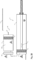
- FIG. 1 illustrated embodiment of a non-inventive coating agent supply device described, which can be arranged for example on a robot arm of a painting robot, as in the already mentioned above document WO 2004/037436 A1 is described for a conventional coating agent supply device, so that the contents of this document with respect to the structure and operation of the painting robot and the other components of the present description is fully attributable.
- the illustrated coating agent supply device has a coating agent metering device 1, which in this exemplary embodiment is a piston metering device.
- the coating agent metering device 1 has a cylinder 2 and a metering piston 3 displaceable in the cylinder 2 in the direction of the arrow, the drive of the metering piston 3 being effected mechanically by a push rod 4, which can be driven, for example, by an electric motor, pneumatically or hydraulically.
- a metering volume 5 which is adjustable by a displacement of the metering piston 3 in the cylinder 2.
- the metering volume 5 with the coating agent contained therein (eg water-based paint) is in operation at a high voltage potential, as symbolized by the high voltage symbol shown.
- the coating agent delivered by the coating agent supply device is therefore also at a high-voltage potential, which contributes to a good application efficiency in the case of an electrostatic coating.
- the metering volume 5 opposite side of the cylinder 2 and the push rod 4, however, is at a ground potential, as symbolized by the grounding sign also shown.
- For electrical isolation of the cylinder 2 and the push rod 4 therefore consist of an electrically insulating material.
- the material of the cylinder 2 and the push rod 4 must On the other hand, however, be sufficiently rigid in order to achieve a sufficient metering accuracy.
- the materials and structural details required for potential separation are, for example, in the document DE 102 33 633 A1 so that the contents of this document are fully attributable to the structure and operation of the coating agent metering device 1 of the present specification.
- a coating agent storage container 6 which consists essentially of a cylinder 7 and a displaceable in the cylinder 7 accumulator piston 8, wherein the accumulator piston 8 is pneumatically driven via a compressed air line 9 and thus an adjustable storage volume 10 in the cylinder 7 includes.
- the entire coating agent storage container 6 is in this case at a ground potential, as symbolized by the grounding symbol.
- the supply of the coating agent storage container 6 is effected by a coating agent supply line 11, which opens into the storage volume 10 and emanates, for example, from a conventional color changer or a loop.
- the withdrawn volume flow also depends on the viscosity of the removed coating agent.
- a low viscosity of the coating agent leads to a relatively large volume flow from the loop.
- a high viscosity of the coating agent leads to a correspondingly low volume flow during removal.
- the viscosity of the coating agent is therefore preferably taken into account, so that the filling of the coating agent storage container 6 is always independent of the viscosity of the coating agent with a constant low flow rate.
- the filling of the coating agent storage container 6 is preferably carried out until the accumulator piston 8 abuts a predetermined stop, whereby the maintenance of a defined filling quantity is ensured.
- the pneumatic backpressure on the accumulator piston 8 is set at the beginning of a removal to a predetermined value and then not regulated.
- the back pressure is then not regulated, but increases with increasing filling of the coating agent storage container 6 accordingly, so that the back pressure is a measure of the degree of filling of the coating agent storage container 6.
- the back pressure is continuously measured.
- the filling of the coating agent storage container 6 is then terminated. At a defined initial volume flow at the beginning of the filling of the coating agent storage container 6 is filled in this way with a defined amount of the coating agent.
- the coating agent storage container 6 From the storage volume 10 of the coating agent storage container 6 further branches off an insulation tube 12, which opens into the metering volume 5 of the coating agent metering 1, the insulation tube 12 in the deflated and cleaned state, the coating agent storage container 6 with respect to the coating agent metering device 1 electrically insulated , which in itself from the already mentioned document WO 2004/037436 A1 is known, so that its content in terms of the structure and operation of the insulating tube 12 of the present description is fully attributable.
- the insulation tube 12 has a larger line cross-section than the coating supply line 11, so that the coating agent metering device 1 can be filled as quickly as possible from the coating agent storage container 6, as will be described in detail.
- the smaller line cross section of the coating agent supply line 11 is harmless, since the filling of the coating agent storage container 6 takes place during painting, so that sufficient time is available for the filling of the coating agent storage container 6.
- the lower cost of the smaller cross-section of the coating agent supply line 11 is advantageous since smaller lines can be used.
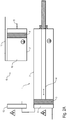
- FIGS. 2A and 2 B show an alternative embodiment of a coating agent supply device according to the invention, which is largely similar to that described above and in FIG. 1 corresponds to the embodiment shown, so that to avoid repetition of the above description FIG. 1 is referenced.
- a special feature of this exemplary embodiment is that the coating agent storage container 6 in this case is not permanently connected to the coating agent metering device 1 via the insulation tube 12. Instead, the coating agent storage container 6 is movable between two positions, which in the FIGS. 2A and 2 B are shown.
- FIG. 2A shown position of the coating agent storage container 6 is connected to the coating agent supply line 11, but separated from the coating agent metering device 1 and is then at an electrical ground potential. In this position, the filling of the coating agent storage container 6 takes place via the coating agent supply line 11.
- the coating agent storage container 6 is connected via a docking interface 13 with the coating agent metering device 1, but separated from the coating agent supply line 11 and is then at the same high-voltage potential as the coating agent metering device 1. In this position, the transfer of the coating agent from the coating agent storage container 6 takes place in the coating agent metering device 1.
- the coating agent storage container 6 is first filled with the new coating agent via the coating agent supply line 11, the coating agent storage container 6 being separated from the docking interface 13, as in FIG. 2A is shown. During this filling of the coating agent storage container 6, the coating agent metering device 1 can continue to meter the old coating agent, so that no filling of the coating agent storage container 6 is required to interrupt the painting process and therefore sufficient time is available for the filling.
- the coating agent storage container 6 After filling of the coating agent storage container 6, the coating agent storage container 6 is then connected after further intermediate steps with the docking interface 13, which in FIG. 2B is shown. After the connection with the docking interface 13 has been established, the new coating agent contained in the storage volume 7 can then be transferred into the metering volume 5 of the coating agent metering device 1.
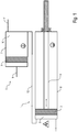
- FIG. 3 shows a simplified representation of a painting robot 21 with a coating agent supply device according to the invention, which largely coincides with the coating agent supply devices described above, so reference is made to avoid repetition of the above description.
- the coating agent metering device 1 is embodied here as a piston dispenser and integrated into an atomizer 22, which is mounted on a hand axis 23 and is guided by a highly mobile robot arm 24.
- the coating agent storage container 6 is arranged stationarily outside the painting robot 21 and can be connected to the coating agent metering device 1 via the docking interface 13.
- the painting robot 21 moves the atomizer 22 so that the docking interface 13 docks onto the coating agent storage container 6, whereupon the coating agent metering device 1 can be filled from the coating agent storage container 6.
- the drawing shows an alternative variant in which the dashed line coating agent metering 1 is integrated into the robot arm 24.
Landscapes
- Electrostatic Spraying Apparatus (AREA)
- Spray Control Apparatus (AREA)
- Application Of Or Painting With Fluid Materials (AREA)
Description
Die Erfindung betrifft eine Beschichtungsmittel-Versorgungseinrichtung, insbesondere für eine Lackieranlage, sowie ein zugehöriges Betriebsverfahren gemäß dem Oberbegriff der nebengeordneten Ansprüche.The invention relates to a coating agent supply device, in particular for a paint shop, and an associated operating method according to the preamble of the independent claims.
Aus
Nachteilig an diesem bekannten Lackierroboter ist zum einen die relativ lange Farbwechseldauer, was insbesondere bei häufigen Farbwechseln zu einer Verlangsamung der Lackierprozesse führt.A disadvantage of this known painting robot, on the one hand, the relatively long color change time, which leads in particular to frequent color changes to a slowdown of the painting.
Zum anderen muss der Kolbendosierer auch ohne einen Farbwechsel wieder befüllt werden, wenn das gesamte Füllungsvolumen des Kolbendosierers von dem Rotationszerstäuber appliziert worden ist. Die Wiederbefüllung des Kolbendosierers durch den Farbwechsler ist hierbei jedoch ebenfalls relativ zeitaufwändig, was die Lackierprozesse verlangsamt.On the other hand, the piston dispenser must be refilled even without a color change when the entire filling volume of the piston dispenser has been applied by the rotary atomizer. However, the refilling of the piston dispenser by the color changer is also relatively time-consuming, which slows down the painting process.
Aus
Weiterhin ist aus
Aus
Weitere Beschichtungseinrichtungen sind bekannt aus
Aus
Schließlich offenbaren
Der Erfindung liegt deshalb die Aufgabe zugrunde, die bekannte Beschichtungsmittel-Versorgungseinrichtung entsprechend zu verbessern.The invention is therefore based on the object to improve the known coating agent supply device accordingly.
Diese Aufgabe wird durch eine Beschichtungsmittel-Versorgungseinrichtung und durch ein zugehöriges Betriebsverfahren gemäß den nebengeordneten Ansprüchen gelöst.This object is achieved by a coating agent supply device and by an associated operating method according to the independent claims.
Die Erfindung umfasst die allgemeine technische Lehre, den Beschichtungsmittel-Dosierer (z.B. einen Kolbendosierer) nicht direkt von dem Farbwechsler zu befüllen, sondern indirekt über einen dazwischen befindlichen Beschichtungsmittel-Speicherbehälter. Dies bietet die Möglichkeit, dass der Beschichtungsmittel-Speicherbehälter bereits während des Lackierens mit Beschichtungsmittel befüllt wird und nicht erst in den Farbwechselzeiten, was zu einer Reduzierung der Farbwechselzeiten beiträgt. Das Umfüllen von dem Beschichtungsmittel-Speicherbehälter in den Beschichtungsmittel-Dosierer kann aufgrund der kurzen und direkten Verbindung mit sehr großen Volumenstrom erfolgen. Die kontinuierliche Befüllung des Beschichtungsmittel-Speicherbehälters während des Lackierens bietet auch den Vorteil, dass aufgrund der zur Verfügung stehenden Zeit für die Befüllung relativ kleine Lackvolumenströme in den Versorgungsleitungen (z.B. Farb-Ringleitungen und Sonder-Farbversorgung) ausreichen, so dass die zugehörigen Leitungen einen kleineren Leitungsquerschnitt aufweisen können, wodurch die Installations-Aufwendungen gesenkt werden.The invention includes the general technical teaching not to fill the coating agent metering device (e.g., a piston dispenser) directly from the color changer, but indirectly via a coating agent storage container therebetween. This offers the possibility that the coating agent storage container is already filled during coating with coating material and not only in the color change times, which contributes to a reduction of the color change times. The transfer from the coating agent storage container into the coating agent metering device can be done due to the short and direct connection with very large volume flow. The continuous filling of the coating agent storage container during painting also offers the advantage that due to the time available for filling relatively small paint volume flows in the supply lines (eg color ring lines and special paint supply) sufficient so that the associated lines a smaller Can have line cross-section, whereby the installation costs are reduced.
Der im Rahmen der Erfindung verwendete Begriff eines Beschichtungsmittel-Dosierers bzw. Dosierers bezeichnet vorzugsweise eine Einrichtung, mit der während der Beschichtung die dem Applikationsgerät zuzuführende Beschichtungsmittelmenge (Momentandurchfluss) bedarfsabhängig, etwa in Abhängigkeit von dem jeweiligen Werkstückbereich und sonstigen Parametern geändert werden kann, wie z.B. in
Erfindungsgemäß liegt der Beschichtungsmittel-Dosierer hierbei zum Lackieren auf einem Hochspannungspotential, während der Beschichtungsmittel-Speicherbehälter auf einem erdnahen Potential (vorzugsweise Massepotential) liegt, wobei der Beschichtungsmittel-Speicherbehälter über eine Isolierstrecke mit dem Beschichtungsmittel-Dosierer verbunden ist, um den auf Hochspannungspotential liegenden Beschichtungsmittel-Dosierer gegenüber dem geerdeten Beschichtungsmittel-Speicherbehälter zu isolieren. Die elektrischen Potentiale des Beschichtungsmittel-Dosierers und des Beschichtungsmittel-Speicherbehälters sind jedoch vorzugsweise schaltbar, so dass der Beschichtungsmittel-Dosierer nur zum Lackieren auf Hochspannungspotential gebracht wird, wohingegen die Hochspannung zum Befüllen des Beschichtungsmittel-Dosierers abgeschaltet werden kann.According to the invention, the coating agent dosing device here is for painting at a high voltage potential, while the coating agent storage tank is at a near-ground potential (preferably ground potential), wherein the coating agent storage tank is connected via an insulating with the coating agent dosing to the coating material lying at high voltage potential Doser isolate against the grounded coating agent storage tank. However, the electrical potentials of the coating agent metering agent and the coating agent storage container are preferably switchable, so that the coating agent metering device is brought to high voltage potential only for painting, whereas the high voltage for filling the coating agent metering device can be switched off.
Der Beschichtungsmittel-Speicherbehälter kann auch direkt mit der Beschichtungsmittel-Zuleitung verbunden sein.The coating agent storage container may also be connected directly to the coating agent supply line.
Die Andock-Schnittstelle für die Verbindung des Beschichtungsmittel-Dosierers mit dem Beschichtungsmittel-Speicherbehälter kann hierbei in dem Lackierroboter angebracht sein, beispielsweise in einem Roboterarm, so dass die Andock-Schnittstelle mit dem Lackierroboter beweglich ist. Zusätzlich zu der Andock-Schnittstelle kann hierbei auch ein Farbwechsler in dem Lackierroboter angeordnet sein.The docking interface for the connection of the coating agent metering device with the coating agent storage container can in this case be mounted in the painting robot, for example in a robot arm, so that the docking interface with the painting robot is movable. additionally To the docking interface, a color changer can also be arranged in the painting robot.
Es besteht jedoch alternativ auch die Möglichkeit, dass die Andock-Schnittstelle außerhalb des Lackierroboters stationär angeordnet ist. Bei dieser Anordnung der Andock-Schnittstelle besteht die Möglichkeit, dass die Andock-Schnittstelle mit dem Lackierroboter mitfährt, indem die Andock-Schnittstelle beispielsweise auf der Achse 7 des Lackierroboters angebracht ist.However, there is also the alternative possibility that the docking interface is arranged stationary outside the painting robot. In this arrangement, the docking interface, there is the possibility that the docking interface mitfährt with the painting robot by the docking interface is mounted for example on the
In dem bevorzugten Ausführungsbeispiel der Erfindung weist der Beschichtungsmittel-Speicherbehälter ein einstellbares Speichervolumen auf, wobei das Speichervolumen beispielsweise durch einen druckluftbetätigten Kolben einstellbar ist. Dies bietet bei einem Farbwechsel die Möglichkeit, dass das in dem Beschichtungsmittel-Speicherbehälter nach der Befüllung des Beschichtungsmittel-Dosierers verbliebene neue Beschichtungsmittel wieder aus dem Beschichtungsmittel-Speicherbehälter zurück in die Beschichtungsmittel-Zuleitung gedrückt wird, was auch als "Reflow" bezeichnet wird. Zum einen wird durch diesen "Reflow" der Beschichtungsmittelverbrauch gesenkt, da das in dem Beschichtungsmittel-Speicherbehälter nach der Befüllung des Beschichtungsmittel-Dosierers verbliebene neue Beschichtungsmittel weiter genutzt werden kann. Zum anderen wird dadurch die Reinigung des Beschichtungsmittel-Speicherbehälters erleichtert, so dass weniger Spülmittel benötigt wird.In the preferred embodiment of the invention, the coating agent storage container on an adjustable storage volume, wherein the storage volume is adjustable for example by a compressed air-operated piston. In the case of a color change, this offers the possibility that the new coating agent remaining in the coating agent storage container after the filling of the coating agent metering device is pushed back out of the coating agent storage container back into the coating agent supply line, which is also referred to as "reflow". On the one hand, this "reflow" reduces the coating agent consumption, since the new coating agent remaining in the coating agent storage container after the filling of the coating agent metering device can continue to be used. On the other hand, the cleaning of the coating agent storage container is facilitated thereby, so that less detergent is needed.
Vorzugsweise handelt es sich bei dem Beschichtungsmittel-Dosierer um einen Kolbendosierer, wie er beispielsweise in der eingangs erwähnten Druckschrift
Bei dem Beschichtungsmittel-Speicherbehälter handelt es sich vorzugsweise um einen Zylinder mit einem Speicherkolben, der in dem Zylinder verschiebbar angeordnet ist, wobei der Antrieb des Speicherkolbens beispielsweise elektromotorisch, hydraulisch oder pneumatisch erfolgen kann. Die Stellung des Speicherkolbens bestimmt dann das Speichervolumen des Beschichtungsmittel-Speicherbehälters.The coating agent storage container is preferably a cylinder with a storage piston which is displaceably arranged in the cylinder, wherein the drive of the storage piston can be carried out, for example, by an electric motor, hydraulically or pneumatically. The position of the storage piston then determines the storage volume of the coating agent storage container.
Die Erfindung eignet sich besonders vorteilhaft zur Applikation von Wasserlack, jedoch ist die Erfindung hinsichtlich des zu applizierenden Beschichtungsmittels nicht auf Wasserlack beschränkt, sondern grundsätzlich auch mit anderen Beschichtungsmitteltypen realisierbar.The invention is particularly advantageous for the application of water-based paint, but the invention is not limited to water-based paint with respect to the coating agent to be applied, but in principle also feasible with other types of coating agents.
Ferner umfasst die Erfindung nicht nur die vorstehend beschriebene erfindungsgemäße Beschichtungsmittel-Versorgungseinrichtung, sondern auch einen kompletten Lackierroboter mit einer derartigen Beschichtungsmittel-Versorgungseinrichtung. In diesem Fall sind der Beschichtungsmittel-Dosierer und der Beschichtungsmittel-Speicherbehälter vorzugsweise in oder auf einem oder mehreren Roboterarmen des Lackierroboters angeordnet.Furthermore, the invention comprises not only the coating agent supply device according to the invention described above, but also a complete painting robot with such a coating agent supply device. In this case, the coating agent metering device and the coating agent storage container are preferably arranged in or on one or more robot arms of the painting robot.
Schließlich umfasst die Erfindung auch ein entsprechendes Betriebsverfahren, wie sich bereits aus der vorliegenden Beschreibung der erfindungsgemäßen Beschichtungsmittel-Versorgungseinrichtung ergibt.Finally, the invention also encompasses a corresponding operating method, as already apparent from the present description of the coating agent supply device according to the invention.
Andere vorteilhafte Weiterbildungen der Erfindung sind in den Unteransprüchen gekennzeichnet oder werden nachstehend zusammen mit der Beschreibung der bevorzugten Ausführungsbeispiele der Erfindung anhand der Figuren näher erläutert. Es zeigen:
Figur 1- eine vereinfachte Darstellung einer nicht erfindungsgemäßen Beschichtungsmittel-Versorgungseinrichtung für einen Lackierroboter, wobei ein Beschichtungsmittel-Speicherbehälter über eine Isolierstrecke mit einem Beschichtungsmittel-Dosierer verbunden ist,
- Figuren 2A, 2B
- ein alternatives Ausführungsbeispiel einer erfindungsgemäßen Beschichtungsmittel-Versorgungseinrichtung, bei dem der Beschichtungsmittel-Speicherbehälter zwischen einem Massepotential und einem Hochspannungspotential verfahrbar ist und über eine Andock-Schnittstelle vorübergehend mit dem Beschichtungsmittel-Dosierer verbunden wird,
- Figur 3
- eine vereinfachte Darstellung eines Lackierroboters mit einem beweglich geführten Beschichtungsmittel-Dosierer und einem ortfest montierten Beschichtungsmittel-Speicherbehälter.
- FIG. 1
- a simplified representation of a non-inventive coating agent supply device for a painting robot, wherein a coating agent storage container is connected via an insulating section with a coating agent dosing,
- FIGS. 2A, 2B
- an alternative embodiment of a coating agent supply device according to the invention, in which the coating agent storage container between a ground potential and a high voltage potential is movable and is connected via a docking interface temporarily with the coating agent dosing,
- FIG. 3
- a simplified representation of a painting robot with a movably guided coating agent dosing and a stationary mounted coating agent storage tank.
Im Folgenden wird zunächst das in
Die dargestellte Beschichtungsmittel-Versorgungseinrichtung weist einen Beschichtungsmittel-Dosierer 1 auf, wobei es sich in diesem Ausführungsbeispiel um einen Kolbendosierer handelt. Der Beschichtungsmittel-Dosierer 1 weist einen Zylinder 2 und einen in dem Zylinder 2 in Pfeilrichtung verschiebbaren Dosierkolben 3 auf, wobei der Antrieb des Dosierkolbens 3 mechanisch durch eine Schubstange 4 erfolgt, die beispielsweise elektromotorisch, pneumatisch oder hydraulisch angetrieben werden kann. In dem Zylinder 2 des Beschichtungsmittel-Dosierers 1 befindet sich an der Vorderseite des Dosierkolbens 3 ein Dosiervolumen 5, das durch eine Verschiebung des Dosierkolbens 3 in dem Zylinder 2 einstellbar ist. Das Dosiervolumen 5 mit dem darin befindlichen Beschichtungsmittel (z.B. Wasserlack) befindet sich im Betrieb auf einem Hochspannungspotential, wie durch das dargestellte Hochspannungszeichen symbolisiert wird. Das von der Beschichtungsmittel-Versorgungseinrichtung abgegebene Beschichtungsmittel liegt deshalb ebenfalls auf einem Hochspannungspotential, was bei einer elektrostatischen Lackierung zu einem guten Auftragswirkungsgrad beiträgt. Die dem Dosiervolumen 5 gegenüberliegende Seite des Zylinders 2 und der Schubstange 4 liegt dagegen auf einem Massepotential, wie durch das ebenfalls dargestellte Erdungszeichen symbolisiert ist. Zur elektrischen Potentialtrennung bestehen der Zylinder 2 und die Schubstange 4 deshalb aus einem elektrisch isolierenden Material. Das Material des Zylinders 2 und der Schubstange 4 muss jedoch andererseits hinreichend starr sein, um eine ausreichende Dosiergenauigkeit zu erreichen. Die zur Potentialtrennung erforderlichen Materialien und konstruktiven Einzelheiten sind beispielsweise in der Druckschrift
Weiterhin weist die Beschichtungsmittel-Versorgungseinrichtung in diesem Ausführungsbeispiel einen Beschichtungsmittel-Speicherbehälter 6 auf, der im Wesentlichen aus einem Zylinder 7 und einem in dem Zylinder 7 verschiebbaren Speicherkolben 8 besteht, wobei der Speicherkolben 8 über eine Druckluftleitung 9 pneumatisch angetrieben wird und somit ein einstellbares Speichervolumen 10 in dem Zylinder 7 einschließt. Der gesamte Beschichtungsmittel-Speicherbehälter 6 befindet sich hierbei auf einem Massepotential, wie durch das Erdungszeichen symbolisch dargestellt wird.Furthermore, the coating agent supply device in this embodiment, a coating
Die Versorgung des Beschichtungsmittel-Speicherbehälters 6 erfolgt durch eine Beschichtungsmittel-Zuleitung 11, die in das Speichervolumen 10 mündet und beispielsweise von einem herkömmlichen Farbwechsler oder einer Ringleitung ausgeht.The supply of the coating
Bei der Befüllung des Beschichtungsmittel-Speicherbehälters 6 ist es wünschenswert, dass aus der Ringleitung ein konstant niedriger Volumenstrom entnommen wird. Dies ist sinnvoll, weil eine Entnahme mit einem plötzlich ansteigenden Volumenstrom zu einem Druckabfall in der Ringleitung führen würde, wodurch druckempfindliche Entnahmestationen (z.B. Handspritzer) an der Ringleitung gestört würden. Zur Vermeidung derartiger Druckeinbrüche in der Ringleitung kann der Speicherkolben 8 über die Druckluftleitung 9 mit einem Gegendruck beaufschlagt werden, der so eingestellt wird, dass die Entnahme aus der Ringleitung mit dem gewünschten Volumenstrom erfolgt.When filling the coating
Hierbei ist zu berücksichtigen, dass der entnommene Volumenstrom auch von der Viskosität des entnommenen Beschichtungsmittels abhängt. So führt eine geringe Viskosität des Beschichtungsmittels zu einem relativ großen Volumenstrom aus der Ringleitung. Eine hohe Viskosität des Beschichtungsmittels führt dagegen zu einem entsprechend geringen Volumenstrom bei der Entnahme. Bei der Einstellung des pneumatischen Gegendrucks auf den Speicherkolben 8 wird deshalb vorzugsweise die Viskosität des Beschichtungsmittels berücksichtigt, so dass die Befüllung des Beschichtungsmittel-Speicherbehälters 6 unabhängig von der Viskosität des Beschichtungsmittels stets mit einem konstant niedrigen Volumenstrom erfolgt. Die Befüllung des Beschichtungsmittel-Speicherbehälters 6 erfolgt hierbei vorzugsweise so lange, bis der Speicherkolben 8 an einen vorgegeben Anschlag stößt, wodurch die Einhaltung einer definierten Füllmenge sichergestellt wird.It should be noted that the withdrawn volume flow also depends on the viscosity of the removed coating agent. Thus, a low viscosity of the coating agent leads to a relatively large volume flow from the loop. On the other hand, a high viscosity of the coating agent leads to a correspondingly low volume flow during removal. When setting the pneumatic back pressure on the
Alternativ zu der vorstehend beschriebenen Gegendruckregelung besteht die Möglichkeit, dass der pneumatische Gegendruck auf den Speicherkolben 8 zu Beginn einer Entnahme auf einen vorgegebenen Wert eingestellt und anschließend nicht geregelt wird. Bei der anschließenden Befüllung des Beschichtungs-Speicherbehälters 6 wird der Gegendruck dann nicht geregelt, sondern nimmt mit zunehmender Befüllung des Beschichtungsmittel-Speicherbehälters 6 entsprechend zu, so dass der Gegendruck ein Maß für den Füllungsgrad des Beschichtungsmittel-Speicherbehälters 6 ist. Während der Befüllung des Beschichtungsmittel-Speicherbehälters 6 wird deshalb laufend der Gegendruck gemessen. Nach Erreichen eines vorgegebenen Sollwerts für den Gegendruck wird dann die Befüllung des Beschichtungsmittel-Speicherbehälters 6 beendet. Bei einem definierten anfänglichen Volumenstrom zu Beginn der Befüllung wird der Beschichtungsmittel-Speicherbehälter 6 auf diese Weise mit einer definierten Menge des Beschichtungsmittels befüllt.As an alternative to the backpressure control described above, there is the possibility that the pneumatic backpressure on the
Aus dem Speichervolumen 10 des Beschichtungsmittel-Speicherbehälters 6 zweigt weiterhin ein Isolationsschlauch 12 ab, der in das Dosiervolumen 5 des Beschichtungsmittel-Dosierers 1 mündet, wobei der Isolationsschlauch 12 im entleerten und gereinigten Zustand den Beschichtungsmittel-Speicherbehälter 6 gegenüber dem Beschichtungsmittel-Dosierer 1 elektrisch isoliert, was an sich aus der bereits eingangs erwähnten Druckschrift
Der Isolationsschlauch 12 weist jedoch einen größeren Leitungsquerschnitt auf als die Beschichtungszuleitung 11, damit der Beschichtungsmittel-Dosierer 1 möglichst schnell aus dem Beschichtungsmittel-Speicherbehälter 6 befüllt werden kann, wie noch detailliert beschrieben wird. Der geringere Leitungsquerschnitt der Beschichtungsmittelzuleitung 11 ist dagegen unschädlich, da die Befüllung des Beschichtungsmittel-Speicherbehälters 6 während des Lackierens erfolgt, so dass für die Befüllung des Beschichtungsmittel-Speicherbehälters 6 genügend Zeit zur Verfügung steht. Vorteilhaft an dem geringeren Leitungsquerschnitt der Beschichtungsmittelzuleitung 11 sind dagegen die geringeren Kosten, da kleinere Leitungen verwendet werden können.However, the
Zu diesem Ausführungsbeispiel und zu den folgenden Ausführungsbeispielen ist ferner zu erwähnen, dass vor und hinter dem Beschichtungsmittel-Speicherbehälter 6 und dem Beschichtungsmittel-Dosierer 1 weitere Bauelemente angeordnet sein können, wie beispielsweise steuerbare Ventile, die jedoch in der Zeichnung zur Vereinfachung nicht dargestellt sind.To this embodiment and to the following embodiments is further to mention that before and behind the coating
Die
Eine Besonderheit dieses Ausführungsbeispiels besteht darin, dass der Beschichtungsmittel-Speicherbehälter 6 hierbei nicht permanent über den Isolationsschlauch 12 mit dem Beschichtungsmittel-Dosierer 1 verbunden ist. Stattdessen ist der Beschichtungsmittel-Speicherbehälter 6 zwischen zwei Stellungen verfahrbar, die in den
In der in
In der in
Für einen Farbwechsel wird hierbei also zunächst der Beschichtungsmittel-Speicherbehälter 6 über die Beschichtungsmittel-Zuleitung 11 mit dem neuen Beschichtungsmittel befüllt, wobei der Beschichtungsmittel-Speicherbehälter 6 von der Andock-Schnittstelle 13 abgetrennt ist, wie in
Nach der Befüllung des Beschichtungsmittel-Speicherbehälters 6 wird der Beschichtungsmittel-Speicherbehälter 6 dann nach weiteren Zwischenschritten mit der Andockschnittstelle 13 verbunden, was in
Der Beschichtungsmittel-Dosierer 1 ist hierbei als Kolbendosierer ausgeführt und in einen Zerstäuber 22 integriert, der an einer Handachse 23 montiert ist und von einem hochbeweglichen Roboterarm 24 geführt wird.The coating
Der Beschichtungsmittel-Speicherbehälter 6 ist dagegen außerhalb des Lackierroboters 21 ortsfest angeordnet und kann über die Andock-Schnittstelle 13 mit dem Beschichtungsmittel-Dosierer 1 verbunden werden. Hierzu bewegt der Lackierroboter 21 den Zerstäuber 22 so, dass die Andock-Schnittstelle 13 an dem Beschichtungsmittel-Speicherbehälter 6 andockt, woraufhin der Beschichtungsmittel-Dosierer 1 aus dem Beschichtungsmittel-Speicherbehälter 6 befüllt werden kann.By contrast, the coating
Weiterhin zeigt die Zeichnung eine alternative Variante, bei der der gestrichelt gezeichnete Beschichtungsmittel-Dosierer 1 in den Roboterarm 24 integriert ist.Furthermore, the drawing shows an alternative variant in which the dashed line
Claims (8)
- Coating agent supply device for a painting plant, comprisinga) an atomizer (22),b) a painting robot (21) for guiding the atomizer (22),c) a coating agent doser (1), wherein the coating agent doser (1)c1) doses a coating agent to be applied to the atomizer (22),c2) is a piston dosing device comprising a cylinder (2) and a dosing piston (3) slidable in the cylinder (2), andc3) lies at least temporarily on a high-voltage potential,c4) is arranged in the atomizer (22) guided by the painting robot (21) and moves with the painting robot (21),d) a ring circuit (38), ande) a docking interface (13),
characterised in thatf) the coating agent supply device comprises a coating agent storage container (6) for temporarily receiving the coating agent and for supplying the coating agent doser (1) with the coating agent, wherein the coating agent storage container (6)f1) is arranged upstream of the coating agent doser (1) and is connected to the coating agent doser (1) on the output side,f2) is stationary andf3) is on a potential close to earth, andf4) is filled from the ring circuit (38), andg) in that the coating agent doser (1) can be connected to the coating agent storage container (6) in a separable manner via the dock interface (13). - Coating agent supply device according to claim 1, characterized in thata) the coating agent storage container (6) has an adjustable storage volume (10), and/orb) the storage volume (10) of the coating agent storage tank (6) is adjustable by a piston (8), and/orc) the piston (8) of the coating agent storage tank (6) is driven by an electric motor, compressed air or hydraulically.
- Painting plant with a coating agent supply device according to one of the previous claims.
- A method of operation for a coating agent supply device according to one of Claims 1 to 2, comprising the following steps:a) Dosing of a coating agent by a coating agent dosage device (1) to an atomizer (22),b) supplying the coating agent doser (1) with the coating agent via a coating agent storage container (6), which is arranged upstream of the coating agent doser (1) and is connected to the coating agent doser (1) on the output side,c) filling the coating agent storage tank with the coating agent via a coating agent feed line in the form of a ring line (38), the coating agent storage tank being firmly connected to the coating agent feed line,d) Electrical grounding of the atomizer (22) after an application process,e) docking the earthed atomizer (22) with the coating agent doser to the coating agent storage container by means of a painting robot, wherein the painting robot guides the atomizer (22) in a highly mobile manner,f) Transferring the coating agent from the coating agent storage tank to the coating agent doser when the coating agent doser is docked to the coating agent storage tank,g) undocking of the atomizer (22) with the coating agent doser from the coating agent storage tank after the transfer,h) Application of the coating agent.
- Operating method according to claim 4, characterized by the following steps when changing the colour from an old coating agent to a new coating agent:a) Filling of the coating agent storage tank (6) with the new coating agent from a coating agent feed line (11) during dosing of the old coating agent by the coating agent doser (1),b) Stopping the dosing of the old coating agent by the coating agent doser (1),c) Filling the coating agent doser (1) with the new coating agent from the coating agent storage container (6),d) Start of dosing of the new coating agent by the coating agent doser (1).
- Operating procedures according to claim 5,
characterized by the following steps:- Emptying of the remaining old coating agent from the coating agent doser (1) after completion of dosing of the old coating agent and before filling the coating agent doser (1) with the new coating agent, and/or- rinsing the coating agent doser (1) with a rinsing agent after emptying the old coating agent from the coating agent doser (1) and prior to filling the coating agent doser (1) with the new coating agent, and/or- returning the remaining new coating agent remaining in the coating agent storage tank (6) after filling the coating agent doser (1) into the coating agent feed line (11), and/or- rinsing the coating agent storage tank (6) with a rinsing liquid after the new coating agent remaining therein has been returned to the coating agent feed line (11). - Operating procedure in accordance with one of Claims 4 to 6, characterised by the following step:
Applying a high-voltage potential to the coating agent doser and the atomizer (22). - Operating method according to one of Claims 4 to 7, characterized in thata) the coating agent storage tank (6) is filled with a smaller coating agent stream than the dosing of the coating agent by the coating agent doser (1) and/or as the filling of the coating agent doser (1), and/orb) the coating agent storage container (6) has a storage volume (10) which can be adjusted by means of a sliding piston (8), the piston (8) being pneumatically pressurized with a counter-pressure which is dependent on the viscosity of the coating agent, and/orc) the counter-pressure is adjusted in such a way that the volumetric flow when filling the coating agent reservoir (6) is independent of the viscosity of the coating agent.
Applications Claiming Priority (3)
| Application Number | Priority Date | Filing Date | Title |
|---|---|---|---|
| DE102005048223A DE102005048223A1 (en) | 2005-10-07 | 2005-10-07 | Coating supply device for object e.g. automobile body parts has coating reservoir used for holding and supplying coating to coating meter, and located upstream from coating meter and connected on output side to coating meter |
| DE102005060959.7A DE102005060959B4 (en) | 2005-10-07 | 2005-12-20 | Coating agent supply device and associated operating procedure |
| EP06021045.7A EP1772194B1 (en) | 2005-10-07 | 2006-10-06 | Supply device for a coating agent and appropriate operating method |
Related Parent Applications (2)
| Application Number | Title | Priority Date | Filing Date |
|---|---|---|---|
| EP06021045.7A Division-Into EP1772194B1 (en) | 2005-10-07 | 2006-10-06 | Supply device for a coating agent and appropriate operating method |
| EP06021045.7A Division EP1772194B1 (en) | 2005-10-07 | 2006-10-06 | Supply device for a coating agent and appropriate operating method |
Publications (2)
| Publication Number | Publication Date |
|---|---|
| EP2810719A1 EP2810719A1 (en) | 2014-12-10 |
| EP2810719B1 true EP2810719B1 (en) | 2018-06-20 |
Family
ID=37564099
Family Applications (2)
| Application Number | Title | Priority Date | Filing Date |
|---|---|---|---|
| EP14002527.1A Revoked EP2810719B1 (en) | 2005-10-07 | 2006-10-06 | Supply device for a coating agent and appropriate operating method |
| EP06021045.7A Active EP1772194B1 (en) | 2005-10-07 | 2006-10-06 | Supply device for a coating agent and appropriate operating method |
Family Applications After (1)
| Application Number | Title | Priority Date | Filing Date |
|---|---|---|---|
| EP06021045.7A Active EP1772194B1 (en) | 2005-10-07 | 2006-10-06 | Supply device for a coating agent and appropriate operating method |
Country Status (4)
| Country | Link |
|---|---|
| EP (2) | EP2810719B1 (en) |
| DE (1) | DE202006021283U1 (en) |
| ES (2) | ES2685244T3 (en) |
| HU (1) | HUE043560T2 (en) |
Families Citing this family (4)
| Publication number | Priority date | Publication date | Assignee | Title |
|---|---|---|---|---|
| US8020784B2 (en) | 2005-10-07 | 2011-09-20 | Durr Systems Inc. | Coating material supply installation and associated operating procedure |
| WO2008071273A2 (en) | 2006-12-12 | 2008-06-19 | Dürr Systems GmbH | Coating apparatus comprising a metering device |
| DE102007029195A1 (en) | 2007-06-25 | 2009-02-19 | Dürr Systems GmbH | Coating device for serially coating workpieces with different shades comprises a separate color changer containing color valves to which are connected color lines for the coating material |
| DE102020104325A1 (en) | 2020-02-19 | 2021-08-19 | Dürr Systems Ag | Rinsing device for connecting to a main application agent channel of an application agent changer |
Citations (26)
| Publication number | Priority date | Publication date | Assignee | Title |
|---|---|---|---|---|
| US4313475A (en) | 1980-06-26 | 1982-02-02 | The Gyromat Corporation | Voltage block system for electrostatic coating with conductive materials |
| WO1987005832A1 (en) | 1986-03-24 | 1987-10-08 | Leif Tilly | A method for supplying an electrically conductive, floating medium and a device for performing the method |
| EP0274322A1 (en) * | 1987-01-02 | 1988-07-13 | Sames S.A. | Installation for paint spraying, particularly an installation for the electrostatic spraying of water paint |
| EP0428435A1 (en) | 1989-11-14 | 1991-05-22 | Sames S.A. | Installation for electrostatically applying a conductive coating product |
| FR2662620A1 (en) | 1990-05-31 | 1991-12-06 | Sames Sa | PROJECTION INSTALLATION OF PULVERIZED COATING PRODUCT WITH DEBIT CONTROL. |
| EP0467626A1 (en) | 1990-07-18 | 1992-01-22 | Nordson Corporation | Improvements in and relating to electrostatically isolating and pumping conductive coating materials |
| EP0487378A1 (en) | 1990-11-20 | 1992-05-27 | Sames S.A. | Electrostatic painting installation for a conductive liquid coating product |
| US5197676A (en) | 1990-07-18 | 1993-03-30 | Nordson Corporation | Apparatus for dispensing conductive coating materials |
| WO1993006936A1 (en) | 1991-10-04 | 1993-04-15 | Gmfanuc Robotics Corporation | Method and system for fluid transfer and non-contact sensor for use therein |
| WO1994022590A1 (en) | 1993-04-01 | 1994-10-13 | Sames S.A. | Machine for spraying a coating material |
| GB2282085A (en) | 1993-08-18 | 1995-03-29 | John Stephen Griffiths | Paint supply apparatus |
| EP0693319A1 (en) | 1994-07-13 | 1996-01-24 | Sames S.A. | Spraying device comprising a container for a coating material and method for cleaning and filling such a container |
| FR2777482A1 (en) * | 1998-04-15 | 1999-10-22 | Sames Sa | METHOD AND INSTALLATION FOR SPRAYING COATING PRODUCTS BY MEANS OF AN AUTOMATON EQUIPPED WITH A TANK |
| WO2001015814A1 (en) | 1999-08-30 | 2001-03-08 | Sames Technologies | Method and station for changing product in a installation spraying coating product |
| WO2001015816A1 (en) | 1999-08-30 | 2001-03-08 | Sames Technologies | Device for spraying a coating product comprising at least a sprayer and a piston reservoir |
| EP1108474A2 (en) | 1999-12-18 | 2001-06-20 | INLAC Industrie-Lackieranlagen GmbH | Painting installation |
| FR2808709A1 (en) | 2000-05-15 | 2001-11-16 | Eisenmann France Sarl | METHOD FOR RECOVERING A COATING FLUID, SUCH AS A PAINT, CONTAINED IN A PLANT |
| FR2811917A1 (en) | 2000-07-24 | 2002-01-25 | Sames Sa | Robot painting system for car manufacture includes storage zone for cleaning and refilling two paint heads used alternately by paint robot |
| FR2813538A1 (en) | 2000-09-05 | 2002-03-08 | Eisenmann France Sarl | METHOD AND DEVICE FOR FILLING A PAINT TANK IN AN AUTOMATED PAINT SYSTEM |
| WO2002032586A1 (en) | 2000-10-19 | 2002-04-25 | Sames Technologies | Device and method for feeding sprayers and spraying installation equipped with such a device |
| WO2002092236A2 (en) | 2001-05-16 | 2002-11-21 | Fanuc Robotics North America, Inc. | Voltage block and color change apparatus for waterborne bell applicator |
| EP1314483A2 (en) | 2001-11-27 | 2003-05-28 | Dürr Systems GmbH | Method and system for metered delivery of coating material to a coating apparatus |
| US6612345B1 (en) | 1999-05-06 | 2003-09-02 | Abb K.K. | Cartridge paint-charging method and device therefor |
| DE10233633A1 (en) | 2002-07-24 | 2004-02-12 | Dürr Systems GmbH | Device for dosing or conveying a medium |
| WO2004037436A1 (en) | 2002-10-23 | 2004-05-06 | Fanuc Robotics America, Inc. | Robotic apparatus for painting |
| EP1502656A2 (en) | 2003-07-28 | 2005-02-02 | Dürr Systems GmbH | Method and paint supply system for an electrostatic coating station and coupling system therefore |
Family Cites Families (25)
| Publication number | Priority date | Publication date | Assignee | Title |
|---|---|---|---|---|
| US4020866A (en) * | 1973-12-03 | 1977-05-03 | The Gyromat Corporation | Pressure vessel for voltage block material supply system |
| JPS5895558A (en) | 1981-11-30 | 1983-06-07 | Mazda Motor Corp | Robot for motorcar body coating |
| DE3526958A1 (en) | 1985-07-27 | 1985-12-19 | Daimler-Benz Ag, 7000 Stuttgart | Enamelling robot which can be programmed by the teach-in method |
| DE3644536C1 (en) * | 1986-12-24 | 1987-11-19 | Basf Lacke & Farben | Device for a water-based paint application with high-speed rotary atomizers via direct charging or contact charging |
| DE3713999A1 (en) | 1987-04-27 | 1988-11-10 | Behr Industrieanlagen | METHOD FOR AUTOMATIC SERIAL COATING OF WORKPIECES |
| DE8906341U1 (en) | 1989-05-23 | 1989-07-13 | Sata - Farbspritztechnik GmbH & Co, 7140 Ludwigsburg | Painting robot |
| DE4013940A1 (en) * | 1990-04-30 | 1991-10-31 | Behr Industrieanlagen | METHOD AND SYSTEM FOR SERIES COATING OF WORKPIECES WITH CONDUCTIVE COATING MATERIAL |
| DE4013942A1 (en) * | 1990-04-30 | 1991-10-31 | Behr Industrieanlagen | PLANT FOR SERIES COATING OF WORKPIECES WITH CONDUCTIVE COATING MATERIAL |
| FR2695327B1 (en) | 1992-09-09 | 1995-07-07 | Sames Sa | Device for electrostatic projection of electrically conductive coating product, provided with an insulated reservoir adapted to contain such a product. |
| JP3259075B2 (en) * | 1992-11-18 | 2002-02-18 | 本田技研工業株式会社 | Intermediate storage tank for coating equipment |
| US5364035A (en) * | 1993-12-20 | 1994-11-15 | Graco Inc. | High voltage sealing and isolation via dynamic seals |
| DE19524853C2 (en) | 1994-07-12 | 2000-02-24 | Ransburg Corp | Coating device |
| JP3245040B2 (en) | 1996-02-29 | 2002-01-07 | トリニティ工業株式会社 | Electrostatic coating machine |
| DE19610588B4 (en) | 1996-03-18 | 2010-08-05 | Dürr Systems GmbH | Coating machine with replaceable container |
| JP3513050B2 (en) | 1998-11-13 | 2004-03-31 | トヨタ自動車株式会社 | Painting robot and assembly method of painting robot |
| DE10103067A1 (en) * | 2001-01-24 | 2002-07-25 | Duerr Systems Gmbh | A method for automatically changing the spray head of a paint spraying robotic machine has the multi-axis nozzle and paint reservoir detachable through a connecting interface |
| DE10108010A1 (en) | 2001-02-20 | 2002-08-29 | Duerr Systems Gmbh | Spray device with at least one separation point |
| DE10115463A1 (en) | 2001-03-29 | 2002-10-02 | Duerr Systems Gmbh | Atomizer for a coating system and process for its material supply |
| DE10140216B4 (en) | 2001-08-17 | 2006-02-09 | ITW Oberflächentechnik GmbH & Co. KG | Method and device on a painting device for cleaning a paint delivery line |
| DE10216581B4 (en) | 2002-04-14 | 2006-07-20 | Asis Gmbh | Supply line for coating plants, in particular painting plants |
| DE10304652A1 (en) | 2003-02-05 | 2004-08-19 | Dürr Systems GmbH | robot |
| DE10320147A1 (en) * | 2003-05-06 | 2004-12-09 | Dürr Systems GmbH | Method and supply system for the metered supply of material to a coating device |
| DE10335358A1 (en) | 2003-08-01 | 2005-03-10 | Duerr Systems Gmbh | Coating agents changer |
| DE102004015117A1 (en) * | 2004-03-27 | 2005-10-13 | Daimlerchrysler Ag | Flushing system for cleaning of units with adhering liquid paint has reservoir for used flushing liquid by which used flushing liquid without further processing is partially or completely returned to units for cleaning |
| DE102004016951A1 (en) | 2004-04-06 | 2005-11-10 | Dürr Systems GmbH | Method for conveying a coating material and coating machine |
-
2006
- 2006-10-06 EP EP14002527.1A patent/EP2810719B1/en not_active Revoked
- 2006-10-06 DE DE202006021283.3U patent/DE202006021283U1/en not_active Expired - Lifetime
- 2006-10-06 EP EP06021045.7A patent/EP1772194B1/en active Active
- 2006-10-06 HU HUE06021045A patent/HUE043560T2/en unknown
- 2006-10-06 ES ES14002527.1T patent/ES2685244T3/en active Active
- 2006-10-06 ES ES06021045T patent/ES2717116T3/en active Active
Patent Citations (27)
| Publication number | Priority date | Publication date | Assignee | Title |
|---|---|---|---|---|
| US4313475A (en) | 1980-06-26 | 1982-02-02 | The Gyromat Corporation | Voltage block system for electrostatic coating with conductive materials |
| US4313475B1 (en) | 1980-06-26 | 1994-07-12 | Nordson Corp | Voltage block system for electrostatic coating with conductive materials |
| WO1987005832A1 (en) | 1986-03-24 | 1987-10-08 | Leif Tilly | A method for supplying an electrically conductive, floating medium and a device for performing the method |
| EP0274322A1 (en) * | 1987-01-02 | 1988-07-13 | Sames S.A. | Installation for paint spraying, particularly an installation for the electrostatic spraying of water paint |
| EP0428435A1 (en) | 1989-11-14 | 1991-05-22 | Sames S.A. | Installation for electrostatically applying a conductive coating product |
| FR2662620A1 (en) | 1990-05-31 | 1991-12-06 | Sames Sa | PROJECTION INSTALLATION OF PULVERIZED COATING PRODUCT WITH DEBIT CONTROL. |
| EP0467626A1 (en) | 1990-07-18 | 1992-01-22 | Nordson Corporation | Improvements in and relating to electrostatically isolating and pumping conductive coating materials |
| US5197676A (en) | 1990-07-18 | 1993-03-30 | Nordson Corporation | Apparatus for dispensing conductive coating materials |
| EP0487378A1 (en) | 1990-11-20 | 1992-05-27 | Sames S.A. | Electrostatic painting installation for a conductive liquid coating product |
| WO1993006936A1 (en) | 1991-10-04 | 1993-04-15 | Gmfanuc Robotics Corporation | Method and system for fluid transfer and non-contact sensor for use therein |
| WO1994022590A1 (en) | 1993-04-01 | 1994-10-13 | Sames S.A. | Machine for spraying a coating material |
| GB2282085A (en) | 1993-08-18 | 1995-03-29 | John Stephen Griffiths | Paint supply apparatus |
| EP0693319A1 (en) | 1994-07-13 | 1996-01-24 | Sames S.A. | Spraying device comprising a container for a coating material and method for cleaning and filling such a container |
| FR2777482A1 (en) * | 1998-04-15 | 1999-10-22 | Sames Sa | METHOD AND INSTALLATION FOR SPRAYING COATING PRODUCTS BY MEANS OF AN AUTOMATON EQUIPPED WITH A TANK |
| US6612345B1 (en) | 1999-05-06 | 2003-09-02 | Abb K.K. | Cartridge paint-charging method and device therefor |
| WO2001015814A1 (en) | 1999-08-30 | 2001-03-08 | Sames Technologies | Method and station for changing product in a installation spraying coating product |
| WO2001015816A1 (en) | 1999-08-30 | 2001-03-08 | Sames Technologies | Device for spraying a coating product comprising at least a sprayer and a piston reservoir |
| EP1108474A2 (en) | 1999-12-18 | 2001-06-20 | INLAC Industrie-Lackieranlagen GmbH | Painting installation |
| FR2808709A1 (en) | 2000-05-15 | 2001-11-16 | Eisenmann France Sarl | METHOD FOR RECOVERING A COATING FLUID, SUCH AS A PAINT, CONTAINED IN A PLANT |
| FR2811917A1 (en) | 2000-07-24 | 2002-01-25 | Sames Sa | Robot painting system for car manufacture includes storage zone for cleaning and refilling two paint heads used alternately by paint robot |
| FR2813538A1 (en) | 2000-09-05 | 2002-03-08 | Eisenmann France Sarl | METHOD AND DEVICE FOR FILLING A PAINT TANK IN AN AUTOMATED PAINT SYSTEM |
| WO2002032586A1 (en) | 2000-10-19 | 2002-04-25 | Sames Technologies | Device and method for feeding sprayers and spraying installation equipped with such a device |
| WO2002092236A2 (en) | 2001-05-16 | 2002-11-21 | Fanuc Robotics North America, Inc. | Voltage block and color change apparatus for waterborne bell applicator |
| EP1314483A2 (en) | 2001-11-27 | 2003-05-28 | Dürr Systems GmbH | Method and system for metered delivery of coating material to a coating apparatus |
| DE10233633A1 (en) | 2002-07-24 | 2004-02-12 | Dürr Systems GmbH | Device for dosing or conveying a medium |
| WO2004037436A1 (en) | 2002-10-23 | 2004-05-06 | Fanuc Robotics America, Inc. | Robotic apparatus for painting |
| EP1502656A2 (en) | 2003-07-28 | 2005-02-02 | Dürr Systems GmbH | Method and paint supply system for an electrostatic coating station and coupling system therefore |
Non-Patent Citations (1)
| Title |
|---|
| PAVEL SVEJDA: "Prozesse und Applikationsverfahren", 2003, ÉDITIONS VINCENTZ, ISBN: 978-3878707417 |
Also Published As
| Publication number | Publication date |
|---|---|
| EP1772194B1 (en) | 2019-01-09 |
| HUE043560T2 (en) | 2019-08-28 |
| EP1772194A2 (en) | 2007-04-11 |
| EP1772194A3 (en) | 2008-09-17 |
| DE202006021283U1 (en) | 2014-08-27 |
| ES2717116T3 (en) | 2019-06-19 |
| EP2810719A1 (en) | 2014-12-10 |
| ES2685244T3 (en) | 2018-10-08 |
Similar Documents
| Publication | Publication Date | Title |
|---|---|---|
| EP0292778B1 (en) | Process and installation for electrostatic coating with a conductive coating product | |
| DE69622407T2 (en) | LACQUERING ROBOT WITH A SYSTEM FOR LACQUER FEEDING | |
| DE10140216B4 (en) | Method and device on a painting device for cleaning a paint delivery line | |
| DE69827476T2 (en) | COATING DEVICE WITH A TURNING SPRAY HEAD | |
| DE69109949T3 (en) | Improvements in or related to electrostatic insulation and pumping of electrically conductive coating materials. | |
| EP1142649B1 (en) | Process and apparatus for coating | |
| DE10033987A1 (en) | Process for supplying a coating member for the electrostatic series coating of workpieces and supply system therefor | |
| DE3440381A1 (en) | METHOD AND DEVICE FOR AUTOMATIC ELECTROSTATIC SPRAY COATING | |
| EP1314483B1 (en) | Method and system for metered delivery of coating material to a coating apparatus | |
| EP1344572B1 (en) | Painting installation for coating pieces with a liquid material | |
| EP3171983B1 (en) | Coating system for coating objects | |
| DD270665A5 (en) | METHOD AND APPARATUS FOR ELECTROSTATIC COATING IN THE CONDUCTIVE MATERIAL | |
| EP0455111B1 (en) | Plant for coating series of work pieces with conductive coating material | |
| EP2810719B1 (en) | Supply device for a coating agent and appropriate operating method | |
| EP1666158B1 (en) | Method and piston metering apparatus for metered delivery of material to a coating apparatus | |
| DE60304386T2 (en) | Method and paint supply system | |
| EP0455109B1 (en) | Method and installation for coating work pieces in series with a conductive coating product | |
| EP1369183B1 (en) | Method and paint supply system for an electrostatic coating station | |
| EP3313584B1 (en) | Powder switch and powder delivery system comprising such a powder switch | |
| EP1516676B1 (en) | Method for operating a media supply device | |
| DE102005060959B4 (en) | Coating agent supply device and associated operating procedure | |
| EP0455106B1 (en) | Method and plant for coating series of work pieces with conductive coating material | |
| DE102005048223A1 (en) | Coating supply device for object e.g. automobile body parts has coating reservoir used for holding and supplying coating to coating meter, and located upstream from coating meter and connected on output side to coating meter | |
| EP3188844B1 (en) | Coating system for coating objects | |
| DE102022121063A1 (en) | Device comprising an applicator with a media tank for holding a medium to be applied and a charging station |
Legal Events
| Date | Code | Title | Description |
|---|---|---|---|
| PUAI | Public reference made under article 153(3) epc to a published international application that has entered the european phase |
Free format text: ORIGINAL CODE: 0009012 |
|
| 17P | Request for examination filed |
Effective date: 20140721 |
|
| AC | Divisional application: reference to earlier application |
Ref document number: 1772194 Country of ref document: EP Kind code of ref document: P |
|
| AK | Designated contracting states |
Kind code of ref document: A1 Designated state(s): AT BE BG CH CY CZ DE DK EE ES FI FR GB GR HU IE IS IT LI LT LU LV MC NL PL PT RO SE SI SK TR |
|
| R17P | Request for examination filed (corrected) |
Effective date: 20150318 |
|
| RBV | Designated contracting states (corrected) |
Designated state(s): AT BE BG CH CY CZ DE DK EE ES FI FR GB GR HU IE IS IT LI LT LU LV MC NL PL PT RO SE SI SK TR |
|
| RAP1 | Party data changed (applicant data changed or rights of an application transferred) |
Owner name: DUERR SYSTEMS AG |
|
| STAA | Information on the status of an ep patent application or granted ep patent |
Free format text: STATUS: EXAMINATION IS IN PROGRESS |
|
| 17Q | First examination report despatched |
Effective date: 20161124 |
|
| GRAP | Despatch of communication of intention to grant a patent |
Free format text: ORIGINAL CODE: EPIDOSNIGR1 |
|
| RIC1 | Information provided on ipc code assigned before grant |
Ipc: B05B 5/16 20060101AFI20171026BHEP Ipc: B05B 13/04 20060101ALI20171026BHEP Ipc: B05B 12/08 20060101ALI20171026BHEP Ipc: B05B 12/14 20060101ALN20171026BHEP |
|
| STAA | Information on the status of an ep patent application or granted ep patent |
Free format text: STATUS: GRANT OF PATENT IS INTENDED |
|
| INTG | Intention to grant announced |
Effective date: 20171130 |
|
| GRAS | Grant fee paid |
Free format text: ORIGINAL CODE: EPIDOSNIGR3 |
|
| GRAA | (expected) grant |
Free format text: ORIGINAL CODE: 0009210 |
|
| STAA | Information on the status of an ep patent application or granted ep patent |
Free format text: STATUS: THE PATENT HAS BEEN GRANTED |
|
| AC | Divisional application: reference to earlier application |
Ref document number: 1772194 Country of ref document: EP Kind code of ref document: P |
|
| AK | Designated contracting states |
Kind code of ref document: B1 Designated state(s): AT BE BG CH CY CZ DE DK EE ES FI FR GB GR HU IE IS IT LI LT LU LV MC NL PL PT RO SE SI SK TR |
|
| REG | Reference to a national code |
Ref country code: GB Ref legal event code: FG4D Free format text: NOT ENGLISH |
|
| REG | Reference to a national code |
Ref country code: IE Ref legal event code: FG4D Free format text: LANGUAGE OF EP DOCUMENT: GERMAN |
|
| REG | Reference to a national code |
Ref country code: DE Ref legal event code: R096 Ref document number: 502006015930 Country of ref document: DE |
|
| REG | Reference to a national code |
Ref country code: AT Ref legal event code: REF Ref document number: 1010199 Country of ref document: AT Kind code of ref document: T Effective date: 20180715 |
|
| REG | Reference to a national code |
Ref country code: ES Ref legal event code: FG2A Ref document number: 2685244 Country of ref document: ES Kind code of ref document: T3 Effective date: 20181008 |
|
| REG | Reference to a national code |
Ref country code: FR Ref legal event code: PLFP Year of fee payment: 13 |
|
| REG | Reference to a national code |
Ref country code: NL Ref legal event code: MP Effective date: 20180620 |
|
| PG25 | Lapsed in a contracting state [announced via postgrant information from national office to epo] |
Ref country code: LT Free format text: LAPSE BECAUSE OF FAILURE TO SUBMIT A TRANSLATION OF THE DESCRIPTION OR TO PAY THE FEE WITHIN THE PRESCRIBED TIME-LIMIT Effective date: 20180620 Ref country code: FI Free format text: LAPSE BECAUSE OF FAILURE TO SUBMIT A TRANSLATION OF THE DESCRIPTION OR TO PAY THE FEE WITHIN THE PRESCRIBED TIME-LIMIT Effective date: 20180620 Ref country code: BG Free format text: LAPSE BECAUSE OF FAILURE TO SUBMIT A TRANSLATION OF THE DESCRIPTION OR TO PAY THE FEE WITHIN THE PRESCRIBED TIME-LIMIT Effective date: 20180920 Ref country code: SE Free format text: LAPSE BECAUSE OF FAILURE TO SUBMIT A TRANSLATION OF THE DESCRIPTION OR TO PAY THE FEE WITHIN THE PRESCRIBED TIME-LIMIT Effective date: 20180620 |
|
| REG | Reference to a national code |
Ref country code: LT Ref legal event code: MG4D |
|
| PG25 | Lapsed in a contracting state [announced via postgrant information from national office to epo] |
Ref country code: LV Free format text: LAPSE BECAUSE OF FAILURE TO SUBMIT A TRANSLATION OF THE DESCRIPTION OR TO PAY THE FEE WITHIN THE PRESCRIBED TIME-LIMIT Effective date: 20180620 Ref country code: GR Free format text: LAPSE BECAUSE OF FAILURE TO SUBMIT A TRANSLATION OF THE DESCRIPTION OR TO PAY THE FEE WITHIN THE PRESCRIBED TIME-LIMIT Effective date: 20180921 |
|
| PG25 | Lapsed in a contracting state [announced via postgrant information from national office to epo] |
Ref country code: NL Free format text: LAPSE BECAUSE OF FAILURE TO SUBMIT A TRANSLATION OF THE DESCRIPTION OR TO PAY THE FEE WITHIN THE PRESCRIBED TIME-LIMIT Effective date: 20180620 |
|
| PG25 | Lapsed in a contracting state [announced via postgrant information from national office to epo] |
Ref country code: SK Free format text: LAPSE BECAUSE OF FAILURE TO SUBMIT A TRANSLATION OF THE DESCRIPTION OR TO PAY THE FEE WITHIN THE PRESCRIBED TIME-LIMIT Effective date: 20180620 Ref country code: PL Free format text: LAPSE BECAUSE OF FAILURE TO SUBMIT A TRANSLATION OF THE DESCRIPTION OR TO PAY THE FEE WITHIN THE PRESCRIBED TIME-LIMIT Effective date: 20180620 Ref country code: EE Free format text: LAPSE BECAUSE OF FAILURE TO SUBMIT A TRANSLATION OF THE DESCRIPTION OR TO PAY THE FEE WITHIN THE PRESCRIBED TIME-LIMIT Effective date: 20180620 Ref country code: IS Free format text: LAPSE BECAUSE OF FAILURE TO SUBMIT A TRANSLATION OF THE DESCRIPTION OR TO PAY THE FEE WITHIN THE PRESCRIBED TIME-LIMIT Effective date: 20181020 Ref country code: RO Free format text: LAPSE BECAUSE OF FAILURE TO SUBMIT A TRANSLATION OF THE DESCRIPTION OR TO PAY THE FEE WITHIN THE PRESCRIBED TIME-LIMIT Effective date: 20180620 Ref country code: CZ Free format text: LAPSE BECAUSE OF FAILURE TO SUBMIT A TRANSLATION OF THE DESCRIPTION OR TO PAY THE FEE WITHIN THE PRESCRIBED TIME-LIMIT Effective date: 20180620 |
|
| REG | Reference to a national code |
Ref country code: DE Ref legal event code: R026 Ref document number: 502006015930 Country of ref document: DE |
|
| PLBI | Opposition filed |
Free format text: ORIGINAL CODE: 0009260 |
|
| PLAX | Notice of opposition and request to file observation + time limit sent |
Free format text: ORIGINAL CODE: EPIDOSNOBS2 |
|
| 26 | Opposition filed |
Opponent name: EXEL INDUSTRIES Effective date: 20190320 |
|
| PG25 | Lapsed in a contracting state [announced via postgrant information from national office to epo] |
Ref country code: DK Free format text: LAPSE BECAUSE OF FAILURE TO SUBMIT A TRANSLATION OF THE DESCRIPTION OR TO PAY THE FEE WITHIN THE PRESCRIBED TIME-LIMIT Effective date: 20180620 |
|
| REG | Reference to a national code |
Ref country code: CH Ref legal event code: PL |
|
| PLBB | Reply of patent proprietor to notice(s) of opposition received |
Free format text: ORIGINAL CODE: EPIDOSNOBS3 |
|
| GBPC | Gb: european patent ceased through non-payment of renewal fee |
Effective date: 20181006 |
|
| REG | Reference to a national code |
Ref country code: BE Ref legal event code: MM Effective date: 20181031 |
|
| PG25 | Lapsed in a contracting state [announced via postgrant information from national office to epo] |
Ref country code: LU Free format text: LAPSE BECAUSE OF NON-PAYMENT OF DUE FEES Effective date: 20181006 Ref country code: MC Free format text: LAPSE BECAUSE OF FAILURE TO SUBMIT A TRANSLATION OF THE DESCRIPTION OR TO PAY THE FEE WITHIN THE PRESCRIBED TIME-LIMIT Effective date: 20180620 |
|
| REG | Reference to a national code |
Ref country code: IE Ref legal event code: MM4A |
|
| PG25 | Lapsed in a contracting state [announced via postgrant information from national office to epo] |
Ref country code: SI Free format text: LAPSE BECAUSE OF FAILURE TO SUBMIT A TRANSLATION OF THE DESCRIPTION OR TO PAY THE FEE WITHIN THE PRESCRIBED TIME-LIMIT Effective date: 20180620 Ref country code: BE Free format text: LAPSE BECAUSE OF NON-PAYMENT OF DUE FEES Effective date: 20181031 Ref country code: CH Free format text: LAPSE BECAUSE OF NON-PAYMENT OF DUE FEES Effective date: 20181031 Ref country code: LI Free format text: LAPSE BECAUSE OF NON-PAYMENT OF DUE FEES Effective date: 20181031 |
|
| PG25 | Lapsed in a contracting state [announced via postgrant information from national office to epo] |
Ref country code: GB Free format text: LAPSE BECAUSE OF NON-PAYMENT OF DUE FEES Effective date: 20181006 Ref country code: IE Free format text: LAPSE BECAUSE OF NON-PAYMENT OF DUE FEES Effective date: 20181006 |
|
| REG | Reference to a national code |
Ref country code: AT Ref legal event code: MM01 Ref document number: 1010199 Country of ref document: AT Kind code of ref document: T Effective date: 20181006 |
|
| PG25 | Lapsed in a contracting state [announced via postgrant information from national office to epo] |
Ref country code: AT Free format text: LAPSE BECAUSE OF NON-PAYMENT OF DUE FEES Effective date: 20181006 |
|
| PG25 | Lapsed in a contracting state [announced via postgrant information from national office to epo] |
Ref country code: TR Free format text: LAPSE BECAUSE OF FAILURE TO SUBMIT A TRANSLATION OF THE DESCRIPTION OR TO PAY THE FEE WITHIN THE PRESCRIBED TIME-LIMIT Effective date: 20180620 |
|
| PG25 | Lapsed in a contracting state [announced via postgrant information from national office to epo] |
Ref country code: PT Free format text: LAPSE BECAUSE OF FAILURE TO SUBMIT A TRANSLATION OF THE DESCRIPTION OR TO PAY THE FEE WITHIN THE PRESCRIBED TIME-LIMIT Effective date: 20180620 |
|
| PG25 | Lapsed in a contracting state [announced via postgrant information from national office to epo] |
Ref country code: HU Free format text: LAPSE BECAUSE OF FAILURE TO SUBMIT A TRANSLATION OF THE DESCRIPTION OR TO PAY THE FEE WITHIN THE PRESCRIBED TIME-LIMIT; INVALID AB INITIO Effective date: 20061006 Ref country code: CY Free format text: LAPSE BECAUSE OF FAILURE TO SUBMIT A TRANSLATION OF THE DESCRIPTION OR TO PAY THE FEE WITHIN THE PRESCRIBED TIME-LIMIT Effective date: 20180620 |
|
| RIC2 | Information provided on ipc code assigned after grant |
Ipc: B05B 12/14 20060101ALN20210414BHEP Ipc: B05B 13/04 20060101ALI20210414BHEP Ipc: B05B 12/08 20060101ALI20210414BHEP Ipc: B05B 5/16 20060101AFI20210414BHEP |
|
| RIC2 | Information provided on ipc code assigned after grant |
Ipc: B05B 12/14 20060101ALN20210421BHEP Ipc: B05B 13/04 20060101ALI20210421BHEP Ipc: B05B 12/08 20060101ALI20210421BHEP Ipc: B05B 5/16 20060101AFI20210421BHEP |
|
| APAH | Appeal reference modified |
Free format text: ORIGINAL CODE: EPIDOSCREFNO |
|
| APBM | Appeal reference recorded |
Free format text: ORIGINAL CODE: EPIDOSNREFNO |
|
| APBP | Date of receipt of notice of appeal recorded |
Free format text: ORIGINAL CODE: EPIDOSNNOA2O |
|
| RIC2 | Information provided on ipc code assigned after grant |
Ipc: B05B 12/14 20060101ALN20210506BHEP Ipc: B05B 13/04 20060101ALI20210506BHEP Ipc: B05B 12/08 20060101ALI20210506BHEP Ipc: B05B 5/16 20060101AFI20210506BHEP |
|
| RIC2 | Information provided on ipc code assigned after grant |
Ipc: B05B 12/14 20060101ALN20210507BHEP Ipc: B05B 13/04 20060101ALI20210507BHEP Ipc: B05B 12/08 20060101ALI20210507BHEP Ipc: B05B 5/16 20060101AFI20210507BHEP |
|
| APBM | Appeal reference recorded |
Free format text: ORIGINAL CODE: EPIDOSNREFNO |
|
| APBP | Date of receipt of notice of appeal recorded |
Free format text: ORIGINAL CODE: EPIDOSNNOA2O |
|
| APBQ | Date of receipt of statement of grounds of appeal recorded |
Free format text: ORIGINAL CODE: EPIDOSNNOA3O |
|
| APBQ | Date of receipt of statement of grounds of appeal recorded |
Free format text: ORIGINAL CODE: EPIDOSNNOA3O |
|
| PGFP | Annual fee paid to national office [announced via postgrant information from national office to epo] |
Ref country code: FR Payment date: 20221031 Year of fee payment: 17 |
|
| PGFP | Annual fee paid to national office [announced via postgrant information from national office to epo] |
Ref country code: IT Payment date: 20221021 Year of fee payment: 17 Ref country code: ES Payment date: 20221222 Year of fee payment: 17 Ref country code: DE Payment date: 20221019 Year of fee payment: 17 |
|
| REG | Reference to a national code |
Ref country code: DE Ref legal event code: R103 Ref document number: 502006015930 Country of ref document: DE Ref country code: DE Ref legal event code: R064 Ref document number: 502006015930 Country of ref document: DE |
|
| APBU | Appeal procedure closed |
Free format text: ORIGINAL CODE: EPIDOSNNOA9O |
|
| RDAF | Communication despatched that patent is revoked |
Free format text: ORIGINAL CODE: EPIDOSNREV1 |
|
| STAA | Information on the status of an ep patent application or granted ep patent |
Free format text: STATUS: PATENT REVOKED |
|
| RDAG | Patent revoked |
Free format text: ORIGINAL CODE: 0009271 |
|
| REG | Reference to a national code |
Ref country code: CH Ref legal event code: PL |
|
| 27W | Patent revoked |
Effective date: 20230303 |
|
| P01 | Opt-out of the competence of the unified patent court (upc) registered |
Effective date: 20230512 |
|
| REG | Reference to a national code |
Ref country code: AT Ref legal event code: MA03 Ref document number: 1010199 Country of ref document: AT Kind code of ref document: T Effective date: 20230303 |