EP2810719B1 - Dispositif d'alimentation pour un agent de revêtement et correspondant procédé de fonctionnement - Google Patents
Dispositif d'alimentation pour un agent de revêtement et correspondant procédé de fonctionnement Download PDFInfo
- Publication number
- EP2810719B1 EP2810719B1 EP14002527.1A EP14002527A EP2810719B1 EP 2810719 B1 EP2810719 B1 EP 2810719B1 EP 14002527 A EP14002527 A EP 14002527A EP 2810719 B1 EP2810719 B1 EP 2810719B1
- Authority
- EP
- European Patent Office
- Prior art keywords
- coating agent
- doser
- storage container
- atomizer
- filling
- Prior art date
- Legal status (The legal status is an assumption and is not a legal conclusion. Google has not performed a legal analysis and makes no representation as to the accuracy of the status listed.)
- Revoked
Links
Images

Classifications
-
- B—PERFORMING OPERATIONS; TRANSPORTING
- B05—SPRAYING OR ATOMISING IN GENERAL; APPLYING FLUENT MATERIALS TO SURFACES, IN GENERAL
- B05B—SPRAYING APPARATUS; ATOMISING APPARATUS; NOZZLES
- B05B5/00—Electrostatic spraying apparatus; Spraying apparatus with means for charging the spray electrically; Apparatus for spraying liquids or other fluent materials by other electric means
- B05B5/16—Arrangements for supplying liquids or other fluent material
- B05B5/1608—Arrangements for supplying liquids or other fluent material the liquid or other fluent material being electrically conductive
- B05B5/1616—Arrangements for supplying liquids or other fluent material the liquid or other fluent material being electrically conductive and the arrangement comprising means for insulating a grounded material source from high voltage applied to the material
- B05B5/1625—Arrangements for supplying liquids or other fluent material the liquid or other fluent material being electrically conductive and the arrangement comprising means for insulating a grounded material source from high voltage applied to the material the insulating means comprising an intermediate container alternately connected to the grounded material source for filling, and then disconnected and electrically insulated therefrom
-
- B—PERFORMING OPERATIONS; TRANSPORTING
- B05—SPRAYING OR ATOMISING IN GENERAL; APPLYING FLUENT MATERIALS TO SURFACES, IN GENERAL
- B05B—SPRAYING APPARATUS; ATOMISING APPARATUS; NOZZLES
- B05B12/00—Arrangements for controlling delivery; Arrangements for controlling the spray area
- B05B12/14—Arrangements for controlling delivery; Arrangements for controlling the spray area for supplying a selected one of a plurality of liquids or other fluent materials or several in selected proportions to a spray apparatus, e.g. to a single spray outlet
- B05B12/1409—Arrangements for controlling delivery; Arrangements for controlling the spray area for supplying a selected one of a plurality of liquids or other fluent materials or several in selected proportions to a spray apparatus, e.g. to a single spray outlet the selection means being part of the discharge apparatus, e.g. part of the spray gun
-
- B—PERFORMING OPERATIONS; TRANSPORTING
- B05—SPRAYING OR ATOMISING IN GENERAL; APPLYING FLUENT MATERIALS TO SURFACES, IN GENERAL
- B05B—SPRAYING APPARATUS; ATOMISING APPARATUS; NOZZLES
- B05B5/00—Electrostatic spraying apparatus; Spraying apparatus with means for charging the spray electrically; Apparatus for spraying liquids or other fluent materials by other electric means
- B05B5/16—Arrangements for supplying liquids or other fluent material
- B05B5/1608—Arrangements for supplying liquids or other fluent material the liquid or other fluent material being electrically conductive
- B05B5/1616—Arrangements for supplying liquids or other fluent material the liquid or other fluent material being electrically conductive and the arrangement comprising means for insulating a grounded material source from high voltage applied to the material
- B05B5/1625—Arrangements for supplying liquids or other fluent material the liquid or other fluent material being electrically conductive and the arrangement comprising means for insulating a grounded material source from high voltage applied to the material the insulating means comprising an intermediate container alternately connected to the grounded material source for filling, and then disconnected and electrically insulated therefrom
- B05B5/1641—Arrangements for supplying liquids or other fluent material the liquid or other fluent material being electrically conductive and the arrangement comprising means for insulating a grounded material source from high voltage applied to the material the insulating means comprising an intermediate container alternately connected to the grounded material source for filling, and then disconnected and electrically insulated therefrom an additional container being provided downstream the intermediate container
-
- B—PERFORMING OPERATIONS; TRANSPORTING
- B05—SPRAYING OR ATOMISING IN GENERAL; APPLYING FLUENT MATERIALS TO SURFACES, IN GENERAL
- B05B—SPRAYING APPARATUS; ATOMISING APPARATUS; NOZZLES
- B05B5/00—Electrostatic spraying apparatus; Spraying apparatus with means for charging the spray electrically; Apparatus for spraying liquids or other fluent materials by other electric means
- B05B5/16—Arrangements for supplying liquids or other fluent material
- B05B5/1608—Arrangements for supplying liquids or other fluent material the liquid or other fluent material being electrically conductive
- B05B5/1675—Arrangements for supplying liquids or other fluent material the liquid or other fluent material being electrically conductive the supply means comprising a piston, e.g. a piston pump
-
- B—PERFORMING OPERATIONS; TRANSPORTING
- B05—SPRAYING OR ATOMISING IN GENERAL; APPLYING FLUENT MATERIALS TO SURFACES, IN GENERAL
- B05B—SPRAYING APPARATUS; ATOMISING APPARATUS; NOZZLES
- B05B12/00—Arrangements for controlling delivery; Arrangements for controlling the spray area
- B05B12/14—Arrangements for controlling delivery; Arrangements for controlling the spray area for supplying a selected one of a plurality of liquids or other fluent materials or several in selected proportions to a spray apparatus, e.g. to a single spray outlet
- B05B12/1418—Arrangements for controlling delivery; Arrangements for controlling the spray area for supplying a selected one of a plurality of liquids or other fluent materials or several in selected proportions to a spray apparatus, e.g. to a single spray outlet for supplying several liquids or other fluent materials in selected proportions to a single spray outlet
-
- B—PERFORMING OPERATIONS; TRANSPORTING
- B05—SPRAYING OR ATOMISING IN GENERAL; APPLYING FLUENT MATERIALS TO SURFACES, IN GENERAL
- B05B—SPRAYING APPARATUS; ATOMISING APPARATUS; NOZZLES
- B05B12/00—Arrangements for controlling delivery; Arrangements for controlling the spray area
- B05B12/14—Arrangements for controlling delivery; Arrangements for controlling the spray area for supplying a selected one of a plurality of liquids or other fluent materials or several in selected proportions to a spray apparatus, e.g. to a single spray outlet
- B05B12/1463—Arrangements for controlling delivery; Arrangements for controlling the spray area for supplying a selected one of a plurality of liquids or other fluent materials or several in selected proportions to a spray apparatus, e.g. to a single spray outlet separate containers for different materials to be sprayed being moved from a first location, e.g. a filling station, where they are fluidically disconnected from the spraying apparatus, to a second location, generally close to the spraying apparatus, where they are fluidically connected to the latter
-
- B—PERFORMING OPERATIONS; TRANSPORTING
- B05—SPRAYING OR ATOMISING IN GENERAL; APPLYING FLUENT MATERIALS TO SURFACES, IN GENERAL
- B05B—SPRAYING APPARATUS; ATOMISING APPARATUS; NOZZLES
- B05B13/00—Machines or plants for applying liquids or other fluent materials to surfaces of objects or other work by spraying, not covered by groups B05B1/00 - B05B11/00
- B05B13/02—Means for supporting work; Arrangement or mounting of spray heads; Adaptation or arrangement of means for feeding work
- B05B13/04—Means for supporting work; Arrangement or mounting of spray heads; Adaptation or arrangement of means for feeding work the spray heads being moved during spraying operation
- B05B13/0431—Means for supporting work; Arrangement or mounting of spray heads; Adaptation or arrangement of means for feeding work the spray heads being moved during spraying operation with spray heads moved by robots or articulated arms, e.g. for applying liquid or other fluent material to 3D-surfaces
Definitions
- the invention relates to a coating agent supply device, in particular for a paint shop, and an associated operating method according to the preamble of the independent claims.
- WO 2004/037436 A1 is a multi-axis painting robot known, which has a rotary atomizer as an application device and can be used, for example, for painting automotive body panels.
- the supply of the paint to be applied takes place here by a piston dispenser, which is mounted on an arm of the painting robot and is at a high voltage potential, so that the applied by the rotary atomizer paint is electrically charged, resulting in a good order efficiency over the electrically grounded motor vehicle body parts or the other components to be painted.
- a color changer is still arranged, which is supplied via numerous color supply lines with paints of different colors, the color changer allows the selection of the desired color and supplies the piston dispenser with the associated paint.
- the color changer In operation, the color changer is at an electrical ground potential, so that the numerous color leads must not be made electrically insulating.
- the connection between the color changer and the piston dispenser is effected by an insulation tube which ensures electrical insulation between the color changer lying at ground potential and the piston dispenser for painting at high-voltage potential.
- the electrical potential separation between the color changer and the piston dispenser is achieved by rinsing and cleaning the insulation tube.
- the piston dispenser must be refilled even without a color change when the entire filling volume of the piston dispenser has been applied by the rotary atomizer.
- the refilling of the piston dispenser by the color changer is also relatively time-consuming, which slows down the painting process.
- a painting robot is also known in which a metering pump and a color changer are arranged together in a robot arm of the painting robot, which is associated with the disadvantages mentioned above.
- the atomizer can be optionally connected to one of the two piston dispenser, while the other piston dispenser is filled.
- the selection of the desired piston meter takes place here by a complex turning mechanism.
- Out DE 691 09 823 T2 and DE 690 01 744 T2 is an electrostatic paint spraying system with two coating agent known, which are arranged one behind the other in the flow direction and separated by an insulating distance.
- the separation of the two coating agent tanks through the insulating section makes it possible to place the downstream coating agent tank at high voltage potential during the paint application, while the upstream one Coating agent tank is at ground potential and therefore can be easily filled with paint.
- the invention is therefore based on the object to improve the known coating agent supply device accordingly.
- the invention includes the general technical teaching not to fill the coating agent metering device (e.g., a piston dispenser) directly from the color changer, but indirectly via a coating agent storage container therebetween.
- This offers the possibility that the coating agent storage container is already filled during coating with coating material and not only in the color change times, which contributes to a reduction of the color change times.
- the transfer from the coating agent storage container into the coating agent metering device can be done due to the short and direct connection with very large volume flow.
- the continuous filling of the coating agent storage container during painting also offers the advantage that due to the time available for filling relatively small paint volume flows in the supply lines (eg color ring lines and special paint supply) sufficient so that the associated lines a smaller Can have line cross-section, whereby the installation costs are reduced.
- a coating agent metering device or metering device preferably denotes a device with which during coating the amount of coating material to be supplied to the application device (Instantaneous flow) can be changed as needed, for example depending on the respective workpiece area and other parameters, such as in EP 1 314 483 A2 or DE 691 03 218 T2 is explained.
- This possibility does not exist in known systems in which only by controlled adjustment of a piston, the filling volume of a container is set, such as at DE 690 01 744 T2 ,
- the coating agent dosing device here is for painting at a high voltage potential, while the coating agent storage tank is at a near-ground potential (preferably ground potential), wherein the coating agent storage tank is connected via an insulating with the coating agent dosing to the coating material lying at high voltage potential Doser isolate against the grounded coating agent storage tank.
- the electrical potentials of the coating agent metering agent and the coating agent storage container are preferably switchable, so that the coating agent metering device is brought to high voltage potential only for painting, whereas the high voltage for filling the coating agent metering device can be switched off.
- the coating agent storage container may also be connected directly to the coating agent supply line.
- the docking interface for the connection of the coating agent metering device with the coating agent storage container can in this case be mounted in the painting robot, for example in a robot arm, so that the docking interface with the painting robot is movable. additionally To the docking interface, a color changer can also be arranged in the painting robot.
- the docking interface is arranged stationary outside the painting robot.
- the docking interface there is the possibility that the docking interface mittex with the painting robot by the docking interface is mounted for example on the axis 7 of the painting robot.
- the coating agent storage container on an adjustable storage volume, wherein the storage volume is adjustable for example by a compressed air-operated piston.
- this offers the possibility that the new coating agent remaining in the coating agent storage container after the filling of the coating agent metering device is pushed back out of the coating agent storage container back into the coating agent supply line, which is also referred to as "reflow".
- this "reflow” reduces the coating agent consumption, since the new coating agent remaining in the coating agent storage container after the filling of the coating agent metering device can continue to be used.
- the cleaning of the coating agent storage container is facilitated thereby, so that less detergent is needed.
- the coating agent metering device is preferably a piston dispenser, as described, for example, in the document mentioned above WO 2004/037436 A1 is described.
- the content of this document is therefore the present Description regarding the construction and operation of a piston dispenser.
- the invention is not limited to piston dispensers with regard to the type of coating agent dispenser, but in principle can also be implemented with other types of dispensers.
- the coating agent storage container is preferably a cylinder with a storage piston which is displaceably arranged in the cylinder, wherein the drive of the storage piston can be carried out, for example, by an electric motor, hydraulically or pneumatically. The position of the storage piston then determines the storage volume of the coating agent storage container.
- the invention is particularly advantageous for the application of water-based paint, but the invention is not limited to water-based paint with respect to the coating agent to be applied, but in principle also feasible with other types of coating agents.
- the invention comprises not only the coating agent supply device according to the invention described above, but also a complete painting robot with such a coating agent supply device.
- the coating agent metering device and the coating agent storage container are preferably arranged in or on one or more robot arms of the painting robot.
- the invention also encompasses a corresponding operating method, as already apparent from the present description of the coating agent supply device according to the invention.
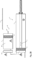
- FIG. 1 illustrated embodiment of a non-inventive coating agent supply device described, which can be arranged for example on a robot arm of a painting robot, as in the already mentioned above document WO 2004/037436 A1 is described for a conventional coating agent supply device, so that the contents of this document with respect to the structure and operation of the painting robot and the other components of the present description is fully attributable.
- the illustrated coating agent supply device has a coating agent metering device 1, which in this exemplary embodiment is a piston metering device.
- the coating agent metering device 1 has a cylinder 2 and a metering piston 3 displaceable in the cylinder 2 in the direction of the arrow, the drive of the metering piston 3 being effected mechanically by a push rod 4, which can be driven, for example, by an electric motor, pneumatically or hydraulically.
- a metering volume 5 which is adjustable by a displacement of the metering piston 3 in the cylinder 2.
- the metering volume 5 with the coating agent contained therein (eg water-based paint) is in operation at a high voltage potential, as symbolized by the high voltage symbol shown.
- the coating agent delivered by the coating agent supply device is therefore also at a high-voltage potential, which contributes to a good application efficiency in the case of an electrostatic coating.
- the metering volume 5 opposite side of the cylinder 2 and the push rod 4, however, is at a ground potential, as symbolized by the grounding sign also shown.
- For electrical isolation of the cylinder 2 and the push rod 4 therefore consist of an electrically insulating material.
- the material of the cylinder 2 and the push rod 4 must On the other hand, however, be sufficiently rigid in order to achieve a sufficient metering accuracy.
- the materials and structural details required for potential separation are, for example, in the document DE 102 33 633 A1 so that the contents of this document are fully attributable to the structure and operation of the coating agent metering device 1 of the present specification.
- a coating agent storage container 6 which consists essentially of a cylinder 7 and a displaceable in the cylinder 7 accumulator piston 8, wherein the accumulator piston 8 is pneumatically driven via a compressed air line 9 and thus an adjustable storage volume 10 in the cylinder 7 includes.
- the entire coating agent storage container 6 is in this case at a ground potential, as symbolized by the grounding symbol.
- the supply of the coating agent storage container 6 is effected by a coating agent supply line 11, which opens into the storage volume 10 and emanates, for example, from a conventional color changer or a loop.
- the withdrawn volume flow also depends on the viscosity of the removed coating agent.
- a low viscosity of the coating agent leads to a relatively large volume flow from the loop.
- a high viscosity of the coating agent leads to a correspondingly low volume flow during removal.
- the viscosity of the coating agent is therefore preferably taken into account, so that the filling of the coating agent storage container 6 is always independent of the viscosity of the coating agent with a constant low flow rate.
- the filling of the coating agent storage container 6 is preferably carried out until the accumulator piston 8 abuts a predetermined stop, whereby the maintenance of a defined filling quantity is ensured.
- the pneumatic backpressure on the accumulator piston 8 is set at the beginning of a removal to a predetermined value and then not regulated.
- the back pressure is then not regulated, but increases with increasing filling of the coating agent storage container 6 accordingly, so that the back pressure is a measure of the degree of filling of the coating agent storage container 6.
- the back pressure is continuously measured.
- the filling of the coating agent storage container 6 is then terminated. At a defined initial volume flow at the beginning of the filling of the coating agent storage container 6 is filled in this way with a defined amount of the coating agent.
- the coating agent storage container 6 From the storage volume 10 of the coating agent storage container 6 further branches off an insulation tube 12, which opens into the metering volume 5 of the coating agent metering 1, the insulation tube 12 in the deflated and cleaned state, the coating agent storage container 6 with respect to the coating agent metering device 1 electrically insulated , which in itself from the already mentioned document WO 2004/037436 A1 is known, so that its content in terms of the structure and operation of the insulating tube 12 of the present description is fully attributable.
- the insulation tube 12 has a larger line cross-section than the coating supply line 11, so that the coating agent metering device 1 can be filled as quickly as possible from the coating agent storage container 6, as will be described in detail.
- the smaller line cross section of the coating agent supply line 11 is harmless, since the filling of the coating agent storage container 6 takes place during painting, so that sufficient time is available for the filling of the coating agent storage container 6.
- the lower cost of the smaller cross-section of the coating agent supply line 11 is advantageous since smaller lines can be used.
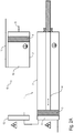
- FIGS. 2A and 2 B show an alternative embodiment of a coating agent supply device according to the invention, which is largely similar to that described above and in FIG. 1 corresponds to the embodiment shown, so that to avoid repetition of the above description FIG. 1 is referenced.
- a special feature of this exemplary embodiment is that the coating agent storage container 6 in this case is not permanently connected to the coating agent metering device 1 via the insulation tube 12. Instead, the coating agent storage container 6 is movable between two positions, which in the FIGS. 2A and 2 B are shown.
- FIG. 2A shown position of the coating agent storage container 6 is connected to the coating agent supply line 11, but separated from the coating agent metering device 1 and is then at an electrical ground potential. In this position, the filling of the coating agent storage container 6 takes place via the coating agent supply line 11.
- the coating agent storage container 6 is connected via a docking interface 13 with the coating agent metering device 1, but separated from the coating agent supply line 11 and is then at the same high-voltage potential as the coating agent metering device 1. In this position, the transfer of the coating agent from the coating agent storage container 6 takes place in the coating agent metering device 1.
- the coating agent storage container 6 is first filled with the new coating agent via the coating agent supply line 11, the coating agent storage container 6 being separated from the docking interface 13, as in FIG. 2A is shown. During this filling of the coating agent storage container 6, the coating agent metering device 1 can continue to meter the old coating agent, so that no filling of the coating agent storage container 6 is required to interrupt the painting process and therefore sufficient time is available for the filling.
- the coating agent storage container 6 After filling of the coating agent storage container 6, the coating agent storage container 6 is then connected after further intermediate steps with the docking interface 13, which in FIG. 2B is shown. After the connection with the docking interface 13 has been established, the new coating agent contained in the storage volume 7 can then be transferred into the metering volume 5 of the coating agent metering device 1.
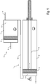
- FIG. 3 shows a simplified representation of a painting robot 21 with a coating agent supply device according to the invention, which largely coincides with the coating agent supply devices described above, so reference is made to avoid repetition of the above description.
- the coating agent metering device 1 is embodied here as a piston dispenser and integrated into an atomizer 22, which is mounted on a hand axis 23 and is guided by a highly mobile robot arm 24.
- the coating agent storage container 6 is arranged stationarily outside the painting robot 21 and can be connected to the coating agent metering device 1 via the docking interface 13.
- the painting robot 21 moves the atomizer 22 so that the docking interface 13 docks onto the coating agent storage container 6, whereupon the coating agent metering device 1 can be filled from the coating agent storage container 6.
- the drawing shows an alternative variant in which the dashed line coating agent metering 1 is integrated into the robot arm 24.
Claims (8)
- Dispositif d'alimentation pour un agent de revêtement pour une installation de peinture, aveca) un pulvérisateur (22),b) un robot de peinture (21) destiné au guidage du pulvérisateur (22),c) un doseur d'agent de revêtement (1), le doseur d'agent de revêtement (1)c1) dosant un agent de revêtement à appliquer en direction du pulvérisateur (22),c2) étant un doseur à piston qui présente un cylindre (2) et un piston doseur (3) coulissant dans le cylindre (2), etc3) et étant au moins par moments à un potentiel haute tension,c4) étant disposé dans le pulvérisateur (22) guidé par le robot de peinture (21) et se déplaçant avec le robot de peinture (21),d) une conduite annulaire (38), ete) une interface d'arrimage (13),
caractérisé en ce quef) le dispositif d'alimentation pour un agent de revêtement présente un réservoir de stockage d'agent de revêtement (6) pour la réception temporaire de l'agent de revêtement et pour l'alimentation du doseur d'agent de revêtement (1) en agent de revêtement, le réservoir de stockage d'agent de revêtement (6)f1) étant disposé en amont du doseur d'agent de revêtement (1) et étant, côté sortie, raccordé au doseur d'agent de revêtement (1),f2) étant disposé de façon stationnaire etf3) étant à un potentiel proche de la terre, etf4) étant rempli à partir de la conduite annulaire (38), etg) en ce que le doseur d'agent de revêtement (1) peut être raccordé de façon séparable au réservoir de stockage d'agent de revêtement (6) par le biais de l'interface d'arrimage (13). - Dispositif d'alimentation pour un agent de revêtement selon la revendication 1, caractérisé en ce quea) le réservoir de stockage d'agent de revêtement (6) présente un volume de stockage (10) réglable, et/oub) en ce que le volume de stockage (10) du réservoir de stockage d'agent de revêtement (6) peut être réglé par un piston (8), et/ouc) en ce que le piston (8) du réservoir de stockage d'agent de revêtement (6) est entraîné par moteur électrique, actionné par air comprimé ou entraîné par voie hydraulique.
- Installation de peinture avec un dispositif d'alimentation pour un agent de revêtement selon l'une des revendications précédentes.
- Procédé de fonctionnement pour un dispositif d'alimentation pour un agent de revêtement selon l'une des revendications 1 à 2, avec les étapes suivantes :a) dosage d'un agent de revêtement par un doseur d'agent de revêtement (1) en direction d'un pulvérisateur (22),b) alimentation du doseur d'agent de revêtement (1) en agent de revêtement par le biais d'un réservoir de stockage d'agent de revêtement (6) qui est disposé en amont du doseur d'agent de revêtement (1) et est, côté sortie, raccordé au doseur d'agent de revêtement (1),c) remplissage du réservoir de stockage d'agent de revêtement (6) avec l'agent de revêtement par le biais d'une conduite d'amenée d'agent de revêtement sous la forme d'une conduite annulaire (38), le réservoir de stockage d'agent de revêtement étant raccordé à la conduite d'amenée d'agent de revêtement de façon fixe,d) mise à la terre électrique du pulvérisateur (22) après un processus d'application,e) arrimage du pulvérisateur (22) mis à la terre avec le doseur d'agent de revêtement sur le réservoir de stockage d'agent de revêtement au moyen d'un robot de peinture, le robot de peinture guidant le pulvérisateur (22) de façon très mobile,f) transvasement de l'agent de revêtement à partir du réservoir de stockage d'agent de revêtement vers le doseur d'agent de revêtement quand le doseur d'agent de revêtement est amarré au réservoir de stockage d'agent de revêtement,g) désarrimage du pulvérisateur (22) avec le doseur d'agent de revêtement à partir du réservoir de stockage d'agent de revêtement après le transvasement,h) application de l'agent de revêtement.
- Procédé de fonctionnement selon la revendication 4, caractérisé par les étapes suivantes lors d'un changement de peinture à partir d'un ancien agent de revêtement vers un nouvel agent de revêtement :a) remplissage du réservoir de stockage d'agent de revêtement (6) avec le nouvel agent de revêtement à partir d'une conduite d'amenée d'agent de revêtement (11) pendant le dosage de l'ancien agent de revêtement par le doseur d'agent de revêtement (1),b) arrêt du dosage de l'ancien agent de revêtement par le doseur d'agent de revêtement (1),c) remplissage du doseur d'agent de revêtement (1) avec le nouvel agent de revêtement à partir du réservoir de stockage d'agent de revêtement (6),d) début du dosage du nouvel agent de revêtement par le doseur d'agent de revêtement (1).
- Procédé de fonctionnement selon la revendication 5, caractérisé par les étapes suivantes :- vidage de l'ancien agent de revêtement qui reste à partir du doseur d'agent de revêtement (1) après l'arrêt du dosage de l'ancien agent de revêtement et avant le remplissage du doseur d'agent de revêtement (1) avec le nouvel agent de revêtement, et/ou- lavage du doseur d'agent de revêtement (1) avec un agent de lavage après le vidage de l'ancien agent de revêtement à partir du doseur d'agent de revêtement (1) et avant le remplissage du doseur d'agent de revêtement (1) avec le nouvel agent de revêtement, et/ou- renvoi dans la conduite d'amenée d'agent de revêtement (11) du nouvel agent de revêtement résiduel restant dans le réservoir de stockage d'agent de revêtement (6) après le remplissage du doseur d'agent de revêtement (1), et/ou- lavage du réservoir de stockage d'agent de revêtement (6) avec un liquide de lavage après le renvoi dans la conduite d'amenée d'agent de revêtement (11) du nouvel agent de revêtement qui y reste.
- Procédé de fonctionnement selon l'une des revendications 4 à 6, caractérisé par l'étape suivante :
application d'un potentiel haute tension sur le doseur d'agent de revêtement et sur le pulvérisateur (22). - Procédé de fonctionnement selon l'une des revendications 4 à 7, caractérisé en ce quea) le remplissage du réservoir de stockage d'agent de revêtement (6) s'effectue avec un flux d'agent de revêtement plus faible que le dosage de l'agent de revêtement par le doseur d'agent de revêtement (1) et/ou que le remplissage du doseur d'agent de revêtement (1), et/oub) en ce que le réservoir de stockage d'agent de revêtement (6) présente un volume de stockage (10) qui peut être réglé par un piston (8) coulissant, le piston (8) étant soumis par voie pneumatique à une contre-pression qui dépend de la viscosité de l'agent de revêtement, et/ouc) en ce que la contre-pression est réglée de telle sorte que le flux volumique lors du remplissage du réservoir de stockage d'agent de revêtement (6) est indépendant de la viscosité de l'agent de revêtement.
Applications Claiming Priority (3)
| Application Number | Priority Date | Filing Date | Title |
|---|---|---|---|
| DE102005048223A DE102005048223A1 (de) | 2005-10-07 | 2005-10-07 | Beschichtungsmittel-Versorgungseinrichtung und zugehöriges Betriebsverfahren |
| DE102005060959A DE102005060959A1 (de) | 2005-10-07 | 2005-12-20 | Beschichtungsmittel-Versorgungseinrichtung und zugehöriges Betriebsverfahren |
| EP06021045.7A EP1772194B1 (fr) | 2005-10-07 | 2006-10-06 | Dispositif d'alimentation pour un agent de revêtement et correspondant procédé de fonctionnement |
Related Parent Applications (2)
| Application Number | Title | Priority Date | Filing Date |
|---|---|---|---|
| EP06021045.7A Division EP1772194B1 (fr) | 2005-10-07 | 2006-10-06 | Dispositif d'alimentation pour un agent de revêtement et correspondant procédé de fonctionnement |
| EP06021045.7A Division-Into EP1772194B1 (fr) | 2005-10-07 | 2006-10-06 | Dispositif d'alimentation pour un agent de revêtement et correspondant procédé de fonctionnement |
Publications (2)
| Publication Number | Publication Date |
|---|---|
| EP2810719A1 EP2810719A1 (fr) | 2014-12-10 |
| EP2810719B1 true EP2810719B1 (fr) | 2018-06-20 |
Family
ID=37564099
Family Applications (2)
| Application Number | Title | Priority Date | Filing Date |
|---|---|---|---|
| EP14002527.1A Revoked EP2810719B1 (fr) | 2005-10-07 | 2006-10-06 | Dispositif d'alimentation pour un agent de revêtement et correspondant procédé de fonctionnement |
| EP06021045.7A Active EP1772194B1 (fr) | 2005-10-07 | 2006-10-06 | Dispositif d'alimentation pour un agent de revêtement et correspondant procédé de fonctionnement |
Family Applications After (1)
| Application Number | Title | Priority Date | Filing Date |
|---|---|---|---|
| EP06021045.7A Active EP1772194B1 (fr) | 2005-10-07 | 2006-10-06 | Dispositif d'alimentation pour un agent de revêtement et correspondant procédé de fonctionnement |
Country Status (4)
| Country | Link |
|---|---|
| EP (2) | EP2810719B1 (fr) |
| DE (1) | DE202006021283U1 (fr) |
| ES (2) | ES2685244T3 (fr) |
| HU (1) | HUE043560T2 (fr) |
Families Citing this family (4)
| Publication number | Priority date | Publication date | Assignee | Title |
|---|---|---|---|---|
| US8020784B2 (en) | 2005-10-07 | 2011-09-20 | Durr Systems Inc. | Coating material supply installation and associated operating procedure |
| DE102007029195A1 (de) | 2007-06-25 | 2009-02-19 | Dürr Systems GmbH | Beschichtungseinrichtung mit einer Dosiervorrichtung |
| EP2101925B1 (fr) | 2006-12-12 | 2015-01-07 | Dürr Systems GmbH | Dispositif de revêtement équipé d'un dispositif de dosage |
| DE102020104325A1 (de) * | 2020-02-19 | 2021-08-19 | Dürr Systems Ag | Spülvorrichtung zum Verbinden mit einem Applikationsmittel-Hauptkanal eines Applikationsmittelwechslers |
Citations (26)
| Publication number | Priority date | Publication date | Assignee | Title |
|---|---|---|---|---|
| US4313475A (en) | 1980-06-26 | 1982-02-02 | The Gyromat Corporation | Voltage block system for electrostatic coating with conductive materials |
| WO1987005832A1 (fr) | 1986-03-24 | 1987-10-08 | Leif Tilly | Procede d'acheminement d'un milieu en suspension electro-conducteur et dispositif de realisation dudit procede |
| EP0274322A1 (fr) * | 1987-01-02 | 1988-07-13 | Sames S.A. | Installation de projection de produit de revêtement tel que par exemple une peinture et notamment installation de projection électrostatique de peinture à base d'eau |
| EP0428435A1 (fr) | 1989-11-14 | 1991-05-22 | Sames S.A. | Installation d'application de produit de revêtement conducteur, par voie électrostatique |
| FR2662620A1 (fr) | 1990-05-31 | 1991-12-06 | Sames Sa | Installation de projection de produit de revetement pulverise a debit controle. |
| EP0467626A1 (fr) | 1990-07-18 | 1992-01-22 | Nordson Corporation | Perfectionnement dans et concernant l'isolation électrostatique et le pompage de matériaux de revêtement conducteurs |
| EP0487378A1 (fr) | 1990-11-20 | 1992-05-27 | Sames S.A. | Installation de projection électrostatique de produit de revêtement liquide conducteur |
| US5197676A (en) | 1990-07-18 | 1993-03-30 | Nordson Corporation | Apparatus for dispensing conductive coating materials |
| WO1993006936A1 (fr) | 1991-10-04 | 1993-04-15 | Gmfanuc Robotics Corporation | Procede et systeme de transfert de fluides et capteur sans contact incorpore |
| WO1994022590A1 (fr) | 1993-04-01 | 1994-10-13 | Sames S.A. | Machine de projection de produit de revetement |
| GB2282085A (en) | 1993-08-18 | 1995-03-29 | John Stephen Griffiths | Paint supply apparatus |
| EP0693319A1 (fr) | 1994-07-13 | 1996-01-24 | Sames S.A. | Dispositif de projection comprenant un réservoir de produit de revêtement et procédé de nettoyage ou de remplissage d'un tel réservoir |
| FR2777482A1 (fr) * | 1998-04-15 | 1999-10-22 | Sames Sa | Procede et installation de projection de produit de revetement au moyen d'un automate equipe d'un reservoir |
| WO2001015816A1 (fr) | 1999-08-30 | 2001-03-08 | Sames Technologies | Dispositif de projection de produit de revetement comprenant au moins un projecteur et un reservoir a piston |
| WO2001015814A1 (fr) | 1999-08-30 | 2001-03-08 | Sames Technologies | Procede et station de changement de produit dans une installation de projection de produit de revetement |
| EP1108474A2 (fr) | 1999-12-18 | 2001-06-20 | INLAC Industrie-Lackieranlagen GmbH | Installation de peinture |
| FR2808709A1 (fr) | 2000-05-15 | 2001-11-16 | Eisenmann France Sarl | Procede de recuperation d'un fluide de revetement, tel qu'une peinture, contenu dans une installation |
| FR2811917A1 (fr) | 2000-07-24 | 2002-01-25 | Sames Sa | Procede et station de changement de produit dans une installation de projection de produit de revetement |
| FR2813538A1 (fr) | 2000-09-05 | 2002-03-08 | Eisenmann France Sarl | Procede et dispositif pour le remplissage d'un reservoir de peinture, dans une installation automatisee de peinture |
| WO2002032586A1 (fr) | 2000-10-19 | 2002-04-25 | Sames Technologies | Dispositif et procede d'alimentation de projecteurs et installation de projection equipee d'un tel dispositif |
| WO2002092236A2 (fr) | 2001-05-16 | 2002-11-21 | Fanuc Robotics North America, Inc. | Dispositif d'isolation electrique et de changement de couleur pour applicateur en cloche de peinture a base d'eau |
| EP1314483A2 (fr) | 2001-11-27 | 2003-05-28 | Dürr Systems GmbH | Procédé et système de distribution de doses de matériau de revêtement à un appareil de revêment |
| US6612345B1 (en) | 1999-05-06 | 2003-09-02 | Abb K.K. | Cartridge paint-charging method and device therefor |
| DE10233633A1 (de) | 2002-07-24 | 2004-02-12 | Dürr Systems GmbH | Einrichtung zum Dosieren oder Fördern eines Fördermediums |
| WO2004037436A1 (fr) | 2002-10-23 | 2004-05-06 | Fanuc Robotics America, Inc. | Appareil robotise de peinture |
| EP1502656A2 (fr) | 2003-07-28 | 2005-02-02 | Dürr Systems GmbH | Méthode et système d'alimentation de peinture pour une installation de revêtement électrostatique et système de liaison pour cela |
Family Cites Families (25)
| Publication number | Priority date | Publication date | Assignee | Title |
|---|---|---|---|---|
| US4020866A (en) | 1973-12-03 | 1977-05-03 | The Gyromat Corporation | Pressure vessel for voltage block material supply system |
| JPS5895558A (ja) | 1981-11-30 | 1983-06-07 | Mazda Motor Corp | 自動車ボデイ塗装用ロボツト |
| DE3526958A1 (de) | 1985-07-27 | 1985-12-19 | Daimler-Benz Ag, 7000 Stuttgart | Im teach-in-verfahren programmierbarer lackierroboter |
| DE3644536C1 (de) | 1986-12-24 | 1987-11-19 | Basf Lacke & Farben | Vorrichtung fuer eine Wasserlackapplikation mit Hochrotationszerstaeubern ueber Direktaufladung oder Kontaktaufladung |
| DE3713999A1 (de) | 1987-04-27 | 1988-11-10 | Behr Industrieanlagen | Verfahren zum selbsttaetigen serienweisen beschichten von werkstuecken |
| DE8906341U1 (fr) | 1989-05-23 | 1989-07-13 | Sata - Farbspritztechnik Gmbh & Co, 7140 Ludwigsburg, De | |
| DE4013942A1 (de) | 1990-04-30 | 1991-10-31 | Behr Industrieanlagen | Anlage zum serienweisen beschichten von werkstuecken mit leitfaehigem beschichtungsmaterial |
| DE4013940A1 (de) | 1990-04-30 | 1991-10-31 | Behr Industrieanlagen | Verfahren und anlage zum serienweisen beschichten von werkstuecken mit leitfaehigem beschichtungsmaterial |
| FR2695327B1 (fr) | 1992-09-09 | 1995-07-07 | Sames Sa | Dispositif de projection électrostatique de produit de revêtement électriquement conducteur, muni d'un réservoir isolé adapté à contenir un tel produit. |
| JP3259075B2 (ja) | 1992-11-18 | 2002-02-18 | 本田技研工業株式会社 | 塗装装置の中間貯溜槽 |
| US5364035A (en) | 1993-12-20 | 1994-11-15 | Graco Inc. | High voltage sealing and isolation via dynamic seals |
| DE19524853C2 (de) | 1994-07-12 | 2000-02-24 | Ransburg Corp | Beschichtungsvorrichtung |
| JP3245040B2 (ja) | 1996-02-29 | 2002-01-07 | トリニティ工業株式会社 | 静電塗装機 |
| DE19610588B4 (de) | 1996-03-18 | 2010-08-05 | Dürr Systems GmbH | Beschichtungsmaschine mit auswechselbarem Behälter |
| JP3513050B2 (ja) | 1998-11-13 | 2004-03-31 | トヨタ自動車株式会社 | 塗装ロボットおよび塗装ロボットの組み立て方法 |
| DE10103067A1 (de) * | 2001-01-24 | 2002-07-25 | Duerr Systems Gmbh | Beschichtungsmaschine mit einem auswechselbaren Applikationsorgan |
| DE10108010A1 (de) | 2001-02-20 | 2002-08-29 | Duerr Systems Gmbh | Sprühvorrichtung mit mindestens einer Trennstelle |
| DE10115463A1 (de) | 2001-03-29 | 2002-10-02 | Duerr Systems Gmbh | Zerstäuber für eine Beschichtungsanlage und Verfahren zu seiner Materialversorgung |
| DE10140216B4 (de) | 2001-08-17 | 2006-02-09 | ITW Oberflächentechnik GmbH & Co. KG | Verfahren und Vorrichtung an einer Lackiereinrichtung zum Reinigen einer Lack-Förderleitung |
| DE10216581B4 (de) | 2002-04-14 | 2006-07-20 | Asis Gmbh | Versorgungsleitung für Beschichtungsanlagen, insbesondere Lackieranlagen |
| DE10304652A1 (de) | 2003-02-05 | 2004-08-19 | Dürr Systems GmbH | Roboter |
| DE10320147A1 (de) | 2003-05-06 | 2004-12-09 | Dürr Systems GmbH | Verfahren und Versorgungssystem zur dosierten Materialversorgung einer Beschichtungsvorrichtung |
| DE10335358A1 (de) | 2003-08-01 | 2005-03-10 | Duerr Systems Gmbh | Beschichtungsmittelwechsler |
| DE102004015117A1 (de) | 2004-03-27 | 2005-10-13 | Daimlerchrysler Ag | Spülvorrichtung |
| DE102004016951A1 (de) | 2004-04-06 | 2005-11-10 | Dürr Systems GmbH | Verfahren zum Fördern eines Beschichtungsmaterials und Beschichtungsmaschine |
-
2006
- 2006-10-06 ES ES14002527.1T patent/ES2685244T3/es active Active
- 2006-10-06 ES ES06021045T patent/ES2717116T3/es active Active
- 2006-10-06 HU HUE06021045A patent/HUE043560T2/hu unknown
- 2006-10-06 EP EP14002527.1A patent/EP2810719B1/fr not_active Revoked
- 2006-10-06 DE DE202006021283.3U patent/DE202006021283U1/de not_active Expired - Lifetime
- 2006-10-06 EP EP06021045.7A patent/EP1772194B1/fr active Active
Patent Citations (27)
| Publication number | Priority date | Publication date | Assignee | Title |
|---|---|---|---|---|
| US4313475A (en) | 1980-06-26 | 1982-02-02 | The Gyromat Corporation | Voltage block system for electrostatic coating with conductive materials |
| US4313475B1 (en) | 1980-06-26 | 1994-07-12 | Nordson Corp | Voltage block system for electrostatic coating with conductive materials |
| WO1987005832A1 (fr) | 1986-03-24 | 1987-10-08 | Leif Tilly | Procede d'acheminement d'un milieu en suspension electro-conducteur et dispositif de realisation dudit procede |
| EP0274322A1 (fr) * | 1987-01-02 | 1988-07-13 | Sames S.A. | Installation de projection de produit de revêtement tel que par exemple une peinture et notamment installation de projection électrostatique de peinture à base d'eau |
| EP0428435A1 (fr) | 1989-11-14 | 1991-05-22 | Sames S.A. | Installation d'application de produit de revêtement conducteur, par voie électrostatique |
| FR2662620A1 (fr) | 1990-05-31 | 1991-12-06 | Sames Sa | Installation de projection de produit de revetement pulverise a debit controle. |
| EP0467626A1 (fr) | 1990-07-18 | 1992-01-22 | Nordson Corporation | Perfectionnement dans et concernant l'isolation électrostatique et le pompage de matériaux de revêtement conducteurs |
| US5197676A (en) | 1990-07-18 | 1993-03-30 | Nordson Corporation | Apparatus for dispensing conductive coating materials |
| EP0487378A1 (fr) | 1990-11-20 | 1992-05-27 | Sames S.A. | Installation de projection électrostatique de produit de revêtement liquide conducteur |
| WO1993006936A1 (fr) | 1991-10-04 | 1993-04-15 | Gmfanuc Robotics Corporation | Procede et systeme de transfert de fluides et capteur sans contact incorpore |
| WO1994022590A1 (fr) | 1993-04-01 | 1994-10-13 | Sames S.A. | Machine de projection de produit de revetement |
| GB2282085A (en) | 1993-08-18 | 1995-03-29 | John Stephen Griffiths | Paint supply apparatus |
| EP0693319A1 (fr) | 1994-07-13 | 1996-01-24 | Sames S.A. | Dispositif de projection comprenant un réservoir de produit de revêtement et procédé de nettoyage ou de remplissage d'un tel réservoir |
| FR2777482A1 (fr) * | 1998-04-15 | 1999-10-22 | Sames Sa | Procede et installation de projection de produit de revetement au moyen d'un automate equipe d'un reservoir |
| US6612345B1 (en) | 1999-05-06 | 2003-09-02 | Abb K.K. | Cartridge paint-charging method and device therefor |
| WO2001015816A1 (fr) | 1999-08-30 | 2001-03-08 | Sames Technologies | Dispositif de projection de produit de revetement comprenant au moins un projecteur et un reservoir a piston |
| WO2001015814A1 (fr) | 1999-08-30 | 2001-03-08 | Sames Technologies | Procede et station de changement de produit dans une installation de projection de produit de revetement |
| EP1108474A2 (fr) | 1999-12-18 | 2001-06-20 | INLAC Industrie-Lackieranlagen GmbH | Installation de peinture |
| FR2808709A1 (fr) | 2000-05-15 | 2001-11-16 | Eisenmann France Sarl | Procede de recuperation d'un fluide de revetement, tel qu'une peinture, contenu dans une installation |
| FR2811917A1 (fr) | 2000-07-24 | 2002-01-25 | Sames Sa | Procede et station de changement de produit dans une installation de projection de produit de revetement |
| FR2813538A1 (fr) | 2000-09-05 | 2002-03-08 | Eisenmann France Sarl | Procede et dispositif pour le remplissage d'un reservoir de peinture, dans une installation automatisee de peinture |
| WO2002032586A1 (fr) | 2000-10-19 | 2002-04-25 | Sames Technologies | Dispositif et procede d'alimentation de projecteurs et installation de projection equipee d'un tel dispositif |
| WO2002092236A2 (fr) | 2001-05-16 | 2002-11-21 | Fanuc Robotics North America, Inc. | Dispositif d'isolation electrique et de changement de couleur pour applicateur en cloche de peinture a base d'eau |
| EP1314483A2 (fr) | 2001-11-27 | 2003-05-28 | Dürr Systems GmbH | Procédé et système de distribution de doses de matériau de revêtement à un appareil de revêment |
| DE10233633A1 (de) | 2002-07-24 | 2004-02-12 | Dürr Systems GmbH | Einrichtung zum Dosieren oder Fördern eines Fördermediums |
| WO2004037436A1 (fr) | 2002-10-23 | 2004-05-06 | Fanuc Robotics America, Inc. | Appareil robotise de peinture |
| EP1502656A2 (fr) | 2003-07-28 | 2005-02-02 | Dürr Systems GmbH | Méthode et système d'alimentation de peinture pour une installation de revêtement électrostatique et système de liaison pour cela |
Non-Patent Citations (1)
| Title |
|---|
| PAVEL SVEJDA: "Prozesse und Applikationsverfahren", 2003, ÉDITIONS VINCENTZ, ISBN: 978-3878707417 |
Also Published As
| Publication number | Publication date |
|---|---|
| EP2810719A1 (fr) | 2014-12-10 |
| HUE043560T2 (hu) | 2019-08-28 |
| ES2717116T3 (es) | 2019-06-19 |
| DE202006021283U1 (de) | 2014-08-27 |
| EP1772194B1 (fr) | 2019-01-09 |
| ES2685244T3 (es) | 2018-10-08 |
| EP1772194A3 (fr) | 2008-09-17 |
| EP1772194A2 (fr) | 2007-04-11 |
Similar Documents
| Publication | Publication Date | Title |
|---|---|---|
| EP0292778B1 (fr) | Procédé et installation de revêtement électrostatique avec un produit de revêtement conducteur | |
| DE10140216B4 (de) | Verfahren und Vorrichtung an einer Lackiereinrichtung zum Reinigen einer Lack-Förderleitung | |
| DE69827476T2 (de) | Beschichtungsvorrichtung mit einem drehenden sprühkopf | |
| EP1142649B1 (fr) | Procédé et appareil de revêtement | |
| DE10033987A1 (de) | Verfahren zur Versorgung eines Beschichtungsorgans für die elektrostatische Serienbeschichtung von Werkstücken und Versorgungssystem hierfür | |
| DE3440381A1 (de) | Verfahren und vorrichtung zum automatischen elektrostatischen spruehbeschichten | |
| EP1314483B1 (fr) | Procédé et système de distribution de doses de matériau de revêtement à un appareil de revêment | |
| EP1666158B1 (fr) | Procédé et dispositif de dosage pour l'alimentation en matériau d'un appareil de revêtement. | |
| EP2810719B1 (fr) | Dispositif d'alimentation pour un agent de revêtement et correspondant procédé de fonctionnement | |
| EP1344572B1 (fr) | Installation de peinture pour revêtir des objets par un revêtement liquide | |
| EP3171983B1 (fr) | Système de revêtement servant au revêtement d'objets | |
| DD270665A5 (de) | Verfahren und anlage zum elektrostatischen beschichten im leitfaehigem material | |
| EP0455111B1 (fr) | Installation pour revêtir en série des pièces d'oeuvre d'un matériau de revêtement conducteur | |
| DE60127273T2 (de) | Verfahren und vorrichtung zur befüllung eines farbbehälters in einer automatisch arbeitenden beschichtunganlage | |
| EP1369183B1 (fr) | Méthode et système d'alimentation de peinture pour une installation de revêtement électrostatique | |
| DE60304386T2 (de) | Verfahren und Farbversorgungssystem | |
| EP0455109B1 (fr) | Procédé et installation de revêtement en series de pièces avec un produit de revêtement conducteur | |
| DE102005060959A1 (de) | Beschichtungsmittel-Versorgungseinrichtung und zugehöriges Betriebsverfahren | |
| EP1516676B1 (fr) | Méthode d'utilisation un dispositif d'alimentation des produits | |
| EP0455106B1 (fr) | Procédé et installation pour revêtir en série des pièces d'oeuvre d'un matériau de revêtement conducteur | |
| DE102005048223A1 (de) | Beschichtungsmittel-Versorgungseinrichtung und zugehöriges Betriebsverfahren | |
| EP3313584B1 (fr) | Bloc changeur de poudre et système de distribution de poudre pourvu dudit bloc changeur de poudre | |
| EP3188844B1 (fr) | Système de revêtement permettant de revêtir des objets | |
| DE102022121063A1 (de) | Vorrichtung aufweisend einen Applikator mit einem Medientank zur Aufnahme eines zu applizierenden Mediums und eine Ladestation | |
| DE19715294C1 (de) | Lackieranlage und Verfahren zum Betreiben einer Lackieranlage |
Legal Events
| Date | Code | Title | Description |
|---|---|---|---|
| PUAI | Public reference made under article 153(3) epc to a published international application that has entered the european phase |
Free format text: ORIGINAL CODE: 0009012 |
|
| 17P | Request for examination filed |
Effective date: 20140721 |
|
| AC | Divisional application: reference to earlier application |
Ref document number: 1772194 Country of ref document: EP Kind code of ref document: P |
|
| AK | Designated contracting states |
Kind code of ref document: A1 Designated state(s): AT BE BG CH CY CZ DE DK EE ES FI FR GB GR HU IE IS IT LI LT LU LV MC NL PL PT RO SE SI SK TR |
|
| R17P | Request for examination filed (corrected) |
Effective date: 20150318 |
|
| RBV | Designated contracting states (corrected) |
Designated state(s): AT BE BG CH CY CZ DE DK EE ES FI FR GB GR HU IE IS IT LI LT LU LV MC NL PL PT RO SE SI SK TR |
|
| RAP1 | Party data changed (applicant data changed or rights of an application transferred) |
Owner name: DUERR SYSTEMS AG |
|
| STAA | Information on the status of an ep patent application or granted ep patent |
Free format text: STATUS: EXAMINATION IS IN PROGRESS |
|
| 17Q | First examination report despatched |
Effective date: 20161124 |
|
| GRAP | Despatch of communication of intention to grant a patent |
Free format text: ORIGINAL CODE: EPIDOSNIGR1 |
|
| RIC1 | Information provided on ipc code assigned before grant |
Ipc: B05B 5/16 20060101AFI20171026BHEP Ipc: B05B 13/04 20060101ALI20171026BHEP Ipc: B05B 12/08 20060101ALI20171026BHEP Ipc: B05B 12/14 20060101ALN20171026BHEP |
|
| STAA | Information on the status of an ep patent application or granted ep patent |
Free format text: STATUS: GRANT OF PATENT IS INTENDED |
|
| INTG | Intention to grant announced |
Effective date: 20171130 |
|
| GRAS | Grant fee paid |
Free format text: ORIGINAL CODE: EPIDOSNIGR3 |
|
| GRAA | (expected) grant |
Free format text: ORIGINAL CODE: 0009210 |
|
| STAA | Information on the status of an ep patent application or granted ep patent |
Free format text: STATUS: THE PATENT HAS BEEN GRANTED |
|
| AC | Divisional application: reference to earlier application |
Ref document number: 1772194 Country of ref document: EP Kind code of ref document: P |
|
| AK | Designated contracting states |
Kind code of ref document: B1 Designated state(s): AT BE BG CH CY CZ DE DK EE ES FI FR GB GR HU IE IS IT LI LT LU LV MC NL PL PT RO SE SI SK TR |
|
| REG | Reference to a national code |
Ref country code: GB Ref legal event code: FG4D Free format text: NOT ENGLISH |
|
| REG | Reference to a national code |
Ref country code: IE Ref legal event code: FG4D Free format text: LANGUAGE OF EP DOCUMENT: GERMAN |
|
| REG | Reference to a national code |
Ref country code: DE Ref legal event code: R096 Ref document number: 502006015930 Country of ref document: DE |
|
| REG | Reference to a national code |
Ref country code: AT Ref legal event code: REF Ref document number: 1010199 Country of ref document: AT Kind code of ref document: T Effective date: 20180715 |
|
| REG | Reference to a national code |
Ref country code: ES Ref legal event code: FG2A Ref document number: 2685244 Country of ref document: ES Kind code of ref document: T3 Effective date: 20181008 |
|
| REG | Reference to a national code |
Ref country code: FR Ref legal event code: PLFP Year of fee payment: 13 |
|
| REG | Reference to a national code |
Ref country code: NL Ref legal event code: MP Effective date: 20180620 |
|
| PG25 | Lapsed in a contracting state [announced via postgrant information from national office to epo] |
Ref country code: LT Free format text: LAPSE BECAUSE OF FAILURE TO SUBMIT A TRANSLATION OF THE DESCRIPTION OR TO PAY THE FEE WITHIN THE PRESCRIBED TIME-LIMIT Effective date: 20180620 Ref country code: FI Free format text: LAPSE BECAUSE OF FAILURE TO SUBMIT A TRANSLATION OF THE DESCRIPTION OR TO PAY THE FEE WITHIN THE PRESCRIBED TIME-LIMIT Effective date: 20180620 Ref country code: BG Free format text: LAPSE BECAUSE OF FAILURE TO SUBMIT A TRANSLATION OF THE DESCRIPTION OR TO PAY THE FEE WITHIN THE PRESCRIBED TIME-LIMIT Effective date: 20180920 Ref country code: SE Free format text: LAPSE BECAUSE OF FAILURE TO SUBMIT A TRANSLATION OF THE DESCRIPTION OR TO PAY THE FEE WITHIN THE PRESCRIBED TIME-LIMIT Effective date: 20180620 |
|
| REG | Reference to a national code |
Ref country code: LT Ref legal event code: MG4D |
|
| PG25 | Lapsed in a contracting state [announced via postgrant information from national office to epo] |
Ref country code: LV Free format text: LAPSE BECAUSE OF FAILURE TO SUBMIT A TRANSLATION OF THE DESCRIPTION OR TO PAY THE FEE WITHIN THE PRESCRIBED TIME-LIMIT Effective date: 20180620 Ref country code: GR Free format text: LAPSE BECAUSE OF FAILURE TO SUBMIT A TRANSLATION OF THE DESCRIPTION OR TO PAY THE FEE WITHIN THE PRESCRIBED TIME-LIMIT Effective date: 20180921 |
|
| PG25 | Lapsed in a contracting state [announced via postgrant information from national office to epo] |
Ref country code: NL Free format text: LAPSE BECAUSE OF FAILURE TO SUBMIT A TRANSLATION OF THE DESCRIPTION OR TO PAY THE FEE WITHIN THE PRESCRIBED TIME-LIMIT Effective date: 20180620 |
|
| PG25 | Lapsed in a contracting state [announced via postgrant information from national office to epo] |
Ref country code: SK Free format text: LAPSE BECAUSE OF FAILURE TO SUBMIT A TRANSLATION OF THE DESCRIPTION OR TO PAY THE FEE WITHIN THE PRESCRIBED TIME-LIMIT Effective date: 20180620 Ref country code: PL Free format text: LAPSE BECAUSE OF FAILURE TO SUBMIT A TRANSLATION OF THE DESCRIPTION OR TO PAY THE FEE WITHIN THE PRESCRIBED TIME-LIMIT Effective date: 20180620 Ref country code: EE Free format text: LAPSE BECAUSE OF FAILURE TO SUBMIT A TRANSLATION OF THE DESCRIPTION OR TO PAY THE FEE WITHIN THE PRESCRIBED TIME-LIMIT Effective date: 20180620 Ref country code: IS Free format text: LAPSE BECAUSE OF FAILURE TO SUBMIT A TRANSLATION OF THE DESCRIPTION OR TO PAY THE FEE WITHIN THE PRESCRIBED TIME-LIMIT Effective date: 20181020 Ref country code: RO Free format text: LAPSE BECAUSE OF FAILURE TO SUBMIT A TRANSLATION OF THE DESCRIPTION OR TO PAY THE FEE WITHIN THE PRESCRIBED TIME-LIMIT Effective date: 20180620 Ref country code: CZ Free format text: LAPSE BECAUSE OF FAILURE TO SUBMIT A TRANSLATION OF THE DESCRIPTION OR TO PAY THE FEE WITHIN THE PRESCRIBED TIME-LIMIT Effective date: 20180620 |
|
| REG | Reference to a national code |
Ref country code: DE Ref legal event code: R026 Ref document number: 502006015930 Country of ref document: DE |
|
| PLBI | Opposition filed |
Free format text: ORIGINAL CODE: 0009260 |
|
| PLAX | Notice of opposition and request to file observation + time limit sent |
Free format text: ORIGINAL CODE: EPIDOSNOBS2 |
|
| 26 | Opposition filed |
Opponent name: EXEL INDUSTRIES Effective date: 20190320 |
|
| PG25 | Lapsed in a contracting state [announced via postgrant information from national office to epo] |
Ref country code: DK Free format text: LAPSE BECAUSE OF FAILURE TO SUBMIT A TRANSLATION OF THE DESCRIPTION OR TO PAY THE FEE WITHIN THE PRESCRIBED TIME-LIMIT Effective date: 20180620 |
|
| REG | Reference to a national code |
Ref country code: CH Ref legal event code: PL |
|
| PLBB | Reply of patent proprietor to notice(s) of opposition received |
Free format text: ORIGINAL CODE: EPIDOSNOBS3 |
|
| GBPC | Gb: european patent ceased through non-payment of renewal fee |
Effective date: 20181006 |
|
| REG | Reference to a national code |
Ref country code: BE Ref legal event code: MM Effective date: 20181031 |
|
| PG25 | Lapsed in a contracting state [announced via postgrant information from national office to epo] |
Ref country code: LU Free format text: LAPSE BECAUSE OF NON-PAYMENT OF DUE FEES Effective date: 20181006 Ref country code: MC Free format text: LAPSE BECAUSE OF FAILURE TO SUBMIT A TRANSLATION OF THE DESCRIPTION OR TO PAY THE FEE WITHIN THE PRESCRIBED TIME-LIMIT Effective date: 20180620 |
|
| REG | Reference to a national code |
Ref country code: IE Ref legal event code: MM4A |
|
| PG25 | Lapsed in a contracting state [announced via postgrant information from national office to epo] |
Ref country code: SI Free format text: LAPSE BECAUSE OF FAILURE TO SUBMIT A TRANSLATION OF THE DESCRIPTION OR TO PAY THE FEE WITHIN THE PRESCRIBED TIME-LIMIT Effective date: 20180620 Ref country code: BE Free format text: LAPSE BECAUSE OF NON-PAYMENT OF DUE FEES Effective date: 20181031 Ref country code: CH Free format text: LAPSE BECAUSE OF NON-PAYMENT OF DUE FEES Effective date: 20181031 Ref country code: LI Free format text: LAPSE BECAUSE OF NON-PAYMENT OF DUE FEES Effective date: 20181031 |
|
| PG25 | Lapsed in a contracting state [announced via postgrant information from national office to epo] |
Ref country code: GB Free format text: LAPSE BECAUSE OF NON-PAYMENT OF DUE FEES Effective date: 20181006 Ref country code: IE Free format text: LAPSE BECAUSE OF NON-PAYMENT OF DUE FEES Effective date: 20181006 |
|
| REG | Reference to a national code |
Ref country code: AT Ref legal event code: MM01 Ref document number: 1010199 Country of ref document: AT Kind code of ref document: T Effective date: 20181006 |
|
| PG25 | Lapsed in a contracting state [announced via postgrant information from national office to epo] |
Ref country code: AT Free format text: LAPSE BECAUSE OF NON-PAYMENT OF DUE FEES Effective date: 20181006 |
|
| PG25 | Lapsed in a contracting state [announced via postgrant information from national office to epo] |
Ref country code: TR Free format text: LAPSE BECAUSE OF FAILURE TO SUBMIT A TRANSLATION OF THE DESCRIPTION OR TO PAY THE FEE WITHIN THE PRESCRIBED TIME-LIMIT Effective date: 20180620 |
|
| PG25 | Lapsed in a contracting state [announced via postgrant information from national office to epo] |
Ref country code: PT Free format text: LAPSE BECAUSE OF FAILURE TO SUBMIT A TRANSLATION OF THE DESCRIPTION OR TO PAY THE FEE WITHIN THE PRESCRIBED TIME-LIMIT Effective date: 20180620 |
|
| PG25 | Lapsed in a contracting state [announced via postgrant information from national office to epo] |
Ref country code: HU Free format text: LAPSE BECAUSE OF FAILURE TO SUBMIT A TRANSLATION OF THE DESCRIPTION OR TO PAY THE FEE WITHIN THE PRESCRIBED TIME-LIMIT; INVALID AB INITIO Effective date: 20061006 Ref country code: CY Free format text: LAPSE BECAUSE OF FAILURE TO SUBMIT A TRANSLATION OF THE DESCRIPTION OR TO PAY THE FEE WITHIN THE PRESCRIBED TIME-LIMIT Effective date: 20180620 |
|
| RIC2 | Information provided on ipc code assigned after grant |
Ipc: B05B 12/14 20060101ALN20210414BHEP Ipc: B05B 13/04 20060101ALI20210414BHEP Ipc: B05B 12/08 20060101ALI20210414BHEP Ipc: B05B 5/16 20060101AFI20210414BHEP |
|
| RIC2 | Information provided on ipc code assigned after grant |
Ipc: B05B 12/14 20060101ALN20210421BHEP Ipc: B05B 13/04 20060101ALI20210421BHEP Ipc: B05B 12/08 20060101ALI20210421BHEP Ipc: B05B 5/16 20060101AFI20210421BHEP |
|
| APAH | Appeal reference modified |
Free format text: ORIGINAL CODE: EPIDOSCREFNO |
|
| APBM | Appeal reference recorded |
Free format text: ORIGINAL CODE: EPIDOSNREFNO |
|
| APBP | Date of receipt of notice of appeal recorded |
Free format text: ORIGINAL CODE: EPIDOSNNOA2O |
|
| RIC2 | Information provided on ipc code assigned after grant |
Ipc: B05B 12/14 20060101ALN20210506BHEP Ipc: B05B 13/04 20060101ALI20210506BHEP Ipc: B05B 12/08 20060101ALI20210506BHEP Ipc: B05B 5/16 20060101AFI20210506BHEP |
|
| RIC2 | Information provided on ipc code assigned after grant |
Ipc: B05B 12/14 20060101ALN20210507BHEP Ipc: B05B 13/04 20060101ALI20210507BHEP Ipc: B05B 12/08 20060101ALI20210507BHEP Ipc: B05B 5/16 20060101AFI20210507BHEP |
|
| APBM | Appeal reference recorded |
Free format text: ORIGINAL CODE: EPIDOSNREFNO |
|
| APBP | Date of receipt of notice of appeal recorded |
Free format text: ORIGINAL CODE: EPIDOSNNOA2O |
|
| APBQ | Date of receipt of statement of grounds of appeal recorded |
Free format text: ORIGINAL CODE: EPIDOSNNOA3O |
|
| APBQ | Date of receipt of statement of grounds of appeal recorded |
Free format text: ORIGINAL CODE: EPIDOSNNOA3O |
|
| PGFP | Annual fee paid to national office [announced via postgrant information from national office to epo] |
Ref country code: FR Payment date: 20221031 Year of fee payment: 17 |
|
| PGFP | Annual fee paid to national office [announced via postgrant information from national office to epo] |
Ref country code: IT Payment date: 20221021 Year of fee payment: 17 Ref country code: ES Payment date: 20221222 Year of fee payment: 17 Ref country code: DE Payment date: 20221019 Year of fee payment: 17 |
|
| REG | Reference to a national code |
Ref country code: DE Ref legal event code: R103 Ref document number: 502006015930 Country of ref document: DE Ref country code: DE Ref legal event code: R064 Ref document number: 502006015930 Country of ref document: DE |
|
| APBU | Appeal procedure closed |
Free format text: ORIGINAL CODE: EPIDOSNNOA9O |
|
| RDAF | Communication despatched that patent is revoked |
Free format text: ORIGINAL CODE: EPIDOSNREV1 |
|
| STAA | Information on the status of an ep patent application or granted ep patent |
Free format text: STATUS: PATENT REVOKED |
|
| RDAG | Patent revoked |
Free format text: ORIGINAL CODE: 0009271 |
|
| REG | Reference to a national code |
Ref country code: CH Ref legal event code: PL |
|
| 27W | Patent revoked |
Effective date: 20230303 |
|
| P01 | Opt-out of the competence of the unified patent court (upc) registered |
Effective date: 20230512 |
|
| REG | Reference to a national code |
Ref country code: AT Ref legal event code: MA03 Ref document number: 1010199 Country of ref document: AT Kind code of ref document: T Effective date: 20230303 |