EP2809485B1 - Bohrvorrichtung und -verfahren - Google Patents
Bohrvorrichtung und -verfahren Download PDFInfo
- Publication number
- EP2809485B1 EP2809485B1 EP13703464.1A EP13703464A EP2809485B1 EP 2809485 B1 EP2809485 B1 EP 2809485B1 EP 13703464 A EP13703464 A EP 13703464A EP 2809485 B1 EP2809485 B1 EP 2809485B1
- Authority
- EP
- European Patent Office
- Prior art keywords
- panel
- robot
- drilling tool
- hole
- end effector
- Prior art date
- Legal status (The legal status is an assumption and is not a legal conclusion. Google has not performed a legal analysis and makes no representation as to the accuracy of the status listed.)
- Active
Links
Images


Classifications
-
- B—PERFORMING OPERATIONS; TRANSPORTING
- B23—MACHINE TOOLS; METAL-WORKING NOT OTHERWISE PROVIDED FOR
- B23B—TURNING; BORING
- B23B39/00—General-purpose boring or drilling machines or devices; Sets of boring and/or drilling machines
- B23B39/04—Co-ordinate boring or drilling machines; Machines for making holes without previous marking
- B23B39/08—Devices for program control
-
- B—PERFORMING OPERATIONS; TRANSPORTING
- B23—MACHINE TOOLS; METAL-WORKING NOT OTHERWISE PROVIDED FOR
- B23B—TURNING; BORING
- B23B39/00—General-purpose boring or drilling machines or devices; Sets of boring and/or drilling machines
- B23B39/14—General-purpose boring or drilling machines or devices; Sets of boring and/or drilling machines with special provision to enable the machine or the drilling or boring head to be moved into any desired position, e.g. with respect to immovable work
-
- B—PERFORMING OPERATIONS; TRANSPORTING
- B23—MACHINE TOOLS; METAL-WORKING NOT OTHERWISE PROVIDED FOR
- B23B—TURNING; BORING
- B23B35/00—Methods for boring or drilling, or for working essentially requiring the use of boring or drilling machines; Use of auxiliary equipment in connection with such methods
-
- B—PERFORMING OPERATIONS; TRANSPORTING
- B23—MACHINE TOOLS; METAL-WORKING NOT OTHERWISE PROVIDED FOR
- B23B—TURNING; BORING
- B23B39/00—General-purpose boring or drilling machines or devices; Sets of boring and/or drilling machines
- B23B39/28—Associations of only boring or drilling machines directed to a particular metal-working result
-
- B—PERFORMING OPERATIONS; TRANSPORTING
- B23—MACHINE TOOLS; METAL-WORKING NOT OTHERWISE PROVIDED FOR
- B23B—TURNING; BORING
- B23B41/00—Boring or drilling machines or devices specially adapted for particular work; Accessories specially adapted therefor
-
- B—PERFORMING OPERATIONS; TRANSPORTING
- B23—MACHINE TOOLS; METAL-WORKING NOT OTHERWISE PROVIDED FOR
- B23B—TURNING; BORING
- B23B49/00—Measuring or gauging equipment on boring machines for positioning or guiding the drill; Devices for indicating failure of drills during boring; Centering devices for holes to be bored
- B23B49/003—Stops attached to drilling tools, tool holders or drilling machines
- B23B49/006—Attached to drilling machines
- B23B49/008—Attached to the nose of the drilling machines
-
- B—PERFORMING OPERATIONS; TRANSPORTING
- B23—MACHINE TOOLS; METAL-WORKING NOT OTHERWISE PROVIDED FOR
- B23Q—DETAILS, COMPONENTS, OR ACCESSORIES FOR MACHINE TOOLS, e.g. ARRANGEMENTS FOR COPYING OR CONTROLLING; MACHINE TOOLS IN GENERAL CHARACTERISED BY THE CONSTRUCTION OF PARTICULAR DETAILS OR COMPONENTS; COMBINATIONS OR ASSOCIATIONS OF METAL-WORKING MACHINES, NOT DIRECTED TO A PARTICULAR RESULT
- B23Q15/00—Automatic control or regulation of feed movement, cutting velocity or position of tool or work
- B23Q15/007—Automatic control or regulation of feed movement, cutting velocity or position of tool or work while the tool acts upon the workpiece
- B23Q15/18—Compensation of tool-deflection due to temperature or force
-
- B—PERFORMING OPERATIONS; TRANSPORTING
- B25—HAND TOOLS; PORTABLE POWER-DRIVEN TOOLS; MANIPULATORS
- B25J—MANIPULATORS; CHAMBERS PROVIDED WITH MANIPULATION DEVICES
- B25J9/00—Program-controlled manipulators
- B25J9/16—Program controls
-
- B—PERFORMING OPERATIONS; TRANSPORTING
- B25—HAND TOOLS; PORTABLE POWER-DRIVEN TOOLS; MANIPULATORS
- B25J—MANIPULATORS; CHAMBERS PROVIDED WITH MANIPULATION DEVICES
- B25J9/00—Program-controlled manipulators
- B25J9/16—Program controls
- B25J9/1656—Program controls characterised by programming, planning systems for manipulators
- B25J9/1671—Program controls characterised by programming, planning systems for manipulators characterised by simulation, either to verify existing program or to create and verify new program, CAD/CAM oriented, graphic oriented programming systems
-
- B—PERFORMING OPERATIONS; TRANSPORTING
- B25—HAND TOOLS; PORTABLE POWER-DRIVEN TOOLS; MANIPULATORS
- B25J—MANIPULATORS; CHAMBERS PROVIDED WITH MANIPULATION DEVICES
- B25J9/00—Program-controlled manipulators
- B25J9/16—Program controls
- B25J9/1679—Program controls characterised by the tasks executed
- B25J9/1682—Dual arm manipulator; Coordination of several manipulators
-
- G—PHYSICS
- G05—CONTROLLING; REGULATING
- G05B—CONTROL OR REGULATING SYSTEMS IN GENERAL; FUNCTIONAL ELEMENTS OF SUCH SYSTEMS; MONITORING OR TESTING ARRANGEMENTS FOR SUCH SYSTEMS OR ELEMENTS
- G05B19/00—Program-control systems
- G05B19/02—Program-control systems electric
- G05B19/18—Numerical control [NC], i.e. automatically operating machines, in particular machine tools, e.g. in a manufacturing environment, so as to execute positioning, movement or co-ordinated operations by means of program data in numerical form
- G05B19/406—Numerical control [NC], i.e. automatically operating machines, in particular machine tools, e.g. in a manufacturing environment, so as to execute positioning, movement or co-ordinated operations by means of program data in numerical form characterised by monitoring or safety
- G05B19/4069—Simulating machining process on screen
-
- G—PHYSICS
- G05—CONTROLLING; REGULATING
- G05B—CONTROL OR REGULATING SYSTEMS IN GENERAL; FUNCTIONAL ELEMENTS OF SUCH SYSTEMS; MONITORING OR TESTING ARRANGEMENTS FOR SUCH SYSTEMS OR ELEMENTS
- G05B19/00—Program-control systems
- G05B19/02—Program-control systems electric
- G05B19/18—Numerical control [NC], i.e. automatically operating machines, in particular machine tools, e.g. in a manufacturing environment, so as to execute positioning, movement or co-ordinated operations by means of program data in numerical form
- G05B19/4097—Numerical control [NC], i.e. automatically operating machines, in particular machine tools, e.g. in a manufacturing environment, so as to execute positioning, movement or co-ordinated operations by means of program data in numerical form characterised by using design data to control NC machines, e.g. CAD/CAM
- G05B19/4099—Surface or curve machining, making three-dimensional [3D] objects, e.g. desktop manufacturing
-
- B—PERFORMING OPERATIONS; TRANSPORTING
- B23—MACHINE TOOLS; METAL-WORKING NOT OTHERWISE PROVIDED FOR
- B23B—TURNING; BORING
- B23B2215/00—Details of workpieces
- B23B2215/04—Aircraft components
-
- B—PERFORMING OPERATIONS; TRANSPORTING
- B23—MACHINE TOOLS; METAL-WORKING NOT OTHERWISE PROVIDED FOR
- B23B—TURNING; BORING
- B23B2220/00—Details of turning, boring or drilling processes
- B23B2220/04—Chamferring
-
- B—PERFORMING OPERATIONS; TRANSPORTING
- B23—MACHINE TOOLS; METAL-WORKING NOT OTHERWISE PROVIDED FOR
- B23B—TURNING; BORING
- B23B2260/00—Details of constructional elements
- B23B2260/128—Sensors
-
- B—PERFORMING OPERATIONS; TRANSPORTING
- B23—MACHINE TOOLS; METAL-WORKING NOT OTHERWISE PROVIDED FOR
- B23B—TURNING; BORING
- B23B2270/00—Details of turning, boring or drilling machines, processes or tools not otherwise provided for
- B23B2270/48—Measuring or detecting
-
- G—PHYSICS
- G05—CONTROLLING; REGULATING
- G05B—CONTROL OR REGULATING SYSTEMS IN GENERAL; FUNCTIONAL ELEMENTS OF SUCH SYSTEMS; MONITORING OR TESTING ARRANGEMENTS FOR SUCH SYSTEMS OR ELEMENTS
- G05B2219/00—Program-control systems
- G05B2219/30—Nc systems
- G05B2219/39—Robotics, robotics to robotics hand
- G05B2219/39109—Dual arm, multiarm manipulation, object handled in cooperation
-
- G—PHYSICS
- G05—CONTROLLING; REGULATING
- G05B—CONTROL OR REGULATING SYSTEMS IN GENERAL; FUNCTIONAL ELEMENTS OF SUCH SYSTEMS; MONITORING OR TESTING ARRANGEMENTS FOR SUCH SYSTEMS OR ELEMENTS
- G05B2219/00—Program-control systems
- G05B2219/30—Nc systems
- G05B2219/39—Robotics, robotics to robotics hand
- G05B2219/39116—Constraint object handled in cooperation
-
- G—PHYSICS
- G05—CONTROLLING; REGULATING
- G05B—CONTROL OR REGULATING SYSTEMS IN GENERAL; FUNCTIONAL ELEMENTS OF SUCH SYSTEMS; MONITORING OR TESTING ARRANGEMENTS FOR SUCH SYSTEMS OR ELEMENTS
- G05B2219/00—Program-control systems
- G05B2219/30—Nc systems
- G05B2219/39—Robotics, robotics to robotics hand
- G05B2219/39121—Two manipulators operate on same object
-
- G—PHYSICS
- G05—CONTROLLING; REGULATING
- G05B—CONTROL OR REGULATING SYSTEMS IN GENERAL; FUNCTIONAL ELEMENTS OF SUCH SYSTEMS; MONITORING OR TESTING ARRANGEMENTS FOR SUCH SYSTEMS OR ELEMENTS
- G05B2219/00—Program-control systems
- G05B2219/30—Nc systems
- G05B2219/39—Robotics, robotics to robotics hand
- G05B2219/39129—One manipulator holds one piece, other inserts, screws other piece, dexterity
-
- G—PHYSICS
- G05—CONTROLLING; REGULATING
- G05B—CONTROL OR REGULATING SYSTEMS IN GENERAL; FUNCTIONAL ELEMENTS OF SUCH SYSTEMS; MONITORING OR TESTING ARRANGEMENTS FOR SUCH SYSTEMS OR ELEMENTS
- G05B2219/00—Program-control systems
- G05B2219/30—Nc systems
- G05B2219/45—Nc applications
- G05B2219/45059—Drilling robot
-
- G—PHYSICS
- G05—CONTROLLING; REGULATING
- G05B—CONTROL OR REGULATING SYSTEMS IN GENERAL; FUNCTIONAL ELEMENTS OF SUCH SYSTEMS; MONITORING OR TESTING ARRANGEMENTS FOR SUCH SYSTEMS OR ELEMENTS
- G05B2219/00—Program-control systems
- G05B2219/30—Nc systems
- G05B2219/49—Nc machine tool, till multiple
- G05B2219/49113—Align elements like hole and drill, centering tool, probe, workpiece
-
- Y—GENERAL TAGGING OF NEW TECHNOLOGICAL DEVELOPMENTS; GENERAL TAGGING OF CROSS-SECTIONAL TECHNOLOGIES SPANNING OVER SEVERAL SECTIONS OF THE IPC; TECHNICAL SUBJECTS COVERED BY FORMER USPC CROSS-REFERENCE ART COLLECTIONS [XRACs] AND DIGESTS
- Y10—TECHNICAL SUBJECTS COVERED BY FORMER USPC
- Y10S—TECHNICAL SUBJECTS COVERED BY FORMER USPC CROSS-REFERENCE ART COLLECTIONS [XRACs] AND DIGESTS
- Y10S901/00—Robots
- Y10S901/02—Arm motion controller
- Y10S901/09—Closed loop, sensor feedback controls arm movement
-
- Y—GENERAL TAGGING OF NEW TECHNOLOGICAL DEVELOPMENTS; GENERAL TAGGING OF CROSS-SECTIONAL TECHNOLOGIES SPANNING OVER SEVERAL SECTIONS OF THE IPC; TECHNICAL SUBJECTS COVERED BY FORMER USPC CROSS-REFERENCE ART COLLECTIONS [XRACs] AND DIGESTS
- Y10—TECHNICAL SUBJECTS COVERED BY FORMER USPC
- Y10S—TECHNICAL SUBJECTS COVERED BY FORMER USPC CROSS-REFERENCE ART COLLECTIONS [XRACs] AND DIGESTS
- Y10S901/00—Robots
- Y10S901/30—End effector
- Y10S901/41—Tool
-
- Y—GENERAL TAGGING OF NEW TECHNOLOGICAL DEVELOPMENTS; GENERAL TAGGING OF CROSS-SECTIONAL TECHNOLOGIES SPANNING OVER SEVERAL SECTIONS OF THE IPC; TECHNICAL SUBJECTS COVERED BY FORMER USPC CROSS-REFERENCE ART COLLECTIONS [XRACs] AND DIGESTS
- Y10—TECHNICAL SUBJECTS COVERED BY FORMER USPC
- Y10S—TECHNICAL SUBJECTS COVERED BY FORMER USPC CROSS-REFERENCE ART COLLECTIONS [XRACs] AND DIGESTS
- Y10S901/00—Robots
- Y10S901/46—Sensing device
- Y10S901/47—Optical
-
- Y—GENERAL TAGGING OF NEW TECHNOLOGICAL DEVELOPMENTS; GENERAL TAGGING OF CROSS-SECTIONAL TECHNOLOGIES SPANNING OVER SEVERAL SECTIONS OF THE IPC; TECHNICAL SUBJECTS COVERED BY FORMER USPC CROSS-REFERENCE ART COLLECTIONS [XRACs] AND DIGESTS
- Y10—TECHNICAL SUBJECTS COVERED BY FORMER USPC
- Y10T—TECHNICAL SUBJECTS COVERED BY FORMER US CLASSIFICATION
- Y10T408/00—Cutting by use of rotating axially moving tool
- Y10T408/03—Processes
-
- Y—GENERAL TAGGING OF NEW TECHNOLOGICAL DEVELOPMENTS; GENERAL TAGGING OF CROSS-SECTIONAL TECHNOLOGIES SPANNING OVER SEVERAL SECTIONS OF THE IPC; TECHNICAL SUBJECTS COVERED BY FORMER USPC CROSS-REFERENCE ART COLLECTIONS [XRACs] AND DIGESTS
- Y10—TECHNICAL SUBJECTS COVERED BY FORMER USPC
- Y10T—TECHNICAL SUBJECTS COVERED BY FORMER US CLASSIFICATION
- Y10T408/00—Cutting by use of rotating axially moving tool
- Y10T408/08—Cutting by use of rotating axially moving tool with means to regulate operation by use of templet, tape, card, or other replaceable information supply
-
- Y—GENERAL TAGGING OF NEW TECHNOLOGICAL DEVELOPMENTS; GENERAL TAGGING OF CROSS-SECTIONAL TECHNOLOGIES SPANNING OVER SEVERAL SECTIONS OF THE IPC; TECHNICAL SUBJECTS COVERED BY FORMER USPC CROSS-REFERENCE ART COLLECTIONS [XRACs] AND DIGESTS
- Y10—TECHNICAL SUBJECTS COVERED BY FORMER USPC
- Y10T—TECHNICAL SUBJECTS COVERED BY FORMER US CLASSIFICATION
- Y10T408/00—Cutting by use of rotating axially moving tool
- Y10T408/16—Cutting by use of rotating axially moving tool with control means energized in response to activator stimulated by condition sensor
- Y10T408/175—Cutting by use of rotating axially moving tool with control means energized in response to activator stimulated by condition sensor to control relative positioning of Tool and work
-
- Y—GENERAL TAGGING OF NEW TECHNOLOGICAL DEVELOPMENTS; GENERAL TAGGING OF CROSS-SECTIONAL TECHNOLOGIES SPANNING OVER SEVERAL SECTIONS OF THE IPC; TECHNICAL SUBJECTS COVERED BY FORMER USPC CROSS-REFERENCE ART COLLECTIONS [XRACs] AND DIGESTS
- Y10—TECHNICAL SUBJECTS COVERED BY FORMER USPC
- Y10T—TECHNICAL SUBJECTS COVERED BY FORMER US CLASSIFICATION
- Y10T408/00—Cutting by use of rotating axially moving tool
- Y10T408/21—Cutting by use of rotating axially moving tool with signal, indicator, illuminator or optical means
-
- Y—GENERAL TAGGING OF NEW TECHNOLOGICAL DEVELOPMENTS; GENERAL TAGGING OF CROSS-SECTIONAL TECHNOLOGIES SPANNING OVER SEVERAL SECTIONS OF THE IPC; TECHNICAL SUBJECTS COVERED BY FORMER USPC CROSS-REFERENCE ART COLLECTIONS [XRACs] AND DIGESTS
- Y10—TECHNICAL SUBJECTS COVERED BY FORMER USPC
- Y10T—TECHNICAL SUBJECTS COVERED BY FORMER US CLASSIFICATION
- Y10T408/00—Cutting by use of rotating axially moving tool
- Y10T408/55—Cutting by use of rotating axially moving tool with work-engaging structure other than Tool or tool-support
- Y10T408/561—Having tool-opposing, work-engaging surface
Definitions
- the present invention relates to drilling methods and apparatus.
- Countersinking of predrilled holes may be performed manually by human operators, e.g. using hand tools and workbenches.
- the panels may bend or deflect on the workbench due to the forces applied by the operator.
- the operator may manually compensate for such deflection.
- the operator may also compensate for curvature in the part being countersunk e.g. by manually adjusting the settings on the hand tool.
- large workforces and workspaces tend to be required for processing a large number of panels.
- the human operators may develop repetitive strain injury caused by repeated drilling.
- Countersinking of holes may also be performed using a machine tool (or robot).
- a machine tool or robot
- the use of such devices typically requires use of a secure fixture that rigidly supports a panel so as to prevent it deflecting under the cutting/drilling forces.
- Such machine tools can be very expensive.
- the fixtures which are usually required to be bespoke for the shape of panel being drilled, also tend to be expensive.
- German utility model DE 20 2008 014 886 U1 discloses a robot, in which for the riveting operation to members are pressed against the part.
- the operations may include the drilling and the counter sinking operation.
- a camera may be provided, the image provided by this camera can be used in a control unit for determining a correction value to correct the angle.
- the US patent 6,108,896 discloses a drilling unit comprising members to clamp two metal sheets in order to avoid the risk of formation of burrs between the sheets during the drilling operation.
- the present invention provides drilling apparatus as defined in claim 1.
- the first member may be moveable with respect to the cutting tool.
- the pressing of the first member against a side of the part may comprise moving the first member by a certain distance with respect to the drilling tool.
- the apparatus may further comprise a sensor configured to measure the certain distance moved by the first member with respect to the drilling tool, and a processor operatively coupled to the sensor and configured to determine, using the sensor measurement, a distance to be moved by the drilling tool in order to drill into the part to a predetermined depth.
- the present invention provides a drilling method as defined in claim 3.
- the first member may be moveable with respect to the cutting tool.
- the pressing the first member against a side of the part may comprise moving the first member by a certain distance with respect to the drilling tool.
- the method may further comprise measuring the certain distance moved by the first member with respect to the drilling tool, and, using the sensor measurement, determining a distance to be moved by the drilling tool in order to drill into the part to a predetermined depth.
- Figure 1 is a schematic illustration (not to scale) of an example panel 2.
- the panel 2 is made of carbon fibre.
- the panel 2 comprises a pre-drilled hole 4 through the panel 2 from a front surface of the panel 2 to a rear surface of the panel 2.
- the hole 4 is a passage through the structure of the panel 4.
- the hole 4 is of known diameter.
- the direction of the hole 4 through the panel 2 is normal (i.e. perpendicular) to the front surface of the panel 2.
- the panel 2 is to be fixed to a structure to form part of an airframe of an aircraft.
- the panel is to be fixed to the structure by a fastener that passes through the hole 4 (from the front surface to the rear surface) and into the structure.
- the hole 4 is to be countersunk (to a pre-determined depth) at the front surface so that the fastener is flush with the front surface. This tends to provide that the resulting aircraft is relatively aerodynamic and stealthy.
- Figure 2 is a schematic illustration (not to scale) of apparatus 6 for performing a countersinking process.
- the countersinking process is to countersink (to the pre-determined depth) the hole 4 at the front surface of the panel 2.
- a countersinking process is an example of a drilling process.
- the terminology "drilling process” is used herein to refer to any type of drilling process including, but not limited to, drilling a hole, countersinking (a pre-drilled hole), reaming, orbital drilling, etc.
- the apparatus 6 comprises a fixture system 8, a plurality of clamps 9, a first robot 10, a first end effector 11, a second robot 12, a second end effector 13, a first robot controller 14, a first end effector controller 16, a second robot controller 18, a second end effector controller 20, a first swarf extraction module 22, and a second swarf extraction module 24.
- the fixture system 8 is a frame in which the panel 2 is clamped using the plurality of clamps 9.
- the fixture system 8 is a conventional fixture system such as the BoxJoint fixture system supplied by DELFOi which typically comprises a jig, the framework of which is made by joining standard galvanised steel beams.
- the clamps 9 are conventional clamps.
- the first robot 10 is a conventional industrial robot arm, or robotic arm, for use in a countersinking process.
- the first robot arm 10 is a KR360 robot arm manufactured by Kuka Gmbh.
- the first end effector 11 is coupled to an end of the first robot arm 10 such that the first robot 10 may move the first end effector 11.
- the first robot 10 and the first end effector 11 are positioned at a front side of the fixture system 8, i.e. in front of the front surface of the panel 2 so that the front surface of the panel 2 is accessible by the first robot 10 and the first end effector 11.
- the first robot 10 and the first end effector 11 can be conveniently thought of as a single module, e.g. a first module, a drilling module, or a drilling apparatus.
- the first end effector 11 will be described in more detail later below with reference to Figure 3 .
- the second robot 12 is a conventional industrial robot arm, or robotic arm, for use in a countersinking process.
- the second robot 12 is a KR180 robot arm manufactured by Kuka Gmbh.
- the second end effector 13 is coupled to an end of the second robot arm 12 such that the second robot 12 may move the second end effector 13.
- the second robot 12 and the second end effector 13 are positioned at a rear side of the fixture system 8, i.e. behind the rear surface of the panel 2 so that the rear surface of the panel is accessible by the second robot 12 and the second end effector 13.
- the second robot 12 and the second end effector 13 can be conveniently thought of as a single module, e.g. a second module, a supporting module, or a supporting apparatus.
- the second end effector 13 will be described in more detail later below with reference to Figure 4 .
- the first robot 10 is coupled to the first robot controller 14 in such a way that the first robot 10 is controlled by the first robot controller 14.
- the first end effector 11 is coupled to the first end effector controller 16 in such a way that the first end effector 11 is controlled by the first end effector controller 16.
- the first robot controller 14 and the first end effector controller 16 are coupled together such that they may communicate.
- the second robot 12 is coupled to the second robot controller 18 in such a way that the second robot 12 is controlled by the second robot controller 18.
- the second end effector 13 is coupled to the second end effector controller 20 in such a way that the second end effector 13 is controlled by the second end effector controller 20.
- the second robot controller 18 and the second end effector controller 20 are coupled together such that they may communicate.
- the first robot controller 14 and the second robot controller 18 are conventional controlling units for controlling the first robot 10 and second robot 12 respectively.
- the first robot controller 14 and the second robot controller 18 are coupled together such that they may communicate.
- the first and second robot controllers 14, 18 are coupled together such that, in a first mode of operation, the first and second robots 10, 12 have a "master-slave relationship", i.e. such that if the first robot 10 is moved then the second robot 12 is also moved such that the relative position between the first and second robots 10, 12 is substantially maintained.
- the first and second robot controllers 14, 18 are coupled together such that, in a second mode of operation, the first and second robots 10, 12 may be moved independently from one another.
- Instructions for moving the first and second robots 10, 12 reside in the first and second robot controllers 14, 18 respectively, e.g. either as an off-line program (OLP) or a sub-routine called by the off-line program.
- OTP off-line program
- the first swarf extraction system 22 is a conventional swarf extraction system.
- the first swarf extraction system 22 is coupled to the first end effector 11 and is configured to extract swarf (i.e. debris or waste, e.g. turnings, chippings, filings, or shavings) that results from the below described countersinking process.
- swarf i.e. debris or waste, e.g. turnings, chippings, filings, or shavings
- the second swarf extraction system 24 is a conventional swarf extraction system.
- the second swarf extraction system 24 is coupled to the second end effector 13 and is configured to extract swarf (i.e. debris or waste, e.g. turnings, chippings, filings, or shavings) that results from the below described countersinking process.
- swarf i.e. debris or waste, e.g. turnings, chippings, filings, or shavings
- Figure 3 is a schematic illustration (not to scale) of the first end effector 11.
- the first end effector 11 comprises a first frame 26, a plurality of air cylinders 28, a pressure foot 30 (which comprises a normalisation system 31), a sensor 32, a rotatable leg 34, a drilling system 36 (which comprises a cutting tool 38 (i.e. a drilling tool)), and a vision system 40 (which comprises a camera 42).
- the first frame 26 of the first end effector 11 is attached to the first robot 10.
- the rotatable leg 34 is attached to the first frame 26 such that it may rotate relative to the first frame 26, and such that it is not moveable in a longitudinal direction relative to the first frame 26.
- the air cylinders 28 are attached between the end first frame 26 and the pressure foot 30 such that, under action of the air cylinders 28, the pressure foot 30 may be moved with respect to the first frame 26 (i.e. the pressure foot 30 may be extended from the first frame 26).
- the rotatable leg 34 may rotate around (and be supported by) an elongate member that is positioned along the axis of the rotatable leg 34.
- This elongate member may, for example, be attached at both of its ends to the frame 26.
- the elongate member may be an air cylinder 28 which is attached at one of its ends to the frame 26, and the other of its ends to the pressure foot 30.
- Such an additional air cylinder may provide the same functionality as the other air cylinders 28.
- the pressure foot 30 is a conventional pressure foot used by conventional robotic systems.
- the pressure foot 30 may, under action of the air cylinders 28, be extended from the first frame 26 until a front surface of the pressure foot 30 contacts (i.e. presses against) the front surface of the panel 2, at which point movement of the pressure foot 30 with respect to the first frame 26 is stopped.
- the sensor 32 is attached to the first frame 26.
- the sensor is configured to measure a distance moved by the pressure foot 30 with respect to the first frame 26 (i.e. a distance from the first frame 26 that the pressure foot 30 is extended).
- the sensor 32 is a laser triangulation displacement sensor.
- a different type of sensor e.g. a linear variable differential transformer (LVDT), and/or a different sensor configuration, may be used to measure the position of the pressure foot 30 with respect to the first frame 26. Measurements made by the sensor 32 are sent from the first end effector 11 to the first end effector controller 16 as described in more detail later below with reference to Figure 5 .
- LVDT linear variable differential transformer
- the pressure foot 30 comprises a passage 44 (i.e. an aperture or hole) through its structure.
- the normalisation system 31 is attached to the front surface of the pressure foot 30 such that it surrounds the passage 44.
- the normalisation system 31 comprises five contact measurement devices.
- Each contact measurement device is an extendible member, which is configured to, in operation, extend from the front surface of the pressure foot 30 until it contacts the front surface of the panel 2, at which point the extendible member stops extending. This stopping of the extension of the extendible members may be as a result of the resistive force applied to the extendible member, by the panel 2, when the extendible member contacts the front surface of the panel 2. In other words, the front surface of the panel 2 may prevent further extension of the extendible members. Measurements of the distances moved by each of the extendible members of the normalisation system 31 are sent from the first end effector 11 to the first end effector controller 16 as described in more detail later below with reference to Figure 5 .
- the rotatable leg 34 is coupled to the first frame 26 such that the rotatable leg 34 may rotate about its axis. This rotation is indicated in Figure 3 by a double-headed arrow.
- the drilling system 36 comprises a rotatable liquid cooled spindle which, in operation, drives (i.e. rotates) the cutting tool 38.
- the drilling system 36 is slideably mounted to the rotatable leg 34 such that the drilling system 36 may be moved along the surface of the rotatable leg 34 in a direction parallel to the axis of the rotatable leg 34, and such that movement of the drilling system 36 in a direction around the circumference of the rotatable leg 34 is prevented.
- the cutting tool 38 is moved along its (longitudinal) axis (which is shown in Figure 3 as a dotted line indicated by the reference numeral 46).
- the drilling system 36 may be positioned (by rotating the rotatable leg 34 about its axis) such that the axis 46 of the cutting tool 38 passes through the passage 44 in the pressure foot 30.
- the drilling system 36 may be slid along the surface of the rotatable leg 34 (in a direction parallel to the axis of the rotatable leg 34) such that at least a portion of the cutting tool 38 passes completely through the passage 44.
- the cutting tool 38 In operation, as described below, to countersink the hole 4, the cutting tool 38 is moved along its (longitudinal) axis 46, through the passage 44, and towards the panel 2 until it contacts the front surface of the panel 2 at the hole 4. The cutting tool 38 is then moved further to countersink the hole 4 of the panel 2 to the pre-determined depth.
- the vision system 40 is a conventional vision system.
- the vision system 40 comprises the camera 42 which is a conventional industrial CCD camera with a telecentric lens.
- the vision system 40 is slideably mounted to the rotatable leg 34 such that the vision system 40 may be moved along the surface of the rotatable leg 34 in a direction parallel to the axis of the rotatable leg 34, and such that movement of the vision system 40 in a direction around the circumference of the rotatable leg 34 is prevented. In this way, the vision system 40 may be moved in a direction that is substantially parallel to the axis 46.
- the vision system 40 and the drilling system 36 are mounted on the rotatable leg 34 such that the relative position between the vision system 40 and the drilling system 36 is maintained.
- the vision system 40 may be positioned (by rotating the rotatable leg 34 about its axis) such that the camera 42 of the vision system 40 is able to detect light passing through the passage 44 (from the front of the pressure foot 30 to its rear).
- the drill system 36 When in this position, i.e. when the camera 42 of the vision system 40 is aligned with the passage 44, if the rotatable leg 34 is then rotated, the drill system 36 would be brought into alignment with the passage 44 (i.e. the axis 46 of the cutting tool 38 would be moved so that it passes through the passage 44).
- the movement of the pressure foot 30 by the air cylinders 28 is controlled by the first end effector controller 16. Also, the rotation of the rotatable leg 34 about its axis is controlled by the first end effector controller 16. Also, the movement along the surface of the rotatable leg 34 of the drilling system 36 is controlled by the first end effector controller 16. The vision system 40 is controlled by the first robot controller 14.
- measurements of the distance moved by the pressure foot 30 in relation to the first frame 26, as taken by the sensor 32 may be sent to first end effector controller 16. Also, measurements of the light passing through the passage 44, as taken by the camera 42 of the vision system 40, may be sent to first robot controller 14.
- Figure 4 is a schematic illustration (not to scale) of the second end effector 13.
- the second end effector 13 comprises a second frame 50, a nose piece 52 and a lighting system 54.
- the second frame 50 of the second end effector 13 is attached to the second robot 12.
- the nose piece 52 is attached to a front of the second frame 50.
- the nose piece 52 has the shape of a frustum of a cone with a hole 53 through its structure along its longitudinal axis. Swarf extraction by the second swarf extraction system 24 may be performed through the hole 53 in the nose piece 52.
- the lighting system 54 is a conventional lighting system that is configured to, under instruction from the second end effector controller 20, shine a light out of the second end effector 13 through the hole 53 in the nose piece 52. In this way, in operation, light is shone from the lighting system 54 onto the rear surface of the panel 2 (i.e. the panel 2 is back-lit).
- the light emitted from the lighting system 54 is detectable by the camera 42 of the vision system on the first end effector 11.
- the light may be, for example, visible light, infrared light, or ultraviolet light.
- the emitting of light by the lighting system 54 is controlled by the second end effector controller 20.
- Figure 5 is a process flow chart showing certain steps of an embodiment of a countersinking process.
- the first robot 10 and the second robot 12 are linked (or coupled) together. This is done so that if the first robot 10 moves to a new position from its previous position, the second robot 12 moves such that the position of the second robot 12 with respect to the first robot 10 is maintained (i.e. such that the positions of the robots 10, 12 relative to each other are kept substantially the same), and vice versa.
- the first robot 10 moves to an off-line programmed position corresponding to the hole 4. This position is defined in a program running on first robot controller 14.
- the second robot 12 moves such that the relative position between the robots 10, 12 is maintained.
- the second end effector controller 20 instructs the lighting system 54 to shine light on to the rear surface of the panel 2.
- the lighting system 54 shines light on to the rear surface of the panel 2.
- the light passes through the hole 4 in the panel 2 from the rear side of the panel to the front side of the panel 2.
- step s8 an alignment process is performed.
- This alignment process is performed so as to align the cutting tool 38 of the drilling system 36 with the hole 4 in the panel 2 (such that the axis 46 is aligned with both the passage 44 and the hole 4).
- the first robot 10 and the second robot 12 are unlinked (or de-coupled) from each other.
- the robots 10, 12 may move independently from one another.
- a normalisation process is performed.
- This normalisation process is performed so as to move the drilling system such that the axis 46 of the cutting tool 38 is normal (i.e. perpendicular) to the front surface of the panel (at the point on the front surface of the panel to be drilled, i.e. at the hole 4).
- step s14 the alignment process of step s8 (as described in more detail later below with reference to Figure 6 ) may be re-performed. This may be done so that, if during the normalisation process of step s12, the cutting tool 38 comes out of alignment with the hole 4, it is realigned.
- the second robot controller 18 instructs the second robot 12 to move such that the distal end of the nose piece 52 contacts (i.e. presses against) the rear surface of the panel 2.
- the second robot 12 moves the second end effector 13 towards the rear surface of the panel 2 until the nose piece 52 contacts the rear surface of the panel 2.
- the distance between the nose piece 52 and the rear surface of the panel 2 is a known distance.
- the second robot 12 moves the second end effector 13 forward towards the rear surface of the panel 2 by this known distance. Movement of the second robot 12 is stopped once the nose piece 52 comes into contact with the rear surface of the panel 2.
- the contact between the nose piece 52 and the rear surface of the panel 2 is such that the hole 53 through the nose piece 52 surrounds the hole 4 on the rear surface of the panel 2.
- the nose piece 52 is in contact with the rear surface of the panel 2, and the hole 53 through the nose piece 52 is aligned with the hole 4 through the panel 2.
- the first end effector controller 16 instructs the air cylinders 28 to extend the pressure foot 30 from the first frame 26 until the pressure foot 30 contacts the front surface of the panel 2.
- the air cylinders 28 move the pressure foot 30 with respect to the first frame 26 until the pressure foot 30 contacts the front surface of the panel 2 (e.g. with the normalisation system 31). Extension of the pressure foot 30 from the first frame 26 is stopped once the pressure foot 30 comes into contact with the front surface of the panel 2.
- Such movement of the pressure foot 30 advantageously causes the panel to be clamped between the nose piece 52 of the second end effector 13 and the pressure foot 30 of the first end effector 11.
- the panel 2 is clamped between the end effectors 11, 13 at a position that is local to the hole 4 (i.e. the clamping force is applied to the panel 2 near the hole 4). This clamping of the panel 2 is relatively secure, i.e.
- the portion of the panel 2 that is at or proximate (i.e. near) to the hole 4 is opposed.
- the portion of the panel 2 that is local to the hole 4 is relatively immovable, e.g. by the action of drilling/countersinking.
- a measurement of how far the pressure foot 30 is extended from the first frame 26 at step s22 is taken by the sensor 32 and sent from the first end effector 11 to the first end effector controller 16.
- the first end effector controller 16 determines how far the cutting tool 38 is to be moved along its axis 46 in order to drill, along the axis of the hole 4 with which it is aligned, to the desired pre-determined depth.
- this distance to be moved by the cutting tool 38 along its axis 46 is determined using (e.g. by adding together): (i) the distance between the tip of the cutting tool 38 and the front of the pressure foot 30 when the pressure foot has not been extended from the first frame 26; (ii) the measurement by the sensor 32 of how far the pressure foot 30 has been moved; and (iii) the pre-determined depth.
- the distance between the tip of the cutting tool 38 and the front of the pressure foot 30 (when the pressure foot 30 has not been extended from the first frame 26) is a known distance (along the axis 46 of the cutting tool 38).
- the first end effector controller 16 instructs the first end effector 11 to activate the cutting tool 38 (using the spindle) and move the cutting tool 38 along its longitudinal movement axis 46 by the distance determined at step s26.
- the first end effector 11 moves the drilling system 36 in accordance with the received instruction, i.e. so that the cutting tool 38 is activated and moved along its axis 46 by the determined amount so as to drill into the panel 2 along the length of the hole 4 to the pre-determined depth, i.e. to countersink the hole 4.
- the swarf extraction systems 22, 24 are activated so as to extract swarf.
- step s32 when the cutting tool 38 has been moved so as to countersink the hole 4 to the pre-determined depth, and the cutting tool has dwelled for a pre-determined amount of time, the drilling system 36 is retracted from the panel 2 (under control of the first end effector controller 16).
- the swarf extraction systems 22, 24 are deactivated once the cutting tool 38 has been retracted from the panel 2.
- step s34 under control of the first end effector controller 16, the pressure foot 30 is retracted back to its starting position relative to the first frame 26. Also, under control of the first end effector controller 16, the rotatable leg 34 is rotated such that the camera is realigned with the passage 44.
- step s36 under control of their respective robot controllers 14, 18, the first and second robots 10, 12 are moved back to their starting positions.
- a countersinking process is provided. This process may be repeated for any number of holes drilled through the panel 2.
- Figure 6 is a process flow chart showing certain steps of the alignment process performed at step s8 of the process of Figure 5 .
- certain of the steps may be performed continuously and certain of the steps may be iterated until the cutting tool of the drilling system 22 is aligned with the hole 4 in the panel 2.
- the rotatable leg 34 is rotated such that the camera 42 of the vision system 40 is aligned with the passage 44 through the pressure foot 30.
- the vision system 40 measures the light shining through the hole 4 (from the rear of the panel 2 to the front of the panel 2) from the lighting system 54 of the second end effector 13.
- the measurements made of the light by the camera 42 of the vision system 40 are sent to the first robot controller 14.
- step s46 under the action of the first end effector controller 16, the rotatable leg 34 is rotated such that the axis 46 of the cutting tool 38 is aligned with the passage 44 through the pressure foot 30.
- the first robot controller 14 determines how the first robot 10 should be moved in order to align the axis 46 of the cutting tool 38 (which is now aligned with the passage 44) with that of the hole 4.
- Known values of parameters such as the relative positions of the camera 42 and the cutting tool 38, light properties (intensity etc.), properties of the hole 4 (size etc.) may be used to determine this desired movement for the first end effector 11.
- the measurements/images captured at step s42 are analysed by the first robot controller 14 to determine the position of the centre of the hole 4. The first robot controller 14 then calculates the position that the first robot 10 should move the first end effector 11 to, so that the axis 46 of the cutting tool 38 is aligned with the centre of the hole 4.
- the first robot controller 14 moves the first robot 10 according to the determined information (i.e. such that the first end effector 11 is moved so that the axis 46 of the cutting tool 38 is aligned with that of the hole 4 in the panel 2).
- Figure 7 is a process flow chart showing certain steps of the normalisation process performed at step s12 of the process of Figure 5 .
- the first end effector controller 16 instructs normalisation system 31 to extend each of its contact measurement devices until each contact measurement device contacts the front surface of the panel 2.
- each of the contact measurement devices of the normalisation system 31 are extended from the front surface of the pressure foot 30 until each contact measurement device contacts the front surface of the panel 2. Extension of a contact measurement device is stopped once it comes into contact with the front surface of the panel 2. This stopping of the extension of the extendible members may be as a result of the resistive force applied to the extendible member, by the panel 2, when the extendible member contacts the front surface of the panel 2. In other words, the front surface of the panel 2 may prevent further extension of the extendible members.
- Figure 8 is a schematic illustration (not to scale) showing a side view of contact measurement devices 70 of the normalisation system 31 after having been extended from the normalisation system 31 (away from the front surface of the pressure foot 30) until the contact measurement devices come into contact with the front surface of the panel 2 (proximate, i.e. local, to the hole 4).
- the normalisation system 31 surrounds the passage 44, and the passage 44 has been aligned with the hole 4 in the panel 2 (by the performance of the alignment process described above with reference to Figure 6 ), when the contact measurement devices are extended so as to contact the front surface of the panel 2, the points on the surface of the panel 2 that are contacted are proximate to the hole 4.
- the contact points surround the hole 4.
- a measurement of how far each of the five contact measurement devices is extended at step s62 is sent from the normalisation system 31 to the first robot controller 14.
- the first robot controller 14 determines the plane of the front surface of the panel. In particular, the plane of a portion of the front surface of the panel 2 that is proximate to the hole 4 is calculated.
- the first robot controller 14 determines the normal to that plane.
- the first robot controller 14 determines how the first end effector 11 should be moved in order to align the axis 46 of the cutting tool 38 with the determined normal.
- the determined movement of the first end effector 11 that would align the axis 46 of the cutting tool 38 with the determined normal to the panel is sent from the first robot controller 14 to the first robot 10.
- the first robot controller 14 moves the first robot 10 according to the received information (i.e. such that the first end effector 11 is moved so that the axis 46 of the cutting tool 38 is aligned with the determined normal to the panel 2).
- an alignment process by which the axis 46 of the cutting tool 38 is aligned with a normal to the portion of the panel 2 that is local to the hole 4 is provided.
- This normalisation process provides that the direction of movement of the cutting tool 38 tends to be aligned with the direction of the hole 4 through the panel 2.
- An advantage of the above provided countersinking process is that the process is performed using commercially available, "off-the shelf” industrial robots. Furthermore, it tends to be possible to use the same robots to perform the countersinking/drilling process on any type of panel or part, and on any shape of panel or part. Thus, the use of relatively expensive machine tools tends to be advantageously avoided.
- the robots used in the above described countersinking process may use different sized/shaped cutting tools.
- the robots may be used to perform many types of drilling/countersinking operations.
- a size e.g. a length
- This data along with other data e.g. like tool number, tool life etc., may be stored on a Radio Frequency Identification (RFID) chip attached to the chuck.
- RFID Radio Frequency Identification
- the system may then determine, for example, which tool it is using, how many holes it can drill before the tool must be changed, and the length of the tool.
- the tool length may be used in the determination of how far along its axis the cutting tool should be moved in order to drill into a panel/part to a desired pre-determined depth.
- Tool life may advantageously be monitored by decrementing the available life of a tool each time a hole is countersunk with that tool, and storing the decremented tool life on the RFID chip for that tool.
- a further advantage of the above provided countersinking process is that the process is performed using a commercially available, "off-the shelf” fixture. Furthermore, it tends to be possible to use the same fixture in the performance of the countersinking/drilling process on any type of panel or part, and on any shape of panel or part.
- the fixture used in the above described process is only used to hold the part relatively loosely, whereas the bespoke fixtures used conventionally are required to hold a part securely so that it does not bend or deflect during drilling. The fixture does not need to be bespoke to the part being drilled. Thus, the use of relatively expensive bespoke fixtures tends to be advantageously avoided.
- the nose piece of the second end effector that has the shape of the frustum of a cone with a hole through its structure along its axis.
- the hole through the nose piece is large enough to advantageously let enough light through for detection by the camera of the vision system.
- the hole through the nose piece is small enough to allow for efficient swarf extraction by the second swarf extraction system through the hole in the nose piece.
- the tapering of the nose piece is such that the front of the nose piece can be placed in contact with the rear surface of the panel, even if that surface is curved.
- the diameter of the front of the nose piece, and the diameter of the hole are advantageously sized so as to provide a good support to the panel during countersinking, and prevent or oppose deformation and/or slippage of the panel in at least a portion of the panel that is proximate to the hole.
- the second robot advantageously tends to be in contact with the rear surface of the panel/part being drilled. This tends to provide that the second robot applied to the panel an equal and opposite force to that applied during drilling by the first robot.
- the panel is secured (so that at least the portion of the panel proximate to the point being drilled tends not to bend or deflect during the drilling operation) by the actions of the first and second robots.
- the second robot may comprise a small proximity switch or load cell for detecting when the second robot contacts the rear surface of the panel/part as it advances up to it.
- the countersinking process was performed on a flat panel. However in other embodiments, the countersinking process may be performed on a non-flat panel.
- Figure 9 is a schematic illustration (not to scale) of the curved panel 100.
- the curved panel 100 is the same type of panel as the panel 2 described above with reference to Figure 1 . Similar to the panel 2, the curved panel 100 comprises a further hole 102 through it, from a front surface of the curved panel 100 to a rear surface of the curved panel 100.
- the front surface of the curved panel 100 is a concave surface.
- the rear surface of the curved panel 100 is a convex surface.
- the further hole 102 is of known diameter, and the direction of the further hole 102 through the curved panel 100 is normal (i.e. perpendicular) to a tangent to a surface of curved panel 100 at that point.
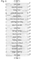
- Figure 10 is a process flow chart showing certain steps of a method of countersinking the further hole 102 of the curved panel 100.
- step s80 a process for determining an additional distance, due to the curvature of the curved panel 100, that the cutting tool is to be moved through in order to countersink the further hole 102 to the desired depth is performed. This process will be described in more detail later below with reference to Figure 11 .
- a countersinking process is performed.
- the countersinking process performed at step s62 comprises performing each of the steps s2 to s36 as described above with reference to Figures 5 to 8 (with the panel 2 replaced by the curved panel 100, and the hole 4 replaced by the further hole 102).
- the step of the first end effector controller 16 determining how far the cutting tool 38 is to be moved in order to countersink the further hole 102 to the pre-determined depth uses the additional distance determined at step s80.
- the first end effector controller 16 determines how far the cutting tool 38 is to be moved along its axis 46 in order to drill, along the axis of the further hole 102 with which it is aligned, to the pre-determined depth.
- this distance to be moved by the cutting tool 38 along its axis 46 is determined using (e.g. by adding together): (i) the distance between the tip of the cutting tool 38 and the front of the pressure foot 30 when the pressure foot has not been extended from the first frame 26; (ii) the measurement by the sensor 32 of how far the pressure foot 30 has been moved; (iii) the pre-determined depth; and (iv) the additional distance determined at step s80.
- Figure 11 is a process flow chart showing certain steps of a process of for determining the additional distance, due to the curvature of the curved panel 104, that the cutting tool 38 is to be moved through in order to countersink the further hole 102 to the pre-determined depth (as performed at step s80 of the process of Figure 10 ).
- CAD Computer Aided Design
- a Computer Aided Design (CAD) model of the pressure foot 30 is created.
- the CAD model of the pressure foot 30, hereinafter referred to as the "second CAD model”, may be drawn using any conventional CAD software package.
- the second CAD model may also model the normalisation system 31.
- the first and second CAD models are used to model how the pressure foot 30 and the curved panel 100 would contact each other if the pressure foot 30 was extended from the first frame 26 until it contacted the front (convex) surface of the curved panel 100. This modelled contact is described in more detail later below with reference to Figure 12 .
- the additional distance, due to the curvature of the curved panel 100, that the cutting tool 38 is to be moved through in order to countersink the further hole 102 to the pre-determined depth is determined. This determination of the additional distance is described in more detail later below with reference to Figure 12 .
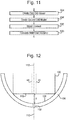
- Figure 12 is a schematic illustration (not to scale) showing the first CAD model 104 (i.e. the CAD model of the curved panel 100) and the second CAD model 106 (i.e. the CAD model of the pressure foot 30).
- the first CAD model 104 comprises a model of the further hole 102.
- the model of the further hole 102 has, for convenience and ease of understanding, been indicated in Figure 12 by the same reference numeral as the further hole 102 (i.e. the reference numeral 102).
- the second CAD model 106 comprises a model of the passage 44 in the pressure foot 30 through which the cutting tool 38 is passed during a drilling/countersinking operation.
- the model of the passage 44 has, for convenience and ease of understanding, been indicated in Figure 12 by the same reference numeral as the passage 44 (i.e. the reference numeral 44).
- the second CAD model 106 may also model the normalisation system 31 (not shown in Figure 12 for reasons of clarity).
- the convex surface 108 of the first model 104 is in contact with the front surface 110 of the second model 106.
- An axis 112 is also shown in Figure 12 .
- the axis of the further hole 102 and the axis of the passage 44 are aligned along the axis 112.
- the relative positions of the CAD models 104, 106 shown in Figure 12 are substantially the same as the actual positions that the curved panel 100 and the pressure foot 30 would have if: (i) the axis of the further hole 102 and the axis of the passage 44 were aligned with one another; and (ii) if the pressure foot 30 had been extended from the first frame 26 until it contacted the front (convex) surface of the curved panel 100.
- the modelled contact between the curved panel 100 and the pressure foot 30 (as shown in Figure 12 ) is used to determine the distance indicated in Figure 12 by a double headed arrow and the reference sign d.
- This additional distance d is the additional distance, due to the curvature of the curved panel 100, that the cutting tool 38 is to be moved through (along the axis 46) in order to countersink the further hole 102 to the pre-determined depth.
- the first model 104 was of a flat panel (e.g. the panel 2 from the first embodiment)
- the whole of the front surface 110 of the second model 106 would be in contact with the flat front surface 108 of the first model 104.
- the value of the distance d would be zero.
- the panel is curved and so the distance d is non-zero.
- the cutting tool 38 also has to be moved through the additional distance d (in addition to that distance it would have to be moved through if the panel was flat).
- the additional distance d may be measured directly from the models 104, 106.
- modelling of the panel/part to drilled, and the pressure foot advantageously tends to provide that any additional distance required to be moved by the cutting tool to drill to a desired depth may be determined.
- the above described system and method tend to provide that drilling/countersinking to a pre-determined depth into a curved (or non-flat) surface is possible.
- Apparatus including the controllers 14, 16, 18, 20, for implementing the above arrangement, and performing the method steps to be described later below, may be provided by configuring or adapting any suitable apparatus, for example one or more computers or other processing apparatus or processors, and/or providing additional modules.
- the apparatus may comprise a computer, a network of computers, or one or more processors, for implementing instructions and using data, including instructions and data in the form of a computer program or plurality of computer programs stored in or on a machine readable storage medium such as computer memory, a computer disk, ROM, PROM etc., or any combination of these or other storage media.
- the countersinking process is performed on a (flat or non-flat) panel.
- the panel is made of carbon fibre and is for fixing to a structure to form an airframe.
- the countersinking process is performed on a different type of part, e.g. a part made of one or more different types of material, or a part for a different purpose.
- the process performed on the panel/part is a countersinking process (for countersinking a predrilled hole).
- the process performed is a different type of drilling/cutting process, e.g. a process of drilling holes in a part/panel, which e.g. may be countersunk later.
- the normalisation system comprises five contact measurement devices, each of which extends to contact the front surface of the panel. Measurements from these five devices are used to calculate the normal to the surface with which to align the cutting tool.
- the normalisation system comprises a different number of contact measurement devices (e.g. three or four). The use of five contact measurement devices tends to advantageously provide a greater degree of redundancy than three or four.
- measurements of the distance between the first robot and the panel may be taken using a different type of system, e.g. a laser range sensor.
- the contact between a panel/part and the pressure foot is modelled using CAD models of the panel/part and the pressure foot.
- the contact between the part/panel and the pressure foot may be determined in a different way, e.g. using one or more different types of models of the part/panel and/or pressure foot.
Landscapes
- Engineering & Computer Science (AREA)
- Mechanical Engineering (AREA)
- Manufacturing & Machinery (AREA)
- Human Computer Interaction (AREA)
- Physics & Mathematics (AREA)
- General Physics & Mathematics (AREA)
- Automation & Control Theory (AREA)
- Robotics (AREA)
- Manipulator (AREA)
- Drilling And Boring (AREA)
- Machine Tool Sensing Apparatuses (AREA)
- Perforating, Stamping-Out Or Severing By Means Other Than Cutting (AREA)
Claims (4)
- Bohrgerät zum Versenken eines vorgebohrten Lochs (4), das in einem Teil (2, 100) gebildet ist,wobei das vorgebohrte Loch (4) von einer ersten Seite des Teils (2, 100) bis zu einer zweiten Seite des Teils(2, 100) reicht, wobei die erste Seite gegenüber der zweiten Seite liegt, wobei das Gerät Folgendes umfasst:einen ersten Roboter (10),ein erstes Element (30), das mit dem ersten Roboter (10) gekoppelt ist,ein Bohrwerkzeug (38), das mit dem ersten Roboter (10) gekoppelt ist,einen zweiten Roboter (12); undein zweites Element (52), das mit dem zweiten Roboter (12) gekoppelt ist; wobeidas Gerät angeordnet ist, um die Elemente (30, 52) gegen die gegenüberliegende erste und zweite Seite des Teils (2, 100) zu pressen, um den Teil (2, 100) zu haltenund die Ablenkung mindestens eines Abschnitts des Teils (2, 100) zu verhindern, in dem das vorgebohrte Loch (4) gebildet ist; unddas erste Element (30) und das Bohrwerkzeug (38) derart angeordnet sind, dass das Bohrwerkzeug (38) das vorgebohrte Loch (4) bis zu einer vorbestimmten Tiefe versenkt,während die Elemente (30, 52) gegen den Teil (2,100) gepresst werden, wobei die Versenkung von der Seite des Teils (2, 100) ist, gegen den durch das erste Element (30) gepresst wird, wobei das Gerät weiter Folgendes umfasst:ein Oberflächen-Messsystem (31), das konfiguriert ist, um eine Oberfläche des Teils (2, 100) an einer Vielzahl von Punkten nahe am vorgebohrten Loch (4) und dieses umgebend zu messen; undeinen Normalisierungsprozessor, der in Betrieb mit dem Oberflächen-Messsystem (31) gekoppelt ist; wobeider Normalisierungsprozessor konfiguriert ist um,unter Verwendung der Messungen der Oberfläche,eine Leistungsbetätigung durch mindestens einen Teil des Geräts zu bestimmen,die Betätigung derart ist, dass, wenn sie durch den mindestens einen Teil des Geräts durchgeführt werden sollte,das Bohrwerkzeug (38) in einem vorbestimmten Winkel mit Bezug auf die gemessene Oberfläche des Teils (2, 100) positioniert werden würde; undder mindestens eine Teil des Geräts angeordnet ist, um die Betätigung vor dem Versenken durchzuführen.
- Gerät nach Anspruch 1, wobei
das erste Element (30) mit Bezug auf das Bohrwerkzeug (38) beweglich ist; das Pressen des ersten Elements (30) gegen eine Seite des Teils (2, 100) das Bewegen des ersten Elements (30) um eine bestimmte Distanz mit Bezug auf das Bohrwerkzeug (38) umfasst; und
das Gerät weiter Folgendes umfasst:einen Sensor (32), der konfiguriert ist, um die bestimmte Distanz,bewegt vom ersten Element (30), mit Bezug auf das Bohrwerkzeug (38) zu messen; undeinen Prozessor, der in Betrieb mit dem Sensor (32) gekoppelt und konfiguriert ist,um, unter Verwendung der Sensormessung, eine Distanz zu bestimmen, um vom Bohrwerkzeug (38) bewegt zu werden, um das vorgebohrte Loch (4) bis zur vorbestimmten Tiefe zu versenken. - Bohrverfahren, umein vorgebohrtes Loch (4) zu versenken, das in einem Teil (2, 100) gebildet ist, wobei das vorgebohrte Loch (4) von einer ersten Seite des Teils (2, 100) bis zu einer zweiten Seite des Teils (2, 100) reicht, wobei die erste Seite gegenüber der zweiten Seite liegt, wobei das Verfahren Folgendes umfasst:Bereitstellen eines ersten Roboters (10),Bereitstellen eines ersten Elements (30), das mit dem ersten Roboter (10) gekoppelt ist,Bereitstellen eines Bohrwerkzeugs (38), das mit dem ersten Roboter (10) gekoppelt ist;Bereitstellen eines zweiten Roboters (12);Bereitstellen eines zweites Elements (52), das mit dem zweiten Roboter (12) gekoppelt ist;Pressen der Elemente (30, 52) gegen die gegenüberliegende erste und zweite Seite des Teils (2, 100), um den Teil (2, 100) zu halten und eine Ablenkung mindestens eines Abschnitts des Teils (2, 100) zu verhindern, in dem das vorgebohrte Loch (4) gebildet ist;Messen, durch ein Oberflächen-Messsystem (31), einer Oberfläche des Teils (2, 100) an einer Vielzahl von Punkten nahe am vorgebohrten Loch (4) und dieses umgebend; undunter Verwendung der Messungen der Oberfläche, Bestimmen, durch einen Normalisierungsprozessor, der in Betrieb mit dem Oberflächen-Messsystem (31) gekoppelt ist,eine Leistungsbetätigung durch mindestens einen Teil des Geräts, wobei die Betätigung derart ist, dass, wenn sie durch den mindestens einen Teil des Geräts durchgeführt werden würde, das Bohrwerkzeug (38) in einem bestimmten Winkel mit Bezug auf die gemessene Oberfläche des Teils (2, 100) positioniert wäre;Durchführen, durch den mindestens einen Teil des Geräts,der Betätigung, um das Bohrwerkzeug (38) in dem vorbestimmten Winkel mit Bezug auf die gemessene Oberfläche des Teils (2, 100) zu positionieren; unddanach Versenken, mit dem Bohrwerkzeug (38), des vorgebohrten Lochs (4) bis zu einer vorbestimmten Tiefe, während die Elemente (30, 52) gegen den Teil (2, 100) gepresst werden, wobei die Versenkung von der Seite des Teils (2, 100) ist,gegen den durch das erste Element (30) gepresst wird.
- Verfahren nach Anspruch 3, wobei
das erste Element (30) mit Bezug auf das Bohrwerkzeug (38) beweglich ist; das Pressen des ersten Elements (30) gegen eine Seite des Teils (2, 100) das Bewegen des ersten Elements (30) um eine bestimmte Distanz mit Bezug auf das Bohrwerkzeug (38) umfasst; und
das Verfahren weiter Folgendes umfasst:Messen der bestimmten Distanz, bewegt vom ersten Element (30) mit Bezug auf das Bohrwerkzeug (38); undunter Verwendung der Messung der bestimmten Distanz, Bestimmen eine Distanz, um vom Bohrwerkzeug (38) bewegt zu werden, um das vorgebohrte Loch (4) bis zur vorbestimmten Tiefe zu versenken.
Priority Applications (1)
| Application Number | Priority Date | Filing Date | Title |
|---|---|---|---|
| EP15168074.1A EP2927765B1 (de) | 2012-02-01 | 2013-01-29 | Bohrvorrichtung und -verfahren |
Applications Claiming Priority (2)
| Application Number | Priority Date | Filing Date | Title |
|---|---|---|---|
| GB1201745.5A GB2498977B (en) | 2012-02-01 | 2012-02-01 | Drilling apparatus and method |
| PCT/GB2013/050185 WO2013114090A1 (en) | 2012-02-01 | 2013-01-29 | Drilling apparatus and method |
Related Child Applications (2)
| Application Number | Title | Priority Date | Filing Date |
|---|---|---|---|
| EP15168074.1A Division-Into EP2927765B1 (de) | 2012-02-01 | 2013-01-29 | Bohrvorrichtung und -verfahren |
| EP15168074.1A Division EP2927765B1 (de) | 2012-02-01 | 2013-01-29 | Bohrvorrichtung und -verfahren |
Publications (2)
| Publication Number | Publication Date |
|---|---|
| EP2809485A1 EP2809485A1 (de) | 2014-12-10 |
| EP2809485B1 true EP2809485B1 (de) | 2020-05-13 |
Family
ID=45876472
Family Applications (2)
| Application Number | Title | Priority Date | Filing Date |
|---|---|---|---|
| EP15168074.1A Active EP2927765B1 (de) | 2012-02-01 | 2013-01-29 | Bohrvorrichtung und -verfahren |
| EP13703464.1A Active EP2809485B1 (de) | 2012-02-01 | 2013-01-29 | Bohrvorrichtung und -verfahren |
Family Applications Before (1)
| Application Number | Title | Priority Date | Filing Date |
|---|---|---|---|
| EP15168074.1A Active EP2927765B1 (de) | 2012-02-01 | 2013-01-29 | Bohrvorrichtung und -verfahren |
Country Status (7)
| Country | Link |
|---|---|
| US (2) | US9533359B2 (de) |
| EP (2) | EP2927765B1 (de) |
| JP (1) | JP5911976B2 (de) |
| CA (1) | CA2863444C (de) |
| ES (1) | ES2795979T3 (de) |
| GB (2) | GB2523024B8 (de) |
| WO (1) | WO2013114090A1 (de) |
Families Citing this family (32)
| Publication number | Priority date | Publication date | Assignee | Title |
|---|---|---|---|---|
| GB2523024B8 (en) | 2012-02-01 | 2016-04-20 | Bae Systems Plc | Countersinking a hole by using digital models |
| US20140005807A1 (en) * | 2012-06-29 | 2014-01-02 | Black & Decker Inc. | System for Enhancing Operation of Power Tools |
| US9481028B2 (en) * | 2013-09-26 | 2016-11-01 | The Boeing Company | Automated drilling through pilot holes |
| US10017277B2 (en) | 2014-04-30 | 2018-07-10 | The Boeing Company | Apparatus, system, and method for supporting a wing assembly |
| US10427254B2 (en) | 2014-04-30 | 2019-10-01 | The Boeing Company | Flexible manufacturing for aircraft structures |
| US9776330B2 (en) | 2014-04-30 | 2017-10-03 | The Boeing Company | Crawler robot and supporting platform |
| US9708079B2 (en) | 2014-04-30 | 2017-07-18 | The Boeing Company | Mobile automated overhead assembly tool for aircraft structures |
| US10118714B2 (en) * | 2014-04-30 | 2018-11-06 | The Boeing Company | System and method for positioning an automated assembly tool relative to a structure |
| US10000298B2 (en) | 2014-04-30 | 2018-06-19 | The Boeing Company | Metrology system for positioning assemblies |
| US9486917B2 (en) | 2014-04-30 | 2016-11-08 | The Boeing Company | Mobile automated assembly tool for aircraft structures |
| US10691097B2 (en) * | 2014-05-09 | 2020-06-23 | The Boeing Company | Path repeatable machining for full sized determinant assembly |
| EP3045989B1 (de) * | 2015-01-16 | 2019-08-07 | Comau S.p.A. | Nietvorrichtung |
| CN104759656B (zh) * | 2015-03-31 | 2017-06-27 | 武汉大学 | 一种全自动柔性双面双轴数控钻镗床 |
| EP3088137A1 (de) * | 2015-04-30 | 2016-11-02 | BAE SYSTEMS plc | Roboterarm-endeffektor zum bohren von flugzeugplatten |
| WO2016174443A1 (en) * | 2015-04-30 | 2016-11-03 | Bae Systems Plc | Robotic arm end effector for drilling aircraft panels |
| WO2016174445A1 (en) * | 2015-04-30 | 2016-11-03 | Bae Systems Plc | Drilling apparatus for drilling aircraft panels |
| GB2537920B (en) * | 2015-04-30 | 2020-11-25 | Bae Systems Plc | Drilling apparatus |
| EP3088138A1 (de) * | 2015-04-30 | 2016-11-02 | BAE SYSTEMS plc | Bohrvorrichtung zum bohren von flugzeugplatten |
| JP6806023B2 (ja) | 2017-09-29 | 2020-12-23 | 日亜化学工業株式会社 | 発光装置 |
| CN107598060B (zh) * | 2017-10-16 | 2023-07-04 | 重庆交通大学 | 飞机壁板组装立式工装辅助装置 |
| EP3814229B1 (de) | 2018-06-28 | 2022-10-12 | BAE SYSTEMS plc | Verfahren und vorrichtung zur herstellung mindestens eines teils eines flugzeugflugwerks |
| DE202018104875U1 (de) * | 2018-08-24 | 2018-10-19 | Haimer Gmbh | Schrumpfgerät mit Futtererkennung und automatischer Spulenverstellung |
| US11072439B2 (en) | 2018-09-07 | 2021-07-27 | The Boeing Company | Mobile fixture apparatuses and methods |
| US10782696B2 (en) | 2018-09-07 | 2020-09-22 | The Boeing Company | Mobile fixture apparatuses and methods |
| US10472095B1 (en) | 2018-09-07 | 2019-11-12 | The Boeing Company | Mobile fixture apparatuses and methods |
| CN109396496B (zh) * | 2018-12-12 | 2021-04-09 | 中国航空制造技术研究院 | 一种用于曲面类表面自动钻锪的锪窝深度控制方法 |
| CN111745177A (zh) * | 2019-03-29 | 2020-10-09 | 日本碍子株式会社 | 圆柱状工件的开孔装置及其开孔方法、圆柱状产品的制造方法以及圆柱状工件的检查方法 |
| GB2585474B (en) | 2019-05-23 | 2022-02-16 | Bae Systems Plc | A method and apparatus for producing at least part of a structural frame of a vehicle |
| FR3115592B1 (fr) | 2020-10-23 | 2023-07-21 | Lisi Aerospace | Procédé de palpage d’une surface courbe pour déterminer une profondeur de perçage corrigée |
| EP4316736A1 (de) * | 2022-08-01 | 2024-02-07 | Hilti Aktiengesellschaft | Verfahren zum steuern und regeln einer werkzeugmaschine und erfassungsvorringung sowie system zur durchführung des verfahrens |
| CN116038422A (zh) * | 2023-03-10 | 2023-05-02 | 成都九系机器人科技有限公司 | 一种锪窝深度精确控制方法 |
| US20250123168A1 (en) * | 2023-10-11 | 2025-04-17 | The Boeing Company | Systems and methods for identifying mis-aligned holes in structural components |
Family Cites Families (15)
| Publication number | Priority date | Publication date | Assignee | Title |
|---|---|---|---|---|
| US4885836A (en) * | 1988-04-19 | 1989-12-12 | Imta | Riveting process and apparatus |
| FR2647696B1 (fr) * | 1989-06-06 | 1991-09-27 | Dassault Avions | Ensemble d'outillage pour rivetage de pieces |
| IT1247590B (it) * | 1990-08-09 | 1994-12-28 | Jobs Spa | Metodo per l'assemblaggio di strutture, in particolare strutture aeronautiche. |
| US5231747A (en) * | 1990-12-21 | 1993-08-03 | The Boeing Company | Drill/rivet device |
| US5482409A (en) * | 1993-01-06 | 1996-01-09 | The Boeing Company | Part positioning and drilling end effector |
| JP2502909B2 (ja) * | 1993-04-14 | 1996-05-29 | ユーエイチティー株式会社 | 穿孔装置 |
| JP2625078B2 (ja) * | 1994-03-29 | 1997-06-25 | 栄電子工業株式会社 | 基板材料の小径穴加工方法及び装置 |
| JPH10249618A (ja) * | 1997-03-11 | 1998-09-22 | Nissan Shatai Co Ltd | 穿孔方法及び穿孔装置 |
| US6550118B2 (en) * | 2001-02-02 | 2003-04-22 | Electroimpact, Inc. | Apparatus and method for accurate countersinking and rivet shaving for mechanical assembly operations |
| US6922599B2 (en) * | 2001-08-13 | 2005-07-26 | The Boeing Company | System and method for producing an assembly by directly implementing three-dimensional computer-aided design component definitions |
| US6905291B2 (en) * | 2002-05-30 | 2005-06-14 | The Boeing Company | Apparatus and method for drilling holes and optionally inserting fasteners |
| ITTO20060581A1 (it) * | 2006-08-04 | 2008-02-05 | Bruno Bisiach | Dispositivo e metodo di lavorazione di un pezzo da lavorare, quale per esempio una struttura a guscio di un velivolo |
| US8301302B2 (en) * | 2008-05-08 | 2012-10-30 | The Boeing Company | Synchronous robotic operation on a structure having a confined space |
| DE202008014886U1 (de) * | 2008-11-10 | 2010-04-01 | Kuka Systems Gmbh | Fügeeinrichtung |
| GB2523024B8 (en) | 2012-02-01 | 2016-04-20 | Bae Systems Plc | Countersinking a hole by using digital models |
-
2012
- 2012-02-01 GB GB1508546.7A patent/GB2523024B8/en active Active
- 2012-02-01 GB GB1201745.5A patent/GB2498977B/en active Active
-
2013
- 2013-01-29 JP JP2014555305A patent/JP5911976B2/ja active Active
- 2013-01-29 WO PCT/GB2013/050185 patent/WO2013114090A1/en not_active Ceased
- 2013-01-29 US US14/375,979 patent/US9533359B2/en active Active
- 2013-01-29 EP EP15168074.1A patent/EP2927765B1/de active Active
- 2013-01-29 ES ES13703464T patent/ES2795979T3/es active Active
- 2013-01-29 CA CA2863444A patent/CA2863444C/en active Active
- 2013-01-29 EP EP13703464.1A patent/EP2809485B1/de active Active
-
2016
- 2016-10-27 US US15/335,729 patent/US10092961B2/en active Active
Non-Patent Citations (1)
| Title |
|---|
| None * |
Also Published As
| Publication number | Publication date |
|---|---|
| GB2498977B (en) | 2015-10-07 |
| GB2498977A (en) | 2013-08-07 |
| US10092961B2 (en) | 2018-10-09 |
| AU2013214027A1 (en) | 2014-08-21 |
| GB201508546D0 (en) | 2015-07-01 |
| GB2523024B (en) | 2016-02-17 |
| CA2863444C (en) | 2017-04-04 |
| JP5911976B2 (ja) | 2016-04-27 |
| US9533359B2 (en) | 2017-01-03 |
| AU2013214027B2 (en) | 2016-07-14 |
| JP2015510455A (ja) | 2015-04-09 |
| EP2809485A1 (de) | 2014-12-10 |
| EP2927765B1 (de) | 2021-03-10 |
| GB2523024A (en) | 2015-08-12 |
| WO2013114090A1 (en) | 2013-08-08 |
| GB201201745D0 (en) | 2012-03-14 |
| GB2523024B8 (en) | 2016-04-20 |
| GB2523024A8 (en) | 2016-04-20 |
| EP2927765A1 (de) | 2015-10-07 |
| ES2795979T3 (es) | 2020-11-25 |
| US20150023748A1 (en) | 2015-01-22 |
| US20170043414A1 (en) | 2017-02-16 |
| CA2863444A1 (en) | 2013-08-08 |
Similar Documents
| Publication | Publication Date | Title |
|---|---|---|
| EP2809485B1 (de) | Bohrvorrichtung und -verfahren | |
| EP3288711B1 (de) | Inspektion von perforierten merkmalen in gegenständen | |
| US10076843B2 (en) | Teaching apparatus for robot provided with guide part for determining position and posture of end effector | |
| US11504818B2 (en) | Machine tool, processing system, and fitting determination method of pull stud | |
| WO2016174445A1 (en) | Drilling apparatus for drilling aircraft panels | |
| KR20170106394A (ko) | 피스에 대한 리벳팅 작동 장치의 위치를 체크 및 수정하기 위한 장치를 포함하는 피스에 리벳을 적용하기 위한 장치 | |
| EP3088137A1 (de) | Roboterarm-endeffektor zum bohren von flugzeugplatten | |
| WO2016174443A1 (en) | Robotic arm end effector for drilling aircraft panels | |
| AU2013214027B9 (en) | Drilling apparatus and method | |
| JP4986880B2 (ja) | マイクロマシンやマイクロフライスマシンの工具長補正方法 | |
| JP5072743B2 (ja) | マイクロマシンおよびマイクロフライスマシン | |
| EP3088129A1 (de) | Inspektion von perforierten merkmalen in gegenständen | |
| GB2537920A (en) | Drilling apparatus | |
| EP3088138A1 (de) | Bohrvorrichtung zum bohren von flugzeugplatten | |
| GB2537919A (en) | Inspection of drilled features in objects | |
| JP4014939B2 (ja) | 工具取付位置の測定装置 | |
| JP6752032B2 (ja) | アクチュエータの可動部材の位置検出装置 | |
| CN223084307U (zh) | 一种复合机器人自动换刀设备 | |
| JP2005028432A (ja) | 板材加工機における板材寸法測定方法およびワーククランプ位置決定方法並びにその方法に用いるワーククランプ装置 | |
| JP2007253286A (ja) | ワーク加工装置および加工方法 |
Legal Events
| Date | Code | Title | Description |
|---|---|---|---|
| PUAI | Public reference made under article 153(3) epc to a published international application that has entered the european phase |
Free format text: ORIGINAL CODE: 0009012 |
|
| 17P | Request for examination filed |
Effective date: 20140828 |
|
| AK | Designated contracting states |
Kind code of ref document: A1 Designated state(s): AL AT BE BG CH CY CZ DE DK EE ES FI FR GB GR HR HU IE IS IT LI LT LU LV MC MK MT NL NO PL PT RO RS SE SI SK SM TR |
|
| AX | Request for extension of the european patent |
Extension state: BA ME |
|
| DAX | Request for extension of the european patent (deleted) | ||
| STAA | Information on the status of an ep patent application or granted ep patent |
Free format text: STATUS: EXAMINATION IS IN PROGRESS |
|
| 17Q | First examination report despatched |
Effective date: 20190409 |
|
| GRAP | Despatch of communication of intention to grant a patent |
Free format text: ORIGINAL CODE: EPIDOSNIGR1 |
|
| STAA | Information on the status of an ep patent application or granted ep patent |
Free format text: STATUS: GRANT OF PATENT IS INTENDED |
|
| INTG | Intention to grant announced |
Effective date: 20200205 |
|
| GRAS | Grant fee paid |
Free format text: ORIGINAL CODE: EPIDOSNIGR3 |
|
| GRAA | (expected) grant |
Free format text: ORIGINAL CODE: 0009210 |
|
| STAA | Information on the status of an ep patent application or granted ep patent |
Free format text: STATUS: THE PATENT HAS BEEN GRANTED |
|
| RBV | Designated contracting states (corrected) |
Designated state(s): AL AT BE BG CH CY CZ DE DK EE ES FI FR GR HR HU IE IS IT LI LT LU LV MC MK MT NL NO PL PT RO RS SE SI SK SM TR |
|
| AK | Designated contracting states |
Kind code of ref document: B1 Designated state(s): AL AT BE BG CH CY CZ DE DK EE ES FI FR GR HR HU IE IS IT LI LT LU LV MC MK MT NL NO PL PT RO RS SE SI SK SM TR |
|
| REG | Reference to a national code |
Ref country code: CH Ref legal event code: EP |
|
| REG | Reference to a national code |
Ref country code: DE Ref legal event code: R096 Ref document number: 602013069036 Country of ref document: DE |
|
| REG | Reference to a national code |
Ref country code: AT Ref legal event code: REF Ref document number: 1269652 Country of ref document: AT Kind code of ref document: T Effective date: 20200615 |
|
| REG | Reference to a national code |
Ref country code: SE Ref legal event code: TRGR |
|
| REG | Reference to a national code |
Ref country code: LT Ref legal event code: MG4D |
|
| REG | Reference to a national code |
Ref country code: NL Ref legal event code: MP Effective date: 20200513 |
|
| PG25 | Lapsed in a contracting state [announced via postgrant information from national office to epo] |
Ref country code: GR Free format text: LAPSE BECAUSE OF FAILURE TO SUBMIT A TRANSLATION OF THE DESCRIPTION OR TO PAY THE FEE WITHIN THE PRESCRIBED TIME-LIMIT Effective date: 20200814 Ref country code: IS Free format text: LAPSE BECAUSE OF FAILURE TO SUBMIT A TRANSLATION OF THE DESCRIPTION OR TO PAY THE FEE WITHIN THE PRESCRIBED TIME-LIMIT Effective date: 20200913 Ref country code: PT Free format text: LAPSE BECAUSE OF FAILURE TO SUBMIT A TRANSLATION OF THE DESCRIPTION OR TO PAY THE FEE WITHIN THE PRESCRIBED TIME-LIMIT Effective date: 20200914 Ref country code: FI Free format text: LAPSE BECAUSE OF FAILURE TO SUBMIT A TRANSLATION OF THE DESCRIPTION OR TO PAY THE FEE WITHIN THE PRESCRIBED TIME-LIMIT Effective date: 20200513 Ref country code: NO Free format text: LAPSE BECAUSE OF FAILURE TO SUBMIT A TRANSLATION OF THE DESCRIPTION OR TO PAY THE FEE WITHIN THE PRESCRIBED TIME-LIMIT Effective date: 20200813 Ref country code: LT Free format text: LAPSE BECAUSE OF FAILURE TO SUBMIT A TRANSLATION OF THE DESCRIPTION OR TO PAY THE FEE WITHIN THE PRESCRIBED TIME-LIMIT Effective date: 20200513 |
|
| REG | Reference to a national code |
Ref country code: ES Ref legal event code: FG2A Ref document number: 2795979 Country of ref document: ES Kind code of ref document: T3 Effective date: 20201125 |
|
| PG25 | Lapsed in a contracting state [announced via postgrant information from national office to epo] |
Ref country code: BG Free format text: LAPSE BECAUSE OF FAILURE TO SUBMIT A TRANSLATION OF THE DESCRIPTION OR TO PAY THE FEE WITHIN THE PRESCRIBED TIME-LIMIT Effective date: 20200813 Ref country code: LV Free format text: LAPSE BECAUSE OF FAILURE TO SUBMIT A TRANSLATION OF THE DESCRIPTION OR TO PAY THE FEE WITHIN THE PRESCRIBED TIME-LIMIT Effective date: 20200513 Ref country code: RS Free format text: LAPSE BECAUSE OF FAILURE TO SUBMIT A TRANSLATION OF THE DESCRIPTION OR TO PAY THE FEE WITHIN THE PRESCRIBED TIME-LIMIT Effective date: 20200513 Ref country code: HR Free format text: LAPSE BECAUSE OF FAILURE TO SUBMIT A TRANSLATION OF THE DESCRIPTION OR TO PAY THE FEE WITHIN THE PRESCRIBED TIME-LIMIT Effective date: 20200513 |
|
| REG | Reference to a national code |
Ref country code: AT Ref legal event code: MK05 Ref document number: 1269652 Country of ref document: AT Kind code of ref document: T Effective date: 20200513 |
|
| PG25 | Lapsed in a contracting state [announced via postgrant information from national office to epo] |
Ref country code: AL Free format text: LAPSE BECAUSE OF FAILURE TO SUBMIT A TRANSLATION OF THE DESCRIPTION OR TO PAY THE FEE WITHIN THE PRESCRIBED TIME-LIMIT Effective date: 20200513 Ref country code: NL Free format text: LAPSE BECAUSE OF FAILURE TO SUBMIT A TRANSLATION OF THE DESCRIPTION OR TO PAY THE FEE WITHIN THE PRESCRIBED TIME-LIMIT Effective date: 20200513 |
|
| PG25 | Lapsed in a contracting state [announced via postgrant information from national office to epo] |
Ref country code: SM Free format text: LAPSE BECAUSE OF FAILURE TO SUBMIT A TRANSLATION OF THE DESCRIPTION OR TO PAY THE FEE WITHIN THE PRESCRIBED TIME-LIMIT Effective date: 20200513 Ref country code: EE Free format text: LAPSE BECAUSE OF FAILURE TO SUBMIT A TRANSLATION OF THE DESCRIPTION OR TO PAY THE FEE WITHIN THE PRESCRIBED TIME-LIMIT Effective date: 20200513 Ref country code: AT Free format text: LAPSE BECAUSE OF FAILURE TO SUBMIT A TRANSLATION OF THE DESCRIPTION OR TO PAY THE FEE WITHIN THE PRESCRIBED TIME-LIMIT Effective date: 20200513 Ref country code: DK Free format text: LAPSE BECAUSE OF FAILURE TO SUBMIT A TRANSLATION OF THE DESCRIPTION OR TO PAY THE FEE WITHIN THE PRESCRIBED TIME-LIMIT Effective date: 20200513 Ref country code: RO Free format text: LAPSE BECAUSE OF FAILURE TO SUBMIT A TRANSLATION OF THE DESCRIPTION OR TO PAY THE FEE WITHIN THE PRESCRIBED TIME-LIMIT Effective date: 20200513 Ref country code: CZ Free format text: LAPSE BECAUSE OF FAILURE TO SUBMIT A TRANSLATION OF THE DESCRIPTION OR TO PAY THE FEE WITHIN THE PRESCRIBED TIME-LIMIT Effective date: 20200513 |
|
| REG | Reference to a national code |
Ref country code: DE Ref legal event code: R097 Ref document number: 602013069036 Country of ref document: DE |
|
| PG25 | Lapsed in a contracting state [announced via postgrant information from national office to epo] |
Ref country code: PL Free format text: LAPSE BECAUSE OF FAILURE TO SUBMIT A TRANSLATION OF THE DESCRIPTION OR TO PAY THE FEE WITHIN THE PRESCRIBED TIME-LIMIT Effective date: 20200513 Ref country code: SK Free format text: LAPSE BECAUSE OF FAILURE TO SUBMIT A TRANSLATION OF THE DESCRIPTION OR TO PAY THE FEE WITHIN THE PRESCRIBED TIME-LIMIT Effective date: 20200513 |
|
| PLBE | No opposition filed within time limit |
Free format text: ORIGINAL CODE: 0009261 |
|
| STAA | Information on the status of an ep patent application or granted ep patent |
Free format text: STATUS: NO OPPOSITION FILED WITHIN TIME LIMIT |
|
| 26N | No opposition filed |
Effective date: 20210216 |
|
| PG25 | Lapsed in a contracting state [announced via postgrant information from national office to epo] |
Ref country code: SI Free format text: LAPSE BECAUSE OF FAILURE TO SUBMIT A TRANSLATION OF THE DESCRIPTION OR TO PAY THE FEE WITHIN THE PRESCRIBED TIME-LIMIT Effective date: 20200513 |
|
| PG25 | Lapsed in a contracting state [announced via postgrant information from national office to epo] |
Ref country code: MC Free format text: LAPSE BECAUSE OF FAILURE TO SUBMIT A TRANSLATION OF THE DESCRIPTION OR TO PAY THE FEE WITHIN THE PRESCRIBED TIME-LIMIT Effective date: 20200513 |
|
| REG | Reference to a national code |
Ref country code: CH Ref legal event code: PL |
|
| PG25 | Lapsed in a contracting state [announced via postgrant information from national office to epo] |
Ref country code: LU Free format text: LAPSE BECAUSE OF NON-PAYMENT OF DUE FEES Effective date: 20210129 |
|
| REG | Reference to a national code |
Ref country code: BE Ref legal event code: MM Effective date: 20210131 |
|
| PG25 | Lapsed in a contracting state [announced via postgrant information from national office to epo] |
Ref country code: LI Free format text: LAPSE BECAUSE OF NON-PAYMENT OF DUE FEES Effective date: 20210131 Ref country code: CH Free format text: LAPSE BECAUSE OF NON-PAYMENT OF DUE FEES Effective date: 20210131 |
|
| PG25 | Lapsed in a contracting state [announced via postgrant information from national office to epo] |
Ref country code: IE Free format text: LAPSE BECAUSE OF NON-PAYMENT OF DUE FEES Effective date: 20210129 |
|
| PG25 | Lapsed in a contracting state [announced via postgrant information from national office to epo] |
Ref country code: BE Free format text: LAPSE BECAUSE OF NON-PAYMENT OF DUE FEES Effective date: 20210131 |
|
| PG25 | Lapsed in a contracting state [announced via postgrant information from national office to epo] |
Ref country code: HU Free format text: LAPSE BECAUSE OF FAILURE TO SUBMIT A TRANSLATION OF THE DESCRIPTION OR TO PAY THE FEE WITHIN THE PRESCRIBED TIME-LIMIT; INVALID AB INITIO Effective date: 20130129 |
|
| PG25 | Lapsed in a contracting state [announced via postgrant information from national office to epo] |
Ref country code: CY Free format text: LAPSE BECAUSE OF FAILURE TO SUBMIT A TRANSLATION OF THE DESCRIPTION OR TO PAY THE FEE WITHIN THE PRESCRIBED TIME-LIMIT Effective date: 20200513 |
|
| PG25 | Lapsed in a contracting state [announced via postgrant information from national office to epo] |
Ref country code: MK Free format text: LAPSE BECAUSE OF FAILURE TO SUBMIT A TRANSLATION OF THE DESCRIPTION OR TO PAY THE FEE WITHIN THE PRESCRIBED TIME-LIMIT Effective date: 20200513 |
|
| PG25 | Lapsed in a contracting state [announced via postgrant information from national office to epo] |
Ref country code: MT Free format text: LAPSE BECAUSE OF FAILURE TO SUBMIT A TRANSLATION OF THE DESCRIPTION OR TO PAY THE FEE WITHIN THE PRESCRIBED TIME-LIMIT Effective date: 20200513 |
|
| PGFP | Annual fee paid to national office [announced via postgrant information from national office to epo] |
Ref country code: DE Payment date: 20241218 Year of fee payment: 13 |
|
| PGFP | Annual fee paid to national office [announced via postgrant information from national office to epo] |
Ref country code: ES Payment date: 20250203 Year of fee payment: 13 |
|
| PGFP | Annual fee paid to national office [announced via postgrant information from national office to epo] |
Ref country code: IT Payment date: 20250107 Year of fee payment: 13 |
|
| PGFP | Annual fee paid to national office [announced via postgrant information from national office to epo] |
Ref country code: TR Payment date: 20250103 Year of fee payment: 13 |
|
| PGFP | Annual fee paid to national office [announced via postgrant information from national office to epo] |
Ref country code: FR Payment date: 20251217 Year of fee payment: 14 |
|
| PGFP | Annual fee paid to national office [announced via postgrant information from national office to epo] |
Ref country code: SE Payment date: 20251217 Year of fee payment: 14 |