EP2809449B1 - Zentrifugierungssystem und entsprechendes verfahren - Google Patents
Zentrifugierungssystem und entsprechendes verfahren Download PDFInfo
- Publication number
- EP2809449B1 EP2809449B1 EP13744297.6A EP13744297A EP2809449B1 EP 2809449 B1 EP2809449 B1 EP 2809449B1 EP 13744297 A EP13744297 A EP 13744297A EP 2809449 B1 EP2809449 B1 EP 2809449B1
- Authority
- EP
- European Patent Office
- Prior art keywords
- container
- liquid
- vessel
- motive device
- solids
- Prior art date
- Legal status (The legal status is an assumption and is not a legal conclusion. Google has not performed a legal analysis and makes no representation as to the accuracy of the status listed.)
- Active
Links
- 238000005119 centrifugation Methods 0.000 title claims description 21
- 238000000034 method Methods 0.000 title description 11
- 239000007788 liquid Substances 0.000 claims description 51
- 239000007787 solid Substances 0.000 claims description 25
- 230000008878 coupling Effects 0.000 claims description 19
- 238000010168 coupling process Methods 0.000 claims description 19
- 238000005859 coupling reaction Methods 0.000 claims description 19
- 238000000605 extraction Methods 0.000 claims description 12
- 239000002887 superconductor Substances 0.000 claims description 9
- 239000000463 material Substances 0.000 claims description 6
- 230000003068 static effect Effects 0.000 claims description 3
- 239000012530 fluid Substances 0.000 description 7
- 238000005339 levitation Methods 0.000 description 7
- 238000000926 separation method Methods 0.000 description 6
- 238000010586 diagram Methods 0.000 description 4
- 239000011159 matrix material Substances 0.000 description 4
- 238000011084 recovery Methods 0.000 description 4
- 238000012986 modification Methods 0.000 description 3
- 230000004048 modification Effects 0.000 description 3
- 239000000725 suspension Substances 0.000 description 3
- -1 for example Polymers 0.000 description 2
- 239000004033 plastic Substances 0.000 description 2
- 229920003023 plastic Polymers 0.000 description 2
- 230000008569 process Effects 0.000 description 2
- 102000004190 Enzymes Human genes 0.000 description 1
- 108090000790 Enzymes Proteins 0.000 description 1
- 239000004743 Polypropylene Substances 0.000 description 1
- 230000008901 benefit Effects 0.000 description 1
- 239000013060 biological fluid Substances 0.000 description 1
- 239000008280 blood Substances 0.000 description 1
- 210000004369 blood Anatomy 0.000 description 1
- 239000007853 buffer solution Substances 0.000 description 1
- 238000004113 cell culture Methods 0.000 description 1
- 239000006285 cell suspension Substances 0.000 description 1
- 238000004140 cleaning Methods 0.000 description 1
- 238000012864 cross contamination Methods 0.000 description 1
- 230000006378 damage Effects 0.000 description 1
- 230000002939 deleterious effect Effects 0.000 description 1
- 238000007599 discharging Methods 0.000 description 1
- 238000001914 filtration Methods 0.000 description 1
- 229920001903 high density polyethylene Polymers 0.000 description 1
- 239000004700 high-density polyethylene Substances 0.000 description 1
- 230000036512 infertility Effects 0.000 description 1
- 239000002184 metal Substances 0.000 description 1
- 239000002245 particle Substances 0.000 description 1
- 230000010287 polarization Effects 0.000 description 1
- 229920000642 polymer Polymers 0.000 description 1
- 229920001155 polypropylene Polymers 0.000 description 1
- 238000004064 recycling Methods 0.000 description 1
- 238000005096 rolling process Methods 0.000 description 1
- 239000000243 solution Substances 0.000 description 1
- 239000006228 supernatant Substances 0.000 description 1
- 230000001360 synchronised effect Effects 0.000 description 1
- 230000007704 transition Effects 0.000 description 1
- 238000005406 washing Methods 0.000 description 1
- 229910021521 yttrium barium copper oxide Inorganic materials 0.000 description 1
Images


Classifications
-
- B—PERFORMING OPERATIONS; TRANSPORTING
- B04—CENTRIFUGAL APPARATUS OR MACHINES FOR CARRYING-OUT PHYSICAL OR CHEMICAL PROCESSES
- B04B—CENTRIFUGES
- B04B1/00—Centrifuges with rotary bowls provided with solid jackets for separating predominantly liquid mixtures with or without solid particles
- B04B1/02—Centrifuges with rotary bowls provided with solid jackets for separating predominantly liquid mixtures with or without solid particles without inserted separating walls
-
- B—PERFORMING OPERATIONS; TRANSPORTING
- B04—CENTRIFUGAL APPARATUS OR MACHINES FOR CARRYING-OUT PHYSICAL OR CHEMICAL PROCESSES
- B04B—CENTRIFUGES
- B04B1/00—Centrifuges with rotary bowls provided with solid jackets for separating predominantly liquid mixtures with or without solid particles
- B04B1/04—Centrifuges with rotary bowls provided with solid jackets for separating predominantly liquid mixtures with or without solid particles with inserted separating walls
-
- B—PERFORMING OPERATIONS; TRANSPORTING
- B04—CENTRIFUGAL APPARATUS OR MACHINES FOR CARRYING-OUT PHYSICAL OR CHEMICAL PROCESSES
- B04B—CENTRIFUGES
- B04B11/00—Feeding, charging, or discharging bowls
- B04B11/04—Periodical feeding or discharging; Control arrangements therefor
-
- B—PERFORMING OPERATIONS; TRANSPORTING
- B04—CENTRIFUGAL APPARATUS OR MACHINES FOR CARRYING-OUT PHYSICAL OR CHEMICAL PROCESSES
- B04B—CENTRIFUGES
- B04B11/00—Feeding, charging, or discharging bowls
- B04B11/08—Skimmers or scrapers for discharging ; Regulating thereof
- B04B11/082—Skimmers for discharging liquid
-
- B—PERFORMING OPERATIONS; TRANSPORTING
- B04—CENTRIFUGAL APPARATUS OR MACHINES FOR CARRYING-OUT PHYSICAL OR CHEMICAL PROCESSES
- B04B—CENTRIFUGES
- B04B5/00—Other centrifuges
- B04B5/04—Radial chamber apparatus for separating predominantly liquid mixtures, e.g. butyrometers
- B04B5/0442—Radial chamber apparatus for separating predominantly liquid mixtures, e.g. butyrometers with means for adding or withdrawing liquid substances during the centrifugation, e.g. continuous centrifugation
-
- B—PERFORMING OPERATIONS; TRANSPORTING
- B04—CENTRIFUGAL APPARATUS OR MACHINES FOR CARRYING-OUT PHYSICAL OR CHEMICAL PROCESSES
- B04B—CENTRIFUGES
- B04B7/00—Elements of centrifuges
- B04B7/08—Rotary bowls
-
- B—PERFORMING OPERATIONS; TRANSPORTING
- B04—CENTRIFUGAL APPARATUS OR MACHINES FOR CARRYING-OUT PHYSICAL OR CHEMICAL PROCESSES
- B04B—CENTRIFUGES
- B04B9/00—Drives specially designed for centrifuges; Arrangement or disposition of transmission gearing; Suspending or balancing rotary bowls
-
- B—PERFORMING OPERATIONS; TRANSPORTING
- B04—CENTRIFUGAL APPARATUS OR MACHINES FOR CARRYING-OUT PHYSICAL OR CHEMICAL PROCESSES
- B04B—CENTRIFUGES
- B04B9/00—Drives specially designed for centrifuges; Arrangement or disposition of transmission gearing; Suspending or balancing rotary bowls
- B04B9/02—Electric motor drives
- B04B9/04—Direct drive
-
- B—PERFORMING OPERATIONS; TRANSPORTING
- B04—CENTRIFUGAL APPARATUS OR MACHINES FOR CARRYING-OUT PHYSICAL OR CHEMICAL PROCESSES
- B04B—CENTRIFUGES
- B04B9/00—Drives specially designed for centrifuges; Arrangement or disposition of transmission gearing; Suspending or balancing rotary bowls
- B04B9/08—Arrangement or disposition of transmission gearing ; Couplings; Brakes
-
- B—PERFORMING OPERATIONS; TRANSPORTING
- B04—CENTRIFUGAL APPARATUS OR MACHINES FOR CARRYING-OUT PHYSICAL OR CHEMICAL PROCESSES
- B04B—CENTRIFUGES
- B04B9/00—Drives specially designed for centrifuges; Arrangement or disposition of transmission gearing; Suspending or balancing rotary bowls
- B04B9/12—Suspending rotary bowls ; Bearings; Packings for bearings
Definitions
- This disclosure relates generally to the fluid handling arts and, more particularly, to systems for separating solids, such as cells, from a liquid, using centrifugal force.
- centrifugation to separate a solid fraction, such as cells, from a liquid fraction, of a suspension
- the centrifuges used for collecting cells from a bioreactor are not disposable components, and in any case require a halting of the centrifugation process in order to allow for cell recovery.
- existing devices that attempt to achieve such semi-continuous centrifugation invariably require dynamic seals to introduce the cell suspension to and extract the supernatant from the centrifuge. This adds to the cost and complexity, risks breaching sterility, and also potentially results in the generation of heat and particles (which is deleterious in the case of autologous cell seperaration, and in many cases will necessitate a costly and time consuming added filtration step).
- These existing devices also typically rely on high flow rates and excessive g-forces, which may destroy fragile cells.
- the centrifuge may at least rotate, and possibly levitate, as well, while the process of solids recovery is completed. Also, the arrangement may be such that the capacity of the separation compartment would be minimized to allow for a high separation efficiency at a relatively low flow rate (e.g., ⁇ 1 liter/minute, and possibly as low as 0.25-0.5 milliliters/minute), even with the use of dynamic seals.
- WO 02/36266 A2 discloses a centrifugal separation device for use in a fluid separation system.
- the centrifugal separation device includes a centrifugal rotor housing and a rotor which is disposed in a freely rotatable disposition within the housing, the rotor having a fluid receiving area and several fluid flow channels defined therein.
- EP 0 930 099 A2 describes a centrifugal apparatus for biological fluids, the apparatus comprising a frame to receive a centrifugal chamber in a freely rotable manner.
- US 4,944,883A relates to a system for separating plasma rich in platelets from whole blood into a diverging centrifugation gap between inner and an outer walls of a rotor rotating about a central axis within an outer housing.
- JP S63-302 969 A proposes a centrifugal separator comprising a separating tank rotated by the diamagnetism of a superconductor in a main body.
- an apparatus for use in performing centrifugation with a liquid including solids comprises a container including an interior compartment for receiving the liquid and solids.
- the container is capable of rotating to urge the solids toward the periphery of the interior compartment.
- a fixed extraction conduit is provided for extracting at least a portion of the solids from adjacent the periphery of the interior compartment of the container.
- a motive device is also provided for forming a non-contact coupling with the container.
- the apparatus also includes a vessel for receiving the container.
- the vessel has an inlet for introducing the liquid and solids to the container and a drain for draining at least liquid from the vessel. Any one of the inlet, the extraction conduit, or the drain may comprise a tube connected to a wall of the vessel by a static
- the motive device may rotate the container via the non-contact coupling.
- the motive device may also be adapted to levitate the container via the non-contact coupling.
- the motive device may be adapted to levitate and rotate the container via the non-contact coupling.
- the motive device may comprise a magnet, a superconductor or an electromagnet.
- the container may include a bottom wall and an upstanding sidewall forming an at least partially open top.
- a lip may be provided adjacent the sidewall for assisting in retaining solids, such as cells, in the interior compartment during rotation.
- the container may comprise a rigid material, and may carry at least one magnet.
- a further aspect of this disclosure relates to an apparatus for use in performing centrifugation on a liquid including solids.
- the apparatus comprises a vessel and an open-ended container mounted for rotating within the vessel.
- the container includes an interior compartment for receiving the liquid and solids.
- a motive device is also provided for rotating the container by way of a non-contact coupling.
- the motive device comprises a superconductor connected to a motor, and the container is adapted for forming a magnetic coupling with the superconductor.
- the motive device may comprise a magnet, and the container is adapted for forming a magnetic coupling with the magnet of the motive device.
- a permanent magnet may be adapted for rotating to rotate the container via a magnetic coupling with the superconductor.
- a mechanical bearing may support the container for rotation relative to the vessel.
- the container may include a lip along an upper portion for assisting in retaining cells in the interior compartment during rotation.
- a fixed extraction conduit may also be provided for extracting at least a portion of the solid.
- the extraction conduit may be adjacent the periphery of the interior compartment of the container.
- Another aspect of this invention is an apparatus for use in performing substantially continuous centrifugation to separate cells from a liquid.
- the vessel is adapted for receiving the liquid, and a container is mounted for rotating within the vessel.
- the container includes an interior compartment for receiving the liquid, and the vessel includes an inlet for introducing the liquid to the interior compartment of the container, an extraction conduit from extracting cells from the interior compartment of the container, and a drain for draining at least liquid from the vessel.
- the arrangement may further include a motive device for rotating the container relative to the vessel.
- a motive device may also be provided for levitating the container relative to the vessel.
- the extraction conduit may comprise a partially non-linear tube in the container, which may have a substantially open top.
- a further aspect of this disclosure is an apparatus for use in performing substantially continuous centrifugation to separate cells from a liquid.
- the apparatus comprises a collapsible vessel and a container mounted for rotating within the vessel.
- the container includes an interior compartment for receiving the liquid.
- the vessel comprises a flexible bag.
- a motive device may also be provided for forming a non-contact coupling with the container.
- the liquid flow rate may be from about 250 ml/min to about 500 ml/min.
- a further aspect of the invention is an apparatus for use in performing centrifugation to separate cells from a liquid.
- the apparatus comprises a container mounted for rotation, the container including a first conduit for conveying the liquid to an interior compartment of the container and a second conduit for conveying liquid from the interior compartment, the first and second conduits each being connected to the container by way of a dynamic seal.
- a flow rate of the liquid is from about 250 ml/min to about 500 ml/min, and may be through one or more of the first conduit, the second conduit, or the interior compartment of the vessel.
- Yet another aspect of this disclosure relates to a system including a bioreactor and any of the above-described apparatuses.
- a method of centrifugation using a liquid including solids comprises rotating a container including the liquid, and during the rotating step, removing a major portion of the solids from the container.
- a method of centrifugation also comprises rotating a container including a liquid and cells, and during the rotating step, removing a major portion of the cells from the container.
- the method may further include the step of levitating the container within a vessel, and the removing step may comprise extracting the solids from adjacent the sidewalls of the container.
- the method may further include the step of conveying liquid from the container during the rotating step, which may involve overflowing a liquid fraction substantially free of cells from the container.
- Another method of centrifugation comprises rotating a container including a liquid and cells and, during the rotating step, transmitting liquid substantially free of cells from the container.
- the transmitting step may comprise overflowing the liquid from the container.
- the liquid flow rate may be from about 250 ml/min to about 500 ml/min.
- the container may have has a capacity of about 100 ml to about 300 ml, and possibly about 135 ml.
- a further method for performing centrifugation to separate cells from a liquid comprises providing a container mounted for rotation, the container including a first conduit for conveying the liquid to an interior compartment of the container and a second conduit for conveying liquid from the interior compartment, the first and second conduits each being connected to the container by way of a dynamic seal.
- the method further includes the step of flowing liquid through the container at a rate of about 250 ml/min to about 500 ml/min.
- the apparatus comprises a container including an interior compartment for receiving the liquid and solids, said container being capable of rotating, and a motive device for levitating the container.
- One of the motive device or the container comprises a magnet.
- One of the motive device or the container comprises a superconductor.
- the container may comprise an open-top bowl, and a fixed extraction conduit may extend into the container.
- a further aspect of the disclosure pertains to a centrifuge including a disposable bag for receiving the liquid and solids, and means for separating the liquid from the solids.
- the separating means may comprise a container for receiving the liquid and solids within the disposable bag, the container being coupled to a motive device (such as a motor for rotating a magnet).
- FIG. 1 illustrates a centrifugation system 10 according to the basic concepts of the disclosure.
- This system 10 includes a vessel 12 including an interior compartment for receiving a container 14 capable of moving within the compartment as the result of a non-contact coupling.
- a motive device 16 external to the vessel 12 provides the forces for achieving the movement (which as discussed herein may be a combination of levitation and rotation), and an inlet I is provided for introducing the suspension to an interior compartment of the container 14.
- An outlet O communicates with the container 14 along its periphery to recover the liquid dense with cells as the result of the centrifugal force created when the container 14 is rotated within the vessel 12.
- the separated liquid may flow out from the container 14 into the interior compartment of the vessel 12, and then be discharged through a drain D.
- a continuously operable and completely closed centrifugation system 10 thus results, without the need for dynamic seals or the like.
- the vessel 12 is this embodiment comprises a housing, which may be formed of a rigid material, such as hard plastic or metal.
- the inlet I may be provided by a tube 12a through the upper wall, such as at or near the center, and a similar tube 12b mounted closer to the periphery provides the extraction conduit, or outlet O.
- a third tube 12c along the lower portion of the vessel 12 provides the conduit for discharging the media.
- the container 14 may also comprise a rigid or semi-rigid cup or bowl-shaped structure including a bottom wall 14a and an upstanding sidewall 14b forming an at least partially open top.
- the bottom wall 14a may support or carry one or more magnets 18, which are arranged to interface with the external motive device 16.
- the arrangement may be one that provides the container 14 with levitation and rotation in the absence of a physical bearing or the like. This may be achieved by using a field-cooled superconductor 20 as forming part of the motive device 16, which when rotated may provide both the levitational and rotational force for the container 14 via the magnetic coupling or pinning with the magnets 18.
- the details may be found in one or more of U.S. Patent Nos.
- the interior compartment receives the liquid.
- the cells in this liquid are caused to move outwardly as the result of centrifugal force created by the rotation of the container 14.
- the extraction conduit formed by tube 12b is mounted adjacent to the periphery of the container 14, such as along the sidewall 14b.
- a pump (not shown) associated with the tube 12b may be used to apply a negative pressure and extract cell-rich liquid from the periphery of the container 14.
- the liquid will eventually line the vertical sides of the container 14 and may overflow from the open top.
- This liquid which should be generally free of cells, flows into the interior compartment of the surrounding vessel 12.
- This liquid may be drained from the vessel 12 through tube 12c, and may be discarded or subjected to further processing (such as by recycling it to the inlet I).
- the container 14 includes a lip along its upper portion to help contain the cell-laden liquid in the interior compartment.
- the tube 12c is shown as having a non-linear portion in the interior compartment to assist in recovering the cells that have migrated toward the inner sides of the container 14 as the result of the centrifugal force created by rotation.
- the vessel 12 including the container 14 may be discarded.
- this single-use arrangement allows for these combined structures to be made of inexpensive disposable materials, which advantageously eliminates the risk of cross-contamination and cleaning costs.
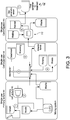
- the vessel 12 including the container 14 along with the various connections for conveying fluid may also be provided as part of a cartridge for integrating with a system including other disposable components, such as perhaps a bioreactor or like cell culture device (see Figure 3 ).
- the vessel 12 is described as being rigid or semi-rigid, it could take the form of a flexible bag 112 or the like, as shown in Figure 4 .
- the inlet 112a, outlet 112b, and drain 112c may be provided, as in the embodiment described above.
- the advantage is that the bag 112 may be folded and stored in a compact fashion prior to use, and then expanded.
- a support structure such as a rigid container C may be provided for helping to ensure that the flexible walls of the bag do not collapse or interfere with the rotation of the container 114.
- the bag 112 may also include a rigid portion 112d along all or a portion of the bottom thereof, which may further include a retainer (such as a projection or post 112e) for receiving and retaining the container 114, such as by passing through an opening in magnet 118.
- a retainer such as a projection or post 112e
- the arrangement may be such that the levitation and rotation of the container 114 via the external motive device 116 is not hampered (e.g., there is no direct engagement between the retainer 112e and container 114, yet the structures remain coupled).
- the container 114 may be arranged to be supported by a physical or mechanical bearing.
- a roller bearing 120 may be provided between the magnet 118 and the rigid portion 112d (or, alternatively, between the matrix material M and the rigid portion 112d, or with the magnet 118 or the matrix material M and the retainer 112e).
- the bearing 120 may comprise a race 120a for retaining a rolling element, such as a ball 120b, roller, or the like.
- the motive device 116 need not supply a levitative force, but may instead serve to transmit rotational torque only (and thus may comprise a rotating magnet or like structure forming a non-contact coupling through the vessel 112). Examples of such bearing arrangements may be found in U.S. Patent Application Publication No. 201001 57752 .
- a removable retaining element 122 may also be provided for retaining the container 114.
- FIG. 5 Another possible embodiment of a centrifuge system 200 is shown in Figure 5 .
- the container 204 actually includes two magnetic subsystems: a first one that serves to levitate the container 204, which includes a first magnet 206, which may be in the form of a ring, and a second magnetic subsystem that includes at least two alternating polarity driven magnets 208a, 208b, which may be positioned inside of the first, ring-shaped magnet 206, to transmit driving torque.
- Polarization of the ring magnet 206 is vertical, and the driven magnets 208a, 2086 are shown as being disk-shaped and having opposite or alternating polarities to form a magnetic coupling and transmit the torque to the levitating container 204.
- Levitation magnet 206 and driven magnets 208a, 208b may be integrated in one rigid structure such as by embedding or attaching all three to a lightweight, inert matrix material M, such as plastic or the like.
- the motive device includes a superconducting element 210 that is generally annular.
- This element 210 can be fabricated of a single unitary piece of a high-temperature superconducting material (YBCO or the like), or may be comprised of a plurality of component parts or segments.
- YBCO high-temperature superconducting material
- the superconducting ring 210 Upon being cooled to the transition temperature in the presence of a magnetic field and aligning with the ring-shaped permanent magnet 206 producing the same magnetic field, the superconducting ring 210 thus provides the combined repulsive/attractive, spring-like pinning force that levitates the container 204 in the vessel 202 in an exceptionally stable and reliable fashion.
- the vessel 202 is shown as being supported on the outer surface of a special cryostat 220 designed for use with this system 200.
- a special cryostat 220 designed for use with this system 200.
- a motive device is used to impart rotary motion to the container 204, and may be positioned adjacent to and concentric with the annular superconducting element 210.
- a motive device for use in the system 200 of this third embodiment includes driving magnets 212a, 212b that correspond to the driven magnets 208a, 208b on the container 204 and having opposite polarities to create a magnetic coupling.
- the driving magnets 212a, 212b may be coupled to a shaft 214 also forming part of the motive device.
- the driving magnets 212a, 212b may be attached directly to the shaft 214, or as illustrated in Figure 2 , may be embedded or attached to a matrix material.
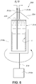
- FIG. 6 illustrates a centrifuge system 300 including a container 314 supported by a motive device 316 comprising a motor 316a and a rotating platform 316b for receiving the container 314.
- the inlet and outlet for performing the substantially continuous flow of media is provided by conduits in the form of tubes 312a, 312b, which are connected to the container 314 by dynamic seals 322, and may be connected to a static support structure, such as a cap 324.
- the arrangement thus allows for the container 314 to rotate to perform centrifugation.
- the arrangement is this embodiment may be used in connection with specific process parameters to ensure optimum efficiency (e.g., maximum cell separation with minimum destruction).
- the volume of the container may be between about 100 ml and about 300 ml, and in particular about 135 ml.
- the corresponding flow may be less than one liter per minute, and may be in the range of about 250 milliliters per minute (0.25 L/min) to about 500 milliliters per minute (0.5 ml/min).
- no extraction conduit is located in the same position as the above-described arrangements. Accordingly, the segregated cells L may be collected at the end of the centrifugation process. This recovery may be aided by using a washing step (e.g., using a trypsinisation solution comprising 1.55 L tryposin (an enzyme) to release the cells and 7.45 L of a PBS buffer solution to keep the cells alive) that have accumulated on the container walls.
- the container 314 may be a single use component (e.g., a disposable bag or liner), and thus may be discarded after cell recovery.
- various materials may be used to form the vessel in any combination, including polymers (such as, for example, polypropylene for any flexible portions, and high density polyethylene for any rigid portions).
- polymers such as, for example, polypropylene for any flexible portions, and high density polyethylene for any rigid portions.
Landscapes
- Centrifugal Separators (AREA)
- Apparatus Associated With Microorganisms And Enzymes (AREA)
- Micro-Organisms Or Cultivation Processes Thereof (AREA)
Claims (11)
- Vorrichtung zur Verwendung in der Durchführung einer Zentrifugierbehandlung einer Feststoffe enthaltenden Flüssigkeit, umfassend:einen Behälter (14) mit einem Innenabteil zum Aufnehmen der Flüssigkeit und der Feststoffe, wobei der Behälter (14) rotierbar ist, um die Feststoffe in Richtung zur Peripherie des Innenabteils zu drängen;eine feste Extraktionsleitung (O) zum Extrahieren mindestens eines Teils der Feststoffe aus der Umgebung der Peripherie des Innenabteils des Behälters (14); undeine Antriebseinrichtung (16) zum Bilden einer berührungslosen Kopplung mit dem Behälter (14),wobei die Vorrichtung ein Gefäß (12) zur Aufnahme des Behälters (14) umfasst, wobei das Gefäß (12) einen Einlass (I) zum Einführen der Flüssigkeit und der Feststoffe in den Behälter (14) und einen Auslass (D) zum Abführen von wenigstens Flüssigkeit aus dem Gefäß (12) umfasst.
- Vorrichtung nach Anspruch 1, wobei eines der Elemente Einlass (I), Extraktionsleitung (O) oder Auslass (D) ein Rohr umfasst, welches über eine statische Dichtung mit einer Wand des Gefäßes (12) verbunden ist.
- Vorrichtung nach Anspruch 1 oder 2, wobei die Antriebseinrichtung (16) dazu ausgebildet ist, den Behälter (14) über die berührungslose Kopplung rotieren zu lassen.
- Vorrichtung nach Anspruch 1 oder 2, wobei die Antriebseinrichtung (16) dazu ausgebildet ist, den Behälter (14) über die berührungslose Kopplung schweben zu lassen.
- Vorrichtung nach Anspruch 1 oder 2, wobei die Antriebseinrichtung (16) dazu ausgebildet ist, den Behälter (14) über die berührungslose Kopplung schweben und rotieren zu lassen.
- Vorrichtung nach einem der Ansprüche 1 bis 5, wobei die Antriebseinrichtung (16) einen Supraleiter umfasst.
- Vorrichtung nach einem der Ansprüche 1 bis 5, wobei die Antriebseinrichtung (16) einen Elektromagneten umfasst.
- Vorrichtung nach einem der Ansprüche 1 bis 7, wobei der Behälter (14) eine Bodenwand und eine aufrecht stehende Seitenwand umfasst, welche einen mindestens teilweise offenen oberen Teil bilden.
- Vorrichtung nach Anspruch 8, wobei der Behälter (14) eine Lippe benachbart zu der Seitenwand umfasst zur Unterstützung des Zurückhaltens von Zellen in dem Innenabteil während der Rotation.
- Vorrichtung nach einem der Ansprüche 1 bis 9, wobei der Behälter (14) ein steifes Material umfasst.
- Vorrichtung nach einem der Ansprüche 1 bis 10, wobei der Behälter (14) mindestens einen Magneten trägt.
Applications Claiming Priority (2)
| Application Number | Priority Date | Filing Date | Title |
|---|---|---|---|
| US201261594077P | 2012-02-02 | 2012-02-02 | |
| PCT/US2013/024530 WO2013116800A2 (en) | 2012-02-02 | 2013-02-02 | Centrifugation system and related method |
Publications (3)
| Publication Number | Publication Date |
|---|---|
| EP2809449A2 EP2809449A2 (de) | 2014-12-10 |
| EP2809449A4 EP2809449A4 (de) | 2015-11-18 |
| EP2809449B1 true EP2809449B1 (de) | 2019-10-09 |
Family
ID=48906040
Family Applications (1)
| Application Number | Title | Priority Date | Filing Date |
|---|---|---|---|
| EP13744297.6A Active EP2809449B1 (de) | 2012-02-02 | 2013-02-02 | Zentrifugierungssystem und entsprechendes verfahren |
Country Status (7)
| Country | Link |
|---|---|
| US (1) | US20150024922A1 (de) |
| EP (1) | EP2809449B1 (de) |
| JP (1) | JP2015513445A (de) |
| CN (1) | CN104540596A (de) |
| CA (1) | CA2863666A1 (de) |
| SG (1) | SG11201404605TA (de) |
| WO (1) | WO2013116800A2 (de) |
Cited By (1)
| Publication number | Priority date | Publication date | Assignee | Title |
|---|---|---|---|---|
| US11701654B2 (en) | 2020-03-10 | 2023-07-18 | Cellares Corporation | Fluid connector |
Families Citing this family (11)
| Publication number | Priority date | Publication date | Assignee | Title |
|---|---|---|---|---|
| DE102014000971A1 (de) * | 2014-01-25 | 2015-07-30 | Fresenius Medical Care Deutschland Gmbh | Vorrichtung zur Trennung von Blut in seine Bestandteile sowie Verfahren hierzu und Verwendung einer solchen Vorrichtung |
| US10672995B2 (en) * | 2014-07-24 | 2020-06-02 | Samsung Electronics Co., Ltd. | Organometallic compound and organic light-emitting device including the same |
| WO2017141394A1 (ja) * | 2016-02-18 | 2017-08-24 | エイブル株式会社 | 遠心分離可能な反応装置 |
| US10603677B2 (en) * | 2016-12-02 | 2020-03-31 | Hanuman Medical | Red blood cell washing system |
| US10589193B2 (en) | 2016-12-02 | 2020-03-17 | Hanuman Medical | Red blood cell elutriation wash system |
| DE102017128027A1 (de) * | 2017-11-27 | 2019-05-29 | Gea Mechanical Equipment Gmbh | Separator |
| JP6700510B1 (ja) * | 2018-12-27 | 2020-05-27 | エイブル株式会社 | 灌流培養装置及び遠心分離機 |
| JP7361123B2 (ja) * | 2019-02-26 | 2023-10-13 | ジーイーエー メカニカル イクイップメント ゲゼルシャフト ミット ベシュレンクテル ハフツング | セパレータ |
| US11957998B2 (en) | 2019-06-06 | 2024-04-16 | Pneumatic Scale Corporation | Centrifuge system for separating cells in suspension |
| MX2022010540A (es) * | 2020-03-19 | 2022-09-12 | Pneumatic Scale Corp | Sistema de centrifugacion para separar celulas en suspension. |
| CN113289770B (zh) * | 2021-04-30 | 2022-06-28 | 江西省全鑫科技有限公司 | 一种基于交流变频电机驱动的台式高速冷冻离心机及其方法 |
Family Cites Families (19)
| Publication number | Priority date | Publication date | Assignee | Title |
|---|---|---|---|---|
| NL68133C (de) * | 1946-02-21 | |||
| JPS53107384U (de) * | 1977-02-03 | 1978-08-29 | ||
| JPS5794357A (en) * | 1981-10-20 | 1982-06-11 | Terumo Corp | Fluid treating device having conduit for centrifugal separation of fluid |
| US4944883A (en) * | 1987-01-13 | 1990-07-31 | Schoendorfer Donald W | Continuous centrifugation system and method for directly deriving intermediate density material from a suspension |
| DE3853237T2 (de) * | 1987-01-13 | 1995-11-16 | Mclaughlin William F | Einrichtung zum kontinuierlichen zentrifugieren und verfahren um material mittlerer dichte aus einer suspension direkt abzuziehen. |
| JPS63302969A (ja) | 1987-06-03 | 1988-12-09 | Mitsubishi Electric Corp | 遠心分離機 |
| JPH0716393B2 (ja) * | 1988-11-10 | 1995-03-01 | 株式会社日立製作所 | 生物細胞用遠心分離装置及び細胞の分離方法 |
| GB9121317D0 (en) * | 1991-10-09 | 1991-11-20 | Dantex Graphics Ltd | Filter unit |
| CN2137562Y (zh) * | 1992-09-19 | 1993-07-07 | 中国科学院遗传研究所 | 磁性离合离心机 |
| CN2194766Y (zh) * | 1994-05-20 | 1995-04-19 | 华兴航空机轮公司汽车刹车件厂 | 数字显示台式微量高速离心机 |
| WO1998048938A1 (en) * | 1997-04-25 | 1998-11-05 | Washington State University Research Foundation | Semi-continuous, small volume centrifugal blood separator |
| DE19801767C1 (de) * | 1998-01-19 | 1999-10-07 | Fresenius Ag | Zentrifuge |
| EP1172575A3 (de) * | 2000-07-13 | 2004-11-24 | Kendro Laboratory Products GmbH | Zentrifuge mit einem zur Aufnahme von Zentrifugiergut vorgesehenen Rotor |
| AU2002253801A1 (en) | 2000-11-02 | 2002-08-19 | Gambro, Inc. | Fluid separation devices, systems and methods |
| CN2666560Y (zh) * | 2003-11-19 | 2004-12-29 | 广州市微生物研究所 | 低剪切力离心分离机 |
| US7959139B2 (en) * | 2005-12-16 | 2011-06-14 | Niigata University | Noncontact rotating processor |
| SE530223C2 (sv) * | 2006-05-15 | 2008-04-01 | Alfa Laval Corp Ab | Centrifugalseparator |
| JP4730910B2 (ja) * | 2007-02-27 | 2011-07-20 | 月島機械株式会社 | 縦型固液遠心分離機 |
| CN201799327U (zh) * | 2010-08-19 | 2011-04-20 | 珠海市洁星洗涤科技有限公司 | 磁驱动密封式离心机 |
-
2013
- 2013-02-02 WO PCT/US2013/024530 patent/WO2013116800A2/en active Application Filing
- 2013-02-02 CN CN201380015834.3A patent/CN104540596A/zh active Pending
- 2013-02-02 JP JP2014555807A patent/JP2015513445A/ja active Pending
- 2013-02-02 EP EP13744297.6A patent/EP2809449B1/de active Active
- 2013-02-02 SG SG11201404605TA patent/SG11201404605TA/en unknown
- 2013-02-02 CA CA2863666A patent/CA2863666A1/en not_active Abandoned
- 2013-02-02 US US14/376,514 patent/US20150024922A1/en not_active Abandoned
Non-Patent Citations (1)
| Title |
|---|
| None * |
Cited By (4)
| Publication number | Priority date | Publication date | Assignee | Title |
|---|---|---|---|---|
| US11701654B2 (en) | 2020-03-10 | 2023-07-18 | Cellares Corporation | Fluid connector |
| US11786896B2 (en) | 2020-03-10 | 2023-10-17 | Cellares Corporation | Fluid connector |
| US11826756B2 (en) | 2020-03-10 | 2023-11-28 | Cellares Corporation | Fluid connector |
| US11872557B2 (en) | 2020-03-10 | 2024-01-16 | Cellares Corporation | Apparatus and method for control of cell processing system |
Also Published As
| Publication number | Publication date |
|---|---|
| CA2863666A1 (en) | 2013-08-08 |
| WO2013116800A2 (en) | 2013-08-08 |
| US20150024922A1 (en) | 2015-01-22 |
| JP2015513445A (ja) | 2015-05-14 |
| EP2809449A2 (de) | 2014-12-10 |
| EP2809449A4 (de) | 2015-11-18 |
| WO2013116800A3 (en) | 2013-10-03 |
| CN104540596A (zh) | 2015-04-22 |
| SG11201404605TA (en) | 2014-10-30 |
Similar Documents
| Publication | Publication Date | Title |
|---|---|---|
| EP2809449B1 (de) | Zentrifugierungssystem und entsprechendes verfahren | |
| EP0194271B1 (de) | Geschlossenes hemapherese-system | |
| US7442178B2 (en) | Automated system and method for blood components separation and processing | |
| CA2721984C (en) | Single use centrifuge system | |
| KR101466923B1 (ko) | 재생성 세포 추출장치, 재생성 세포 추출 시스템, 이를 이용한 재생성 세포 추출방법 | |
| AU2006209864A2 (en) | Method and disposable device for blood centrifugal separation | |
| CN113164980B (zh) | 离心分离器 | |
| US11135599B2 (en) | Two zone disposable process contact centrifuge for bio-separations | |
| US20160279315A1 (en) | Device for separating blood into its components as well as a method for doing so and use of such a device | |
| US9033858B2 (en) | Method and apparatus for concentrating platelets from platelet-rich plasma | |
| KR20230049126A (ko) | 분리기 인서트, 분리기, 및 분리기 인서트의 교환 방법 | |
| JP7361123B2 (ja) | セパレータ | |
| RU2778648C1 (ru) | Сепаратор | |
| JPH01310667A (ja) | 血液分離装置 |
Legal Events
| Date | Code | Title | Description |
|---|---|---|---|
| PUAI | Public reference made under article 153(3) epc to a published international application that has entered the european phase |
Free format text: ORIGINAL CODE: 0009012 |
|
| 17P | Request for examination filed |
Effective date: 20140822 |
|
| AK | Designated contracting states |
Kind code of ref document: A2 Designated state(s): AL AT BE BG CH CY CZ DE DK EE ES FI FR GB GR HR HU IE IS IT LI LT LU LV MC MK MT NL NO PL PT RO RS SE SI SK SM TR |
|
| AX | Request for extension of the european patent |
Extension state: BA ME |
|
| DAX | Request for extension of the european patent (deleted) | ||
| A4 | Supplementary search report drawn up and despatched |
Effective date: 20151020 |
|
| RIC1 | Information provided on ipc code assigned before grant |
Ipc: B04B 1/02 20060101AFI20151014BHEP Ipc: B04B 7/08 20060101ALI20151014BHEP Ipc: B04B 11/04 20060101ALI20151014BHEP Ipc: B04B 9/00 20060101ALI20151014BHEP Ipc: B04B 11/08 20060101ALI20151014BHEP Ipc: B04B 5/04 20060101ALI20151014BHEP Ipc: B04B 9/08 20060101ALI20151014BHEP Ipc: B04B 9/04 20060101ALI20151014BHEP |
|
| GRAP | Despatch of communication of intention to grant a patent |
Free format text: ORIGINAL CODE: EPIDOSNIGR1 |
|
| STAA | Information on the status of an ep patent application or granted ep patent |
Free format text: STATUS: GRANT OF PATENT IS INTENDED |
|
| RIC1 | Information provided on ipc code assigned before grant |
Ipc: B04B 11/04 20060101ALI20190411BHEP Ipc: B04B 7/08 20060101ALI20190411BHEP Ipc: B04B 11/08 20060101ALI20190411BHEP Ipc: B04B 9/04 20060101ALI20190411BHEP Ipc: B04B 9/00 20060101ALI20190411BHEP Ipc: B04B 1/02 20060101AFI20190411BHEP Ipc: B04B 5/04 20060101ALI20190411BHEP Ipc: B04B 9/08 20060101ALI20190411BHEP |
|
| INTG | Intention to grant announced |
Effective date: 20190513 |
|
| GRAS | Grant fee paid |
Free format text: ORIGINAL CODE: EPIDOSNIGR3 |
|
| GRAA | (expected) grant |
Free format text: ORIGINAL CODE: 0009210 |
|
| STAA | Information on the status of an ep patent application or granted ep patent |
Free format text: STATUS: THE PATENT HAS BEEN GRANTED |
|
| AK | Designated contracting states |
Kind code of ref document: B1 Designated state(s): AL AT BE BG CH CY CZ DE DK EE ES FI FR GB GR HR HU IE IS IT LI LT LU LV MC MK MT NL NO PL PT RO RS SE SI SK SM TR |
|
| REG | Reference to a national code |
Ref country code: GB Ref legal event code: FG4D |
|
| REG | Reference to a national code |
Ref country code: CH Ref legal event code: EP |
|
| REG | Reference to a national code |
Ref country code: IE Ref legal event code: FG4D |
|
| REG | Reference to a national code |
Ref country code: DE Ref legal event code: R096 Ref document number: 602013061470 Country of ref document: DE |
|
| REG | Reference to a national code |
Ref country code: AT Ref legal event code: REF Ref document number: 1188154 Country of ref document: AT Kind code of ref document: T Effective date: 20191115 |
|
| REG | Reference to a national code |
Ref country code: NL Ref legal event code: FP |
|
| REG | Reference to a national code |
Ref country code: SE Ref legal event code: TRGR |
|
| REG | Reference to a national code |
Ref country code: LT Ref legal event code: MG4D |
|
| REG | Reference to a national code |
Ref country code: AT Ref legal event code: MK05 Ref document number: 1188154 Country of ref document: AT Kind code of ref document: T Effective date: 20191009 |
|
| PG25 | Lapsed in a contracting state [announced via postgrant information from national office to epo] |
Ref country code: LT Free format text: LAPSE BECAUSE OF FAILURE TO SUBMIT A TRANSLATION OF THE DESCRIPTION OR TO PAY THE FEE WITHIN THE PRESCRIBED TIME-LIMIT Effective date: 20191009 Ref country code: ES Free format text: LAPSE BECAUSE OF FAILURE TO SUBMIT A TRANSLATION OF THE DESCRIPTION OR TO PAY THE FEE WITHIN THE PRESCRIBED TIME-LIMIT Effective date: 20191009 Ref country code: PT Free format text: LAPSE BECAUSE OF FAILURE TO SUBMIT A TRANSLATION OF THE DESCRIPTION OR TO PAY THE FEE WITHIN THE PRESCRIBED TIME-LIMIT Effective date: 20200210 Ref country code: PL Free format text: LAPSE BECAUSE OF FAILURE TO SUBMIT A TRANSLATION OF THE DESCRIPTION OR TO PAY THE FEE WITHIN THE PRESCRIBED TIME-LIMIT Effective date: 20191009 Ref country code: NO Free format text: LAPSE BECAUSE OF FAILURE TO SUBMIT A TRANSLATION OF THE DESCRIPTION OR TO PAY THE FEE WITHIN THE PRESCRIBED TIME-LIMIT Effective date: 20200109 Ref country code: AT Free format text: LAPSE BECAUSE OF FAILURE TO SUBMIT A TRANSLATION OF THE DESCRIPTION OR TO PAY THE FEE WITHIN THE PRESCRIBED TIME-LIMIT Effective date: 20191009 Ref country code: LV Free format text: LAPSE BECAUSE OF FAILURE TO SUBMIT A TRANSLATION OF THE DESCRIPTION OR TO PAY THE FEE WITHIN THE PRESCRIBED TIME-LIMIT Effective date: 20191009 Ref country code: GR Free format text: LAPSE BECAUSE OF FAILURE TO SUBMIT A TRANSLATION OF THE DESCRIPTION OR TO PAY THE FEE WITHIN THE PRESCRIBED TIME-LIMIT Effective date: 20200110 Ref country code: BG Free format text: LAPSE BECAUSE OF FAILURE TO SUBMIT A TRANSLATION OF THE DESCRIPTION OR TO PAY THE FEE WITHIN THE PRESCRIBED TIME-LIMIT Effective date: 20200109 Ref country code: FI Free format text: LAPSE BECAUSE OF FAILURE TO SUBMIT A TRANSLATION OF THE DESCRIPTION OR TO PAY THE FEE WITHIN THE PRESCRIBED TIME-LIMIT Effective date: 20191009 |
|
| PG25 | Lapsed in a contracting state [announced via postgrant information from national office to epo] |
Ref country code: RS Free format text: LAPSE BECAUSE OF FAILURE TO SUBMIT A TRANSLATION OF THE DESCRIPTION OR TO PAY THE FEE WITHIN THE PRESCRIBED TIME-LIMIT Effective date: 20191009 Ref country code: HR Free format text: LAPSE BECAUSE OF FAILURE TO SUBMIT A TRANSLATION OF THE DESCRIPTION OR TO PAY THE FEE WITHIN THE PRESCRIBED TIME-LIMIT Effective date: 20191009 Ref country code: IS Free format text: LAPSE BECAUSE OF FAILURE TO SUBMIT A TRANSLATION OF THE DESCRIPTION OR TO PAY THE FEE WITHIN THE PRESCRIBED TIME-LIMIT Effective date: 20200224 |
|
| PG25 | Lapsed in a contracting state [announced via postgrant information from national office to epo] |
Ref country code: AL Free format text: LAPSE BECAUSE OF FAILURE TO SUBMIT A TRANSLATION OF THE DESCRIPTION OR TO PAY THE FEE WITHIN THE PRESCRIBED TIME-LIMIT Effective date: 20191009 |
|
| REG | Reference to a national code |
Ref country code: DE Ref legal event code: R097 Ref document number: 602013061470 Country of ref document: DE |
|
| PG2D | Information on lapse in contracting state deleted |
Ref country code: IS |
|
| PG25 | Lapsed in a contracting state [announced via postgrant information from national office to epo] |
Ref country code: DK Free format text: LAPSE BECAUSE OF FAILURE TO SUBMIT A TRANSLATION OF THE DESCRIPTION OR TO PAY THE FEE WITHIN THE PRESCRIBED TIME-LIMIT Effective date: 20191009 Ref country code: CZ Free format text: LAPSE BECAUSE OF FAILURE TO SUBMIT A TRANSLATION OF THE DESCRIPTION OR TO PAY THE FEE WITHIN THE PRESCRIBED TIME-LIMIT Effective date: 20191009 Ref country code: EE Free format text: LAPSE BECAUSE OF FAILURE TO SUBMIT A TRANSLATION OF THE DESCRIPTION OR TO PAY THE FEE WITHIN THE PRESCRIBED TIME-LIMIT Effective date: 20191009 Ref country code: RO Free format text: LAPSE BECAUSE OF FAILURE TO SUBMIT A TRANSLATION OF THE DESCRIPTION OR TO PAY THE FEE WITHIN THE PRESCRIBED TIME-LIMIT Effective date: 20191009 Ref country code: IS Free format text: LAPSE BECAUSE OF FAILURE TO SUBMIT A TRANSLATION OF THE DESCRIPTION OR TO PAY THE FEE WITHIN THE PRESCRIBED TIME-LIMIT Effective date: 20200209 |
|
| PLBE | No opposition filed within time limit |
Free format text: ORIGINAL CODE: 0009261 |
|
| STAA | Information on the status of an ep patent application or granted ep patent |
Free format text: STATUS: NO OPPOSITION FILED WITHIN TIME LIMIT |
|
| PG25 | Lapsed in a contracting state [announced via postgrant information from national office to epo] |
Ref country code: SM Free format text: LAPSE BECAUSE OF FAILURE TO SUBMIT A TRANSLATION OF THE DESCRIPTION OR TO PAY THE FEE WITHIN THE PRESCRIBED TIME-LIMIT Effective date: 20191009 Ref country code: SK Free format text: LAPSE BECAUSE OF FAILURE TO SUBMIT A TRANSLATION OF THE DESCRIPTION OR TO PAY THE FEE WITHIN THE PRESCRIBED TIME-LIMIT Effective date: 20191009 Ref country code: IT Free format text: LAPSE BECAUSE OF FAILURE TO SUBMIT A TRANSLATION OF THE DESCRIPTION OR TO PAY THE FEE WITHIN THE PRESCRIBED TIME-LIMIT Effective date: 20191009 |
|
| 26N | No opposition filed |
Effective date: 20200710 |
|
| REG | Reference to a national code |
Ref country code: CH Ref legal event code: PL |
|
| PG25 | Lapsed in a contracting state [announced via postgrant information from national office to epo] |
Ref country code: MC Free format text: LAPSE BECAUSE OF FAILURE TO SUBMIT A TRANSLATION OF THE DESCRIPTION OR TO PAY THE FEE WITHIN THE PRESCRIBED TIME-LIMIT Effective date: 20191009 Ref country code: LU Free format text: LAPSE BECAUSE OF NON-PAYMENT OF DUE FEES Effective date: 20200202 |
|
| PG25 | Lapsed in a contracting state [announced via postgrant information from national office to epo] |
Ref country code: SI Free format text: LAPSE BECAUSE OF FAILURE TO SUBMIT A TRANSLATION OF THE DESCRIPTION OR TO PAY THE FEE WITHIN THE PRESCRIBED TIME-LIMIT Effective date: 20191009 Ref country code: LI Free format text: LAPSE BECAUSE OF NON-PAYMENT OF DUE FEES Effective date: 20200229 Ref country code: CH Free format text: LAPSE BECAUSE OF NON-PAYMENT OF DUE FEES Effective date: 20200229 |
|
| PG25 | Lapsed in a contracting state [announced via postgrant information from national office to epo] |
Ref country code: IE Free format text: LAPSE BECAUSE OF NON-PAYMENT OF DUE FEES Effective date: 20200202 |
|
| PG25 | Lapsed in a contracting state [announced via postgrant information from national office to epo] |
Ref country code: TR Free format text: LAPSE BECAUSE OF FAILURE TO SUBMIT A TRANSLATION OF THE DESCRIPTION OR TO PAY THE FEE WITHIN THE PRESCRIBED TIME-LIMIT Effective date: 20191009 Ref country code: MT Free format text: LAPSE BECAUSE OF FAILURE TO SUBMIT A TRANSLATION OF THE DESCRIPTION OR TO PAY THE FEE WITHIN THE PRESCRIBED TIME-LIMIT Effective date: 20191009 Ref country code: CY Free format text: LAPSE BECAUSE OF FAILURE TO SUBMIT A TRANSLATION OF THE DESCRIPTION OR TO PAY THE FEE WITHIN THE PRESCRIBED TIME-LIMIT Effective date: 20191009 |
|
| PG25 | Lapsed in a contracting state [announced via postgrant information from national office to epo] |
Ref country code: MK Free format text: LAPSE BECAUSE OF FAILURE TO SUBMIT A TRANSLATION OF THE DESCRIPTION OR TO PAY THE FEE WITHIN THE PRESCRIBED TIME-LIMIT Effective date: 20191009 |
|
| PGFP | Annual fee paid to national office [announced via postgrant information from national office to epo] |
Ref country code: DE Payment date: 20221207 Year of fee payment: 11 Ref country code: BE Payment date: 20230117 Year of fee payment: 11 |
|
| P01 | Opt-out of the competence of the unified patent court (upc) registered |
Effective date: 20230530 |
|
| PGFP | Annual fee paid to national office [announced via postgrant information from national office to epo] |
Ref country code: GB Payment date: 20231214 Year of fee payment: 12 |
|
| PGFP | Annual fee paid to national office [announced via postgrant information from national office to epo] |
Ref country code: SE Payment date: 20231213 Year of fee payment: 12 Ref country code: NL Payment date: 20231215 Year of fee payment: 12 Ref country code: FR Payment date: 20231212 Year of fee payment: 12 |
|
| PGFP | Annual fee paid to national office [announced via postgrant information from national office to epo] |
Ref country code: DE Payment date: 20231205 Year of fee payment: 12 |