EP2809359B1 - Photocatalytic air treatment system - Google Patents
Photocatalytic air treatment system Download PDFInfo
- Publication number
- EP2809359B1 EP2809359B1 EP13743821.4A EP13743821A EP2809359B1 EP 2809359 B1 EP2809359 B1 EP 2809359B1 EP 13743821 A EP13743821 A EP 13743821A EP 2809359 B1 EP2809359 B1 EP 2809359B1
- Authority
- EP
- European Patent Office
- Prior art keywords
- photocatalytic
- reaction chamber
- housing
- nozzle passage
- wall
- Prior art date
- Legal status (The legal status is an assumption and is not a legal conclusion. Google has not performed a legal analysis and makes no representation as to the accuracy of the status listed.)
- Not-in-force
Links
- 230000001699 photocatalysis Effects 0.000 title claims description 74
- 238000013032 photocatalytic reaction Methods 0.000 claims description 70
- 238000006243 chemical reaction Methods 0.000 claims description 44
- 239000000126 substance Substances 0.000 claims description 33
- 239000000758 substrate Substances 0.000 claims description 18
- 238000011144 upstream manufacturing Methods 0.000 claims description 17
- GWEVSGVZZGPLCZ-UHFFFAOYSA-N titanium dioxide Inorganic materials O=[Ti]=O GWEVSGVZZGPLCZ-UHFFFAOYSA-N 0.000 claims description 12
- 239000002105 nanoparticle Substances 0.000 claims description 9
- 239000012528 membrane Substances 0.000 claims description 8
- 230000008878 coupling Effects 0.000 claims description 4
- 238000010168 coupling process Methods 0.000 claims description 4
- 238000005859 coupling reaction Methods 0.000 claims description 4
- 238000001429 visible spectrum Methods 0.000 claims description 4
- 239000012855 volatile organic compound Substances 0.000 description 11
- 238000005286 illumination Methods 0.000 description 9
- 241000700605 Viruses Species 0.000 description 7
- 238000007254 oxidation reaction Methods 0.000 description 7
- 241000894006 Bacteria Species 0.000 description 6
- 241000233866 Fungi Species 0.000 description 6
- 231100000678 Mycotoxin Toxicity 0.000 description 6
- 239000013566 allergen Substances 0.000 description 6
- 239000003795 chemical substances by application Substances 0.000 description 6
- 244000005700 microbiome Species 0.000 description 6
- 230000001089 mineralizing effect Effects 0.000 description 6
- 239000002636 mycotoxin Substances 0.000 description 6
- 230000001590 oxidative effect Effects 0.000 description 6
- 230000001965 increasing effect Effects 0.000 description 5
- 230000003647 oxidation Effects 0.000 description 5
- 230000004044 response Effects 0.000 description 5
- 230000008901 benefit Effects 0.000 description 4
- 230000000694 effects Effects 0.000 description 4
- 239000006227 byproduct Substances 0.000 description 3
- 238000001816 cooling Methods 0.000 description 3
- 238000010438 heat treatment Methods 0.000 description 3
- 238000000034 method Methods 0.000 description 3
- CURLTUGMZLYLDI-UHFFFAOYSA-N Carbon dioxide Chemical compound O=C=O CURLTUGMZLYLDI-UHFFFAOYSA-N 0.000 description 2
- 230000003213 activating effect Effects 0.000 description 2
- 238000000576 coating method Methods 0.000 description 2
- 230000002708 enhancing effect Effects 0.000 description 2
- 239000000463 material Substances 0.000 description 2
- CBENFWSGALASAD-UHFFFAOYSA-N Ozone Chemical compound [O-][O+]=O CBENFWSGALASAD-UHFFFAOYSA-N 0.000 description 1
- VYPSYNLAJGMNEJ-UHFFFAOYSA-N Silicium dioxide Chemical compound O=[Si]=O VYPSYNLAJGMNEJ-UHFFFAOYSA-N 0.000 description 1
- 238000004378 air conditioning Methods 0.000 description 1
- 238000004887 air purification Methods 0.000 description 1
- 229910002092 carbon dioxide Inorganic materials 0.000 description 1
- 239000001569 carbon dioxide Substances 0.000 description 1
- 229910010293 ceramic material Inorganic materials 0.000 description 1
- 238000004140 cleaning Methods 0.000 description 1
- 239000011248 coating agent Substances 0.000 description 1
- 230000001276 controlling effect Effects 0.000 description 1
- 230000035597 cooling sensation Effects 0.000 description 1
- 230000032798 delamination Effects 0.000 description 1
- 238000001514 detection method Methods 0.000 description 1
- 238000009826 distribution Methods 0.000 description 1
- 239000002019 doping agent Substances 0.000 description 1
- 238000005516 engineering process Methods 0.000 description 1
- 238000001914 filtration Methods 0.000 description 1
- 238000007667 floating Methods 0.000 description 1
- 230000002070 germicidal effect Effects 0.000 description 1
- TUJKJAMUKRIRHC-UHFFFAOYSA-N hydroxyl Chemical compound [OH] TUJKJAMUKRIRHC-UHFFFAOYSA-N 0.000 description 1
- 210000000987 immune system Anatomy 0.000 description 1
- 230000006872 improvement Effects 0.000 description 1
- 238000009434 installation Methods 0.000 description 1
- 238000012423 maintenance Methods 0.000 description 1
- 230000014759 maintenance of location Effects 0.000 description 1
- 230000007257 malfunction Effects 0.000 description 1
- 238000004519 manufacturing process Methods 0.000 description 1
- 230000007246 mechanism Effects 0.000 description 1
- 239000007769 metal material Substances 0.000 description 1
- 238000002156 mixing Methods 0.000 description 1
- 239000002245 particle Substances 0.000 description 1
- 230000000737 periodic effect Effects 0.000 description 1
- 239000011941 photocatalyst Substances 0.000 description 1
- 239000004033 plastic Substances 0.000 description 1
- 229920003023 plastic Polymers 0.000 description 1
- 239000000047 product Substances 0.000 description 1
- 230000009467 reduction Effects 0.000 description 1
- 230000001105 regulatory effect Effects 0.000 description 1
- 230000035807 sensation Effects 0.000 description 1
- 238000003860 storage Methods 0.000 description 1
- XLYOFNOQVPJJNP-UHFFFAOYSA-N water Chemical compound O XLYOFNOQVPJJNP-UHFFFAOYSA-N 0.000 description 1
Images


Classifications
-
- A—HUMAN NECESSITIES
- A61—MEDICAL OR VETERINARY SCIENCE; HYGIENE
- A61L—METHODS OR APPARATUS FOR STERILISING MATERIALS OR OBJECTS IN GENERAL; DISINFECTION, STERILISATION OR DEODORISATION OF AIR; CHEMICAL ASPECTS OF BANDAGES, DRESSINGS, ABSORBENT PADS OR SURGICAL ARTICLES; MATERIALS FOR BANDAGES, DRESSINGS, ABSORBENT PADS OR SURGICAL ARTICLES
- A61L9/00—Disinfection, sterilisation or deodorisation of air
-
- A—HUMAN NECESSITIES
- A61—MEDICAL OR VETERINARY SCIENCE; HYGIENE
- A61L—METHODS OR APPARATUS FOR STERILISING MATERIALS OR OBJECTS IN GENERAL; DISINFECTION, STERILISATION OR DEODORISATION OF AIR; CHEMICAL ASPECTS OF BANDAGES, DRESSINGS, ABSORBENT PADS OR SURGICAL ARTICLES; MATERIALS FOR BANDAGES, DRESSINGS, ABSORBENT PADS OR SURGICAL ARTICLES
- A61L2/00—Methods or apparatus for disinfecting or sterilising materials or objects other than foodstuffs or contact lenses; Accessories therefor
- A61L2/02—Methods or apparatus for disinfecting or sterilising materials or objects other than foodstuffs or contact lenses; Accessories therefor using physical phenomena
- A61L2/08—Radiation
- A61L2/084—Visible light
-
- A—HUMAN NECESSITIES
- A61—MEDICAL OR VETERINARY SCIENCE; HYGIENE
- A61L—METHODS OR APPARATUS FOR STERILISING MATERIALS OR OBJECTS IN GENERAL; DISINFECTION, STERILISATION OR DEODORISATION OF AIR; CHEMICAL ASPECTS OF BANDAGES, DRESSINGS, ABSORBENT PADS OR SURGICAL ARTICLES; MATERIALS FOR BANDAGES, DRESSINGS, ABSORBENT PADS OR SURGICAL ARTICLES
- A61L2/00—Methods or apparatus for disinfecting or sterilising materials or objects other than foodstuffs or contact lenses; Accessories therefor
- A61L2/02—Methods or apparatus for disinfecting or sterilising materials or objects other than foodstuffs or contact lenses; Accessories therefor using physical phenomena
- A61L2/08—Radiation
- A61L2/10—Ultraviolet radiation
-
- A—HUMAN NECESSITIES
- A61—MEDICAL OR VETERINARY SCIENCE; HYGIENE
- A61L—METHODS OR APPARATUS FOR STERILISING MATERIALS OR OBJECTS IN GENERAL; DISINFECTION, STERILISATION OR DEODORISATION OF AIR; CHEMICAL ASPECTS OF BANDAGES, DRESSINGS, ABSORBENT PADS OR SURGICAL ARTICLES; MATERIALS FOR BANDAGES, DRESSINGS, ABSORBENT PADS OR SURGICAL ARTICLES
- A61L9/00—Disinfection, sterilisation or deodorisation of air
- A61L9/16—Disinfection, sterilisation or deodorisation of air using physical phenomena
- A61L9/18—Radiation
- A61L9/20—Ultraviolet radiation
- A61L9/205—Ultraviolet radiation using a photocatalyst or photosensitiser
-
- F—MECHANICAL ENGINEERING; LIGHTING; HEATING; WEAPONS; BLASTING
- F04—POSITIVE - DISPLACEMENT MACHINES FOR LIQUIDS; PUMPS FOR LIQUIDS OR ELASTIC FLUIDS
- F04D—NON-POSITIVE-DISPLACEMENT PUMPS
- F04D25/00—Pumping installations or systems
- F04D25/02—Units comprising pumps and their driving means
- F04D25/08—Units comprising pumps and their driving means the working fluid being air, e.g. for ventilation
-
- F—MECHANICAL ENGINEERING; LIGHTING; HEATING; WEAPONS; BLASTING
- F04—POSITIVE - DISPLACEMENT MACHINES FOR LIQUIDS; PUMPS FOR LIQUIDS OR ELASTIC FLUIDS
- F04F—PUMPING OF FLUID BY DIRECT CONTACT OF ANOTHER FLUID OR BY USING INERTIA OF FLUID TO BE PUMPED; SIPHONS
- F04F5/00—Jet pumps, i.e. devices in which flow is induced by pressure drop caused by velocity of another fluid flow
- F04F5/14—Jet pumps, i.e. devices in which flow is induced by pressure drop caused by velocity of another fluid flow the inducing fluid being elastic fluid
- F04F5/16—Jet pumps, i.e. devices in which flow is induced by pressure drop caused by velocity of another fluid flow the inducing fluid being elastic fluid displacing elastic fluids
-
- F—MECHANICAL ENGINEERING; LIGHTING; HEATING; WEAPONS; BLASTING
- F04—POSITIVE - DISPLACEMENT MACHINES FOR LIQUIDS; PUMPS FOR LIQUIDS OR ELASTIC FLUIDS
- F04F—PUMPING OF FLUID BY DIRECT CONTACT OF ANOTHER FLUID OR BY USING INERTIA OF FLUID TO BE PUMPED; SIPHONS
- F04F5/00—Jet pumps, i.e. devices in which flow is induced by pressure drop caused by velocity of another fluid flow
- F04F5/44—Component parts, details, or accessories not provided for in, or of interest apart from, groups F04F5/02 - F04F5/42
- F04F5/46—Arrangements of nozzles
-
- F—MECHANICAL ENGINEERING; LIGHTING; HEATING; WEAPONS; BLASTING
- F24—HEATING; RANGES; VENTILATING
- F24F—AIR-CONDITIONING; AIR-HUMIDIFICATION; VENTILATION; USE OF AIR CURRENTS FOR SCREENING
- F24F8/00—Treatment, e.g. purification, of air supplied to human living or working spaces otherwise than by heating, cooling, humidifying or drying
- F24F8/10—Treatment, e.g. purification, of air supplied to human living or working spaces otherwise than by heating, cooling, humidifying or drying by separation, e.g. by filtering
- F24F8/192—Treatment, e.g. purification, of air supplied to human living or working spaces otherwise than by heating, cooling, humidifying or drying by separation, e.g. by filtering by electrical means, e.g. by applying electrostatic fields or high voltages
-
- F—MECHANICAL ENGINEERING; LIGHTING; HEATING; WEAPONS; BLASTING
- F24—HEATING; RANGES; VENTILATING
- F24F—AIR-CONDITIONING; AIR-HUMIDIFICATION; VENTILATION; USE OF AIR CURRENTS FOR SCREENING
- F24F8/00—Treatment, e.g. purification, of air supplied to human living or working spaces otherwise than by heating, cooling, humidifying or drying
- F24F8/20—Treatment, e.g. purification, of air supplied to human living or working spaces otherwise than by heating, cooling, humidifying or drying by sterilisation
- F24F8/22—Treatment, e.g. purification, of air supplied to human living or working spaces otherwise than by heating, cooling, humidifying or drying by sterilisation using UV light
-
- Y—GENERAL TAGGING OF NEW TECHNOLOGICAL DEVELOPMENTS; GENERAL TAGGING OF CROSS-SECTIONAL TECHNOLOGIES SPANNING OVER SEVERAL SECTIONS OF THE IPC; TECHNICAL SUBJECTS COVERED BY FORMER USPC CROSS-REFERENCE ART COLLECTIONS [XRACs] AND DIGESTS
- Y02—TECHNOLOGIES OR APPLICATIONS FOR MITIGATION OR ADAPTATION AGAINST CLIMATE CHANGE
- Y02A—TECHNOLOGIES FOR ADAPTATION TO CLIMATE CHANGE
- Y02A50/00—TECHNOLOGIES FOR ADAPTATION TO CLIMATE CHANGE in human health protection, e.g. against extreme weather
- Y02A50/20—Air quality improvement or preservation, e.g. vehicle emission control or emission reduction by using catalytic converters
Definitions
- the present disclosure generally relates to air treatment systems, and more particularly relates to photocatalytic air treatment systems.
- WO2005/053830A2 discloses an air purification system with ultraviolet lights, which are used for both germicidal irradiation and photocatalytic oxidation. By positioning the ultraviolet lights where they can shine on both a heat transfer element and onto a photocatalyst on a substrate, the total number of ultraviolet lights in the system is reduced, thereby reducing both the initial cost and the maintenance cost of periodically replacing the ultraviolet lights.
- Fans may often be used in a variety of settings, and for a variety of purposes. For example, fans may often be utilized to provide localized air movement or circulation to improve user comfort, etc. For example, table-top, window, and ceiling fans are often used to induce movement in otherwise stagnant air. Creating such air movement may give rise to convective cooling, or the sensation of a breeze, which may allow a user of the fan to experience a cooling sensation or effect. Additionally, such fans may often be used to normalize temperatures in a room. For example, regions of a room that are proximate a heating or cooling source (such as a heating/air conditioning heat exchanger or vent) may experience a different temperature than other regions of the room that are farther away from the heating or cooling source. Air circulation provided by a fan may cause movement and mixing of the air between the different regions of the room, which may cause the overall temperature of the room to normalize, thereby providing a more comfortable or desirable effect.
- a heating or cooling source such as a heating/air conditioning heat exchanger or vent
- an apparatus may include a housing including at least one wall defining a nozzle passage having a vent adjacent an upstream portion of the at least one wall.
- the apparatus may also include a photocatalytic reaction chamber including a plurality of photocatalytic media and a light source disposed to illuminate at least a portion of the photocatalytic media for producing a photocatalytic reaction generating a plurality of hydroxyl radicals.
- the apparatus may further include a blower fluidly coupled with the photocatalytic reaction chamber for conveying air through the photocatalytic reaction chamber and directing the air through the vent and along at least a portion of the at least one wall.
- the nozzle passage may include a Coanda surface adjacent to the vent.
- a first portion of the at least one wall may diverge outwardly relative to an axis of the nozzle passage downstream from the vent.
- a second portion of the at least one wall may diverge outwardly away from the first portion of the wall relative to the axis of the nozzle passage downstream from the first portion of the wall.
- the housing may include at least two generally opposed walls defining the nozzle passage. Each wall may include a vent adjacent and upstream portion of each wall.
- the nozzle passage may have a generally quadrilateral cross-section.
- the housing may define a housing interior at least partially surrounding the nozzle passage.
- the photocatalytic reaction chamber and the blower may be at least partially disposed within the housing interior.
- the housing may further define a passage fluidly coupling the blower, the photocatalytic reaction chamber, and the vent.
- the photocatalytic reaction chamber may include a removable reaction chamber cartridge.
- the plurality of photocatalytic media and the light source may be at least partially contained within the reaction chamber cartridge.
- the photocatalytic media may include a media substrate coated with a micro-porous nano-particle membrane including a photocatalytic substance.
- the photocatalytic substance may include TiO 2 and the light source may emit ultraviolet light having a wavelength less than about 400 nm.
- the photocatalytic substance may include at least one of ZnO and a WO 3 , and the light source may emit light in the visible spectrum.
- the blower may be configured to push the air through the photocatalytic reaction chamber.
- the blower may be configured to pull the air through the photocatalytic reaction chamber.
- an apparatus may include a housing defining a nozzle passage having at least one Coanda exhaust adjacent to an upstream portion of the nozzle passage.
- the apparatus may also include a photocatalytic reaction chamber cartridge at least partially disposed within an interior defined by the housing and removably coupled with the housing.
- the photocatalytic reaction chamber cartridge may include a photocatalytic reaction chamber including a plurality of photocatalytic media and a light source disposed to illuminate at least a portion of photocatalytic media for producing a plurality of hydroxyl radicals from a photocatalytic reaction of the photocatalytic media.
- the apparatus may further include a blower at least partially disposed within the interior defined by the housing and fluidly coupled with the photocatalytic reaction chamber cartridge and the at least one Coanda exhaust for conveying air through the photocatalytic reaction chamber and out through the at least one Coanda exhaust.
- a blower at least partially disposed within the interior defined by the housing and fluidly coupled with the photocatalytic reaction chamber cartridge and the at least one Coanda exhaust for conveying air through the photocatalytic reaction chamber and out through the at least one Coanda exhaust.
- the photocatalytic media may include a substrate coated with a micro-porous nano-particle membrane of a photocatalytic substance.
- the photocatalytic media may include a TiO 2 photocatalytic substance, and the light source includes a UV light source emitting light having a wavelength less than about 400 nm.
- the photocatalytic media may include one of a ZnO and a WO 3 photocatalytic substance, and the light source emits light in the visible spectrum.
- the housing may include four walls defining the nozzle passage having a generally rectangular cross-section.
- the apparatus may include at least two generally opposed Coanda exhausts associated with two generally opposed walls defining the nozzle passage.
- the apparatus may include two photocatalytic reaction chamber cartridges. One photocatalytic reaction chamber cartridge may be associated with each of the two generally opposed Coanda exhausts.
- an apparatus may include a housing including four walls defining a nozzle passage having a generally rectangular cross-section. Two opposed walls may include a respective Coanda exhaust adjacent to an upstream portion of the nozzle passage.
- the apparatus may also include a photocatalytic reaction chamber cartridge at least partially disposed within an interior defined by the housing and removably coupled with the housing.
- the photocatalytic reaction chamber cartridge may include a photocatalytic reaction chamber including a plurality of photocatalytic media and a light source disposed to illuminate at least a portion of photocatalytic media for producing a plurality of hydroxyl radicals from a photocatalytic reaction of the photocatalytic media.
- the apparatus may also include a blower at least partially disposed within the interior defined by the housing and fluidly coupled with the photocatalytic reaction chamber cartridge and the at least one Coanda exhaust for conveying air through the photocatalytic reaction chamber and out through the at least one Coanda exhaust.
- a blower at least partially disposed within the interior defined by the housing and fluidly coupled with the photocatalytic reaction chamber cartridge and the at least one Coanda exhaust for conveying air through the photocatalytic reaction chamber and out through the at least one Coanda exhaust.
- an air treatment apparatus may be provided that may be capable of being provided as a relatively compact system.
- the air treatment apparatus may provide a relatively high efficiency of air treatment through the killing and/or mineralizing bacteria, mold, fungi, spores, mycotoxins, viruses, allergens, other similar organic microorganisms or agents, and/or oxidizing volatile organic compounds (VOC's).
- an air treatment apparatus consistent with some embodiments of the present disclosure may facilitate an improvement of air quality in a space (e.g., such as a room or portion of a room) in which the air treatment apparatus is used.
- the air treatment apparatus may eliminate the use of an exposed fan configuration.
- the air treatment apparatus may generally utilize a nozzle or duct configuration in which an airflow through the nozzle or duct may be induced, e.g., by creating a relative low pressure zone in at least a downstream region of the air treatment apparatus.
- the induced airflow through the nozzle may, in some embodiments, increase overall airflow of the air treatment apparatus.
- Increasing the overall airflow through the nozzle of the air treatment apparatus may, for example, increase the distribution of treated air throughout the space (e.g., room, or other space) in which the air treatment apparatus is utilized.
- the increased overall airflow provided by the air treatment apparatus may combine benefits of air treatment with air circulating effects. In some such embodiments, not only may the air treatment apparatus clean the air, but the air treatment apparatus may also provide climate regulating or modifying benefits.
- an air treatment apparatus may generally include a housing including at least one wall defining a nozzle passage having a vent adjacent an upstream portion of the at least one wall.
- the air treatment apparatus may also include a photocatalytic reaction chamber including a plurality of photocatalytic media and a light source disposed to illuminate at least a portion of the photocatalytic media for producing a photocatalytic reaction generating a plurality of hydroxyl radicals.
- the apparatus may further include a blower fluidly coupled with the photocatalytic reaction chamber for conveying air through the photocatalytic reaction chamber and directing the air through the vent and along at least a portion of the at least one wall.
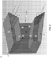
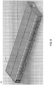
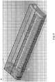
- illustrative air treatment apparatus 10 may generally include housing 12, which may generally define nozzle passage 14 extending through at least a portion of housing 12.
- Nozzle passage 14 may be defined by at least one wall (e.g., wall 16) of housing 12.
- housing 12 may generally define nozzle passage 14 having a generally quadrilateral cross-section (e.g., a rectangular cross-section in the illustrated embodiment).
- housing 12 may generally include four walls (e.g., walls 16, 18, 20, 22) defining generally rectangular cross-section nozzle passage 14.
- the nozzle passage may include other cross-sections (e.g., round, oval, and/or other polygonal or semi-polygonal cross-sections).
- the number of walls defining the nozzle passage may vary.
- the nozzle passage may be defined by a single wall.
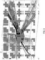
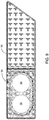
- the at least one wall defining nozzle passage 14 may include a vent (e.g. vents 24, 26 respectively associated with walls 16, 18, as shown in FIG. 2 ) adjacent to an upstream portion of the walls 16, 18.
- a blower may create an airflow that may be directed through vents 24, 26 and along at least a portion of walls 16, 18.
- nozzle passage 14 may include a Coanda surface (e.g., Coanda surfaces 28, 30) adjacent to respective vents 24, 26.
- one or more of Coanda surfaces 28, 30 may form at least a portion of a downstream portion of vents 24, 26.
- a downstream portion of walls 16, 18 defining vents 24, 26 may include Coanda surfaces 28, 30.
- the combination of a Coanda surface adjacent to a vent included in a housing wall defining the nozzle passage may generally be referred to as a Coanda exhaust.
- a Coanda surface may generally include a surface having an at least partial airfoil shape which may give rise Coanda effect flow of the air exiting the vent, whereby the air may tend to be attracted to or "stick" to the Coanda surface and/or the walls defining the nozzle passage downstream from the vents.
- Coanda surfaces 28, 30 may allow vents 24, 26 to be generally flush with and/or be generally formed as slits in respective walls 16, 18 of the illustrated embodiment, as the airflow exiting vents 24, 26 may tend to follow Coanda surfaces 28, 30 allowing the airflow to be directed in a downstream direction along walls 16, 18.
- the vents may have a configuration other than a Coanda exhaust.
- an upstream (relative to a direction of airflow through the nozzle passage) portion of the wall defining the vent may protrude above the downstream wall portion, such that a vent opening may extend above the downstream wall portion, and may generally direct air exiting the vent along the downstream portion of the wall.
- Other configurations may similarly be utilized by which the vent may direct air exiting from the vent along the wall.
- one or more discrete vents or nozzles may be provided which may protrude at least partially into the nozzle passage. Such protruding vents or nozzles may generally direct an airflow exiting the vent or nozzles in a downstream direction through the nozzle passage.
- vents 24, 26 as being continuous openings generally extending along the upstream width of respective walls 16, 18, it will be appreciated that other configurations may be equally utilized.
- one or more of the vents may extend less than the entire width of a wall.
- each wall defining the nozzle passage may be provided with one or more discreet vents.
- Various additional / alternative configurations may be equally utilized.
- housing 12 of air treatment apparatus 10 may include two opposed walls (e.g., walls 16, 18) defining at least a portion of nozzle passage 14.
- each of generally opposed walls 16, 18 may include respective vents 24, 26 adjacent an upstream portion of each wall 16, 18 (and thereby, adjacent an upstream portion of nozzle passage 14).
- each of vents 24, 26 may be configured as a Coanda exhaust, being provide with respective Coanda surfaces 28, 30 adjacent to a downstream portion of vents 24, 26.
- a greater or fewer number of walls defining the nozzle passage may be provided with vents.
- the nozzle passage may have a generally rectangular cross-section
- each of the four walls defining the nozzle passage may include vents.
- only a single wall defining the nozzle passage may include a vent.
- the combination of the nozzle passage defined by the air treatment apparatus housing and the vents directing an airflow (e.g., which may include an exhaust flow from the blower) in a downstream direction relative to the nozzle passage may create an area of low pressure in a downstream portion of the nozzle passage and/or at a downstream location relative to the housing of the air treatment apparatus.
- the downstream area of low pressure may cause additional air upstream of the air treatment apparatus to be drawn into the nozzle passage, and to be discharged through the downstream end of the nozzle passage.
- the air treatment apparatus may be capable of creating a greater airflow through the nozzle passage than the airflow that is provided by the blower. That is, the airflow through the air treatment apparatus may be greater than the airflow through the blower.
- such a design may create higher exit airflow (cfm) and may thus better distribute the "cleaned" air that is exiting the air treatment apparatus.
- the configuration of the nozzle passage may, at least in part, facilitate the creation of the downstream area of low pressure, and thereby the entrainment of air via an upstream intake of the nozzle passage.
- a first portion of the at least one wall defining the nozzle passage may diverge outwardly relative to an axis of the nozzle passage at least at a location that is downstream from the vent.
- walls 16, 18 may be angled relative to an axis of nozzle passage 14, such that walls 16, 18 diverge relative to one another and relative to the axis of nozzle passage 14.
- the divergent arrangement of walls 16, 18 may facilitate the creation of an area of low pressure downstream from vents 24, 26.
- a second portion of the at least one wall may diverge outwardly away from the first portion of the wall relative to the axis of the nozzle passage downstream from the first portion of the wall.
- nozzle passage 14 may be further defined, at least in part, by housing wall portions 32, 34.
- Wall portions 32, 34 may, in some embodiments, include a downstream extension of respective walls 16, 18.
- wall portions 32, 34 may be oriented at an outwardly divergent angle relative to walls 16, 18. That is, the angle formed by wall portions 32, 34 relative to the axis of nozzle passage 14 may be greater than the angle formed by walls 16, 18 relative to the axis of nozzle passage 14.
- the further divergent orientation of wall portions 32, 34 may, in some embodiments, further facilitate the creation of an area of low pressure at a downstream location relative to vents 24, 26, and thereby increase the entrainment of air from outside the upstream intake of nozzle passage 14.
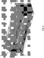
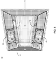
- housing 12 may define a housing interior (e.g., housing interiors 36, 38), which may at least partially surround nozzle passage 14.
- a photocatalytic reaction chamber e.g., photocatalytic reaction chambers 40, 42, which may be associated with respective vents 24, 26
- a blower e.g., blower 44
- housing interiors 36, 38 may be at least partially disposed within one or more of housing interiors 36, 38. While the illustrated embodiment depicts two photocatalytic reaction chamber (e.g., photocatalytic reaction chambers 40, 42), various embodiments may utilized one, or more than one photocatalytic reaction chambers.
- air treatment apparatus 10 is shown including a single blower (e.g., blower 44), in various embodiments one, or more than one, blowers may be utilized for providing an airflow through the one or more photocatalytic reaction chambers and out through the one or more vents.
- blower 44 e.g., blower 44
- one, or more than one, blowers may be utilized for providing an airflow through the one or more photocatalytic reaction chambers and out through the one or more vents.
- blower 44 may be fluidly coupled to convey air through the photocatalytic reaction chamber and to direct the air through the vent and along at least a portion of the at least one wall.
- housing 12 may further define a passage (e.g., passages 46, 48) fluidly coupling the blower, the photocatalytic reaction chamber, and the vent.
- a passage e.g., passages 46, 48
- an airflow generated by blower 44 may cause air to be directed through photocatalytic reaction chambers 40, 42, and to be directed out of vents 24, 26 via passages 46, 48. While only a single blower is depicted in FIG.
- blower 44 may include any suitable fan or blower for conveying air, including, but not limited to, an axial fan, a radial blower, a centrifugal air pump, an impeller, etc.
- the air treatment apparatus may include a photocatalytic reaction chamber (e.g., photocatalytic reaction chambers 40, 42 in the illustrative embodiment), which may include a plurality of photocatalytic media and a light source disposed to illuminate at least a portion of the photocatalytic media for producing a photocatalytic reaction generating a plurality of hydroxyl radicals.
- Photocatalytic reaction chambers 40, 42 may facilitate photocatalytic oxidation air treatment for killing and/or mineralizing bacteria, mold, fungi, spores, mycotoxins, viruses, allergens, other similar organic microorganisms or agents, and for oxidizing volatile organic compounds (VOC's).
- VOC's volatile organic compounds
- the photocatalytic reaction chambers may include the photocatalytic media and a light source. When illuminated by the light source, at least a portion of the photocatalytic media may produce a photocatalytic reaction that may generate a plurality of hydroxyl radicals.
- the hydroxyl radicals (OH-) produced by the photocatalytic reaction may be generally substantially surface bound (i.e. may exist along the surfaces of the photocatalytic media) and thus may generally not exit the photocatalytic reaction chamber. In some embodiments, the hydroxyl radicals produced by the photocatalytic reaction may be nearly 100% surface bound on the photocatalytic media.
- the photocatalytic oxidation may be substantially safe, e.g., for use around and/or in connection with perishable products, fixtures, as well as humans. This may be contrasted, for example, with systems using ozone, which may create a "free" floating hydroxyl radical (OH-) that may attack anything organic in the room being treated (e.g., also including human immune systems).
- the photocatalytic oxidation provided by an air treatment system herein may be capable of killing, mineralizing, and/or oxidizing small particles such as viruses and VOC's, which may be of a size that even HEPA filters may not be capable of removing.
- the photocatalytic reaction chamber of the present disclosure may be self cleaning.
- the reaction by products of killing and/or mineralizing bacteria, mold, fungi, spores, mycotoxins, viruses, allergens, other similar organic microorganisms or agents, and of oxidizing volatile organic compounds (VOC's) may generally include carbon dioxide and/or water vapor.
- Such reaction byproducts may be released through the media.
- the reaction byproducts may generally not build up on the photocatalytic media. Accordingly, in some embodiments, need or frequency of replacing the photocatalytic media may be reduced and/or eliminated.
- the photocatalytic media may include a media substrate coated with a micro-porous nano-particle membrane including a photocatalytic substance.
- This media substrate is non-reactive with the photocatalytic substance and thus induces the photocatalytic substance to form on each media substrate as a nano-particle structure rather than as a merely closed packed layer
- the media substrate may include, glass-type materials, bora silica glass, ceramic materials, metallic materials, plastics, etc.
- materials that may normally be reactive with a photocatalytic substance applied thereto may be pre-coated with another substance that renders them non-reactive with the photocatalytic substance prior to coating them with the photocatalytic substance.
- the media substrate may be provided having various shapes and configurations, e.g., which may provide relatively high surface area while permitting adequate airflow through the photocatalytic reaction chamber.
- the media substrate may be provided having cylindrical, spherical, tubular, toroidal, polyhedrical, or other suitable shapes.
- the photocatalytic substance may include TiO 2 and the light source may emit ultraviolet light having a wavelength less than about 400 nm.
- the photocatalytic substance may include at least one of ZnO and a WO3, and the light source may emit light in the visible spectrum. Any suitable light sources emitting light in the activating wavelengths may be utilized in connection with the present disclosure, including, but not limited to, fluorescent light sources, incandescent light sources, LED light sources, etc.
- photocatalytic substances may be utilized, which may, when illuminated with light of an appropriate wavelength, generate hydroxyl radicals that may be capable of killing and/or mineralizing bacteria, mold, fungi, spores, mycotoxins, viruses, allergens, other similar organic microorganisms or agents, and for oxidizing volatile organic compounds (VOC's).
- VOC's volatile organic compounds
- the photocatalytic media may include a single photocatalytic substance (e.g., TiO2, ZnO, WO3), and/or may include combinations of photocatalytic substances. Further, in some embodiments, the photocatalytic media may include one or more enhancing substances. An enhancing substance may, for example, increase the reaction rate of the photocatalytic reaction, which may increase the number of hydroxyl radicals that may be generated and/or available for an oxidation reaction.
- An enhancing substance may, for example, increase the reaction rate of the photocatalytic reaction, which may increase the number of hydroxyl radicals that may be generated and/or available for an oxidation reaction.
- the media substrate may be coated with a micro-porous nano-particle membrane including the photocatalytic substance.
- the photocatalytic substance may be coated on the media substrate to provide a micro-porous nano-particle membrane according to any suitable techniques, example of which techniques may be disclosed in US Patent No. 5,006,248, issued 9 April 1991, to Anderson, et al. ; US Patent No. 5,035,784, issued 30 July 1991, to Anderson, et al. ; and US Patent No. 5,227,342, issued 13 July 1993, to Anderson, et al. , the entire disclosure of all of which are incorporated herein by reference.
- providing the photocatalytic substance as a micro-porous nano-particle membrane on the media substrate may dramatically increases the number of reaction sites available for bacteria, mold, fungi, spores, mycotoxins, viruses, allergens, other similar organic microorganisms and/or agents, and VOC's to be killed, mineralized, and/or oxidized by the hydroxyl radicals (OH-) produced as part of the photocatalytic reaction, when the media substrate coated with the photocatalytic substance is exposed to an activating light (for example, ultraviolet light, e.g., generally having a wavelength less than about 400 nm, in the case of a media coated with Ti0 2 .
- an activating light for example, ultraviolet light, e.g., generally having a wavelength less than about 400 nm, in the case of a media coated with Ti0 2 .
- providing the photocatalytic substance as a micro-porous nano-particle membrane on the media substrates may, in some embodiments, create a relatively durable and/or permanent bond between the photocatalytic substance and the media substrate.
- the bond between the photocatalytic substance and the media substrate may be achieved, at least in part, as a result of a dopant used in connection with the production of the photocatalytic substance (e.g., which may, in some embodiments, include a technique described in one or more of the above-referenced US Patents), which may prevent and/or reduce the photocatalytic substance (e.g., Ti0 2 , ZnO, W0 3 , etc.) from migrating and clumping up (e.g. during the coating process).
- the photocatalytic substance may typically not delaminate from the media substrates. This may, in some instances, provide a significant advantage over other Ti0 2 coated filters and/or devices using photocatalytic oxidation technology, e.g., which may experience delamination and may need to be replaced.
- the photocatalytic reaction chamber may include a removable reaction chamber cartridge.
- at least a portion of the plurality of photocatalytic media and the light source may be at least partially contained within the reaction chamber cartridge.
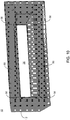
- photocatalytic reaction chamber 40 may include removable reaction chamber cartridge 50.
- Light source 52 may be at least partially disposed within removable reaction chamber cartridge 50. While light source 52 is illustrated as a fluorescent-tube type light source, such depiction is intended only for the purpose of illustration as other suitable light source configurations may suitably utilized.
- Removable reaction chamber cartridge 50 may additionally provide one or more connection features 54, e.g., which may provide electrical and/or mechanical connection between removable reaction chamber cartridge (e.g., including light source 52) and one or more power supplies and/or control circuits associated with air treatment apparatus 10. As shown in FIG. 9 , at least a portion of light source 52 may be at least partially surrounded by at least a portion of the plurality of photocatalytic media 56.
- removable reaction chamber cartridge 50 may be configured to be releasable coupled with housing 12. For example, at least a portion of removable reaction chamber cartridge 50 may be received within housing interiors 36, 38 of housing 12. Further, removable reaction chamber cartridge 50 may be releasably coupled with housing 12, e.g., via one or more spring latches 58, or other suitable retentions features (e.g., snap-fits, screws, clips, etc.). In an embodiment, the releasable coupling of removable reaction chamber cartridge 50 with housing 12 may facilitate user removal and/or replacement of removable reaction chamber cartridge 50.
- Removable reaction chamber cartridge 50 may allow facile replacement of both the photocatalytic media and the light source, which may both be contained within removable reaction chamber cartridge 50.
- air treatment apparatus 10 may include one or more control systems (e.g., control system 60).
- Control system 60 may be coupled for controlling the operation of one or more of blower 44 and removable reaction chamber cartridge 50 (e.g., light source 52 included within removable reaction chamber cartridge 50), and/or provide other control functionality.
- the replacement cycle e.g., the time between cartridge replacement
- removable reaction chamber cartridge 50 may have a one year replacement cycle, a two year replacement cycle, a five year replacement cycle, or other suitable replacement cycle.
- control system 60 may monitor a usage sensor/timer (e.g., which may include a sensor associated with removable reaction chamber cartridge 50 and/or a usage timer that may be associated with control system 60 and/or removable reaction chamber cartridge 50). Upon the detection of 11 months of operation (and/or another suitable interval), control system 60 may activate an indicator light alerting the user that it is time to order a replacement removable reaction chamber cartridge (i.e. which may include the light source and the photocatalytic media). Upon replacement of removable reaction chamber cartridge, the usage timer may begin to measure usage of the new removable reaction chamber cartridge, and may accumulate time when the air treatment apparatus is operating.
- a usage sensor/timer e.g., which may include a sensor associated with removable reaction chamber cartridge 50 and/or a usage timer that may be associated with control system 60 and/or removable reaction chamber cartridge 50.
- blower 44 may be capable of operating at multiple speeds (e.g., a high speed and a low speed), which may provide relative airflow.
- the speed of blower 44 may be controlled via control system 60.
- control system 60 may allow a user of air treatment apparatus 10 to manually select between the different blower speeds.
- control system 60 may provide an automatic blower speed control.
- control system 60 may operate blower 44 at a first blower speed (for example, at a high blower speed) until a desired pre-set condition in the room (for example, an ambient light level, a temperature in the room, etc.).
- control system 60 may automatically switch to operating blower 44 at a second blower speed (e.g., a low blower speed).
- a second blower speed e.g., a low blower speed
- the automatic blower speed control provided by control system 60 may allow air treatment apparatus 10 to operate at a relatively quiet noise level (e.g., as may be provided by a lower blower speed) at night time.
- control system 60 may similarly control an illumination level of any indicator lights/LED's and/or user interface illumination levels. For example, upon detecting an ambient light level below a pre-set threshold control system 60 may reduce the illumination level of any indicator lights/LED's and/or user interface illumination levels to a predetermined "night time" illumination level. The reduction in the illumination level may, for example, thereby reduce the light pollution generated at night. Correspondingly, in response to detecting an ambient light level above a pre-set threshold, control system 60 may increase the illumination level of any indicator lights/LED's and/or user interface illumination levels to a predetermined "day time" illumination level.
- control system 60 may further provide one or more safety features.
- control system 60 may be configured to provide an over-temperature shut-off.
- air treatment apparatus 10 may include an over-heat sensor (e.g., a thermal switch, which may be associated with one or more of blower 44, light source 52 / removable reaction chamber cartridge 50, and/or control system 60).
- a temperature above a preset threshold temperature may be indicative of, for example, a malfunction or failure of blower 44 and/or light source 52.
- a temperature above a preset threshold temperature e.g.
- the over-heat sensor and/or control system 60 may power-down air treatment apparatus 10 (e.g., and/or blower 44 and light source 52).
- control system 60 may active a warning indicator light in response to detecting the over-temperature condition.
- air treatment apparatus 10 may remain powered-down until the detected temperature falls below a preset safe operation temperature, and/or until manually reset by a user.
- air treatment apparatus 10 may provide facile access to removable reaction chamber cartridge 50.
- grill 62 may removably attach to housing 12, e.g., via snap-fits, spring clips, or other suitable removable attachment mechanism.
- Removable reaction chamber cartridge(s) 50 and latches may be accessible with grill 62 removed from housing 12.
- grill 62 may also protect, decoratively cover, and/or provide filtering of air intake (as indicated by arrows in FIG. 2 ) into housing interior 36, 38, which may be fluidly coupled with an air intake of blower 44 and/or photocatalytic reaction chambers 40, 42 / removable reaction chamber cartridge 50.
- air treatment apparatus 10 may be provided having a relatively compact design.
- the relatively compact design may, for example, allow for easy installation of air treatment apparatus 10. Further, the relatively compact design may also make air treatment apparatus 10 relatively easy to move from one location to another.
- Air treatment apparatus may, suitably be used in a variety of locations including, but not limited to, bedrooms, bathrooms, kitchens, living rooms, studies, dining rooms, family rooms, etc.
- air treatment apparatus 10 may suitably be located on top of a desk, dresser, cabinet, table, storage bin, etc. Further, air treatment apparatus 10 may be used in conjunction with a stand, or it can be mounted to a wall and/or ceiling.
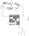
- air treatment apparatus may suitably be placed and/or mounted in a horizontal configuration (as shown in FIG. 13 ) and/or a vertical configuration (as shown in FIG. 14 ).
Landscapes
- Engineering & Computer Science (AREA)
- Health & Medical Sciences (AREA)
- General Engineering & Computer Science (AREA)
- Mechanical Engineering (AREA)
- General Health & Medical Sciences (AREA)
- Epidemiology (AREA)
- Veterinary Medicine (AREA)
- Public Health (AREA)
- Animal Behavior & Ethology (AREA)
- Life Sciences & Earth Sciences (AREA)
- Chemical & Material Sciences (AREA)
- Physics & Mathematics (AREA)
- Fluid Mechanics (AREA)
- Combustion & Propulsion (AREA)
- Chemical Kinetics & Catalysis (AREA)
- Disinfection, Sterilisation Or Deodorisation Of Air (AREA)
- Catalysts (AREA)
- Physical Or Chemical Processes And Apparatus (AREA)
Applications Claiming Priority (2)
| Application Number | Priority Date | Filing Date | Title |
|---|---|---|---|
| US201261594575P | 2012-02-03 | 2012-02-03 | |
| PCT/US2013/024319 WO2013116630A2 (en) | 2012-02-03 | 2013-02-01 | Air treatment system |
Publications (3)
| Publication Number | Publication Date |
|---|---|
| EP2809359A2 EP2809359A2 (en) | 2014-12-10 |
| EP2809359A4 EP2809359A4 (en) | 2016-07-13 |
| EP2809359B1 true EP2809359B1 (en) | 2018-10-24 |
Family
ID=48903055
Family Applications (1)
| Application Number | Title | Priority Date | Filing Date |
|---|---|---|---|
| EP13743821.4A Not-in-force EP2809359B1 (en) | 2012-02-03 | 2013-02-01 | Photocatalytic air treatment system |
Country Status (10)
| Country | Link |
|---|---|
| US (1) | US8961895B2 (zh) |
| EP (1) | EP2809359B1 (zh) |
| JP (1) | JP6165177B2 (zh) |
| KR (1) | KR102166570B1 (zh) |
| CN (1) | CN104703631B (zh) |
| AU (1) | AU2013214971A1 (zh) |
| CA (1) | CA2863652C (zh) |
| HK (1) | HK1205003A1 (zh) |
| TW (2) | TWI623713B (zh) |
| WO (1) | WO2013116630A2 (zh) |
Families Citing this family (11)
| Publication number | Priority date | Publication date | Assignee | Title |
|---|---|---|---|---|
| CA2917679C (en) | 2015-01-16 | 2019-09-10 | Air System Components, Inc. | Lighting control for chilled beam |
| US20160209075A1 (en) | 2015-01-16 | 2016-07-21 | Air System Components, Inc. | Duct interface for chilled beam |
| WO2016168676A1 (en) * | 2015-04-17 | 2016-10-20 | Air System Components, Inc. | Control of a lighting with chilled beam |
| US10780192B2 (en) * | 2015-09-16 | 2020-09-22 | The Procter & Gamble Company | Microfluidic delivery cartridges and methods of connecting cartridges with microfluidic delivery systems |
| ITUA20161748A1 (it) | 2016-03-17 | 2017-09-17 | I M A Industria Macch Automatiche S P A In Sigla Ima S P A | Gruppo per la regolarizzazione e laminazione di un flusso gassoso |
| KR20210039201A (ko) | 2019-10-01 | 2021-04-09 | 삼성전자주식회사 | 재생 가능한 세라믹 촉매필터와 이를 포함하는 필터링 시스템 및 그 관리방법 |
| EP3847894A1 (en) | 2020-01-13 | 2021-07-14 | Mundus Aer Oy | System for a storage / transport space for removing ethylene present in the air from a closed space, and corresponding method |
| KR20210105722A (ko) | 2020-02-19 | 2021-08-27 | 삼성전자주식회사 | 오염 물질 정화제, 이를 포함한 오염 물질 정화 필터 및 이를 포함한 오염 물질 정화 장치 |
| IT202000003710A1 (it) * | 2020-02-21 | 2021-08-21 | Ernestomeda S P A | Dispositivo di trattamento dell’aria |
| KR20220126157A (ko) | 2021-03-08 | 2022-09-15 | 삼성전자주식회사 | 복합 광촉매 구조체, 이를 포함하는 광촉매 필터 및 공기정화장치 |
| US20220412590A1 (en) * | 2021-06-28 | 2022-12-29 | Haier Us Appliance Solutions, Inc. | Air conditioning unit with fan performance monitoring by a temperature sensor |
Family Cites Families (35)
| Publication number | Priority date | Publication date | Assignee | Title |
|---|---|---|---|---|
| US5035784A (en) | 1987-07-27 | 1991-07-30 | Wisconsin Alumni Research Foundation | Degradation of organic chemicals with titanium ceramic membranes |
| US5006248A (en) | 1989-10-23 | 1991-04-09 | Wisconsin Alumni Research Foundation | Metal oxide porous ceramic membranes with small pore sizes |
| JPH0746265Y2 (ja) * | 1991-03-15 | 1995-10-25 | 株式会社玉初堂 | 薫香用香炉カバー |
| US5227342A (en) | 1991-05-01 | 1993-07-13 | Wisconsin Alumni Research Foundation | Process of making porous ceramic materials with controlled porosity |
| US6544485B1 (en) * | 2001-01-29 | 2003-04-08 | Sharper Image Corporation | Electro-kinetic device with enhanced anti-microorganism capability |
| JP3440896B2 (ja) * | 1999-09-14 | 2003-08-25 | ダイキン工業株式会社 | 空気清浄装置 |
| JP3438684B2 (ja) * | 1999-11-05 | 2003-08-18 | ダイキン工業株式会社 | 天井埋込型空気調和装置 |
| JP2001149452A (ja) * | 1999-11-30 | 2001-06-05 | Daido Steel Co Ltd | ガス浄化装置におけるフィルタユニット |
| US6855295B2 (en) * | 2000-07-17 | 2005-02-15 | John C. Kulp | UV air cleaning and disinfecting system |
| FI113798B (fi) * | 2000-11-24 | 2004-06-15 | Halton Oy | Tuloilmalaite |
| JP2003322370A (ja) * | 2002-05-02 | 2003-11-14 | Tonichi Service Kk | 光触媒空気清浄装置 |
| JP3971991B2 (ja) * | 2002-12-03 | 2007-09-05 | 株式会社日立産機システム | エアシャワ装置 |
| EP1520615A1 (fr) * | 2003-10-01 | 2005-04-06 | R & D du groupe Cockerill-Sambre | Paroi de purification d'air |
| US20050112039A1 (en) * | 2003-11-26 | 2005-05-26 | Sheehan Darren S. | Ultraviolet purification system |
| TWM273695U (en) * | 2005-01-21 | 2005-08-21 | Ever Cleaning Air Co Ltd | Improved structure of a ceiling embedded type sterilizing air cleaner |
| JP3110098U (ja) * | 2005-01-28 | 2005-06-16 | 株式会社細山田商事 | 消臭機能付き室内空気循環装置 |
| US8002881B2 (en) * | 2005-03-16 | 2011-08-23 | Oy Halton Group Ltd. | Fume treatment method and apparatus using ultraviolet light to degrade contaminants |
| TWM283970U (en) * | 2005-07-07 | 2005-12-21 | Hung-Shing Wang | Concealed and suspended indoor unit of air conditioner having nano-scaled photo catalyst air purification function module |
| JP2009514654A (ja) * | 2005-11-08 | 2009-04-09 | ネクスト セイフティ インク | 空気供給装置 |
| US20070101867A1 (en) * | 2005-11-08 | 2007-05-10 | Hunter Charles E | Air sterilization apparatus |
| US20070102280A1 (en) * | 2005-11-08 | 2007-05-10 | Hunter C E | Air supply apparatus |
| US20090280027A1 (en) * | 2006-03-27 | 2009-11-12 | Hayman Jr John J | Photocatalytic air treatment system and method |
| JP2008079907A (ja) * | 2006-09-28 | 2008-04-10 | Lion Corp | 消臭装置 |
| WO2008058290A2 (en) | 2006-11-09 | 2008-05-15 | Kronos Advanced Technologies, Inc. | Method of and apparatus for cleaning and disinfection of air |
| JP5333714B2 (ja) * | 2008-03-14 | 2013-11-06 | 株式会社トルネックス | 天井埋込型空気清浄機 |
| JP5775248B2 (ja) * | 2008-03-21 | 2015-09-09 | 国立大学法人 東京大学 | 光触媒材料、有機物分解方法、内装部材、空気清浄装置、酸化剤製造装置 |
| GB2466058B (en) * | 2008-12-11 | 2010-12-22 | Dyson Technology Ltd | Fan nozzle with spacers |
| DE102008062178A1 (de) * | 2008-12-13 | 2010-06-17 | Schaeffler Kg | Schaltbarer Tassenstößel |
| US8404273B2 (en) * | 2009-04-24 | 2013-03-26 | Old Dominion University Research Foundation | Wound care system and bactericidal methods and devices |
| US20110033346A1 (en) * | 2009-08-04 | 2011-02-10 | Bohlen Johns R | Air cleaner with photo-catalytic oxidizer |
| KR101643223B1 (ko) * | 2009-10-14 | 2016-07-27 | 엘지전자 주식회사 | 공기조화장치 및 그 제어방법 |
| EP2491956A4 (en) * | 2009-10-19 | 2013-11-20 | Univ Tokyo | METHOD FOR INACTIVATION OF A VIRUS AND ARTICLE PROVIDED WITH ANTIVIRAL PROPERTIES |
| FI122965B (fi) * | 2009-12-09 | 2012-09-14 | Halton Oy | Tuloilmalaite ja menetelmä ilmanvaihdossa |
| US20110236284A1 (en) * | 2010-03-25 | 2011-09-29 | Toto Ltd. | Photocatalyst-coated body and photocatalytic coating liquid |
| US9393338B2 (en) * | 2010-11-18 | 2016-07-19 | Oy Halton Group Ltd. | Air purification devices methods and systems |
-
2013
- 2013-02-01 AU AU2013214971A patent/AU2013214971A1/en not_active Abandoned
- 2013-02-01 WO PCT/US2013/024319 patent/WO2013116630A2/en active Application Filing
- 2013-02-01 EP EP13743821.4A patent/EP2809359B1/en not_active Not-in-force
- 2013-02-01 KR KR1020147024189A patent/KR102166570B1/ko active IP Right Grant
- 2013-02-01 US US13/756,810 patent/US8961895B2/en not_active Expired - Fee Related
- 2013-02-01 CA CA2863652A patent/CA2863652C/en not_active Expired - Fee Related
- 2013-02-01 JP JP2014555743A patent/JP6165177B2/ja active Active
- 2013-02-01 CN CN201380008043.8A patent/CN104703631B/zh not_active Expired - Fee Related
- 2013-02-04 TW TW102104299A patent/TWI623713B/zh not_active IP Right Cessation
- 2013-02-04 TW TW107103554A patent/TWI660146B/zh not_active IP Right Cessation
-
2015
- 2015-06-09 HK HK15105460.3A patent/HK1205003A1/zh not_active IP Right Cessation
Also Published As
| Publication number | Publication date |
|---|---|
| WO2013116630A3 (en) | 2015-03-12 |
| AU2013214971A8 (en) | 2014-10-09 |
| TW201344119A (zh) | 2013-11-01 |
| EP2809359A2 (en) | 2014-12-10 |
| HK1205003A1 (zh) | 2015-12-11 |
| KR20150056498A (ko) | 2015-05-26 |
| JP6165177B2 (ja) | 2017-07-19 |
| EP2809359A4 (en) | 2016-07-13 |
| KR102166570B1 (ko) | 2020-10-16 |
| TW201814219A (zh) | 2018-04-16 |
| JP2015518380A (ja) | 2015-07-02 |
| CN104703631B (zh) | 2018-06-01 |
| US8961895B2 (en) | 2015-02-24 |
| CN104703631A (zh) | 2015-06-10 |
| WO2013116630A2 (en) | 2013-08-08 |
| CA2863652C (en) | 2019-03-19 |
| US20130202494A1 (en) | 2013-08-08 |
| AU2013214971A1 (en) | 2014-08-28 |
| TWI623713B (zh) | 2018-05-11 |
| CA2863652A1 (en) | 2013-08-08 |
| TWI660146B (zh) | 2019-05-21 |
Similar Documents
| Publication | Publication Date | Title |
|---|---|---|
| EP2809359B1 (en) | Photocatalytic air treatment system | |
| US11859624B2 (en) | Ceiling tile with built-in air flow mechanism | |
| US11060712B2 (en) | Combination LED lighting and fan apparatus | |
| US20170080373A1 (en) | Air purification system | |
| US20040166037A1 (en) | Air filtration and treatment apparatus | |
| EP1556093A2 (en) | Cleaning of air | |
| GB2515842A (en) | Apparatus for purifying air | |
| WO2021229204A2 (en) | Air filtration system | |
| KR20170039019A (ko) | 침대용 공기 정화기 및 광촉매-공기조화 모듈 | |
| CN205090506U (zh) | 空气处理装置 | |
| US20230181788A1 (en) | An air sanitizer | |
| US11998667B2 (en) | Air purification device | |
| JP2021521914A (ja) | 空気浄化モジュール及びこれを含む冷蔵庫 | |
| KR102527622B1 (ko) | 무덕트형 고풍속 공기살균기 | |
| KR102640593B1 (ko) | 무드등이 구비된 수면용 공기청정기 | |
| US20220118149A1 (en) | Germicidal Lighting Fixture Using Photocatalytic Oxidation | |
| JP2024513060A (ja) | Uvc浄化モジュール及び相対モジュール浄化集合体 | |
| KR20210043431A (ko) | 조명기구일체형 공기정화시스템 | |
| KR20230094901A (ko) | 방역형 공기살균정화기 |
Legal Events
| Date | Code | Title | Description |
|---|---|---|---|
| PUAI | Public reference made under article 153(3) epc to a published international application that has entered the european phase |
Free format text: ORIGINAL CODE: 0009012 |
|
| 17P | Request for examination filed |
Effective date: 20140903 |
|
| AK | Designated contracting states |
Kind code of ref document: A2 Designated state(s): AL AT BE BG CH CY CZ DE DK EE ES FI FR GB GR HR HU IE IS IT LI LT LU LV MC MK MT NL NO PL PT RO RS SE SI SK SM TR |
|
| AX | Request for extension of the european patent |
Extension state: BA ME |
|
| R17D | Deferred search report published (corrected) |
Effective date: 20150312 |
|
| RAP1 | Party data changed (applicant data changed or rights of an application transferred) |
Owner name: AKIDA HOLDINGS, LLC |
|
| REG | Reference to a national code |
Ref country code: HK Ref legal event code: DE Ref document number: 1205003 Country of ref document: HK |
|
| DAX | Request for extension of the european patent (deleted) | ||
| RIC1 | Information provided on ipc code assigned before grant |
Ipc: F24F 3/16 20060101ALI20160215BHEP Ipc: A61L 9/20 20060101AFI20160215BHEP |
|
| REG | Reference to a national code |
Ref country code: DE Ref legal event code: R079 Ref document number: 602013045563 Country of ref document: DE Free format text: PREVIOUS MAIN CLASS: A61L0009000000 Ipc: A61L0009200000 |
|
| A4 | Supplementary search report drawn up and despatched |
Effective date: 20160610 |
|
| RIC1 | Information provided on ipc code assigned before grant |
Ipc: A61L 9/20 20060101AFI20160606BHEP Ipc: A61L 2/10 20060101ALI20160606BHEP Ipc: F24F 3/16 20060101ALI20160606BHEP Ipc: A61L 2/08 20060101ALI20160606BHEP |
|
| GRAP | Despatch of communication of intention to grant a patent |
Free format text: ORIGINAL CODE: EPIDOSNIGR1 |
|
| STAA | Information on the status of an ep patent application or granted ep patent |
Free format text: STATUS: GRANT OF PATENT IS INTENDED |
|
| INTG | Intention to grant announced |
Effective date: 20170811 |
|
| GRAS | Grant fee paid |
Free format text: ORIGINAL CODE: EPIDOSNIGR3 |
|
| GRAJ | Information related to disapproval of communication of intention to grant by the applicant or resumption of examination proceedings by the epo deleted |
Free format text: ORIGINAL CODE: EPIDOSDIGR1 |
|
| GRAL | Information related to payment of fee for publishing/printing deleted |
Free format text: ORIGINAL CODE: EPIDOSDIGR3 |
|
| STAA | Information on the status of an ep patent application or granted ep patent |
Free format text: STATUS: REQUEST FOR EXAMINATION WAS MADE |
|
| INTC | Intention to grant announced (deleted) | ||
| STAA | Information on the status of an ep patent application or granted ep patent |
Free format text: STATUS: EXAMINATION IS IN PROGRESS |
|
| 17Q | First examination report despatched |
Effective date: 20180131 |
|
| GRAP | Despatch of communication of intention to grant a patent |
Free format text: ORIGINAL CODE: EPIDOSNIGR1 |
|
| STAA | Information on the status of an ep patent application or granted ep patent |
Free format text: STATUS: GRANT OF PATENT IS INTENDED |
|
| INTG | Intention to grant announced |
Effective date: 20180508 |
|
| GRAA | (expected) grant |
Free format text: ORIGINAL CODE: 0009210 |
|
| STAA | Information on the status of an ep patent application or granted ep patent |
Free format text: STATUS: THE PATENT HAS BEEN GRANTED |
|
| AK | Designated contracting states |
Kind code of ref document: B1 Designated state(s): AL AT BE BG CH CY CZ DE DK EE ES FI FR GB GR HR HU IE IS IT LI LT LU LV MC MK MT NL NO PL PT RO RS SE SI SK SM TR |
|
| REG | Reference to a national code |
Ref country code: CH Ref legal event code: EP |
|
| REG | Reference to a national code |
Ref country code: IE Ref legal event code: FG4D |
|
| REG | Reference to a national code |
Ref country code: AT Ref legal event code: REF Ref document number: 1055910 Country of ref document: AT Kind code of ref document: T Effective date: 20181115 |
|
| REG | Reference to a national code |
Ref country code: DE Ref legal event code: R096 Ref document number: 602013045563 Country of ref document: DE |
|
| REG | Reference to a national code |
Ref country code: NL Ref legal event code: MP Effective date: 20181024 |
|
| REG | Reference to a national code |
Ref country code: LT Ref legal event code: MG4D |
|
| REG | Reference to a national code |
Ref country code: AT Ref legal event code: MK05 Ref document number: 1055910 Country of ref document: AT Kind code of ref document: T Effective date: 20181024 |
|
| PG25 | Lapsed in a contracting state [announced via postgrant information from national office to epo] |
Ref country code: NL Free format text: LAPSE BECAUSE OF FAILURE TO SUBMIT A TRANSLATION OF THE DESCRIPTION OR TO PAY THE FEE WITHIN THE PRESCRIBED TIME-LIMIT Effective date: 20181024 |
|
| PG25 | Lapsed in a contracting state [announced via postgrant information from national office to epo] |
Ref country code: NO Free format text: LAPSE BECAUSE OF FAILURE TO SUBMIT A TRANSLATION OF THE DESCRIPTION OR TO PAY THE FEE WITHIN THE PRESCRIBED TIME-LIMIT Effective date: 20190124 Ref country code: LT Free format text: LAPSE BECAUSE OF FAILURE TO SUBMIT A TRANSLATION OF THE DESCRIPTION OR TO PAY THE FEE WITHIN THE PRESCRIBED TIME-LIMIT Effective date: 20181024 Ref country code: IS Free format text: LAPSE BECAUSE OF FAILURE TO SUBMIT A TRANSLATION OF THE DESCRIPTION OR TO PAY THE FEE WITHIN THE PRESCRIBED TIME-LIMIT Effective date: 20190224 Ref country code: AT Free format text: LAPSE BECAUSE OF FAILURE TO SUBMIT A TRANSLATION OF THE DESCRIPTION OR TO PAY THE FEE WITHIN THE PRESCRIBED TIME-LIMIT Effective date: 20181024 Ref country code: LV Free format text: LAPSE BECAUSE OF FAILURE TO SUBMIT A TRANSLATION OF THE DESCRIPTION OR TO PAY THE FEE WITHIN THE PRESCRIBED TIME-LIMIT Effective date: 20181024 Ref country code: ES Free format text: LAPSE BECAUSE OF FAILURE TO SUBMIT A TRANSLATION OF THE DESCRIPTION OR TO PAY THE FEE WITHIN THE PRESCRIBED TIME-LIMIT Effective date: 20181024 Ref country code: BG Free format text: LAPSE BECAUSE OF FAILURE TO SUBMIT A TRANSLATION OF THE DESCRIPTION OR TO PAY THE FEE WITHIN THE PRESCRIBED TIME-LIMIT Effective date: 20190124 Ref country code: HR Free format text: LAPSE BECAUSE OF FAILURE TO SUBMIT A TRANSLATION OF THE DESCRIPTION OR TO PAY THE FEE WITHIN THE PRESCRIBED TIME-LIMIT Effective date: 20181024 Ref country code: PL Free format text: LAPSE BECAUSE OF FAILURE TO SUBMIT A TRANSLATION OF THE DESCRIPTION OR TO PAY THE FEE WITHIN THE PRESCRIBED TIME-LIMIT Effective date: 20181024 |
|
| PGFP | Annual fee paid to national office [announced via postgrant information from national office to epo] |
Ref country code: DE Payment date: 20190321 Year of fee payment: 7 Ref country code: FI Payment date: 20190228 Year of fee payment: 7 |
|
| PG25 | Lapsed in a contracting state [announced via postgrant information from national office to epo] |
Ref country code: SE Free format text: LAPSE BECAUSE OF FAILURE TO SUBMIT A TRANSLATION OF THE DESCRIPTION OR TO PAY THE FEE WITHIN THE PRESCRIBED TIME-LIMIT Effective date: 20181024 Ref country code: PT Free format text: LAPSE BECAUSE OF FAILURE TO SUBMIT A TRANSLATION OF THE DESCRIPTION OR TO PAY THE FEE WITHIN THE PRESCRIBED TIME-LIMIT Effective date: 20190224 Ref country code: AL Free format text: LAPSE BECAUSE OF FAILURE TO SUBMIT A TRANSLATION OF THE DESCRIPTION OR TO PAY THE FEE WITHIN THE PRESCRIBED TIME-LIMIT Effective date: 20181024 Ref country code: GR Free format text: LAPSE BECAUSE OF FAILURE TO SUBMIT A TRANSLATION OF THE DESCRIPTION OR TO PAY THE FEE WITHIN THE PRESCRIBED TIME-LIMIT Effective date: 20190125 Ref country code: RS Free format text: LAPSE BECAUSE OF FAILURE TO SUBMIT A TRANSLATION OF THE DESCRIPTION OR TO PAY THE FEE WITHIN THE PRESCRIBED TIME-LIMIT Effective date: 20181024 |
|
| PGFP | Annual fee paid to national office [announced via postgrant information from national office to epo] |
Ref country code: FR Payment date: 20190228 Year of fee payment: 7 |
|
| REG | Reference to a national code |
Ref country code: DE Ref legal event code: R097 Ref document number: 602013045563 Country of ref document: DE |
|
| PG25 | Lapsed in a contracting state [announced via postgrant information from national office to epo] |
Ref country code: CZ Free format text: LAPSE BECAUSE OF FAILURE TO SUBMIT A TRANSLATION OF THE DESCRIPTION OR TO PAY THE FEE WITHIN THE PRESCRIBED TIME-LIMIT Effective date: 20181024 Ref country code: DK Free format text: LAPSE BECAUSE OF FAILURE TO SUBMIT A TRANSLATION OF THE DESCRIPTION OR TO PAY THE FEE WITHIN THE PRESCRIBED TIME-LIMIT Effective date: 20181024 Ref country code: IT Free format text: LAPSE BECAUSE OF FAILURE TO SUBMIT A TRANSLATION OF THE DESCRIPTION OR TO PAY THE FEE WITHIN THE PRESCRIBED TIME-LIMIT Effective date: 20181024 |
|
| PG25 | Lapsed in a contracting state [announced via postgrant information from national office to epo] |
Ref country code: EE Free format text: LAPSE BECAUSE OF FAILURE TO SUBMIT A TRANSLATION OF THE DESCRIPTION OR TO PAY THE FEE WITHIN THE PRESCRIBED TIME-LIMIT Effective date: 20181024 Ref country code: SM Free format text: LAPSE BECAUSE OF FAILURE TO SUBMIT A TRANSLATION OF THE DESCRIPTION OR TO PAY THE FEE WITHIN THE PRESCRIBED TIME-LIMIT Effective date: 20181024 Ref country code: SK Free format text: LAPSE BECAUSE OF FAILURE TO SUBMIT A TRANSLATION OF THE DESCRIPTION OR TO PAY THE FEE WITHIN THE PRESCRIBED TIME-LIMIT Effective date: 20181024 Ref country code: RO Free format text: LAPSE BECAUSE OF FAILURE TO SUBMIT A TRANSLATION OF THE DESCRIPTION OR TO PAY THE FEE WITHIN THE PRESCRIBED TIME-LIMIT Effective date: 20181024 |
|
| PLBE | No opposition filed within time limit |
Free format text: ORIGINAL CODE: 0009261 |
|
| STAA | Information on the status of an ep patent application or granted ep patent |
Free format text: STATUS: NO OPPOSITION FILED WITHIN TIME LIMIT |
|
| REG | Reference to a national code |
Ref country code: CH Ref legal event code: PL |
|
| 26N | No opposition filed |
Effective date: 20190725 |
|
| PG25 | Lapsed in a contracting state [announced via postgrant information from national office to epo] |
Ref country code: MC Free format text: LAPSE BECAUSE OF FAILURE TO SUBMIT A TRANSLATION OF THE DESCRIPTION OR TO PAY THE FEE WITHIN THE PRESCRIBED TIME-LIMIT Effective date: 20181024 Ref country code: LU Free format text: LAPSE BECAUSE OF NON-PAYMENT OF DUE FEES Effective date: 20190201 Ref country code: SI Free format text: LAPSE BECAUSE OF FAILURE TO SUBMIT A TRANSLATION OF THE DESCRIPTION OR TO PAY THE FEE WITHIN THE PRESCRIBED TIME-LIMIT Effective date: 20181024 |
|
| PGFP | Annual fee paid to national office [announced via postgrant information from national office to epo] |
Ref country code: GB Payment date: 20190403 Year of fee payment: 7 |
|
| REG | Reference to a national code |
Ref country code: BE Ref legal event code: MM Effective date: 20190228 |
|
| REG | Reference to a national code |
Ref country code: IE Ref legal event code: MM4A |
|
| PG25 | Lapsed in a contracting state [announced via postgrant information from national office to epo] |
Ref country code: CH Free format text: LAPSE BECAUSE OF NON-PAYMENT OF DUE FEES Effective date: 20190228 Ref country code: LI Free format text: LAPSE BECAUSE OF NON-PAYMENT OF DUE FEES Effective date: 20190228 |
|
| PG25 | Lapsed in a contracting state [announced via postgrant information from national office to epo] |
Ref country code: IE Free format text: LAPSE BECAUSE OF NON-PAYMENT OF DUE FEES Effective date: 20190201 |
|
| PG25 | Lapsed in a contracting state [announced via postgrant information from national office to epo] |
Ref country code: BE Free format text: LAPSE BECAUSE OF NON-PAYMENT OF DUE FEES Effective date: 20190228 |
|
| PG25 | Lapsed in a contracting state [announced via postgrant information from national office to epo] |
Ref country code: TR Free format text: LAPSE BECAUSE OF FAILURE TO SUBMIT A TRANSLATION OF THE DESCRIPTION OR TO PAY THE FEE WITHIN THE PRESCRIBED TIME-LIMIT Effective date: 20181024 |
|
| PG25 | Lapsed in a contracting state [announced via postgrant information from national office to epo] |
Ref country code: MT Free format text: LAPSE BECAUSE OF NON-PAYMENT OF DUE FEES Effective date: 20190201 |
|
| REG | Reference to a national code |
Ref country code: DE Ref legal event code: R119 Ref document number: 602013045563 Country of ref document: DE |
|
| REG | Reference to a national code |
Ref country code: FI Ref legal event code: MAE |
|
| GBPC | Gb: european patent ceased through non-payment of renewal fee |
Effective date: 20200201 |
|
| PG25 | Lapsed in a contracting state [announced via postgrant information from national office to epo] |
Ref country code: FI Free format text: LAPSE BECAUSE OF NON-PAYMENT OF DUE FEES Effective date: 20200201 |
|
| PG25 | Lapsed in a contracting state [announced via postgrant information from national office to epo] |
Ref country code: DE Free format text: LAPSE BECAUSE OF NON-PAYMENT OF DUE FEES Effective date: 20200901 Ref country code: GB Free format text: LAPSE BECAUSE OF NON-PAYMENT OF DUE FEES Effective date: 20200201 Ref country code: FR Free format text: LAPSE BECAUSE OF NON-PAYMENT OF DUE FEES Effective date: 20200228 |
|
| PG25 | Lapsed in a contracting state [announced via postgrant information from national office to epo] |
Ref country code: CY Free format text: LAPSE BECAUSE OF FAILURE TO SUBMIT A TRANSLATION OF THE DESCRIPTION OR TO PAY THE FEE WITHIN THE PRESCRIBED TIME-LIMIT Effective date: 20181024 |
|
| PG25 | Lapsed in a contracting state [announced via postgrant information from national office to epo] |
Ref country code: HU Free format text: LAPSE BECAUSE OF FAILURE TO SUBMIT A TRANSLATION OF THE DESCRIPTION OR TO PAY THE FEE WITHIN THE PRESCRIBED TIME-LIMIT; INVALID AB INITIO Effective date: 20130201 |
|
| PG25 | Lapsed in a contracting state [announced via postgrant information from national office to epo] |
Ref country code: MK Free format text: LAPSE BECAUSE OF FAILURE TO SUBMIT A TRANSLATION OF THE DESCRIPTION OR TO PAY THE FEE WITHIN THE PRESCRIBED TIME-LIMIT Effective date: 20181024 |