EP2809001A2 - Wechselrichtervorrichtung zum Antreiben eines elektrischen Motors - Google Patents
Wechselrichtervorrichtung zum Antreiben eines elektrischen Motors Download PDFInfo
- Publication number
- EP2809001A2 EP2809001A2 EP14168574.3A EP14168574A EP2809001A2 EP 2809001 A2 EP2809001 A2 EP 2809001A2 EP 14168574 A EP14168574 A EP 14168574A EP 2809001 A2 EP2809001 A2 EP 2809001A2
- Authority
- EP
- European Patent Office
- Prior art keywords
- frequency
- carrier
- section
- carrier frequency
- electric motor
- Prior art date
- Legal status (The legal status is an assumption and is not a legal conclusion. Google has not performed a legal analysis and makes no representation as to the accuracy of the status listed.)
- Withdrawn
Links
- 238000001514 detection method Methods 0.000 claims abstract description 11
- 230000001133 acceleration Effects 0.000 claims description 9
- 238000010276 construction Methods 0.000 claims description 7
- 238000000034 method Methods 0.000 description 10
- 238000010586 diagram Methods 0.000 description 8
- 230000007423 decrease Effects 0.000 description 7
- 230000008859 change Effects 0.000 description 5
- 238000006243 chemical reaction Methods 0.000 description 5
- 230000003247 decreasing effect Effects 0.000 description 4
- 230000035939 shock Effects 0.000 description 4
- 230000015556 catabolic process Effects 0.000 description 2
- 244000145845 chattering Species 0.000 description 2
- 238000006731 degradation reaction Methods 0.000 description 2
- 230000000694 effects Effects 0.000 description 2
- 238000012986 modification Methods 0.000 description 2
- 230000004048 modification Effects 0.000 description 2
- 230000004044 response Effects 0.000 description 2
- 238000009412 basement excavation Methods 0.000 description 1
- 230000006872 improvement Effects 0.000 description 1
- 230000008569 process Effects 0.000 description 1
- 230000009467 reduction Effects 0.000 description 1
- 230000006641 stabilisation Effects 0.000 description 1
- 238000011105 stabilization Methods 0.000 description 1
Images


Classifications
-
- H—ELECTRICITY
- H02—GENERATION; CONVERSION OR DISTRIBUTION OF ELECTRIC POWER
- H02P—CONTROL OR REGULATION OF ELECTRIC MOTORS, ELECTRIC GENERATORS OR DYNAMO-ELECTRIC CONVERTERS; CONTROLLING TRANSFORMERS, REACTORS OR CHOKE COILS
- H02P21/00—Arrangements or methods for the control of electric machines by vector control, e.g. by control of field orientation
- H02P21/0003—Control strategies in general, e.g. linear type, e.g. P, PI, PID, using robust control
- H02P21/0021—Control strategies in general, e.g. linear type, e.g. P, PI, PID, using robust control using different modes of control depending on a parameter, e.g. the speed
-
- H—ELECTRICITY
- H02—GENERATION; CONVERSION OR DISTRIBUTION OF ELECTRIC POWER
- H02P—CONTROL OR REGULATION OF ELECTRIC MOTORS, ELECTRIC GENERATORS OR DYNAMO-ELECTRIC CONVERTERS; CONTROLLING TRANSFORMERS, REACTORS OR CHOKE COILS
- H02P27/00—Arrangements or methods for the control of AC motors characterised by the kind of supply voltage
- H02P27/04—Arrangements or methods for the control of AC motors characterised by the kind of supply voltage using variable-frequency supply voltage, e.g. inverter or converter supply voltage
- H02P27/06—Arrangements or methods for the control of AC motors characterised by the kind of supply voltage using variable-frequency supply voltage, e.g. inverter or converter supply voltage using DC to AC converters or inverters
- H02P27/08—Arrangements or methods for the control of AC motors characterised by the kind of supply voltage using variable-frequency supply voltage, e.g. inverter or converter supply voltage using DC to AC converters or inverters with pulse width modulation
- H02P27/085—Arrangements or methods for the control of AC motors characterised by the kind of supply voltage using variable-frequency supply voltage, e.g. inverter or converter supply voltage using DC to AC converters or inverters with pulse width modulation wherein the PWM mode is adapted on the running conditions of the motor, e.g. the switching frequency
-
- H—ELECTRICITY
- H02—GENERATION; CONVERSION OR DISTRIBUTION OF ELECTRIC POWER
- H02P—CONTROL OR REGULATION OF ELECTRIC MOTORS, ELECTRIC GENERATORS OR DYNAMO-ELECTRIC CONVERTERS; CONTROLLING TRANSFORMERS, REACTORS OR CHOKE COILS
- H02P6/00—Arrangements for controlling synchronous motors or other dynamo-electric motors using electronic commutation dependent on the rotor position; Electronic commutators therefor
- H02P6/28—Arrangements for controlling current
-
- Y—GENERAL TAGGING OF NEW TECHNOLOGICAL DEVELOPMENTS; GENERAL TAGGING OF CROSS-SECTIONAL TECHNOLOGIES SPANNING OVER SEVERAL SECTIONS OF THE IPC; TECHNICAL SUBJECTS COVERED BY FORMER USPC CROSS-REFERENCE ART COLLECTIONS [XRACs] AND DIGESTS
- Y02—TECHNOLOGIES OR APPLICATIONS FOR MITIGATION OR ADAPTATION AGAINST CLIMATE CHANGE
- Y02P—CLIMATE CHANGE MITIGATION TECHNOLOGIES IN THE PRODUCTION OR PROCESSING OF GOODS
- Y02P80/00—Climate change mitigation technologies for sector-wide applications
- Y02P80/10—Efficient use of energy, e.g. using compressed air or pressurized fluid as energy carrier
Definitions
- the present invention relates to an inverter device for driving an electric motor, which drives an electric motor provided in a construction machine or the like on the basis of a PWM control scheme.
- a carrier frequency that determines a pulse width modulation period for pulse width modulation (PWM) control is generally set to a value that enables control stability at the maximum rotational speed of the electric motor to be secured, being constant regardless of changes in the rotational speed of the electric motor (this technique is hereinafter referred to as a first known technique).
- Japanese Patent Application Laid-open No. 2009-291019 discloses changing the carrier frequency in accordance with a voltage instruction value, or output torque, which technique is hereinafter referred to as a second known technique.
- a higher carrier frequency is set for a region of higher output torques while a lower carrier frequency is set for a region of lower output torques. This enables a reduction both in current ripple and in switching loss to be expected.
- the carrier frequency needed in terms of control stability is high in a speed region where the electric motor rotates at high speed and decreases with the decrease in the rotational speed of the electric motor.
- the first known technique involves higher carrier frequency than necessary in a low speed region, thereby increasing the switching loss with decreasing rotational speed of the electric motor and reducing inverter efficiency.
- the second known technique takes no account into the electric-motor rotational speed in connection with changes in carrier frequency.
- a large torque is required in the low speed region, there cannot be obtained a high inverter efficiency, and in the case of a small torque is required in a high speed region, there cannot be obtained an excellent control stability.
- An object of the present invention is to provide an inverter device for driving an electric motor, which allows both control stability and efficiency to be ensured over a wide region of speeds of the electric motor.
- the inverter device provided by the present invention includes a PWM-waveform generation section which generates a waveform for performing PWM control on the electric motor, a rotational-speed detection section which detects a rotational speed of the electric motor, a carrier-frequency calculation section which calculates a carrier frequency on the basis of the detected rotational speed, and a carrier-frequency switching section which switches the carrier frequency of the waveform generated by the PWM-waveform generation section, on the basis of the calculated carrier frequency.
- the carrier-frequency calculation section calculates, as the carrier frequency, a frequency which is increased with increase in the electric-motor rotational speed detected by the rotational-speed detection section.
- a term "inverter device” as used herein refers to an entire electric-motor driving control system including a narrowly-defined inverter that performs DC/AC conversions based on switching and a control unit which outputs control signals for PWM control to the inverter.
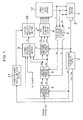
- FIG. 1 shows a system configuration for an inverter device according to the first embodiment.
- the inverter device which is configured to drive an electric motor 1, includes a rotation-angle detector 2, a rotational-speed calculation section 3, three-phase/two-phase conversion section 4, a current-instruction generation section 5, a voltage-instruction generation section 6, a two-phase/three-phase conversion section 7, a PWM-waveform generation section 8, a carrier-frequency calculation section 9, a carrier-frequency switching section 10, and a carrier-frequency switching limitation section 11.
- the rotation-angle detector 2 includes, for example, a resolver to detect the rotation angle ⁇ of the electric motor 1 to be driven.
- the rotational-speed calculation section 3 calculates an electric-motor rotational speed ⁇ from the rotation angle ⁇ detected by the rotation-angle detector 2.
- the three-phase/two-phase conversion section 4 converts three phase currents iu, iv, and iw into a d-axis current id and a q-axis actual current iq on the basis of the electric-motor-rotation angle ⁇ .
- the current-instruction generation section 5 outputs a d-axis current instruction Id and a q-axis current instruction Iq on the basis of a torque instruction and the electric-motor rotational speed ⁇ .
- the voltage-instruction generation section 6 calculates a d-axis voltage instruction Vd and a q-axis voltage instruction Vq on the basis of both d-axis current id and q-axis actual current iq and both d-axis current instruction Id and a q-axis current instruction Iq.
- the two-phase/three-phase conversion section 7 converts the d-axis voltage instruction Vd and the q-axis voltage instruction Vq into three phrase voltages Vu, Vv, and Vw on the basis of the electric-motor-rotation angle ⁇ .
- the carrier-frequency calculation section 9 calculates the carrier frequency on the basis of a plurality of elements.
- the carrier-frequency switching section 10 switches the carrier frequency of a PWM pulse generated by the PWM-waveform generation section 8 on the basis of the carrier frequency calculated by the carrier-frequency calculation section 9.
- the rotational-speed calculation section 3 also serves as a rotational-angular acceleration calculation section which calculates the rotational angular acceleration of the electric motor 1.
- the carrier-frequency switching limitation section 11 determines whether or not the carrier frequency should be permitted to be switched, on the basis of the rotational angular acceleration (d ⁇ /dt) of the electric motor 1 determined on the basis of the rotational speed calculated by the rotational-speed calculation section 3.
- the carrier-frequency switching limitation section 11 determines that the carrier frequency should not be changed because a rapid change in speed has been made, thus inputting, to the carrier-frequency switching section 10, a frequency switching limitation instruction to prohibit the carrier-frequency switching section 10 from a frequency switching process in accordance with the electric motor speed to make the carrier-frequency switching section 10 fix the carrier frequency to, for example, a value which enables control stability to be ensured at the maximum rotational speed of the electric motor 1.
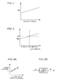
- FIG. 3 shows a relationship between the electric-motor rotational speed ⁇ and a fundamental carrier frequency fco to be determined in association with the electric-motor rotational speed ⁇ .
- the gain ⁇ is set so as to maximize the fundamental carrier frequency fco at an electric motor maximum rotational speed ⁇ max and decreases it in proportion to a decrease in the rotational speed.
- the carrier-frequency calculation section 9 performs: pre-storing, as a frequency characteristic, the most suitable relationship between the electric-motor rotational speed ⁇ and the fundamental carrier frequency fco for establishing both control stability and inverter efficiency; calculating the fundamental carrier frequency fco for each speed on the basis of the frequency characteristic; and finally calculating the actual carrier frequency fc by incorporating the output torque and the load inertia into the fundamental carrier frequency fco.
- the output torque gain Gt shown in FIG. 4 and the load inertia gain Ga shown in FIG. 5 are set so as to be increased with the increase in the output torque and load inertia, respectively.
- the carrier-frequency switching section 10 outputs the carrier frequency fc determined by the carrier-frequency calculation section 9 to the PWM-waveform generation section 8.
- the PWM-waveform generation section 8 Upon receiving the output, the PWM-waveform generation section 8 generates a PWM waveform (a pulse) corresponding to the carrier frequency fc and inputs the PWM waveform to a power supply/gate circuit 12, a narrowly- defined inverter.
- the power supply/gate circuit 12 inputs an AC voltage based on the PWM waveform into the electric motor 1.
- the required carrier frequency for ensuring control stability is decreased with decrease in the electric-motor rotational speed; and the lower carrier frequency involves a less inverter loss (a switching loss) to thus increase inverter efficiency. This enables both control stability and efficiency to be achieved throughout the entire speed region.
- the inverter device determines the actual carrier frequency fc by multiplying the fundamental carrier frequency fco determined from the electric-motor rotational speed by the gains Gt and Ga depending on the output torque of the electric motor and the load inertia.
- the actual carrier frequency fc is determined by taking into account the operating status of a machine provided with the electric motor 1. This allows preferable machine operations to be achieved. For example, when the load inertia or the output torque is great, there is performed a determination of the carrier frequency with priority given to the inverter efficiency, because a certain amount of fluctuation in torque involves no shock (no degradation of the control stability). On the other hand, when the load inertia or the output torque is low to make the response of the machine operation sensitive to a fluctuation in torque, the carrier frequency is gradually changed to thereby suppress a possible shock.
- the carrier-frequency switching limitation section 11 stops switching the carrier frequency. In other words, when the change in the speed of the electric motor is significant, the carrier-frequency switching limitation section 11 prohibits the carrier frequency from being switched. This allows the control to be stabilized.
- the total region of the electric-motor rotational speed is divided into a plurality of speed zones.
- the carrier-frequency switching section 10 among of them is configured to switch the carrier frequency in a step-by-step manner for each of the speed zones.
- the carrier-frequency switching section 10 pre-stores a plurality of carrier frequencies fc provided for respective zones of the electric-motor rotational speed as shown in FIG. 6A , and invokes one of the plurality of carrier frequencies fc, the invoked one corresponding to a speed zone to which the detected electric-motor rotational speed ⁇ belongs, to output it, as "frequency condition determination" shown in FIG. 6B .
- such hysteresis as shown in FIG. 6A is applied to the step-by-step switching of the carrier frequency.
- the carrier frequency can be determined by use of a little calculation and the control is facilitated, compared to the case of consecutively calculating the carrier frequency for each of all the electric-motor rotational speeds to switch it. Furthermore, the application of the hysteresis to the switching of the carrier frequency suppresses possible chattering near each switching point to enable smooth control to be performed.
- a third embodiment of the present invention will be described with reference to FIG. 7 .
- a region of the electric-motor rotational speed with a high output frequency is preset to be a high-frequency output region, in which the carrier frequency is switched more finely than in the other regions.
- FIG. 7 shows a case of frequent use of the electric-motor rotational speed and output torque in a region As corresponding to a certain speed zone ⁇ s and a certain torque region Ts, in which case the region As is subdivided into a plurality of use regions A1 to A6 and the carrier-frequency calculation section 9 stores a plurality of carrier frequencies assigned to the use regions A1 to A6, respectively, and switches among the carrier frequencies. This allows control in a frequently used region to be further stabilized and enables efficiency to be enhanced.
- the inverter device according to the present invention is applicable to driving of various electric motors, being particularly useful for driving an electric motor for a construction machine.
- FIG. 8 shows an excavator, an example of a slewing-type construction machine equipped with the inverter device according to the present invention and a slewing electric motor to be driven by the inverter device.
- the excavator includes a lower traveling body 13 of a crawler type, an upper slewing body 14 mounted on the lower traveling body 13 so as to be slewable around an axis X perpendicular to the ground, a front attachment 15 attached to the upper slewing body 14 to perform operations such as excavation, and a not-graphically-shown slewing electric motor which slews the upper slewing body.
- the slewing electric motor is driven by the inverter device according to the present invention.
- the present invention is not limited to the embodiments.
- the carrier frequency determined from the electric-motor rotational speed is multiplied by the gains depending on the load inertia and the output torque to calculate the actually used carrier frequency
- the carrier frequency determined from the electric-motor rotational speed may be multiplied by the gain depending on only one of either the load inertia or the output torque.
- the first embodiment sets the fundamental carrier frequency fco changing linearly at a constant gradient with respect to the electric-motor rotational speed ⁇ as shown in FIG. 3
- the specific relationship between the electric-motor rotational speed ⁇ and the fundamental carrier frequency fco is not limited.
- the relationship between the electric-motor rotational speed ⁇ and the fundamental carrier frequency fco may be expressed by polygonal lines corresponding to a combination of a plurality of lines with different gradients.
- the present invention provides an inverter device for driving an electric motor, which allows both control stability and efficiency to be ensured over a wide region of speeds of the electric motor.
- This inverter device includes a PWM-waveform generation section which generates a waveform for performing PWM control on the electric motor, a rotational-speed detection section which detects a rotational speed of the electric motor, a carrier-frequency calculation section which calculates a carrier frequency on the basis of the detected rotational speed, and a carrier-frequency switching section which switches the carrier frequency of the waveform generated by the PWM-waveform generation section, on the basis of the calculated carrier frequency.
- the carrier-frequency calculation section calculates, as the carrier frequency, a frequency which is increased with increase in the electric-motor rotational speed detected by the rotational-speed detection section.
- inverter device calculated is a carrier frequency which is decreased with decrease in the electric-motor rotational speed throughout the entire speed region, with focus placed on the following two points: (i) the required carrier frequency for ensuring control stability is decreased with decrease in the electric-motor rotational speed; and (ii) the lower carrier frequency involves a less inverter loss (a switching loss) to thus increase inverter efficiency.
- This enables both stabilization of control and improvement of efficiency to be achieved over a wide region, preferably over the entire region of the electric-motor rotational speed.
- the carrier-frequency calculation section pre-stores the most suitable frequency characteristic for ensuring both control stability and inverter efficiency, that is, the relationship between the electric-motor rotational speed and the carrier frequency, and determines the carrier frequency for each speed (or each speed region) on the basis of the frequency characteristic.
- the carrier-frequency calculation section preferably calculates the fundamental carrier frequency on the basis of the electric-motor rotational speed, and calculates the carrier frequency to be actually used by multiplying the fundamental carrier frequency by the gain depending on at least one of an output torque from the electric motor and a load inertia.
- determining the actual carrier frequency taking into account the output torque or load inertia, which is indicative of the operating status of the machine with the electric motor mounted therein, enables preferable machine operation to be achieved. For example, when the load inertia or the output torque is so high as to involve no shock even with a certain amount of fluctuation in torque, that is, involve no degradation of the control stability, the carrier frequency is determined with priority given to the inverter efficiency. On the other hand, when the load inertia or the output torque is so low as to make the response of machine operation to a fluctuation in torque be sensitive, gradually changing the carrier frequency allows a possible shock to be suppressed.
- the inverter device further includes a rotational-angular-acceleration calculation section which calculates the rotational angular acceleration of the electric motor, and a carrier-frequency switching limitation section that stops frequency switching performed by the carrier-frequency switching section when the rotational angular acceleration calculated by the rotational-angular-acceleration calculation section exceeds a set value.
- a rotational-angular-acceleration calculation section which calculates the rotational angular acceleration of the electric motor
- a carrier-frequency switching limitation section that stops frequency switching performed by the carrier-frequency switching section when the rotational angular acceleration calculated by the rotational-angular-acceleration calculation section exceeds a set value.
- the carrier-frequency calculation section preferably switches the carrier frequency more finely in a high-frequency output region that involves a higher output frequency than in the other regions in the relationship between the electric-motor rotational speed and an inverter output. This enables the stability and efficiency of control in a frequently used region to be enhanced.
- the carrier-frequency switching section preferably switches the carrier frequency in a step-by-step manner for each of a plurality of zones obtained by dividing an entire region of the electric-motor rotational speed in advance.
- the step-by-step switching of the carrier frequency makes it possible to determine the carrier frequency with a little calculation to facilitate control, compared to the case of consecutively calculating the carrier frequency for each of all the electric-motor rotational speeds and switching it.
- hysteresis is applied to the step-by-step switching of the carrier frequency performed by the carrier-frequency switching section.
- the application of the hysteresis suppresses possible chattering near each switching point to enable smooth control to be performed.
- the present invention also provides a slewing-type construction machine including a lower traveling body, an upper slewing body mounted on the lower traveling body so as to be slewable, a slewing electric motor which slews the upper slewing body, and the inverter device used to drive the slewing electric motor.
- An object of the present invention is to provide an inverter device for driving an electric motor, which allows control stability and efficiency to be ensured over a wide region of the speed of the electric motor.
- the inverter device includes a rotational-speed detection section which detects a rotational speed of the electric motor, a carrier-frequency calculation section which calculates a carrier frequency on the basis of the detected rotational speed, and a carrier-frequency switching section which switches, on the basis of the calculated carrier frequency, the carrier frequency used for performing PWM control on the electric motor.
- the carrier-frequency calculation section calculates, as the carrier frequency, a frequency increased with an increase in the electric-motor rotational speed detected by the rotational-speed detection section.
Landscapes
- Engineering & Computer Science (AREA)
- Power Engineering (AREA)
- Control Of Ac Motors In General (AREA)
Applications Claiming Priority (1)
| Application Number | Priority Date | Filing Date | Title |
|---|---|---|---|
| JP2013113976A JP6184753B2 (ja) | 2013-05-30 | 2013-05-30 | 電動機駆動用インバータ装置 |
Publications (2)
| Publication Number | Publication Date |
|---|---|
| EP2809001A2 true EP2809001A2 (de) | 2014-12-03 |
| EP2809001A3 EP2809001A3 (de) | 2015-09-09 |
Family
ID=50721674
Family Applications (1)
| Application Number | Title | Priority Date | Filing Date |
|---|---|---|---|
| EP14168574.3A Withdrawn EP2809001A3 (de) | 2013-05-30 | 2014-05-16 | Wechselrichtervorrichtung zum Antreiben eines elektrischen Motors |
Country Status (5)
| Country | Link |
|---|---|
| US (1) | US9276508B2 (de) |
| EP (1) | EP2809001A3 (de) |
| JP (1) | JP6184753B2 (de) |
| KR (1) | KR102278986B1 (de) |
| CN (1) | CN104218869B (de) |
Cited By (2)
| Publication number | Priority date | Publication date | Assignee | Title |
|---|---|---|---|---|
| EP3051691A1 (de) * | 2015-02-02 | 2016-08-03 | LG Electronics Inc. | Motorantriebsvorrichtung und wäschebehandlungsvorrichtung damit |
| WO2018024571A1 (en) * | 2016-08-03 | 2018-02-08 | Arcelik Anonim Sirketi | Household appliance having a power module with continuous and discontinuous pwm control |
Families Citing this family (12)
| Publication number | Priority date | Publication date | Assignee | Title |
|---|---|---|---|---|
| US9923447B2 (en) * | 2013-05-27 | 2018-03-20 | Kabushiki Kaisha Toshiba | Power conversion device having improved noise characteristics, and control method thereof |
| KR102220911B1 (ko) * | 2014-01-06 | 2021-02-25 | 엘지전자 주식회사 | 냉장고, 및 홈 어플라이언스 |
| JP6425819B2 (ja) * | 2015-08-12 | 2018-11-21 | 三菱電機株式会社 | 電動機駆動装置および冷凍空調装置 |
| GB2565271A (en) * | 2017-07-25 | 2019-02-13 | Quepal Ltd | A motor controller |
| JP6937708B2 (ja) * | 2018-02-21 | 2021-09-22 | 日立Astemo株式会社 | モータ制御装置およびそれを用いる電動車両システム |
| MX2020012658A (es) | 2018-07-02 | 2021-02-02 | Nippon Steel Corp | Metodo de ajuste de la frecuencia de la portadora, sistema de accionamiento del motor y dispositivo de ajuste de la frecuencia de la portadora. |
| DE102019120438A1 (de) * | 2019-07-29 | 2021-02-04 | Valeo Siemens Eautomotive Germany Gmbh | Steuereinrichtung, Wechselrichter, Anordnung mit einem Wechselrichter und einer elektrischen Maschine, Verfahren zum Betreiben eines Wechselrichters sowie Computerprogramm |
| DE102019120439A1 (de) * | 2019-07-29 | 2021-02-04 | Valeo Siemens Eautomotive Germany Gmbh | Steuereinrichtung, Wechselrichter, Anordnung mit einem Wechselrichter und einer elektrischen Maschine, Verfahren zum Betreiben eines Wechselrichters sowie Computerprogramm |
| JP7213448B2 (ja) * | 2019-12-26 | 2023-01-27 | 株式会社豊田自動織機 | 電動機の制御装置 |
| CN111416565B (zh) * | 2020-03-27 | 2023-07-04 | 四川长虹精密电子科技有限公司 | 变载波频率的电机控制装置及方法 |
| CN113179053B (zh) * | 2021-06-16 | 2022-05-13 | 国华(青岛)智能装备有限公司 | 一种同步电机控制方法 |
| CN115566962A (zh) * | 2022-09-30 | 2023-01-03 | 东风商用车有限公司 | 一种电机载波频率的控制方法 |
Citations (1)
| Publication number | Priority date | Publication date | Assignee | Title |
|---|---|---|---|---|
| JP2009291019A (ja) | 2008-05-30 | 2009-12-10 | Toyota Motor Corp | 交流モータ用インバータの制御装置 |
Family Cites Families (15)
| Publication number | Priority date | Publication date | Assignee | Title |
|---|---|---|---|---|
| JP3837986B2 (ja) * | 1999-12-24 | 2006-10-25 | 三菱電機株式会社 | 永久磁石形モータ、永久磁石形モータの制御方法、永久磁石形モータの制御装置、圧縮機、冷凍・空調装置。 |
| JP2002125362A (ja) * | 2000-10-17 | 2002-04-26 | Meidensha Corp | 半導体電力変換装置における主回路素子寿命の改善方法 |
| JP4352883B2 (ja) * | 2003-12-09 | 2009-10-28 | パナソニック株式会社 | ブラシレスdcモータの駆動方法及び駆動装置 |
| JP2006000731A (ja) * | 2004-06-16 | 2006-01-05 | Hitachi Koki Co Ltd | モータ制御装置および該制御装置を用いた遠心機 |
| JP2006333572A (ja) | 2005-05-24 | 2006-12-07 | Daihatsu Motor Co Ltd | 車両の電力変換装置及びそのキャリア周波数制御方法 |
| JP4736875B2 (ja) * | 2006-03-14 | 2011-07-27 | 株式会社デンソー | ファンモータ駆動装置及びファンモータ駆動方法 |
| JP4100442B2 (ja) * | 2006-09-29 | 2008-06-11 | ダイキン工業株式会社 | モータ駆動制御装置ならびにモータの駆動制御システム |
| JP4978429B2 (ja) * | 2007-11-01 | 2012-07-18 | アイシン・エィ・ダブリュ株式会社 | 電動機制御装置,電気自動車およびハイブリッド電気自動車 |
| JP4424421B2 (ja) * | 2008-01-17 | 2010-03-03 | トヨタ自動車株式会社 | 電動車両の制御装置およびそれを備えた電動車両、ならびに電動車両の制御方法およびその制御方法をコンピュータに実行させるためのプログラムを記録したコンピュータ読取可能な記録媒体 |
| JP5236965B2 (ja) * | 2008-02-29 | 2013-07-17 | 三菱重工業株式会社 | モータの制御装置 |
| JP5412750B2 (ja) | 2008-05-26 | 2014-02-12 | トヨタ自動車株式会社 | 動力装置 |
| JP4605274B2 (ja) * | 2008-08-27 | 2011-01-05 | トヨタ自動車株式会社 | 車両 |
| JP2010209637A (ja) * | 2009-03-12 | 2010-09-24 | Kobelco Contstruction Machinery Ltd | 電動旋回式作業機械のブレーキ装置 |
| JP5682744B2 (ja) * | 2010-03-17 | 2015-03-11 | コベルコ建機株式会社 | 作業機械の旋回制御装置 |
| DE102011003559A1 (de) * | 2011-02-03 | 2012-08-09 | Robert Bosch Gmbh | Verfahren und Vorrichtung zur Steuerung eines Pulswechselrichters, welcher zur Steuerung einer elektrischen Maschine dient |
-
2013
- 2013-05-30 JP JP2013113976A patent/JP6184753B2/ja not_active Expired - Fee Related
-
2014
- 2014-05-16 EP EP14168574.3A patent/EP2809001A3/de not_active Withdrawn
- 2014-05-27 KR KR1020140063621A patent/KR102278986B1/ko not_active Expired - Fee Related
- 2014-05-29 US US14/289,760 patent/US9276508B2/en not_active Expired - Fee Related
- 2014-05-30 CN CN201410238898.6A patent/CN104218869B/zh not_active Expired - Fee Related
Patent Citations (1)
| Publication number | Priority date | Publication date | Assignee | Title |
|---|---|---|---|---|
| JP2009291019A (ja) | 2008-05-30 | 2009-12-10 | Toyota Motor Corp | 交流モータ用インバータの制御装置 |
Cited By (4)
| Publication number | Priority date | Publication date | Assignee | Title |
|---|---|---|---|---|
| EP3051691A1 (de) * | 2015-02-02 | 2016-08-03 | LG Electronics Inc. | Motorantriebsvorrichtung und wäschebehandlungsvorrichtung damit |
| US20160226426A1 (en) * | 2015-02-02 | 2016-08-04 | Lg Electronics Inc. | Motor driving device and laundry treatment apparatus including the same |
| US9973131B2 (en) | 2015-02-02 | 2018-05-15 | Lg Electronics Inc. | Motor driving device and laundry treatment apparatus including the same |
| WO2018024571A1 (en) * | 2016-08-03 | 2018-02-08 | Arcelik Anonim Sirketi | Household appliance having a power module with continuous and discontinuous pwm control |
Also Published As
| Publication number | Publication date |
|---|---|
| KR20140141484A (ko) | 2014-12-10 |
| EP2809001A3 (de) | 2015-09-09 |
| JP6184753B2 (ja) | 2017-08-23 |
| US20140354191A1 (en) | 2014-12-04 |
| CN104218869A (zh) | 2014-12-17 |
| CN104218869B (zh) | 2018-07-27 |
| JP2014233178A (ja) | 2014-12-11 |
| US9276508B2 (en) | 2016-03-01 |
| KR102278986B1 (ko) | 2021-07-16 |
Similar Documents
| Publication | Publication Date | Title |
|---|---|---|
| US9276508B2 (en) | Inverter device for driving electric motor | |
| EP2953261B1 (de) | Synchrone motorsteuerungsvorrichtung für ein elektrofahrzeug | |
| EP2190112B1 (de) | Vorrichtung und Verfahren zum Steuern eines Wechselstrommotors | |
| EP1729407B1 (de) | Steuerung eines permanentmagnet-synchronmotors | |
| EP3509210B1 (de) | Wandlersteuerungsvorrichtung und elektromotorantriebssystem | |
| US9548688B2 (en) | Motor control apparatus | |
| US8823300B2 (en) | Electric motor control device | |
| JP5351002B2 (ja) | モータ制御装置 | |
| CN104335476A (zh) | 电动机的控制装置以及电动机的控制方法 | |
| JP6078282B2 (ja) | 交流電動機駆動システム及び電動機車両 | |
| CN104981974B (zh) | 逆变器装置、建筑机械和电动机控制方法 | |
| JP2010200430A (ja) | 電動機の駆動制御装置 | |
| EP1768252B1 (de) | Motorregeleinrichtung zur anbringung an einem fahrzeug | |
| US11597431B2 (en) | Motor control device | |
| EP3771088B1 (de) | Steuergerät für elektrischen permanentmagnet-synchronmotor | |
| EP2752986A1 (de) | Umrichtervorrichtung | |
| US8022659B2 (en) | Control apparatus for AC rotary machine and control method for AC rotary machine | |
| JP4931105B2 (ja) | 電気自動車用電力変換装置 | |
| JP5595436B2 (ja) | モータ制御装置 | |
| JP2003033071A (ja) | モータ制御装置 | |
| JP5325556B2 (ja) | モータ制御装置 | |
| US11611292B2 (en) | Power conversion device | |
| EP2782242B1 (de) | Steuervorrichtung für wechselstromdrehmaschine, und elektrische servolenkung mit steuervorrichtung für wechselstromdrehmaschine | |
| JP5595437B2 (ja) | モータ制御装置 | |
| JP5538657B2 (ja) | モータ制御装置 |
Legal Events
| Date | Code | Title | Description |
|---|---|---|---|
| PUAI | Public reference made under article 153(3) epc to a published international application that has entered the european phase |
Free format text: ORIGINAL CODE: 0009012 |
|
| 17P | Request for examination filed |
Effective date: 20140516 |
|
| AK | Designated contracting states |
Kind code of ref document: A2 Designated state(s): AL AT BE BG CH CY CZ DE DK EE ES FI FR GB GR HR HU IE IS IT LI LT LU LV MC MK MT NL NO PL PT RO RS SE SI SK SM TR |
|
| AX | Request for extension of the european patent |
Extension state: BA ME |
|
| PUAL | Search report despatched |
Free format text: ORIGINAL CODE: 0009013 |
|
| AK | Designated contracting states |
Kind code of ref document: A3 Designated state(s): AL AT BE BG CH CY CZ DE DK EE ES FI FR GB GR HR HU IE IS IT LI LT LU LV MC MK MT NL NO PL PT RO RS SE SI SK SM TR |
|
| AX | Request for extension of the european patent |
Extension state: BA ME |
|
| RIC1 | Information provided on ipc code assigned before grant |
Ipc: H02P 27/08 20060101AFI20150731BHEP |
|
| R17P | Request for examination filed (corrected) |
Effective date: 20160129 |
|
| RBV | Designated contracting states (corrected) |
Designated state(s): AL AT BE BG CH CY CZ DE DK EE ES FI FR GB GR HR HU IE IS IT LI LT LU LV MC MK MT NL NO PL PT RO RS SE SI SK SM TR |
|
| 17Q | First examination report despatched |
Effective date: 20170310 |
|
| STAA | Information on the status of an ep patent application or granted ep patent |
Free format text: STATUS: THE APPLICATION HAS BEEN WITHDRAWN |
|
| 18W | Application withdrawn |
Effective date: 20170522 |