EP2808951A1 - Anschlussblock und Verfahren zur Herstellung davon - Google Patents
Anschlussblock und Verfahren zur Herstellung davon Download PDFInfo
- Publication number
- EP2808951A1 EP2808951A1 EP14001640.3A EP14001640A EP2808951A1 EP 2808951 A1 EP2808951 A1 EP 2808951A1 EP 14001640 A EP14001640 A EP 14001640A EP 2808951 A1 EP2808951 A1 EP 2808951A1
- Authority
- EP
- European Patent Office
- Prior art keywords
- terminal
- housing
- conductive member
- socket
- sub
- Prior art date
- Legal status (The legal status is an assumption and is not a legal conclusion. Google has not performed a legal analysis and makes no representation as to the accuracy of the status listed.)
- Withdrawn
Links
Images


Classifications
-
- H—ELECTRICITY
- H01—ELECTRIC ELEMENTS
- H01R—ELECTRICALLY-CONDUCTIVE CONNECTIONS; STRUCTURAL ASSOCIATIONS OF A PLURALITY OF MUTUALLY-INSULATED ELECTRICAL CONNECTING ELEMENTS; COUPLING DEVICES; CURRENT COLLECTORS
- H01R9/00—Structural associations of a plurality of mutually-insulated electrical connecting elements, e.g. terminal strips or terminal blocks; Terminals or binding posts mounted upon a base or in a case; Bases therefor
- H01R9/22—Bases, e.g. strip, block, panel
- H01R9/24—Terminal blocks
- H01R9/2491—Terminal blocks structurally associated with plugs or sockets
-
- H—ELECTRICITY
- H01—ELECTRIC ELEMENTS
- H01R—ELECTRICALLY-CONDUCTIVE CONNECTIONS; STRUCTURAL ASSOCIATIONS OF A PLURALITY OF MUTUALLY-INSULATED ELECTRICAL CONNECTING ELEMENTS; COUPLING DEVICES; CURRENT COLLECTORS
- H01R13/00—Details of coupling devices of the kinds covered by groups H01R12/70 or H01R24/00 - H01R33/00
- H01R13/73—Means for mounting coupling parts to apparatus or structures, e.g. to a wall
- H01R13/74—Means for mounting coupling parts in openings of a panel
-
- H—ELECTRICITY
- H01—ELECTRIC ELEMENTS
- H01R—ELECTRICALLY-CONDUCTIVE CONNECTIONS; STRUCTURAL ASSOCIATIONS OF A PLURALITY OF MUTUALLY-INSULATED ELECTRICAL CONNECTING ELEMENTS; COUPLING DEVICES; CURRENT COLLECTORS
- H01R13/00—Details of coupling devices of the kinds covered by groups H01R12/70 or H01R24/00 - H01R33/00
- H01R13/02—Contact members
- H01R13/10—Sockets for co-operation with pins or blades
- H01R13/11—Resilient sockets
- H01R13/111—Resilient sockets co-operating with pins having a circular transverse section
-
- H—ELECTRICITY
- H01—ELECTRIC ELEMENTS
- H01R—ELECTRICALLY-CONDUCTIVE CONNECTIONS; STRUCTURAL ASSOCIATIONS OF A PLURALITY OF MUTUALLY-INSULATED ELECTRICAL CONNECTING ELEMENTS; COUPLING DEVICES; CURRENT COLLECTORS
- H01R13/00—Details of coupling devices of the kinds covered by groups H01R12/70 or H01R24/00 - H01R33/00
- H01R13/46—Bases; Cases
- H01R13/502—Bases; Cases composed of different pieces
- H01R13/506—Bases; Cases composed of different pieces assembled by snap action of the parts
-
- H—ELECTRICITY
- H01—ELECTRIC ELEMENTS
- H01R—ELECTRICALLY-CONDUCTIVE CONNECTIONS; STRUCTURAL ASSOCIATIONS OF A PLURALITY OF MUTUALLY-INSULATED ELECTRICAL CONNECTING ELEMENTS; COUPLING DEVICES; CURRENT COLLECTORS
- H01R2201/00—Connectors or connections adapted for particular applications
- H01R2201/26—Connectors or connections adapted for particular applications for vehicles
Definitions
- the present invention relates to a terminal block and to a method of producing it.
- a terminal block for electrically connecting conductive members provided in electric devices such as a motor, an inverter and the like is known from Japanese Unexamined Patent Publication No. 2010-211933 .
- This includes a housing made of synthetic resin and to be mounted through a case of a specified device in an in-out direction and a plurality of terminals each configured such that a connecting portion with a nut is provided on each of opposite ends of an L-shaped busbar.
- the terminals are so structured that the connecting portions on one end side and those on the other end side are mounted side by side to be respectively located on an outer end part of the housing and in an inner end part of the housing.
- Outer conductive members formed of busbars extending from the electric device such as an inverter are bolted and connected to the outer connecting portions of the terminals mounted in the terminal block, and inner conductive members formed of busbars extending from the electric device such as a motor are likewise bolted and connected to the inner connecting portions of the terminals, whereby the corresponding inner and outer conductive members are electrically connected.
- the present invention was completed based on the above situation and aims to allow for a terminal block capable of realizing space saving and improving operability in connecting conductive members and terminals.
- a terminal block for connecting at least one inner conductive member and at least one outer conductive member arranged inside and outside a device, comprising: a housing which is provided to penetrate through a case of the device in an in-out direction; at least one terminal mountable in the housing and including a connecting portion to be connected to the outer conductive member and provided on an outer end part and a socket terminal to be fitted and connected to a pin terminal provided on the inner conductive member and provided on an inner end part; and at least one sub-housing in which the socket terminal is to be at least partly accommodated and on which at least one terminal insertion opening, into which the pin terminal is insertable, is open; wherein the sub-housing is to be mounted in the housing loosely movably in a direction intersecting with an axis of the socket terminal.
- the terminal block is provided for connecting a plurality of inner conductive members and a plurality of outer conductive member arranged inside and outside a device, comprising plural terminals each of which is mountable in the housing.
- a terminal block for connecting a plurality of inner conductive members and a plurality of outer conductive members arranged inside and outside a device, including a housing which is provided to penetrate through a case of the device in an in-out direction; terminals each of which is mounted in the housing and includes a connecting portion to be connected to the outer conductive member and provided on an outer end part and a tubular socket terminal to be fitted and connected to a pin terminal provided on the inner conductive member and provided on an inner end part; and sub-housings in which the socket terminals are accommodated and on which terminal insertion openings, into which the pin terminals are insertable, are open; wherein the sub-housings are mounted in the housing loosely movably in a direction intersecting with an axis.
- the pin terminal provided on the inner conductive member is fitted into the socket terminal accommodated in the sub-housing through the terminal insertion opening of the sub-housing in connecting the inner conductive member to the inner end part of the terminal.
- connection by bolting it suffices to fit the pin terminal into the socket terminal.
- a connecting operation itself is simple, a need for an operation space for bolting can be eliminated and space saving can be realized.
- the (particularly each) sub-housing adopts a so-called floating structure and is mounted in the housing, even if there is, for example, a variation in the arrangement positions of the respective inner conductive members, i.e. the respective pin terminals, the individual pin terminals and socket terminals can be precisely aligned with and fitted to each other while the sub-housings are loosely moved in a direction intersecting with a connection direction of individual pin terminals and socket terminals (or a longitudinal axis of the socket terminal).
- an easily bendable portion is provided at an intermediate position of the terminal in a length direction.
- the sub-housing can loosely move while deforming the terminal at the easily bendable portion and more reliably exhibit a floating function.
- the terminal includes at least one substantially strip-like portion and the easily bendable portion is formed or provided at an intermediate position of the strip-like portion in the length direction.
- the floating function can be more reliably exhibited while a simple structure is ensured for the terminal.
- the easily bendable portion in the terminal comprises or particularly is at lest one flexible conductor formed preferably by a braided wire.
- the floating function of the sub-housing can be more reliably exhibited.
- this vibration acts on the inner or outer conductive member, this vibration is absorbed by the flexible conductor and the transmission thereof to the opposite conductive member side is suppressed.
- the socket terminal is accommodated in an inner end part of the housing; and wherein at least one terminal insertion opening, into which the pin terminal is insertable, is provided on an outer surface of the housing to communicate with the socket terminal.
- At least one tapered guiding portion is formed on or near an opening edge part of the terminal insertion opening.
- the housing includes a housing main body molded with an opening formed on the side of the socket terminal of the terminal and a cover to be mounted on the opening of the housing main body to at least partly cover the socket terminal
- the terminal insertion opening is formed over the housing main body and the cover.
- the connecting portion has such a plural- or two-piece structure that a substantially tubular body is fitted on the outer periphery of a louver terminal portion.
- the louver terminal portion is shaped such that a plurality of resilient contact pieces, each particularly including a contact portion on or near a tip side and substantially extending forward, at least partly are arranged in a ring shape while being circumferentially spaced apart on the front edge of an annular base portion.
- a method of connecting an inner conductive member and an outer conductive member arranged inside and outside a device comprising the following steps: providing a housing to penetrate through a case of the device in an in-out direction; mounting at least one terminal in the housing and including a connecting portion to be connected to the outer conductive member and provided on an outer end part and a socket terminal at least partly accommodating the socket terminal at least one sub-housing, on which at least one terminal insertion opening is open, into which a pin terminal provided on the inner conductive member and provided on an inner end part is insertable, wherein the sub-housing is mounted in the housing loosely movably in a direction intersecting with an axis of the socket terminal; and fitting and connecting the at least one terminal to the pin terminal.
- a plurality of inner conductive members and a plurality of outer conductive member arranged inside and outside a device are connected by means of plural terminals each of which is mountable in the housing.
- an easily bendable portion is provided at an intermediate position of the terminal in a length direction.
- the terminal includes at least one substantially strip-like portion and the easily bendable portion is formed or provided at an intermediate position of the strip-like portion in the length direction and/or wherein the easily bendable portion in the terminal comprises at least one flexible conductor preferably formed by a braided wire.
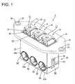
- FIGS. 1 to 6 A first particular embodiment of the present invention is described with reference to FIGS. 1 to 6 .
- a terminal block T for electrically connecting one or more conductive members, e.g. three conductive members provided in a three-phase alternating current motor mounted in a vehicle such as an electric vehicle or a hybrid vehicle and one or more respective mating conductive members, e.g. three conductive members provided in an inverter.
- the terminal block T is applied in a case where the motor and the inverter are directly coupled.
- the terminal block T is to be provided on a lateral wall (e.g. an upper wall) 2 of a transmission case 1 (as a particular electric or electronic device) and an unillustrated motor-side case is adjacently assembled particularly on a front opening side (left side in FIG. 5 ) of the transmission case 1, whereas an inverter-side case is assembled on the lateral (e.g. upper) surfaces of the integrally joined transmission case and motor-side case.
- the three conductive members (as a particular inner conductive member) extending from the motor and the conductive members (as a particular outer conductive member) extending from the inverter are to be electrically connected via the terminal block T as described above.
- the outer conductive member(s) extending from the inverter are one o more busbars
- the inner conductive members extending from the motor are obtained by wires, particularly by solidifying enamel wires in a substantially straight posture using an adhesive or the like, and one or more (particularly substantially round) pin terminals p are to be substantially coaxially connected on the tip(s) of the inner conductive member(s) as shown in FIG. 5 .
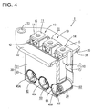
- the terminal block T includes one or more, particularly shown three terminals 10 and a housing 30 which is made e.g. of synthetic resin and in which one or more, particularly these three terminals 10 are to be mounted particularly side by side.
- the terminal 10 particularly is structured such that a (particularly substantially strip-like) piece 12 made of a conductive member (particularly a metal plate) thinner than a busbar 11 bent particularly substantially into an L shape is connected to a hanging or distal end of the busbar 11.
- the strip-like piece 12 particularly is bent into a crank shape for reinforcement and the like at an intermediate position in a longitudinal or height direction.
- a (particularly substantially horizontal) part of the busbar 11 which is one end side of the terminal 10 serves as an outer connecting portion 14 to be connected to the outer conductive member and particularly is formed with an insertion hole 15 for a bolt.
- a socket terminal 20 which functions as an inner connecting portion to be connected to the inner conductive member is provided on another end (particularly a distal or lower end) of the (strip-like) piece 12 which is the other end side of the terminal 10.
- This socket terminal 20 particularly has such a plural- or two-piece structure that a substantially tubular body 25 is fitted on the outer periphery of a louver terminal portion 21.
- the louver terminal portion 21 is shaped such that a plurality of resilient contact pieces 23 each including a contact portion 23A on or near a tip side and substantially extending forward at least partly are arranged in a ring shape while being circumferentially spaced apart on the front edge of an annular base portion 22.
- a rear edge part of the lower surface of the base portion 22 is bent outward to form a projection 22A.
- a jaw portion 26 (shown in Fig. 6 ) substantially facing inward to protect the tips of the resilient contact pieces 23 of the louver terminal portion 21 is formed on or near the front end of the tubular body 25.
- the lower surface of the tubular body 25 particularly is cut from the rear edge to form at least one groove 28 into which the above projection 22A at least partly is insertable.
- the tubular body 25 is to be fitted onto or connected with (particularly the outer periphery of) the louver terminal portion 21 particularly substantially from front, the pushing thereof particularly is stopped when the projection 22A comes into contact with the back edge of the groove 28, and/or the tubular body 25 particularly is retained and mounted by bending or folding back one or more, particularly a pair of joining pieces 27 projecting from the rear edge onto the base portion 22.
- the above (particularly substantially strip-like) piece 12 is integrally or unitarily erected from the upper or distal edge of the base portion 22 of the louver terminal portion 21, and an upper or distal end part of this strip-like piece 12 is placed in contact with the hanging or projecting end of the terminal 10 and fixed such as by spot welding, soldering, gluing, bolting or the like.
- the terminal 10 is formed, and the socket terminal 20 as the inner connecting portion is provided on a lower or distal end part of the terminal 10 in such a posture as to substantially face in the same direction (leftward direction of FIG. 6 ) as a bending direction of the outer connecting portion 14 of the terminal 10.
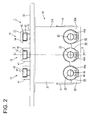
- a total of three terminals 10 are provided, and each terminal 10 is so mounted in the housing 30 that the socket terminal 20 is at least partly accommodated in a sub-housing 60 (see FIG. 5 ).
- the sub-housing 60 is described later.
- the housing 30 particularly is composed of or comprises a housing main body 31 and a cover 50.
- the housing main body 31 substantially is formed into a box shape having a lower surface opening long and narrow substantially in a lateral direction, a laterally long flange 32 is formed on the lateral or upper edge thereof, and one or more mounting holes 33, into which one or more collars 34 at least partly are fitted, are provided laterally of the flange 32, particularly on substantially opposite lateral (left and right) ends of this flange 32.
- a packing mounting groove 35 particularly is circumferentially provided on the lower surface of the flange 32, and an annular surface packing 36 is to be mounted thereinto.
- a seat block 40 on which the outer connecting portion(s) 14 of the respective terminal(s) 10 is/are mounted (particularly substantially side by side) is provided in a central or intermediate part of the lateral or upper surface of the housing main body 31.
- This seat block 40 is formed with one or more (e.g. three) seats 41 on which the outer connecting portions 14 are individually mounted, and the (particularly each) seat 41 is formed with an accommodating chamber 43 for a nut 42 which is recessed from a placing surface and substantially open forward.
- the nut 42 is to be at least partly accommodated in each accommodating chamber 43 with the displacement (particularly rotation) thereof prevented.
- the seat block 40 is formed over the one or more, particularly three terminals 10 arranged at specified (predetermined or predeterminable) intervals (including connected parts to the respective strip-like pieces 12) by primary molding, whereby the one or more, particularly three terminals 10 are held in specified (predetermined or predeterminable) postures on the seat block 40.
- the cover 50 particularly is formed separately from the housing main body 31 and/or substantially in the form of a rectangular deep dish to at least partly cover the aforementioned lateral or lower surface opening of the housing main body 31.
- one or more resiliently displaceable lock frames 51 are formed to rise on one or more lateral (left and/or right) side surfaces of the cover 50, whereas one or more lock projections 38 are provided on one or more lateral (left and/or right) side surfaces of the housing main body 31.
- the lock frame(s) 51 is/are resiliently fitted to the lock projection(s) 38, thereby forming the housing 30 in which the housing main body 31 and the cover 50 are integrally joined.
- the socket terminal 20 as the inner connecting portion of the terminal 10 is to be at least partly accommodated in the sub-housing 60.
- This sub-housing 60 is made e.g. of synthetic resin and particularly substantially formed into a hollow cylindrical shape which is provided with a front wall 61 and into which the socket terminal 20 is at least partly insertable particularly substantially from behind as shown in FIGS. 4 and 5 .
- the sub-housing 60 particularly has a length equivalent to a dimension of the housing main body 31 in a front-back direction, but a first part (particularly an upper half) is cut off in a length area (particularly having less than half the length) on a rear end side, thereby forming an escaping portion 62. In other words, only a semicylindrical portion 63 on a second part (particularly a lower half) is present on the rear end side of the sub-housing 60.
- a terminal insertion opening 65 into which the above (particularly substantially round) pin terminal p at least partly is insertable, is open on the front wall 61 of the sub-housing 60, and a guiding portion 66 widened toward a front side is formed in a front end part of the terminal insertion opening 65.
- a locking lance 67 for locking the projection 22A of the socket terminal 20 is resiliently deflectably provided on (particularly the bottom wall of) the sub-housing 60 particularly while substantially extending backward.
- the socket terminal 20 is to be at least partly inserted into the sub-housing 60 (particularly substantially from behind) and displaced or pushed while resiliently deflecting the locking lance 67.
- the projection 22A passes over a locking portion 67A of the locking lance 67 and the locking portion 67A is engaged with the projection 22A while the locking lance 67 at least partly is restored and displaced, whereby the socket terminal 20 is retained and accommodated in the sub-housing 60.
- a front rib 68 (particularly substantially having a constant height or projecting distance) is formed (particularly over the substantially entire circumference) on the outer periphery of a front end part of the sub-housing 60, specifically in a central or intermediate part of the front wall 61 in a thickness direction. Further, a rear rib 60 (particularly substantially having the same height as the front rib 68) is formed on the outer periphery of the semicylindrical portion 63 of the sub-housing 60.
- one or more fitting holes 45A into which front end part(s) (front wall(s) 61) of the sub-housing(s) 60 accommodating the above socket terminal(s) 20 is/are to be fitted are formed in positions corresponding to the terminal(s) 10 (socket terminal(s) 20) and/or at the same interval(s) as the terminal(s) 10 (socket terminal(s) 20) on a joint of the lower edge of the housing main body 31 and the upper edge of the cover 50 on the front surface of the housing 30.
- a fitting groove 46A into which the front rib 68 of the sub-housing 60 at least partly is to be fitted is formed over the entire circumference on the inner surface of each fitting hole 45A.
- each fitting hole 45A is formed on the (lower) edge of the front wall 31A of the housing main body 31 and a second part (particularly a lower half) thereof is formed on the (upper) edge of a front wall 50A of the cover 50.
- one or more (particularly substantially semicircular) fitting holes 45B into which rear end part(s) of the semicylindrical portion(s) 63 of the sub-housing(s) 60 is/are to be fitted are formed on (particularly the upper edge of a rear wall 50B of) the cover 50, and one or more fitting grooves 46B into which the rear rib(s) 69 of the sub-housing(s) 60 at least partly is/are to be fitted are formed on the inner surface(s) (particularly lower semi-circumferential surface(s)) of the fitting hole(s) 45B.
- An inner diameter of the fitting hole 45A on the front surface side of the housing 30 particularly is set to be larger than an outer diameter of the front end part of the sub-housing 60 by a fixed dimension and/or an inner diameter of the fitting groove 46A particularly is set to be larger than an outer diameter of the front rib 68 (particularly substantially by the same dimension).
- an inner diameter of the semicircular fitting hole 45B on the rear surface side of the housing 30 particularly is set to be larger than an outer diameter of the semicylindrical portion 63 of the sub-housing 60 (particularly substantially by the same dimension)
- an inner diameter of the fitting groove 46B particularly is set to be larger than an outer diameter of the rear rib 69 (particularly substantially by the same dimension).
- the housing main body 31 integrally including the one or more (e.g. three) terminals 10 is formed by two moldings as shown in FIG. 6 .
- the outer connecting portion 14 of each terminal 10 is placed on the corresponding seat 41 right above the accommodating chamber 43 for the nut 42 while being substantially held in a forward facing posture.
- the socket terminal 20 as the inner connecting portion of the (particularly each) terminal 10 particularly is located on the substantially same axis as the fitting hole 45A (precisely, upper half of this fitting hole 45A) behind the fitting hole 45A while being similarly substantially held in a forward facing posture.
- the one or more sub-housings 60 are mounted on the one or more socket terminals 20 as the inner connecting portion(s) of the one or more (e.g. three) terminals 10 integrally provided in the housing main body 31 in a manner already described above.
- the cover 50 is mounted on (particularly the lower surface opening of) the housing main body 31.
- the lock frame(s) 51 move(s) onto the lock projection(s) 38, is/are displaced or pushed up from below while being resiliently displaced, and is/are fitted to the lock projection(s) 38 while being restored into or towards an original shape when the upper edge of the cover 50 comes into contact with the lower edge of the housing main body 31, whereby the cover 50 is integrally joined and the housing 30 is formed as shown in FIG. 5 .
- the (particularly each) sub-housing 60 is fitted with a specified (predetermined or predeterminable) radial clearance formed between a front end part thereof and the fitting hole 45A on the front surface side of the housing 30 while the front rib 68 at least partly is fitted into the fitting groove 46A.
- the semicylindrical portion 63 of the sub-housing 60 is fitted with a specified (predetermined or predeterminable) radial clearance formed in the semicircular fitting hole 46B on the rear surface side of the housing 30 while the rear rib 69 at least partly is fitted into the fitting groove 46B.
- each sub-housing 60 is mounted in a lower end part of the housing 30 with movements thereof in an axial direction (front-back direction) restricted and with loose movements thereof in a direction (radial direction) intersecting with an axis allowed in the clearances.
- the nut 42 at least partly is inserted into the accommodating chamber 43 of each seat 41 on such a housing 30, and the surface packing 36 is mounted into the packing mounting groove 35 on the lower surface of the flange 32, whereby the terminal block T is completed.
- the terminal block T assembled as described above is mounted on (particularly the upper wall 2 of) the transmission case 1 as shown in FIG. 5 .
- the lower end part of the housing 30 at least partly is inserted into a through hole 3 open on the case upper wall 2 from above and, thereafter, one or more bolts are inserted into the mounting hole(s) 33 of the flange 32 and screwed into bolt hole(s) on the case upper wall 2, whereby the flange 32, i.e. the terminal block T is fixed to the case upper wall 2.
- the surface packing 36 is compressed and pressed against the hole edge of the through hole 3, thereby sealing the through hole 3.
- each terminal 10 When the terminal block T is mounted in this way, the outer connecting portion 14 of each terminal 10 is exposed on (particularly an upper or lateral surface side (outer side) of) the case upper wall 2 while being arranged on (particularly the upper surface of) the housing 30 (seat block 40).
- the socket terminal 20 as the inner connecting portion of each terminal 10 at least partly is accommodated in the sub-housing 60 supported loosely movably in the radial direction relative to the housing 30.
- the sub-housing 60 is arranged in a floating structure allowing for a displacement of the sub-housing 60 with respect to the housing 30 in a direction intersecting with a longitudinal axis of the socket terminal 20 so that a relative position of the socket terminal 20 with respect to the pin terminal p can be achieved.
- the terminal block T may be utilized for connecting any kind of conductive member with a respective mating conductive member irrespective of the given specific example of the three-phase alternating current motor and inverter.
- the one or more, particularly three inner conductive members (enamel wires) of the motor side are connected to the inner connecting portions of the corresponding terminals 10 by inserting the (particularly substantially round) pin terminal(s) p provided on the tip(s) of the (enamel) wire(s) into the socket terminal(s) 20 behind the terminal insertion opening(s) 65 of the sub-housing(s) 60 mounted in the lower end part of the housing 30 through the terminal insertion opening(s) 65 as indicated by an arrow in FIG. 5 .
- the sub-housing(s) 60 is/are moved in the radial direction for alignment while slightly deforming the (strip-like) piece(s) 12 of the terminal(s) 10 as the (round) terminal pin(s) p is/are inserted along the guiding portion(s) 66.
- the (particularly round) pin terminal(s) p is/are pushed or displaced while resiliently displacing the resilient contact piece(s) 23 of the louver terminal portion(s) 21.
- the resilient contact piece(s) 23 at least partly is/are restored in a diameter reducing direction, whereby the (round) pin terminal(s) p and the socket terminal(s) 20 are resiliently fitted into contact with each other and the one or more (e.g. three) inner conductive members (particularly enamel wires) of the motor side are connected to the inner connecting portion(s) (particularly socket terminal(s) 20) of the corresponding terminal(s) 10.
- the motor-side case is adjacently assembled to at least partly cover a front surface opening of the transmission case 1.
- the one or more, particularly three outer conductive members (busbars) of the inverter side are connected to the one or more respective outer connecting portions 14 of the one or more corresponding terminals 10.
- the respective busbars particularly are placed on the outer connecting portions 14 arranged substantially side by side on the upper surface of the housing 30, one or more bolts at least partly are inserted through the insertion holes of the busbars and the insertion holes 15 of the outer connecting portions 14 and threadably tightened into the respective nut(s) 42 at least partly accommodated in the accommodating chambers 43 with the displacement/rotation thereof prevented, whereby the one or more, particularly three outer conductive members (busbars) of the inverter side are connected to the one or more respective outer connecting portions 14 of the one or more corresponding terminals 10.
- the inverter-side case is assembled on the lateral or upper surface(s) of the transmission case 1 and the motor-side case integrally joined as described above.
- the three conductive members provided in the three-phase alternating current motor and those provided in the inverter are electrically connected via the terminal block T and a terminal connection structure of a type in which the motor and the inverter are directly coupled is constructed.
- parts for connecting the inner conductive member(s) of the motor side to the inner connecting portion(s) of the terminal(s) 10 mounted in or on the terminal block T are so structured that the (particularly round) pin terminal(s) p is/are provided on the inner conductive member(s) and, on the other hand, the inner connecting portion(s) of the terminal(s) 10 is/are formed by the socket terminal(s) 20.
- the connection of the inner conductive member(s) to the inner connecting portion(s) of the terminals 10 is realized by at least partly fitting the (round) pin terminal(s) p into the mating socket terminal(s) 20.
- the connecting operation itself is simple since it suffices to at least partly fit the (round) pin terminal(s) p into the socket terminal(s) 20. Further, space saving can be realized and, for example, the miniaturization of the motor case can be realized since a need for an operation space for bolting can be eliminated.
- the socket terminal(s) 20 of the respective terminal(s) 10 particularly is/are individually at least partly accommodated in the sub-housing(s) 60, whereas the respective sub-housing(s) 60 is/are mounted in the housing 30, loosely movably in the radial direction, i.e. adopting a so-called floating structure.
- the individual (round) pin terminal(s) p and socket terminal(s) 20 can be precisely aligned with and fitted or connected to each other while loosely moving the sub-housing(s) 60.
- a terminal block T for connecting one or more, particularly a plurality of inner conductive members and one or more, particularly a plurality of outer conductive members arranged inside and outside a device includes a housing 30 which is provided to penetrate through a case 2 of the device in an in-out direction, one or more terminals 10 each of which is mounted in the housing and includes a connecting portion 14 to be connected to the outer conductive member and provided on an outer end part and a (particularly substantially tubular) socket terminal 20 to be at least partly fitted and connected to a pin terminal p provided on the inner conductive member and provided on an inner end part, and one or more sub-housings in which the one or more socket terminals 20 at least partly are to be accommodated and on which one or more terminal insertion openings, into which the one or more respective pin terminals p at least partly are insertable, are open.
- the sub-housings 60 are to be mounted in the housing 30 loose
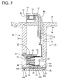
- a second particular embodiment of the present invention is described with reference to FIG. 7 .
- a terminal block T1 of this second embodiment is a modification of the first embodiment and similar to the first embodiment in that a terminal 70 is composed of or comprises a busbar 11 and a (particularly substantially strip-like) portion 71, but an easily bendable portion 72 projecting forward while being curved is formed at an intermediate position of the (strip-like) portion 71 in the height or extension direction.
- Other structures are similar or substantially the same as in the first embodiment.
- a sub-housing 60 can loosely move while deforming the terminal 70 at the easily bendable portion 72 and a floating function can be more reliably exhibited.
- FIG. 8 shows a third particular embodiment of the present invention.
- a change is made in the structure of a part where an easily bendable portion is provided on a terminal 80.
- the terminal 80 is so structured that at least one flexible conductor 81, which serves as the easily bendable portion, is connected to a hanging or projecting end of a busbar 11 particularly substantially bent into an L shape.
- This flexible conductor 81 particularly is structured by bending a braided wire into a substantially S shape or meander shape.
- a coupling piece 24 (particularly having a low height) is erected or projects from a base portion 22 of a louver terminal portion 21 in a socket terminal 20A which serves as an inner connecting portion.
- the flexible conductor 81 is placed in contact with (particularly the rear surface of a lower end part of) this busbar 11, and (particularly a lower end part of) this flexible conductor 81 is placed in contact with (particularly the front surface of an upper end part of) the coupling piece 24 erected or projecting from the base portion 22 of the louver terminal portion 21.
- the both end parts are fixed particularly by spot welding, soldering, gluing, bolting, or the like.
- a bending direction of an outer connecting portion 14 and a facing direction of the socket terminal 20AA particularly substantially are opposite in the front-back direction.
- this terminal 80 is mounted in a housing 30 after the socket terminal 20A as the inner connecting portion at least partly is accommodated in a sub-housing 60, and the sub-housing 60 is supported loosely movably substantially in a radial direction.
- the outer connecting portion of each terminal 80 is structured to be arranged in a backward facing posture on the upper surface of the housing 30 (seat block 40).
- this structure substantially is not functionally different from a case where each terminal 80 is set in a forward facing posture.
- the sub-housing 60 can loosely move while deforming the flexible conductor 81 of the terminal 80 and, similarly, the floating function can be more reliably exhibited.
- the flexible conductor(s) 81 provided in the terminal(s) 80 function(s) as vibration absorbing portion(s). If vibration acts on the inner or outer conductive member, this vibration is absorbed by the flexible conductor 81 and the transmission thereof to the opposite conductive member side is suppressed.
- the present invention is more effective when members having a high rigidity such as busbars are applied to the inner conductive members.
Landscapes
- Connections Arranged To Contact A Plurality Of Conductors (AREA)
- Connector Housings Or Holding Contact Members (AREA)
- Details Of Connecting Devices For Male And Female Coupling (AREA)
Applications Claiming Priority (1)
| Application Number | Priority Date | Filing Date | Title |
|---|---|---|---|
| JP2013113959A JP5979445B2 (ja) | 2013-05-30 | 2013-05-30 | 端子台 |
Publications (1)
| Publication Number | Publication Date |
|---|---|
| EP2808951A1 true EP2808951A1 (de) | 2014-12-03 |
Family
ID=50729331
Family Applications (1)
| Application Number | Title | Priority Date | Filing Date |
|---|---|---|---|
| EP14001640.3A Withdrawn EP2808951A1 (de) | 2013-05-30 | 2014-05-08 | Anschlussblock und Verfahren zur Herstellung davon |
Country Status (3)
| Country | Link |
|---|---|
| EP (1) | EP2808951A1 (de) |
| JP (1) | JP5979445B2 (de) |
| CN (1) | CN104218335B (de) |
Cited By (1)
| Publication number | Priority date | Publication date | Assignee | Title |
|---|---|---|---|---|
| FR3117282A1 (fr) * | 2020-12-08 | 2022-06-10 | Alstom Transport Technologies | Dispositif de raccordement haute tension pour véhicule de transport, notamment ferroviaire, caisse de véhicule et véhicule comprenant un tel dispositif |
Families Citing this family (3)
| Publication number | Priority date | Publication date | Assignee | Title |
|---|---|---|---|---|
| JP6881534B2 (ja) * | 2019-09-26 | 2021-06-02 | 住友電装株式会社 | 樹脂成形品 |
| JP7427341B2 (ja) | 2020-10-06 | 2024-02-05 | 日本航空電子工業株式会社 | 端子台 |
| JP2022083578A (ja) * | 2020-11-25 | 2022-06-06 | 住友電装株式会社 | コネクタ及びワイヤハーネス |
Citations (6)
| Publication number | Priority date | Publication date | Assignee | Title |
|---|---|---|---|---|
| JP2010211933A (ja) | 2009-03-06 | 2010-09-24 | Yazaki Corp | 防水端子台 |
| EP2413435A1 (de) * | 2009-03-25 | 2012-02-01 | Yazaki Corporation | Verbinder |
| US20120040553A1 (en) * | 2009-08-03 | 2012-02-16 | Yazaki Corporation | Floating connector with flexible conductive member |
| WO2012035030A1 (de) * | 2010-09-13 | 2012-03-22 | Hachadorian Design & Calculation Gmbh | Elektrischer kontakt |
| WO2012076983A1 (en) * | 2010-12-09 | 2012-06-14 | Fci Automotive Holding | Electrical connection device |
| US20130065426A1 (en) * | 2011-09-08 | 2013-03-14 | Hitachi Cable, Ltd. | Connector and wire harness |
Family Cites Families (5)
| Publication number | Priority date | Publication date | Assignee | Title |
|---|---|---|---|---|
| JP3425541B2 (ja) * | 1999-08-23 | 2003-07-14 | 株式会社オートネットワーク技術研究所 | シールドコネクタ |
| JP2004253163A (ja) * | 2003-02-18 | 2004-09-09 | Yazaki Corp | 中継端子及びコネクタ |
| JP5434612B2 (ja) * | 2010-01-14 | 2014-03-05 | トヨタ自動車株式会社 | 端末接続装置 |
| JP5721332B2 (ja) * | 2010-03-05 | 2015-05-20 | 矢崎総業株式会社 | モータケースに設置されたインバータ端子台 |
| JP2011204607A (ja) * | 2010-03-26 | 2011-10-13 | Hirose Electric Co Ltd | コネクタ |
-
2013
- 2013-05-30 JP JP2013113959A patent/JP5979445B2/ja not_active Expired - Fee Related
-
2014
- 2014-05-08 EP EP14001640.3A patent/EP2808951A1/de not_active Withdrawn
- 2014-05-29 CN CN201410232886.2A patent/CN104218335B/zh not_active Expired - Fee Related
Patent Citations (6)
| Publication number | Priority date | Publication date | Assignee | Title |
|---|---|---|---|---|
| JP2010211933A (ja) | 2009-03-06 | 2010-09-24 | Yazaki Corp | 防水端子台 |
| EP2413435A1 (de) * | 2009-03-25 | 2012-02-01 | Yazaki Corporation | Verbinder |
| US20120040553A1 (en) * | 2009-08-03 | 2012-02-16 | Yazaki Corporation | Floating connector with flexible conductive member |
| WO2012035030A1 (de) * | 2010-09-13 | 2012-03-22 | Hachadorian Design & Calculation Gmbh | Elektrischer kontakt |
| WO2012076983A1 (en) * | 2010-12-09 | 2012-06-14 | Fci Automotive Holding | Electrical connection device |
| US20130065426A1 (en) * | 2011-09-08 | 2013-03-14 | Hitachi Cable, Ltd. | Connector and wire harness |
Cited By (2)
| Publication number | Priority date | Publication date | Assignee | Title |
|---|---|---|---|---|
| FR3117282A1 (fr) * | 2020-12-08 | 2022-06-10 | Alstom Transport Technologies | Dispositif de raccordement haute tension pour véhicule de transport, notamment ferroviaire, caisse de véhicule et véhicule comprenant un tel dispositif |
| EP4011744A1 (de) * | 2020-12-08 | 2022-06-15 | ALSTOM Transport Technologies | Hochspannungsanschlussvorrichtung für transportfahrzeug, insbesondere schienenfahrzeug, fahrzeugaufbau und fahrzeug mit einer solchen vorrichtung |
Also Published As
| Publication number | Publication date |
|---|---|
| JP2014232687A (ja) | 2014-12-11 |
| JP5979445B2 (ja) | 2016-08-24 |
| CN104218335B (zh) | 2016-11-23 |
| CN104218335A (zh) | 2014-12-17 |
Similar Documents
| Publication | Publication Date | Title |
|---|---|---|
| EP2808950A1 (de) | Anschlussleiste und Verbindungsverfahren | |
| EP2808949A1 (de) | Anschlussblock und Verfahren zur Verbindung eines inneren und eines äußeren leitfähigen Elements | |
| US9228605B2 (en) | Device connector | |
| EP2642598B1 (de) | Elektrisches Endgerät | |
| US9806449B2 (en) | Electrical contact | |
| US9570899B2 (en) | Connector with rubber plug, retainer for retaining rubber plug and a guide formed on a rear part of the retainer for accommodating bending of wires | |
| EP2688156A1 (de) | Steckverbinder | |
| EP2701245A2 (de) | Steckverbinder und Produktionsverfahren dafür | |
| US9287649B2 (en) | Connector and housing | |
| US9819120B2 (en) | Connector | |
| US8491326B2 (en) | Electrical connection box | |
| US10135173B2 (en) | Cover unit with rubber plug and connector | |
| EP2808951A1 (de) | Anschlussblock und Verfahren zur Herstellung davon | |
| JP6981388B2 (ja) | 雄型コネクタおよびコネクタ装置 | |
| US10050381B2 (en) | Plug connector having housing parts having channels with spring tongues for fixing plug contacts within the channels | |
| JP4992659B2 (ja) | コネクタ | |
| JP4238787B2 (ja) | シールドコネクタ | |
| JP3947093B2 (ja) | 機器用コネクタ | |
| JP5947485B2 (ja) | 中継コネクタ | |
| JP5440437B2 (ja) | 電線の端末構造 | |
| US7059904B2 (en) | Relay connector | |
| JP2016122510A (ja) | コネクタ | |
| JP7200877B2 (ja) | コネクタ | |
| JP5144405B2 (ja) | 掛け止め金具付きコネクタハウジング | |
| JP2005310585A (ja) | 機器用コネクタ |
Legal Events
| Date | Code | Title | Description |
|---|---|---|---|
| PUAI | Public reference made under article 153(3) epc to a published international application that has entered the european phase |
Free format text: ORIGINAL CODE: 0009012 |
|
| 17P | Request for examination filed |
Effective date: 20140508 |
|
| AK | Designated contracting states |
Kind code of ref document: A1 Designated state(s): AL AT BE BG CH CY CZ DE DK EE ES FI FR GB GR HR HU IE IS IT LI LT LU LV MC MK MT NL NO PL PT RO RS SE SI SK SM TR |
|
| AX | Request for extension of the european patent |
Extension state: BA ME |
|
| R17P | Request for examination filed (corrected) |
Effective date: 20150108 |
|
| RBV | Designated contracting states (corrected) |
Designated state(s): AL AT BE BG CH CY CZ DE DK EE ES FI FR GB GR HR HU IE IS IT LI LT LU LV MC MK MT NL NO PL PT RO RS SE SI SK SM TR |
|
| 17Q | First examination report despatched |
Effective date: 20160205 |
|
| GRAP | Despatch of communication of intention to grant a patent |
Free format text: ORIGINAL CODE: EPIDOSNIGR1 |
|
| RIC1 | Information provided on ipc code assigned before grant |
Ipc: H01R 13/506 20060101ALN20170310BHEP Ipc: H01R 13/11 20060101ALN20170310BHEP Ipc: H01R 13/74 20060101ALI20170310BHEP Ipc: H01R 9/24 20060101AFI20170310BHEP |
|
| RAP1 | Party data changed (applicant data changed or rights of an application transferred) |
Owner name: SUMITOMO WIRING SYSTEMS, LTD. Owner name: AUTONETWORKS TECHNOLOGIES, LTD. Owner name: SUMITOMO ELECTRIC INDUSTRIES, LTD. |
|
| INTG | Intention to grant announced |
Effective date: 20170411 |
|
| STAA | Information on the status of an ep patent application or granted ep patent |
Free format text: STATUS: THE APPLICATION IS DEEMED TO BE WITHDRAWN |
|
| 18D | Application deemed to be withdrawn |
Effective date: 20170822 |