EP2808656B1 - Datenerfassungsverfahren, vorrichtung und mobile endvorrichtung - Google Patents
Datenerfassungsverfahren, vorrichtung und mobile endvorrichtung Download PDFInfo
- Publication number
- EP2808656B1 EP2808656B1 EP13752100.1A EP13752100A EP2808656B1 EP 2808656 B1 EP2808656 B1 EP 2808656B1 EP 13752100 A EP13752100 A EP 13752100A EP 2808656 B1 EP2808656 B1 EP 2808656B1
- Authority
- EP
- European Patent Office
- Prior art keywords
- data
- collecting
- frequency
- synchronous
- data collecting
- Prior art date
- Legal status (The legal status is an assumption and is not a legal conclusion. Google has not performed a legal analysis and makes no representation as to the accuracy of the status listed.)
- Active
Links
Images
Classifications
-
- G—PHYSICS
- G01—MEASURING; TESTING
- G01D—MEASURING NOT SPECIALLY ADAPTED FOR A SPECIFIC VARIABLE; ARRANGEMENTS FOR MEASURING TWO OR MORE VARIABLES NOT COVERED IN A SINGLE OTHER SUBCLASS; TARIFF METERING APPARATUS; MEASURING OR TESTING NOT OTHERWISE PROVIDED FOR
- G01D5/00—Mechanical means for transferring the output of a sensing member; Means for converting the output of a sensing member to another variable where the form or nature of the sensing member does not constrain the means for converting; Transducers not specially adapted for a specific variable
- G01D5/12—Mechanical means for transferring the output of a sensing member; Means for converting the output of a sensing member to another variable where the form or nature of the sensing member does not constrain the means for converting; Transducers not specially adapted for a specific variable using electric or magnetic means
- G01D5/244—Mechanical means for transferring the output of a sensing member; Means for converting the output of a sensing member to another variable where the form or nature of the sensing member does not constrain the means for converting; Transducers not specially adapted for a specific variable using electric or magnetic means influencing characteristics of pulses or pulse trains; generating pulses or pulse trains
- G01D5/24457—Failure detection
-
- G—PHYSICS
- G01—MEASURING; TESTING
- G01D—MEASURING NOT SPECIALLY ADAPTED FOR A SPECIFIC VARIABLE; ARRANGEMENTS FOR MEASURING TWO OR MORE VARIABLES NOT COVERED IN A SINGLE OTHER SUBCLASS; TARIFF METERING APPARATUS; MEASURING OR TESTING NOT OTHERWISE PROVIDED FOR
- G01D21/00—Measuring or testing not otherwise provided for
- G01D21/02—Measuring two or more variables by means not covered by a single other subclass
-
- G—PHYSICS
- G01—MEASURING; TESTING
- G01D—MEASURING NOT SPECIALLY ADAPTED FOR A SPECIFIC VARIABLE; ARRANGEMENTS FOR MEASURING TWO OR MORE VARIABLES NOT COVERED IN A SINGLE OTHER SUBCLASS; TARIFF METERING APPARATUS; MEASURING OR TESTING NOT OTHERWISE PROVIDED FOR
- G01D21/00—Measuring or testing not otherwise provided for
-
- G—PHYSICS
- G01—MEASURING; TESTING
- G01D—MEASURING NOT SPECIALLY ADAPTED FOR A SPECIFIC VARIABLE; ARRANGEMENTS FOR MEASURING TWO OR MORE VARIABLES NOT COVERED IN A SINGLE OTHER SUBCLASS; TARIFF METERING APPARATUS; MEASURING OR TESTING NOT OTHERWISE PROVIDED FOR
- G01D9/00—Recording measured values
- G01D9/005—Solid-state data loggers
-
- G—PHYSICS
- G06—COMPUTING OR CALCULATING; COUNTING
- G06F—ELECTRIC DIGITAL DATA PROCESSING
- G06F16/00—Information retrieval; Database structures therefor; File system structures therefor
- G06F16/20—Information retrieval; Database structures therefor; File system structures therefor of structured data, e.g. relational data
- G06F16/27—Replication, distribution or synchronisation of data between databases or within a distributed database system; Distributed database system architectures therefor
- G06F16/275—Synchronous replication
-
- G—PHYSICS
- G16—INFORMATION AND COMMUNICATION TECHNOLOGY [ICT] SPECIALLY ADAPTED FOR SPECIFIC APPLICATION FIELDS
- G16Z—INFORMATION AND COMMUNICATION TECHNOLOGY [ICT] SPECIALLY ADAPTED FOR SPECIFIC APPLICATION FIELDS, NOT OTHERWISE PROVIDED FOR
- G16Z99/00—Subject matter not provided for in other main groups of this subclass
-
- H—ELECTRICITY
- H04—ELECTRIC COMMUNICATION TECHNIQUE
- H04B—TRANSMISSION
- H04B1/00—Details of transmission systems, not covered by a single one of groups H04B3/00 - H04B13/00; Details of transmission systems not characterised by the medium used for transmission
- H04B1/38—Transceivers, i.e. devices in which transmitter and receiver form a structural unit and in which at least one part is used for functions of transmitting and receiving
- H04B1/40—Circuits
-
- G—PHYSICS
- G06—COMPUTING OR CALCULATING; COUNTING
- G06F—ELECTRIC DIGITAL DATA PROCESSING
- G06F11/00—Error detection; Error correction; Monitoring
- G06F11/07—Responding to the occurrence of a fault, e.g. fault tolerance
- G06F11/16—Error detection or correction of the data by redundancy in hardware
- G06F11/20—Error detection or correction of the data by redundancy in hardware using active fault-masking, e.g. by switching out faulty elements or by switching in spare elements
- G06F11/2053—Error detection or correction of the data by redundancy in hardware using active fault-masking, e.g. by switching out faulty elements or by switching in spare elements where persistent mass storage functionality or persistent mass storage control functionality is redundant
- G06F11/2056—Error detection or correction of the data by redundancy in hardware using active fault-masking, e.g. by switching out faulty elements or by switching in spare elements where persistent mass storage functionality or persistent mass storage control functionality is redundant by mirroring
- G06F11/2071—Error detection or correction of the data by redundancy in hardware using active fault-masking, e.g. by switching out faulty elements or by switching in spare elements where persistent mass storage functionality or persistent mass storage control functionality is redundant by mirroring using a plurality of controllers
-
- G—PHYSICS
- G06—COMPUTING OR CALCULATING; COUNTING
- G06F—ELECTRIC DIGITAL DATA PROCESSING
- G06F16/00—Information retrieval; Database structures therefor; File system structures therefor
- G06F16/20—Information retrieval; Database structures therefor; File system structures therefor of structured data, e.g. relational data
- G06F16/23—Updating
- G06F16/2308—Concurrency control
Definitions
- the present invention relates to the communications field, and in particular, to a data collecting method and apparatus, and a mobile terminal that are applicable to an apparatus including multiple data collecting units.
- a smartphone generally includes a gravitational acceleration sensor used to collect gravitational acceleration data so as to implement such functions as switching a mobile phone screen between landscape and portrait orientations and flipping a mobile phone body to silence it when a call comes; may further include an electronic compass sensor used to collect direction data so as to implement functions of a compass and the like; and may further include an infrared sensor used to sense information about face distance so as to implement such functions as automatically closing a screen and a touchscreen during a call.
- a gravitational acceleration sensor used to collect gravitational acceleration data so as to implement such functions as switching a mobile phone screen between landscape and portrait orientations and flipping a mobile phone body to silence it when a call comes
- an infrared sensor used to sense information about face distance so as to implement such functions as automatically closing a screen and a touchscreen during a call.
- an application which implements a function of closing screen display and a touchscreen when a user is making a call, so as to avoid occurrence of an accidental touch when a face touches the touchscreen, requires not only data of the information about the face distance collected by the infrared sensor but also the gravitational acceleration data collected by the gravitational acceleration sensor.
- the function of closing the screen display and the touchscreen is triggered only when the data of the information about the face distance collected by the infrared sensor represents that the face of a user approaches the screen, and at the same time, the gravitational acceleration data collected by the gravitational acceleration sensor represents that the mobile phone is in a portrait orientation.
- the method mainly includes: collecting, by each sensor, data according to a respective collecting frequency; then determining, by each sensor, whether a difference between data collected this time and data collected for the previous time is greater than a predetermined threshold, where if the difference is greater than the predetermined threshold, the data collected this time is reported to an intermediate layer; and selecting, by the intermediate layer, from data reported by each sensor one or more groups of data at a same moment or close moments, and providing the one or more groups of data for the applications to use.
- US 2009/0184849 A1 describes interfacing application programs to motion sensors of a device such as a mobile phone, where the motion sensors may for example include rotational motion sensors and linear motion sensors.
- the motion sensor data is stored in a buffer.
- Simultaneous processing of different applications such as image stabilization and a user interface application comprises sampling motion sensor data output by motion sensors at a first sampling rate and providing the data to a first application program.
- At least a portion of the buffered motion sensor data is retrieved at a second sampling rate as required by a second application and is provided to the second application, wherein the second sampling rate is lower than the first sampling rate.
- embodiments of the present invention provide a data collecting method and apparatus, and a mobile terminal.
- an embodiment of the present invention provides a data collecting method according to claim 1.
- an embodiment of the present invention provides a data collecting apparatus according to claim 6.
- an embodiment of the present invention further provides a mobile terminal comprising multiple data collecting units, wherein at least two data collecting units in the multiple data collecting units are configured to collect initial data simultaneously at their respective collecting frequencies and at a collection starting moment; and a data collecting apparatus as outlined above.
- an embodiment of the present invention provides a mobile terminal, including:
- multiple groups of synchronous data of each data collecting unit are obtained in a manner of adjusting collection starting moments of at least two data collecting units and at the same time capturing, according to a synchronous collecting frequency, synchronous data from initial data collected by the at least two data collecting units; and each group of synchronous data is accurate data collected at a same moment by each data collecting unit, so that an application using the multiple groups of synchronous data can avoid occurrence of an error.
- FIG. 1 shows a method flowchart of a data collecting method according to Embodiment 1 of the present invention.
- the data collecting method may be applied in an apparatus including multiple data collecting units.
- the apparatus may be a fixed terminal such as a personal computer and a server and may further be a mobile terminal such as a notebook, a tablet, and a mobile phone.
- the data collecting method specifically includes: Step 102: At least two data collecting units collect initial data simultaneously at their respective collecting frequencies according to a collection starting moment.
- the data collecting units in this specification mainly refer to various sensors. Especially, in one or more other embodiments, the data collecting units may further refer to other modules collecting data at certain collecting frequencies. In this embodiment, an example that the data collecting units are sensors is mainly used for detailed description, which does not constitute a limitation thereto.
- the multiple sensors may be all sensors in a terminal or may be a part of sensors in a terminal.
- the part of sensors may be two, three, or even more sensors.
- To collect data collected by the at least two sensors at a same moment first it is required to set certain data collecting moments of the at least two sensors as a same moment.
- moments at which the at least two sensors collect data for the first time are set as the same moment That is, a collection starting moment may be set, and then the at least two data collecting units may simultaneously start to collect initial data at their respective collecting frequencies according to the collection starting moment.
- Step 104 Collect, according to a synchronous collecting frequency, the initial data collected by the at least two data collecting units, so as to obtain synchronous data, where the synchronous collecting frequency is a common divisor frequency of the respective collecting frequencies of the at least two data collecting units.
- initial data collected by each sensor may be collected according to the synchronous collecting frequency.
- the synchronous collecting frequency herein may be a common divisor frequency of the respective collecting frequencies of sensors. For example, if a collecting frequency of a sensor is 100 Hz, a collecting frequency of another sensor is 200 Hz, and a collecting frequency of still another sensor is 50 Hz, any one of 50 Hz, 25 Hz, 5 Hz, and 2 Hz may be used as the synchronous collecting frequency.
- Data collected in this case is synchronous data, and data of each sensor in each group of synchronous data is real-time and precise data at a same moment.
- the synchronous data may be provided for an application to use.
- a common divisor of a relatively large value may be selected as the value of the common divisor frequency.
- multiple groups of synchronous data of each data collecting unit are obtained in a manner of adjusting collection starting moments of at least two data collecting units and at the same time capturing, according to a synchronous collecting frequency, synchronous data from initial data collected by the at least two data collecting units; and each group of synchronous data is accurate data of each data collecting unit at a same moment, so that an application using the multiple groups of synchronous data can avoid occurrence of an error.
- FIG. 2 shows a method flowchart of a data collecting method according to Embodiment 2 of the present invention.
- the data collecting method may be applied in an apparatus including multiple data collecting units.
- the apparatus may be a fixed terminal such as a personal computer and a server and may further be a mobile terminal such as a notebook, a tablet, and a mobile phone.
- the data collecting method specifically includes: Step 201: Register, when necessary, at least two data collecting units in multiple data collecting units as data collecting units that are to collect synchronous data.
- a terminal may include multiple sensors, and an application may require, at a certain moment, precise data of only a part of the multiple sensors at a same moment, and therefore the application, when necessary, may first register all or a part of sensors as data collecting units that are to collect synchronous data.
- the registered data collecting units that are to collect synchronous data are sensors related to acquiring of synchronous data required by the application.
- the application may not register one or more other sensors in the terminal.
- the application is a game. When a user runs the game, a gyroscope sensor, a gravitational acceleration sensor, and an infrared sensor in the terminal may be registered as the data collecting units that are to collect synchronous data.
- Step 202 Set an operation mode of the data collecting units registered by the application as a second operation mode.
- a sensor generally has two operation modes: a first operation mode and the second operation mode.
- the first operation mode is as follows: The sensor determines whether a difference between data collected this time and data collected for the previous time is greater than a predetermined threshold; if the difference is greater than the predetermined threshold, the data collected this time is reported as initial data; and otherwise, the data collected this time is not reported.
- the second operation mode is as follows: Data collected each time by the sensor is reported as the initial data.
- the first operation mode is used by default in all sensors in the terminal so as to reduce CPU workloads.
- operation modes of the part of sensors registered by the application need to be set as the second operation mode, so as to acquire accurate data, that is, the operation modes of the registered sensors are set as an operation mode in which precise data collected each time is reported as the initial data.
- Step 203 Acquire a collection starting moment according to initialization duration of the at least two data collecting units.
- Step 204 Select a synchronous collecting frequency according to collecting frequencies of the at least two data collecting units.
- the at least two data collecting units herein may refer to the sensors registered by the application in step 201. To select the synchronous collecting frequency, it is required to acquire collecting frequencies of these registered sensors, and sometimes it is further required to acquire a demanded frequency of the synchronous data.
- the collecting frequency is a frequency at which the sensor collects the initial data in the second operation mode. It should be noted that each sensor may have more than one collecting frequency, and in this case all collecting frequencies of the sensor may be acquired.
- the collecting frequency herein may refer to an actual collecting frequency of the sensor or may refer to a frequency at which the sensor reports the initial data.
- the demanded frequency of the synchronous data is a frequency required when the synchronous data is used by other modules.
- the frequency may be specified by the other modules before collecting the synchronous data.
- these modules are called synchronous data using modules in this specification, and generally the synchronous data using modules are applications.
- the demanded frequency is a lowest frequency required when the application uses the synchronous data.
- lowest frequencies required when all applications need to use the synchronous data may first be acquired, and then a value of the least common multiple of all lowest frequencies is used as a value of the demanded frequency.
- 50 HZ may be used as the demanded frequency.
- all common divisors of values of the collecting frequencies of all sensors may be acquired. For example, if a collecting frequency of a sensor is 400 HZ, a collecting frequency of another sensor is 200 HZ, and a collecting frequency of still another sensor is 100 HZ, common divisors of values of the collecting frequencies of these sensors are 100, 50, 25, 5, 2, 1, and the like. Then, any one of all common divisors may be selected as a value of the synchronous collecting frequency.
- the demanded frequency of the synchronous data may be combined and referenced so as to make better selection. That is, the minimum common divisor of a common divisor that is in all the common divisors and is not smaller than the value of the demanded frequency is selected as the value of the synchronous collecting frequency.
- a common divisor greater than or equal to the demanded frequency may be filtered from all the common divisors, and then the minimum one of the filtered common divisor is selected as the value of the synchronous collecting frequency. For example, if the demanded frequency of the synchronous data is 50 HZ, and filtered common divisors are 100 and 50, the smaller one 50 may be selected as the value of the synchronous collecting frequency.
- Step 205 The at least two data collecting units simultaneously start to collect initial data at their respective collecting frequencies according to the collection starting moment.
- the at least two sensors registered by the application may simultaneously start to collect the initial data at their respective collecting frequencies according to the collection starting moment acquired in step 203. This specifically is as follows:
- each sensor may start to collect the initial data at their respective collecting frequencies at the collection starting moment.
- the first sensor keeps running all the time
- initialization duration of the second sensor is 190 ms
- initialization duration of the third sensor is 120 ms.
- a data collecting moment T in a data collecting process of the first sensor may be used as the collection starting moment.
- a corresponding timer may be enabled to initialize the second sensor in advance at a moment (T - 190 ms) and initialize the third sensor at a moment (T - 120 ms). In this way, at the T moment, the three sensors will simultaneously start to collect initial data at their respective frequencies.
- Step 206 Collect, according to the synchronous collecting frequency, the initial data collected by the at least two data collecting units, so as to obtain the synchronous data.
- the initial data collected by each sensor may be collected according to the synchronous collecting frequency selected in step 204 so as to obtain the synchronous data.
- the synchronous data may be provided for the application to use.
- the registered sensors may be released; and the released sensors may change from the second operation mode to the first operation mode and the like.
- multiple groups of synchronous data of each data collecting unit are obtained in a manner of adjusting collection starting moments of at least two data collecting units and at the same time capturing, according to a synchronous collecting frequency, synchronous data from initial data collected by the at least two data collecting units; and each group of synchronous data is accurate data of each data collecting unit at a same moment, so that an application using the multiple groups of synchronous data can avoid occurrence of an error.
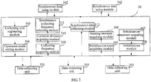
- FIG. 3 shows a structural block diagram of a data collecting apparatus according to Embodiment 3 of the present invention.
- the data collecting apparatus 30 may be applied in an apparatus including multiple data collecting units 301, for example, a fixed terminal such as a personal computer and a server, or a mobile terminal such as a notebook, a tablet, and a mobile phone, where generally the mobile terminal further includes multiple synchronous data using modules 302.
- the data collecting apparatus 30 may include: a collecting unit registering module 303, an operation mode setting module 304, an initialization time acquiring module 305, a starting moment acquiring module 306, an initialization moment acquiring module 307, an initialization module 308, a collecting frequency acquiring module 309, a common divisor acquiring module 310, a synchronous collecting frequency selecting module 311, and a synchronous data collecting module 312.
- the data collecting units 301 are configured to collect initial data according to a particular collecting frequency.
- the data collecting units 301 may be various sensors in the mobile terminal, and the collecting frequency herein may refer to an actual collecting frequency of a sensor or may refer to a frequency at which a sensor reports the initial data.
- the data collecting units 301 generally have two operation modes: a first operation mode in which whether a difference between data collected this time and data collected for the previous time is greater than a predetermined threshold is determined, where if the difference between the data collected this time and the data collected for the previous time is greater than the predetermined threshold, the data collected this time is reported as the initial data; and a second operation mode in which data collected each time is reported as the initial data.
- the data collecting units 301 run in the first operation mode.
- the synchronous data using modules 302 are configured to use or process data collected at a same moment by each data collecting unit 301, where the data collected at a same moment by each data collecting unit 301 is synchronous data.
- the synchronous data using modules 302 may be applications.
- the synchronous data is provided by the synchronous data collecting module 312.
- the collecting unit registering module 303 is configured to, when the synchronous data using modules 302 require the synchronous data, register all or a part of the data collecting units 301 as data collecting units 301 that are to collect synchronous data.
- a terminal may include multiple data collecting units 301, and the synchronous data using modules 302 may require precise data at a same moment of only a part of the data collecting units 301. Therefore, the synchronous data using modules 302 may register, by using the collecting unit registering module 303, all or a part of the data collecting units 301 as the data collecting units that are to collect synchronous data.
- the data collecting units that are to collect synchronous data are related data collecting units when the synchronous data using modules 302 need to acquire the synchronous data.
- the synchronous data using modules 302 may not register one or more other data collecting units in the terminal.
- the operation mode setting module 304 is configured to set an operation mode of each data collecting unit 301 registered by the collecting unit registering module 303 as the second operation mode from the default first operation mode.
- the second operation mode refers to an operation mode in which the data collecting units 301 report data collected each time as the initial data.
- the initialization time acquiring module 305 is configured to acquire initialization duration of at least two data collecting units 301 registered by the collecting unit registering module 303 and the maximum initialization duration in the initialization duration.
- the initialization duration refers to a period of time from which a sensor is powered on and starts to be initialized and to which the sensor completes initialization and performs data collecting for the first time. For different data collecting units 301, the initialization duration maybe different from each other.
- the starting moment acquiring module 306 is configured to acquire a collection starting moment, and the collection starting moment is not smaller than a moment obtained after the maximum initialization duration is prolonged backwards based on a current moment.
- the initialization moment acquiring module 307 is configured to collect initialization moments of the at least two data collecting units 301 registered by the collecting unit registering module 303.
- the initialization moments of the at least two data collecting units 301 registered by the collecting unit registering module 303 may be moments obtained after respective initialization duration of the data collecting units 301 is advanced based on the collection starting moment acquired by the starting moment acquiring module 306.
- the initialization module 308 is configured to initialize, according to the initialization moments acquired by the initialization moment acquiring module 307, the at least two data collecting units 301 registered by the collecting unit registering module 303. After simultaneously completing initialization processes at the collection starting moment acquired by the starting time acquiring module 306, the at least two data collecting units 301 registered by the collecting unit registering module 303 collect the initial data at their respective collecting frequencies.
- the collecting frequency acquiring module 309 is configured to acquire collecting frequencies of the at least two data collecting units 301 registered by the collecting unit registering module 303.
- the collecting frequencies are frequencies at which the data collecting units 301 collect the initial data in the second operation mode. It should be noted that each sensor may have more than one collecting frequency, and in this case all collecting frequencies of the sensor may be acquired.
- the collecting frequency herein may refer to an actual collecting frequency of the sensor or may refer to a frequency at which the sensor reports the initial data.
- the common divisor acquiring module 310 is configured to acquire all common divisors of values of the collecting frequencies, which are acquired by the collecting frequency acquiring module 309, of the at least two data collecting units 301.
- the synchronous collecting frequency selecting module 311 is configured to select one from all the common divisors acquired by the common divisor acquiring module 310 as a value of a synchronous collecting frequency.
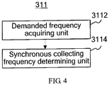
- the synchronous collecting frequency selecting module 311 may further specifically include, as shown in FIG. 4 , a demanded frequency acquiring unit 3112 and a synchronous collecting frequency determining unit 3114.
- the demanded frequency acquiring unit 3112 is configured to acquire a demanded frequency of the synchronous data, and the demanded frequency is a frequency required when the synchronous data using module 302 uses the synchronous data; and the synchronous collecting frequency determining unit 3114 is configured to select the minimum common divisor of a common divisor, which is in the common divisors acquired by the common divisor acquiring module 310 and is not smaller than a value of the demanded frequency acquired by the demanded frequency acquiring unit 3112, as the value of the synchronous collecting frequency.
- the demanded frequency acquiring unit 3112 may further specifically include a lowest frequency acquiring subunit and a demanded frequency selecting subunit (not shown specifically).
- the lowest frequency acquiring subunit is configured to acquire lowest frequencies required when synchronous data using modules 302 use the synchronous data.
- the demanded frequency selecting subunit is configured to select the least common multiple of values of the lowest frequencies acquired by the lowest frequency acquiring subunit as a value of the demanded frequency.
- the synchronous data collecting module 312 is configured to collect, according to the synchronous collecting frequency selected by the synchronous collecting frequency selecting unit 311, the initial data collected by each data collecting unit 301 so as to obtain the synchronous data.
- the data collecting apparatus may be a smartphone.
- the smartphone includes a gyroscope sensor, a gravitational acceleration sensor, an infrared sensor, and an electronic compass sensor. These four sensors may be four data collecting units 301.
- a racing game running in the smartphone may be a synchronous data using module 302. After a user triggers the racing game to run, this racing game may register, by using the collecting unit registering module 303, the gyroscope sensor and the gravitational acceleration sensor as at least two data collecting units 301 that are to collect synchronous data.
- the operation mode setting module 304 sets, from the default first operation mode, operation modes of the gyroscope sensor and the gravitational acceleration sensor as the second operation mode in which the data collected each time is reported as the initial data.
- the initialization time acquiring module 305 may acquire that initialization duration of the gyroscope sensor is 190 ms, and initialization duration of the gravitational acceleration sensor is 120 ms, of which the maximum initialization duration is 190 ms.
- the initialization module 308 starts a corresponding timer to enable the gyroscope sensor to perform the re-initialization at the moment indicated by (the current moment + 100 ms) and to enable the gravitational acceleration sensor to perform re-initialization at the moment indicated by (the current moment + 170 ms). Hence, both the gyroscope sensor and the gravitational acceleration sensor will simultaneously complete the initialization at the collection starting moment and start to collect the initial data at their respective frequencies.
- the collecting frequency acquiring module 309 may acquire that a collecting frequency of the gyroscope sensor is 100 HZ and a collecting frequency of the gravitational acceleration sensor is 200 HZ.
- Values of common divisor frequencies obtained by the common divisor acquiring module 310 may be 1, 2, 4, 5, 10, 20, 25, 50, and 100.
- the demanded frequency acquiring unit 3112 in the synchronous collecting frequency selecting module 311 acquires that the racing game needs to use the synchronous data at a lowest frequency of 25 HZ. Then, the synchronous collecting frequency determining unit 3114 in the synchronous collecting frequency selecting module 311 selects 25 HZ as the synchronous collecting frequency.
- the synchronous data collecting module 312 may collect, by using the synchronous collecting frequency, the initial data collected by the gyroscope sensor and the gravitational acceleration sensor so as to obtain the synchronous data. Finally, the racing game may use the synchronous data to calculate various parameters during the game.
- the operation mode setting module 302 may set the operation modes of the gyroscope sensor and the gravitational acceleration sensor as the originally default first operation mode from the second operation mode.
- multiple groups of synchronous data of each data collecting unit are obtained in a manner of adjusting collection starting moments of at least two data collecting units and at the same time capturing, according to a synchronous collecting frequency, synchronous data from initial data collected by the at least two data collecting units; and each group of synchronous data is accurate data of each data collecting unit at a same moment, so that an application using the multiple groups of synchronous data can avoid occurrence of an error.
- the program may be stored in a computer readable storage medium.
- the storage medium may include: a read-only memory, a magnetic disk, or an optical disc.
Landscapes
- Physics & Mathematics (AREA)
- General Physics & Mathematics (AREA)
- Engineering & Computer Science (AREA)
- Theoretical Computer Science (AREA)
- Databases & Information Systems (AREA)
- General Engineering & Computer Science (AREA)
- Data Mining & Analysis (AREA)
- Computing Systems (AREA)
- Computer Networks & Wireless Communication (AREA)
- Signal Processing (AREA)
- Telephone Function (AREA)
- Arrangements For Transmission Of Measured Signals (AREA)
- Telephonic Communication Services (AREA)
Claims (12)
- Datensammelverfahren, das in einer Vorrichtung angewendet wird, die mehrere Datensammeleinheiten umfasst, wobei das Verfahren Folgendes umfasst:gleichzeitiges Sammeln, durch mindestens zwei Datensammeleinheiten, von anfänglichen Daten bei ihren jeweiligen Sammelfrequenzen und zu einem Sammlungsstartzeitpunkt undSammeln, bei einer synchronen Sammelfrequenz, der anfänglichen Daten, die durch die mindestens zwei Datensammeleinheiten gesammelt werden, damit synchrone Daten erhalten werden, wobeidie synchrone Sammelfrequenz eine gemeinsame Teilerfrequenz der jeweiligen Sammelfrequenzen der mindestens zwei Datensammeleinheiten ist;wobei das Verfahren vor dem gleichzeitigen Sammeln, durch mindestens zwei Datensammeleinheiten, von anfänglichen Daten bei ihren jeweiligen Sammelfrequenzen und zu einem Sammlungsstartzeitpunkt ferner Folgendes umfasst:Erfassen der jeweiligen Initialisierungsdauern der mindestens zwei Datensammeleinheiten und der maximalen Initialisierungsdauer der mindestens zwei Initialisierungsdauern undSetzen des Sammlungsstartzeitpunkts, wobei der Sammlungsstartzeitpunkt ein erster Zeitpunkt ist, der einem gegenwärtigen Zeitpunkt plus die maximale Initialisierungsdauer oder einem Zeitpunkt nach dem ersten Zeitpunkt entspricht.
- Datensammelverfahren nach Anspruch 1, wobei das gleichzeitige Sammeln, durch mindestens zwei Datensammeleinheiten, von anfänglichen Daten bei ihren jeweiligen Sammelfrequenzen und zu einem Sammlungsstartzeitpunkt spezifisch Folgendes umfasst:Erfassen von Initialisierungszeitpunkten der mindestens zwei Datensammeleinheiten, wobei die Initialisierungszeitpunkte der mindestens zwei Datensammeleinheiten als der Sammlungsstartzeitpunkt minus die jeweilige Initialisierungsdauer, die der Datensammeleinheit entspricht, erfasst werden;Initialisieren der mindestens zwei Datensammeleinheiten zu den Initialisierungszeitpunkten und,nachdem gleichzeitig Initialisierungsprozesse zum Sammlungsstartzeitpunkt abgeschlossen werden, Sammeln, durch die mindestens zwei Datensammeleinheiten, der anfänglichen Daten bei ihren jeweiligen Sammelfrequenzen.
- Datensammelverfahren nach Anspruch 1 oder 2, wobei das Verfahren vor dem Sammeln, gemäß einer synchronen Sammelfrequenz, der anfänglichen Daten, die durch die mindestens zwei Datensammeleinheiten gesammelt werden, damit synchrone Daten erhalten werden, ferner Folgendes umfasst:Erfassen der Sammelfrequenzen der mindestens zwei Datensammeleinheiten;Erfassen aller gemeinsamer Teiler von Werten der Sammelfrequenzen der mindestens zwei Datensammeleinheiten undAuswählen eines Teilers aus allen gemeinsamen Teilern als einen Wert der synchronen Sammelfrequenz.
- Datensammelverfahren nach Anspruch 3, wobei das Auswählen eines Teilers aus allen gemeinsamen Teilern als einen Wert der synchronen Sammelfrequenz spezifisch Folgendes umfasst:Erfassen einer geforderten Frequenz der synchronen Daten, wobei die geforderte Frequenz eine Frequenz ist, die benötigt wird, wenn ein synchrone Daten verwendendes Modul die synchronen Daten verwendet; undVerwenden des minimalen gemeinsamen Teilers eines gemeinsamen Teilers in den gemeinsamen Teilern, der nicht kleiner als ein Wert der geforderten Frequenz ist, als den Wert der synchronen Sammelfrequenz.
- Datensammelverfahren nach Anspruch 4, wobei das Erfassen einer geforderten Frequenz der synchronen Daten spezifisch Folgendes umfasst:Erfassen von niedrigsten Frequenzen, die benötigt werden, wenn synchrone Daten verwendende Module die synchronen Daten verwenden; undVerwenden des kleinsten gemeinsamen Vielfachen von Werten aller niedrigsten Frequenzen als den Wert der geforderten Frequenz.
- Datensammelvorrichtung, die in einer Vorrichtung angewendet wird, die mehrere Datensammeleinheiten umfasst, wobei die Datensammelvorrichtung Folgendes umfasst: ein Synchrone-Daten-Sammelmodul, wobei:mindestens zwei Datensammeleinheiten in den mehreren Datensammeleinheiten ausgelegt sind zum gleichzeitigen Sammeln von anfänglichen Daten bei ihren jeweiligen Sammelfrequenzen und zu einem Sammlungsstartzeitpunkt; unddas Synchrone-Daten-Sammelmodul ausgelegt ist zum Sammeln, bei einer synchronen Sammelfrequenz, der anfänglichen Daten, die durch die mindestens zwei Datensammeleinheiten gesammelt werden, damit synchrone Daten erhalten werden, wobeidie synchrone Sammelfrequenz eine gemeinsame Teilerfrequenz der jeweiligen Sammelfrequenzen der mindestens zwei Datensammeleinheiten ist;wobei die Datensammelvorrichtung ferner Folgendes umfasst:
ein Initialisierungsdauer-Erfassungsmodul und ein Startzeitpunkt-Erfassungsmodul, wobei:das Initialisierungsdauer-Erfassungsmodul ausgelegt ist zum Erfassen der jeweiligen Initialisierungsdauern der mindestens zwei Datensammeleinheiten und der maximalen Initialisierungsdauer der mindestens zwei Initialisierungsdauern unddas Startzeitpunkt-Erfassungsmodul ausgelegt ist zum Setzen des Sammlungsstartzeitpunkts, wobei der Sammlungsstartzeitpunkt ein erster Zeitpunkt ist, der einem gegenwärtigen Zeitpunkt plus die maximale Initialisierungsdauer oder einem Zeitpunkt nach dem ersten Zeitpunkt entspricht. - Datensammelvorrichtung nach Anspruch 6, wobei die Datensammelvorrichtung ferner Folgendes umfasst:
ein Initialisierungszeitpunkt-Erfassungsmodul und ein Initialisierungsmodul, wobei:das Initialisierungszeitpunkt-Erfassungsmodul ausgelegt ist zum Erfassen der jeweiligen Initialisierungszeitpunkte der mindestens zwei Datensammeleinheiten, und die Initialisierungszeitpunkte der mindestens zwei Datensammeleinheiten als der Sammlungsstartzeitpunkt minus die jeweilige Initialisierungsdauer, die der Datensammeleinheit entspricht, erfasst werden;das Initialisierungsmodul ausgelegt ist zum Initialisieren der mindestens zwei Datensammeleinheiten zu den Initialisierungszeitpunkten; sodass die mindestens zwei Datensammeleinheiten anfängliche Daten bei ihren jeweiligen Sammelfrequenzen sammeln, nachdem Initialisierungsprozesse gleichzeitig zum Sammlungsstartzeitpunkt abgeschlossen werden. - Datensammelvorrichtung nach Anspruch 6 oder 7, wobei die Datensammelvorrichtung ferner Folgendes umfasst:
ein Sammelfrequenz-Erfassungsmodul, ein Gemeinsamer-Teiler-Erfassungsmodul und ein Synchrone-Sammelfrequenz-Auswahlmodul, wobei:das Sammelfrequenz-Erfassungsmodul ausgelegt ist zum Erfassen der Sammelfrequenzen der mindestens zwei Datensammeleinheiten;das Gemeinsamer-Teiler-Erfassungsmodul ausgelegt ist zum Erfassen aller gemeinsamer Teiler von Werten der Sammelfrequenzen der mindestens zwei Datensammeleinheiten unddas Synchrone-Sammelfrequenz-Auswahlmodul ausgelegt ist zum Auswählen eines Teilers aus allen gemeinsamen Teilern als einen Wert der synchronen Sammelfrequenz. - Datensammelvorrichtung nach Anspruch 8, wobei das Synchrone-Sammelfrequenz-Auswahlmodul Folgendes umfasst: eine Geforderte-Frequenz-Erfassungseinheit und eine Synchrone-Sammelfrequenz-Bestimmungseinheit, wobei:die Geforderte-Frequenz-Erfassungseinheit ausgelegt ist zum Erfassen einer geforderten Frequenz von synchronen Daten, wobei die geforderte Frequenz eine Frequenz ist, die benötigt wird, wenn ein synchrone Daten verwendendes Modul die synchronen Daten verwendet; unddie Synchrone-Sammelfrequenz-Bestimmungseinheit ausgelegt ist zum Verwenden des minimalen gemeinsamen Teilers eines gemeinsamen Teilers in den gemeinsamen Teilern, der nicht kleiner als ein Wert der geforderten Frequenz ist, als den Wert der synchronen Sammelfrequenz.
- Datensammelvorrichtung nach Anspruch 9, wobei die Geforderte-Frequenz-Erfassungseinheit Folgendes umfasst: eine Niedrigste-Frequenz-Erfassungsuntereinheit und eine Geforderte-Frequenz-Auswahluntereinheit, wobei:die Niedrigste-Frequenz-Erfassungsuntereinheit ausgelegt ist zum Erfassen von niedrigsten Frequenzen, die benötigt werden, wenn synchrone Daten verwendende Module die synchronen Daten verwenden; unddie Geforderte-Frequenz-Auswahluntereinheit ausgelegt ist zum Auswählen des kleinsten gemeinsamen Vielfachen von Werten aller niedrigsten Frequenzen als den Wert der geforderten Frequenz.
- Mobiles Endgerät, das Folgendes umfasst:mehrere Datensammeleinheiten, wobei mindestens zwei Datensammeleinheiten in den mehreren Datensammeleinheiten ausgelegt sind zum gleichzeitigen Sammeln von anfänglichen Daten bei ihren jeweiligen Sammelfrequenzen und zu einem Sammlungsstartzeitpunkt; undeine Datensammelvorrichtung nach einem der Ansprüche 6-10.
- Mobiles Endgerät, das Folgendes umfasst:mehrere Datensammeleinheiten undeinen oder mehrere Prozessoren, wobei:mindestens zwei Datensammeleinheiten in den mehreren Datensammeleinheiten ausgelegt sind zum gleichzeitigen Sammeln von anfänglichen Daten bei ihren jeweiligen Sammelfrequenzen und zu einem Sammlungsstartzeitpunkt undder eine oder die mehreren Prozessoren ausgelegt sind zum Durchführen des Verfahrens nach einem der Ansprüche 1-5.
Applications Claiming Priority (2)
| Application Number | Priority Date | Filing Date | Title |
|---|---|---|---|
| CN201210044164.5A CN102607645B (zh) | 2012-02-24 | 2012-02-24 | 数据采集方法及装置、移动终端 |
| PCT/CN2013/071630 WO2013123868A1 (zh) | 2012-02-24 | 2013-02-18 | 数据采集方法及装置、移动终端 |
Publications (3)
| Publication Number | Publication Date |
|---|---|
| EP2808656A1 EP2808656A1 (de) | 2014-12-03 |
| EP2808656A4 EP2808656A4 (de) | 2015-03-25 |
| EP2808656B1 true EP2808656B1 (de) | 2018-08-29 |
Family
ID=46525234
Family Applications (1)
| Application Number | Title | Priority Date | Filing Date |
|---|---|---|---|
| EP13752100.1A Active EP2808656B1 (de) | 2012-02-24 | 2013-02-18 | Datenerfassungsverfahren, vorrichtung und mobile endvorrichtung |
Country Status (6)
| Country | Link |
|---|---|
| US (1) | US9483543B2 (de) |
| EP (1) | EP2808656B1 (de) |
| JP (1) | JP5857374B2 (de) |
| KR (1) | KR101900870B1 (de) |
| CN (1) | CN102607645B (de) |
| WO (1) | WO2013123868A1 (de) |
Families Citing this family (18)
| Publication number | Priority date | Publication date | Assignee | Title |
|---|---|---|---|---|
| CN102607645B (zh) | 2012-02-24 | 2014-12-03 | 华为终端有限公司 | 数据采集方法及装置、移动终端 |
| CN103475918A (zh) * | 2013-09-04 | 2013-12-25 | 深圳市同洲电子股份有限公司 | 一种自动控制移动终端传感器的方法及装置 |
| CN103632055A (zh) * | 2013-11-29 | 2014-03-12 | 华为技术有限公司 | 数据采集方法和装置 |
| CN103970700A (zh) * | 2014-05-28 | 2014-08-06 | 四川效率源信息安全技术有限责任公司 | 一种可同时恢复并提取多部安卓设备数据的装置和方法 |
| US9672155B2 (en) | 2014-07-08 | 2017-06-06 | Stmicroelectronics S.R.L. | Method and device for storing data in a memory, corresponding apparatus and computer program product |
| CN104573134B (zh) * | 2014-12-19 | 2018-10-16 | 深圳怡化电脑股份有限公司 | 数据采集方法和数据采集设备 |
| CN105093985B (zh) * | 2015-07-22 | 2018-08-14 | 深圳多新哆技术有限责任公司 | 一种控制传感器上电方法 |
| ITUB20153254A1 (it) | 2015-08-27 | 2017-02-27 | St Microelectronics Srl | Metodo di salvataggio intelligente di dati ad elevata densita' e relativo dispositivo di memoria |
| CN106021008B (zh) * | 2016-05-23 | 2019-07-26 | 维沃移动通信有限公司 | 一种控制方法及终端 |
| JP6348163B2 (ja) | 2016-12-15 | 2018-06-27 | ファナック株式会社 | 制御装置及び制御システム |
| US11016957B2 (en) * | 2018-02-28 | 2021-05-25 | Microsoft Technology Licensing, Llc | Sensor data based query results |
| US20190331493A1 (en) * | 2018-04-25 | 2019-10-31 | Xsens Holding B.V. | Asynchronous SDI |
| JP2022535471A (ja) * | 2019-08-30 | 2022-08-09 | バイドゥドットコム タイムズ テクノロジー (ベイジン) カンパニー リミテッド | 自動運転車両用の同期センサ |
| CN110784377A (zh) * | 2019-10-30 | 2020-02-11 | 国云科技股份有限公司 | 一种多云环境下的云监控数据统一管理的方法 |
| CN110839221B (zh) * | 2019-11-04 | 2022-02-11 | 大连大学 | 节点数据传输方法 |
| CN113358120B (zh) * | 2021-06-04 | 2022-08-05 | 广东人工智能与先进计算研究院 | 一种传感器的采样方法以及相关装置 |
| CN113918652A (zh) * | 2021-10-19 | 2022-01-11 | 广州极飞科技股份有限公司 | 数据同步方法、装置及可读存储介质 |
| CN118469355B (zh) * | 2024-07-15 | 2024-09-27 | 上海海达通信有限公司 | 基于物联网的数字孪生智慧工业园区大数据能效管理系统 |
Family Cites Families (17)
| Publication number | Priority date | Publication date | Assignee | Title |
|---|---|---|---|---|
| JPH04223798A (ja) * | 1990-12-26 | 1992-08-13 | Seibu Gas Kk | 無線データ通信システム |
| US6693511B1 (en) * | 1999-09-24 | 2004-02-17 | Ge Interlogix, Inc. | System and method for communicating with dormant radio frequency identification tags |
| US7020701B1 (en) * | 1999-10-06 | 2006-03-28 | Sensoria Corporation | Method for collecting and processing data using internetworked wireless integrated network sensors (WINS) |
| US6807553B2 (en) * | 2001-04-23 | 2004-10-19 | Safenet B.V. | Digital true random number generator circuit |
| JP3846330B2 (ja) * | 2002-02-21 | 2006-11-15 | 富士電機システムズ株式会社 | 収集データの同期化方法及びデータ処理システム |
| WO2007060721A1 (ja) | 2005-11-24 | 2007-05-31 | Hewlett-Packard Development Company, L.P. | ネットワーク管理装置およびネットワークの管理方法 |
| CN1909499B (zh) * | 2006-08-16 | 2010-10-13 | 华为技术有限公司 | 一种多路数据采集装置及方法 |
| US8952832B2 (en) * | 2008-01-18 | 2015-02-10 | Invensense, Inc. | Interfacing application programs and motion sensors of a device |
| US7657333B2 (en) * | 2007-09-27 | 2010-02-02 | Rockwell Automation Technologies, Inc. | Adjustment of data collection rate based on anomaly detection |
| US9378751B2 (en) * | 2008-06-19 | 2016-06-28 | Broadcom Corporation | Method and system for digital gain processing in a hardware audio CODEC for audio transmission |
| CN101320337A (zh) * | 2008-07-16 | 2008-12-10 | 北京中星微电子有限公司 | 一种定时器及其实现方法 |
| JP5470106B2 (ja) * | 2010-03-11 | 2014-04-16 | 株式会社日立メディコ | 医用画像撮影装置 |
| CN102098153A (zh) * | 2011-01-26 | 2011-06-15 | 北京世源信通科技有限公司 | 数据采集系统自同步的实现方法及装置 |
| US8725462B2 (en) * | 2011-05-13 | 2014-05-13 | Fujitsu Limited | Data aggregation platform |
| CN102274028B (zh) * | 2011-05-30 | 2013-03-27 | 国家体育总局体育科学研究所 | 一种人体运动状态多参数同步综合采集方法 |
| US8948781B2 (en) * | 2011-10-21 | 2015-02-03 | Alohar Mobile Inc. | Controlling operational states of a location sensing system of a mobile device |
| CN102607645B (zh) * | 2012-02-24 | 2014-12-03 | 华为终端有限公司 | 数据采集方法及装置、移动终端 |
-
2012
- 2012-02-24 CN CN201210044164.5A patent/CN102607645B/zh active Active
-
2013
- 2013-02-18 JP JP2014557984A patent/JP5857374B2/ja active Active
- 2013-02-18 WO PCT/CN2013/071630 patent/WO2013123868A1/zh not_active Ceased
- 2013-02-18 EP EP13752100.1A patent/EP2808656B1/de active Active
- 2013-02-18 KR KR1020147026805A patent/KR101900870B1/ko active Active
-
2014
- 2014-08-21 US US14/464,936 patent/US9483543B2/en active Active
Non-Patent Citations (1)
| Title |
|---|
| None * |
Also Published As
| Publication number | Publication date |
|---|---|
| KR101900870B1 (ko) | 2018-09-20 |
| JP2015513730A (ja) | 2015-05-14 |
| EP2808656A1 (de) | 2014-12-03 |
| KR20140138213A (ko) | 2014-12-03 |
| WO2013123868A1 (zh) | 2013-08-29 |
| JP5857374B2 (ja) | 2016-02-10 |
| US9483543B2 (en) | 2016-11-01 |
| EP2808656A4 (de) | 2015-03-25 |
| CN102607645B (zh) | 2014-12-03 |
| US20140365434A1 (en) | 2014-12-11 |
| CN102607645A (zh) | 2012-07-25 |
Similar Documents
| Publication | Publication Date | Title |
|---|---|---|
| EP2808656B1 (de) | Datenerfassungsverfahren, vorrichtung und mobile endvorrichtung | |
| EP3346696B1 (de) | Bilderfassungsverfahren und elektronische vorrichtung | |
| EP3586220B1 (de) | Elektronische vorrichtung und steuerungsverfahren dafür | |
| EP3346694A1 (de) | Elektronisches gerät und zugehörige bildaufnahmemethode | |
| EP3287895B1 (de) | Elektronische vorrichtung zur zusammenstellung von grafikdaten und verfahren dafür | |
| US12587935B2 (en) | Terminal behavior triggering method and terminal | |
| EP3098703A2 (de) | Verfahren für ausgabebildschirm und elektronische vorrichtung mit unterstützung davon | |
| EP3869790A1 (de) | Elektronische vorrichtung und bildaufnahmeverfahren davon | |
| US20160364888A1 (en) | Image data processing method and electronic device supporting the same | |
| KR102373491B1 (ko) | 회전체의 회전 인식 방법 및 그 방법을 처리하는 전자 장치 | |
| US20180302231A1 (en) | Method for processing job information and electronic device supporting same | |
| KR20170138667A (ko) | 어플리케이션을 활성화하는 방법 및 이를 제공하는 전자 장치 | |
| EP3023969A2 (de) | Anzeige und verfahren und elektronische vorrichtung | |
| KR20170099259A (ko) | 운동 정보 제공 방법 및 이를 지원하는 전자 장치 | |
| EP3489906B1 (de) | Elektronische vorrichtung und verfahren zur steuerung des betriebs einer elektronischen vorrichtung | |
| KR20180010884A (ko) | 무인 이동체를 제어하는 전자 장치, 그 제어 방법 및 저장 매체 | |
| KR20170055213A (ko) | 비행이 가능한 전자 장치를 이용한 촬영 방법 및 장치 | |
| US9894527B2 (en) | Electronic device and control method | |
| KR20180107642A (ko) | 외부 객체의 움직임에 기반하여 이동 위치를 결정하는 방법 및 이를 구현한 전자 장치 | |
| US20190349562A1 (en) | Method for providing interface for acquiring image of subject, and electronic device | |
| KR20170098093A (ko) | 전자 장치 및 그의 동작 방법 | |
| CN111813280B (zh) | 显示界面的控制方法、装置、电子设备及可读存储介质 | |
| EP3393111B1 (de) | Verfahren zur verringerung des stromverbrauchs und elektronische vorrichtung | |
| KR20180025763A (ko) | 미라캐스트 제공 장치 및 방법 | |
| KR20180094361A (ko) | 전자 장치 및 그의 동작 방법 |
Legal Events
| Date | Code | Title | Description |
|---|---|---|---|
| PUAI | Public reference made under article 153(3) epc to a published international application that has entered the european phase |
Free format text: ORIGINAL CODE: 0009012 |
|
| 17P | Request for examination filed |
Effective date: 20140827 |
|
| AK | Designated contracting states |
Kind code of ref document: A1 Designated state(s): AL AT BE BG CH CY CZ DE DK EE ES FI FR GB GR HR HU IE IS IT LI LT LU LV MC MK MT NL NO PL PT RO RS SE SI SK SM TR |
|
| A4 | Supplementary search report drawn up and despatched |
Effective date: 20150220 |
|
| RIC1 | Information provided on ipc code assigned before grant |
Ipc: G01D 5/244 20060101ALI20150216BHEP Ipc: G01D 9/00 20060101ALI20150216BHEP Ipc: G01D 21/02 20060101AFI20150216BHEP Ipc: G06F 17/30 20060101ALI20150216BHEP |
|
| DAX | Request for extension of the european patent (deleted) | ||
| RAP1 | Party data changed (applicant data changed or rights of an application transferred) |
Owner name: HUAWEI DEVICE (DONGGUAN) CO., LTD. |
|
| GRAP | Despatch of communication of intention to grant a patent |
Free format text: ORIGINAL CODE: EPIDOSNIGR1 |
|
| STAA | Information on the status of an ep patent application or granted ep patent |
Free format text: STATUS: GRANT OF PATENT IS INTENDED |
|
| INTG | Intention to grant announced |
Effective date: 20180313 |
|
| GRAS | Grant fee paid |
Free format text: ORIGINAL CODE: EPIDOSNIGR3 |
|
| GRAA | (expected) grant |
Free format text: ORIGINAL CODE: 0009210 |
|
| STAA | Information on the status of an ep patent application or granted ep patent |
Free format text: STATUS: THE PATENT HAS BEEN GRANTED |
|
| AK | Designated contracting states |
Kind code of ref document: B1 Designated state(s): AL AT BE BG CH CY CZ DE DK EE ES FI FR GB GR HR HU IE IS IT LI LT LU LV MC MK MT NL NO PL PT RO RS SE SI SK SM TR |
|
| REG | Reference to a national code |
Ref country code: GB Ref legal event code: FG4D |
|
| REG | Reference to a national code |
Ref country code: CH Ref legal event code: EP |
|
| REG | Reference to a national code |
Ref country code: AT Ref legal event code: REF Ref document number: 1035665 Country of ref document: AT Kind code of ref document: T Effective date: 20180915 |
|
| REG | Reference to a national code |
Ref country code: IE Ref legal event code: FG4D |
|
| REG | Reference to a national code |
Ref country code: DE Ref legal event code: R096 Ref document number: 602013042774 Country of ref document: DE |
|
| REG | Reference to a national code |
Ref country code: NL Ref legal event code: MP Effective date: 20180829 |
|
| REG | Reference to a national code |
Ref country code: LT Ref legal event code: MG4D |
|
| PG25 | Lapsed in a contracting state [announced via postgrant information from national office to epo] |
Ref country code: BG Free format text: LAPSE BECAUSE OF FAILURE TO SUBMIT A TRANSLATION OF THE DESCRIPTION OR TO PAY THE FEE WITHIN THE PRESCRIBED TIME-LIMIT Effective date: 20181129 Ref country code: NL Free format text: LAPSE BECAUSE OF FAILURE TO SUBMIT A TRANSLATION OF THE DESCRIPTION OR TO PAY THE FEE WITHIN THE PRESCRIBED TIME-LIMIT Effective date: 20180829 Ref country code: RS Free format text: LAPSE BECAUSE OF FAILURE TO SUBMIT A TRANSLATION OF THE DESCRIPTION OR TO PAY THE FEE WITHIN THE PRESCRIBED TIME-LIMIT Effective date: 20180829 Ref country code: NO Free format text: LAPSE BECAUSE OF FAILURE TO SUBMIT A TRANSLATION OF THE DESCRIPTION OR TO PAY THE FEE WITHIN THE PRESCRIBED TIME-LIMIT Effective date: 20181129 Ref country code: IS Free format text: LAPSE BECAUSE OF FAILURE TO SUBMIT A TRANSLATION OF THE DESCRIPTION OR TO PAY THE FEE WITHIN THE PRESCRIBED TIME-LIMIT Effective date: 20181229 Ref country code: GR Free format text: LAPSE BECAUSE OF FAILURE TO SUBMIT A TRANSLATION OF THE DESCRIPTION OR TO PAY THE FEE WITHIN THE PRESCRIBED TIME-LIMIT Effective date: 20181130 Ref country code: LT Free format text: LAPSE BECAUSE OF FAILURE TO SUBMIT A TRANSLATION OF THE DESCRIPTION OR TO PAY THE FEE WITHIN THE PRESCRIBED TIME-LIMIT Effective date: 20180829 Ref country code: FI Free format text: LAPSE BECAUSE OF FAILURE TO SUBMIT A TRANSLATION OF THE DESCRIPTION OR TO PAY THE FEE WITHIN THE PRESCRIBED TIME-LIMIT Effective date: 20180829 Ref country code: SE Free format text: LAPSE BECAUSE OF FAILURE TO SUBMIT A TRANSLATION OF THE DESCRIPTION OR TO PAY THE FEE WITHIN THE PRESCRIBED TIME-LIMIT Effective date: 20180829 |
|
| REG | Reference to a national code |
Ref country code: AT Ref legal event code: MK05 Ref document number: 1035665 Country of ref document: AT Kind code of ref document: T Effective date: 20180829 |
|
| PG25 | Lapsed in a contracting state [announced via postgrant information from national office to epo] |
Ref country code: AL Free format text: LAPSE BECAUSE OF FAILURE TO SUBMIT A TRANSLATION OF THE DESCRIPTION OR TO PAY THE FEE WITHIN THE PRESCRIBED TIME-LIMIT Effective date: 20180829 Ref country code: LV Free format text: LAPSE BECAUSE OF FAILURE TO SUBMIT A TRANSLATION OF THE DESCRIPTION OR TO PAY THE FEE WITHIN THE PRESCRIBED TIME-LIMIT Effective date: 20180829 Ref country code: HR Free format text: LAPSE BECAUSE OF FAILURE TO SUBMIT A TRANSLATION OF THE DESCRIPTION OR TO PAY THE FEE WITHIN THE PRESCRIBED TIME-LIMIT Effective date: 20180829 |
|
| PG25 | Lapsed in a contracting state [announced via postgrant information from national office to epo] |
Ref country code: EE Free format text: LAPSE BECAUSE OF FAILURE TO SUBMIT A TRANSLATION OF THE DESCRIPTION OR TO PAY THE FEE WITHIN THE PRESCRIBED TIME-LIMIT Effective date: 20180829 Ref country code: PL Free format text: LAPSE BECAUSE OF FAILURE TO SUBMIT A TRANSLATION OF THE DESCRIPTION OR TO PAY THE FEE WITHIN THE PRESCRIBED TIME-LIMIT Effective date: 20180829 Ref country code: CZ Free format text: LAPSE BECAUSE OF FAILURE TO SUBMIT A TRANSLATION OF THE DESCRIPTION OR TO PAY THE FEE WITHIN THE PRESCRIBED TIME-LIMIT Effective date: 20180829 Ref country code: ES Free format text: LAPSE BECAUSE OF FAILURE TO SUBMIT A TRANSLATION OF THE DESCRIPTION OR TO PAY THE FEE WITHIN THE PRESCRIBED TIME-LIMIT Effective date: 20180829 Ref country code: IT Free format text: LAPSE BECAUSE OF FAILURE TO SUBMIT A TRANSLATION OF THE DESCRIPTION OR TO PAY THE FEE WITHIN THE PRESCRIBED TIME-LIMIT Effective date: 20180829 Ref country code: RO Free format text: LAPSE BECAUSE OF FAILURE TO SUBMIT A TRANSLATION OF THE DESCRIPTION OR TO PAY THE FEE WITHIN THE PRESCRIBED TIME-LIMIT Effective date: 20180829 Ref country code: AT Free format text: LAPSE BECAUSE OF FAILURE TO SUBMIT A TRANSLATION OF THE DESCRIPTION OR TO PAY THE FEE WITHIN THE PRESCRIBED TIME-LIMIT Effective date: 20180829 |
|
| PG25 | Lapsed in a contracting state [announced via postgrant information from national office to epo] |
Ref country code: SK Free format text: LAPSE BECAUSE OF FAILURE TO SUBMIT A TRANSLATION OF THE DESCRIPTION OR TO PAY THE FEE WITHIN THE PRESCRIBED TIME-LIMIT Effective date: 20180829 Ref country code: SM Free format text: LAPSE BECAUSE OF FAILURE TO SUBMIT A TRANSLATION OF THE DESCRIPTION OR TO PAY THE FEE WITHIN THE PRESCRIBED TIME-LIMIT Effective date: 20180829 Ref country code: DK Free format text: LAPSE BECAUSE OF FAILURE TO SUBMIT A TRANSLATION OF THE DESCRIPTION OR TO PAY THE FEE WITHIN THE PRESCRIBED TIME-LIMIT Effective date: 20180829 |
|
| REG | Reference to a national code |
Ref country code: DE Ref legal event code: R097 Ref document number: 602013042774 Country of ref document: DE |
|
| RAP2 | Party data changed (patent owner data changed or rights of a patent transferred) |
Owner name: HUAWEI DEVICE CO., LTD. |
|
| REG | Reference to a national code |
Ref country code: DE Ref legal event code: R081 Ref document number: 602013042774 Country of ref document: DE Owner name: HUAWEI DEVICE CO., LTD., DONGGUAN, CN Free format text: FORMER OWNER: HUAWEI DEVICE (DONGGUAN) CO., LTD., DONGGUAN, GUANGDONG, CN Ref country code: DE Ref legal event code: R081 Ref document number: 602013042774 Country of ref document: DE Owner name: HONOR DEVICE CO., LTD., SHENZHEN, CN Free format text: FORMER OWNER: HUAWEI DEVICE (DONGGUAN) CO., LTD., DONGGUAN, GUANGDONG, CN |
|
| PLBE | No opposition filed within time limit |
Free format text: ORIGINAL CODE: 0009261 |
|
| STAA | Information on the status of an ep patent application or granted ep patent |
Free format text: STATUS: NO OPPOSITION FILED WITHIN TIME LIMIT |
|
| 26N | No opposition filed |
Effective date: 20190531 |
|
| PG25 | Lapsed in a contracting state [announced via postgrant information from national office to epo] |
Ref country code: SI Free format text: LAPSE BECAUSE OF FAILURE TO SUBMIT A TRANSLATION OF THE DESCRIPTION OR TO PAY THE FEE WITHIN THE PRESCRIBED TIME-LIMIT Effective date: 20180829 |
|
| REG | Reference to a national code |
Ref country code: CH Ref legal event code: PL |
|
| PG25 | Lapsed in a contracting state [announced via postgrant information from national office to epo] |
Ref country code: LU Free format text: LAPSE BECAUSE OF NON-PAYMENT OF DUE FEES Effective date: 20190218 Ref country code: MC Free format text: LAPSE BECAUSE OF FAILURE TO SUBMIT A TRANSLATION OF THE DESCRIPTION OR TO PAY THE FEE WITHIN THE PRESCRIBED TIME-LIMIT Effective date: 20180829 |
|
| REG | Reference to a national code |
Ref country code: BE Ref legal event code: MM Effective date: 20190228 |
|
| REG | Reference to a national code |
Ref country code: IE Ref legal event code: MM4A |
|
| PG25 | Lapsed in a contracting state [announced via postgrant information from national office to epo] |
Ref country code: LI Free format text: LAPSE BECAUSE OF NON-PAYMENT OF DUE FEES Effective date: 20190228 Ref country code: CH Free format text: LAPSE BECAUSE OF NON-PAYMENT OF DUE FEES Effective date: 20190228 |
|
| PG25 | Lapsed in a contracting state [announced via postgrant information from national office to epo] |
Ref country code: IE Free format text: LAPSE BECAUSE OF NON-PAYMENT OF DUE FEES Effective date: 20190218 |
|
| PG25 | Lapsed in a contracting state [announced via postgrant information from national office to epo] |
Ref country code: BE Free format text: LAPSE BECAUSE OF NON-PAYMENT OF DUE FEES Effective date: 20190228 |
|
| PG25 | Lapsed in a contracting state [announced via postgrant information from national office to epo] |
Ref country code: TR Free format text: LAPSE BECAUSE OF FAILURE TO SUBMIT A TRANSLATION OF THE DESCRIPTION OR TO PAY THE FEE WITHIN THE PRESCRIBED TIME-LIMIT Effective date: 20180829 |
|
| PG25 | Lapsed in a contracting state [announced via postgrant information from national office to epo] |
Ref country code: PT Free format text: LAPSE BECAUSE OF FAILURE TO SUBMIT A TRANSLATION OF THE DESCRIPTION OR TO PAY THE FEE WITHIN THE PRESCRIBED TIME-LIMIT Effective date: 20181229 Ref country code: MT Free format text: LAPSE BECAUSE OF NON-PAYMENT OF DUE FEES Effective date: 20190218 |
|
| REG | Reference to a national code |
Ref country code: DE Ref legal event code: R081 Ref document number: 602013042774 Country of ref document: DE Owner name: HONOR DEVICE CO., LTD., SHENZHEN, CN Free format text: FORMER OWNER: HUAWEI DEVICE CO., LTD., DONGGUAN, GUANGDONG, CN |
|
| PG25 | Lapsed in a contracting state [announced via postgrant information from national office to epo] |
Ref country code: CY Free format text: LAPSE BECAUSE OF FAILURE TO SUBMIT A TRANSLATION OF THE DESCRIPTION OR TO PAY THE FEE WITHIN THE PRESCRIBED TIME-LIMIT Effective date: 20180829 |
|
| REG | Reference to a national code |
Ref country code: GB Ref legal event code: 732E Free format text: REGISTERED BETWEEN 20210624 AND 20210630 |
|
| PG25 | Lapsed in a contracting state [announced via postgrant information from national office to epo] |
Ref country code: HU Free format text: LAPSE BECAUSE OF FAILURE TO SUBMIT A TRANSLATION OF THE DESCRIPTION OR TO PAY THE FEE WITHIN THE PRESCRIBED TIME-LIMIT; INVALID AB INITIO Effective date: 20130218 |
|
| PG25 | Lapsed in a contracting state [announced via postgrant information from national office to epo] |
Ref country code: MK Free format text: LAPSE BECAUSE OF FAILURE TO SUBMIT A TRANSLATION OF THE DESCRIPTION OR TO PAY THE FEE WITHIN THE PRESCRIBED TIME-LIMIT Effective date: 20180829 |
|
| PGFP | Annual fee paid to national office [announced via postgrant information from national office to epo] |
Ref country code: FR Payment date: 20241231 Year of fee payment: 13 |
|
| PGFP | Annual fee paid to national office [announced via postgrant information from national office to epo] |
Ref country code: DE Payment date: 20241231 Year of fee payment: 13 |
|
| PGFP | Annual fee paid to national office [announced via postgrant information from national office to epo] |
Ref country code: GB Payment date: 20250102 Year of fee payment: 13 |