EP2808213A1 - Système de gestion de véhicule hybride, appareil de commande de véhicule hybride et procédé de commande de véhicule hybride - Google Patents
Système de gestion de véhicule hybride, appareil de commande de véhicule hybride et procédé de commande de véhicule hybride Download PDFInfo
- Publication number
- EP2808213A1 EP2808213A1 EP13741045.2A EP13741045A EP2808213A1 EP 2808213 A1 EP2808213 A1 EP 2808213A1 EP 13741045 A EP13741045 A EP 13741045A EP 2808213 A1 EP2808213 A1 EP 2808213A1
- Authority
- EP
- European Patent Office
- Prior art keywords
- engine
- vehicle
- area
- information
- engine start
- Prior art date
- Legal status (The legal status is an assumption and is not a legal conclusion. Google has not performed a legal analysis and makes no representation as to the accuracy of the status listed.)
- Granted
Links
- 238000000034 method Methods 0.000 title claims description 10
- 238000004891 communication Methods 0.000 claims description 10
- 230000004044 response Effects 0.000 claims description 8
- 238000001514 detection method Methods 0.000 claims description 3
- 230000005540 biological transmission Effects 0.000 description 23
- 239000000446 fuel Substances 0.000 description 13
- 230000007704 transition Effects 0.000 description 10
- 238000010586 diagram Methods 0.000 description 6
- 238000012546 transfer Methods 0.000 description 6
- 238000013459 approach Methods 0.000 description 5
- 230000006870 function Effects 0.000 description 4
- 230000008859 change Effects 0.000 description 2
- 238000002485 combustion reaction Methods 0.000 description 2
- 230000002401 inhibitory effect Effects 0.000 description 2
- 230000008569 process Effects 0.000 description 2
- HBBGRARXTFLTSG-UHFFFAOYSA-N Lithium ion Chemical compound [Li+] HBBGRARXTFLTSG-UHFFFAOYSA-N 0.000 description 1
- 239000000498 cooling water Substances 0.000 description 1
- 230000007423 decrease Effects 0.000 description 1
- 230000003247 decreasing effect Effects 0.000 description 1
- 230000001419 dependent effect Effects 0.000 description 1
- 239000002283 diesel fuel Substances 0.000 description 1
- 230000000694 effects Effects 0.000 description 1
- 230000005611 electricity Effects 0.000 description 1
- 229910052739 hydrogen Inorganic materials 0.000 description 1
- 239000001257 hydrogen Substances 0.000 description 1
- 238000010348 incorporation Methods 0.000 description 1
- 230000005764 inhibitory process Effects 0.000 description 1
- 238000002347 injection Methods 0.000 description 1
- 239000007924 injection Substances 0.000 description 1
- 229910001416 lithium ion Inorganic materials 0.000 description 1
- 230000007246 mechanism Effects 0.000 description 1
- 239000004570 mortar (masonry) Substances 0.000 description 1
- 238000010248 power generation Methods 0.000 description 1
- 230000009467 reduction Effects 0.000 description 1
- 230000008929 regeneration Effects 0.000 description 1
- 238000011069 regeneration method Methods 0.000 description 1
- 230000002441 reversible effect Effects 0.000 description 1
- 230000001360 synchronised effect Effects 0.000 description 1
- 230000001052 transient effect Effects 0.000 description 1
Images


Classifications
-
- B—PERFORMING OPERATIONS; TRANSPORTING
- B60—VEHICLES IN GENERAL
- B60W—CONJOINT CONTROL OF VEHICLE SUB-UNITS OF DIFFERENT TYPE OR DIFFERENT FUNCTION; CONTROL SYSTEMS SPECIALLY ADAPTED FOR HYBRID VEHICLES; ROAD VEHICLE DRIVE CONTROL SYSTEMS FOR PURPOSES NOT RELATED TO THE CONTROL OF A PARTICULAR SUB-UNIT
- B60W20/00—Control systems specially adapted for hybrid vehicles
- B60W20/10—Controlling the power contribution of each of the prime movers to meet required power demand
- B60W20/12—Controlling the power contribution of each of the prime movers to meet required power demand using control strategies taking into account route information
-
- G—PHYSICS
- G07—CHECKING-DEVICES
- G07C—TIME OR ATTENDANCE REGISTERS; REGISTERING OR INDICATING THE WORKING OF MACHINES; GENERATING RANDOM NUMBERS; VOTING OR LOTTERY APPARATUS; ARRANGEMENTS, SYSTEMS OR APPARATUS FOR CHECKING NOT PROVIDED FOR ELSEWHERE
- G07C5/00—Registering or indicating the working of vehicles
- G07C5/08—Registering or indicating performance data other than driving, working, idle, or waiting time, with or without registering driving, working, idle or waiting time
- G07C5/0841—Registering performance data
-
- F—MECHANICAL ENGINEERING; LIGHTING; HEATING; WEAPONS; BLASTING
- F02—COMBUSTION ENGINES; HOT-GAS OR COMBUSTION-PRODUCT ENGINE PLANTS
- F02D—CONTROLLING COMBUSTION ENGINES
- F02D29/00—Controlling engines, such controlling being peculiar to the devices driven thereby, the devices being other than parts or accessories essential to engine operation, e.g. controlling of engines by signals external thereto
- F02D29/02—Controlling engines, such controlling being peculiar to the devices driven thereby, the devices being other than parts or accessories essential to engine operation, e.g. controlling of engines by signals external thereto peculiar to engines driving vehicles; peculiar to engines driving variable pitch propellers
-
- B—PERFORMING OPERATIONS; TRANSPORTING
- B60—VEHICLES IN GENERAL
- B60K—ARRANGEMENT OR MOUNTING OF PROPULSION UNITS OR OF TRANSMISSIONS IN VEHICLES; ARRANGEMENT OR MOUNTING OF PLURAL DIVERSE PRIME-MOVERS IN VEHICLES; AUXILIARY DRIVES FOR VEHICLES; INSTRUMENTATION OR DASHBOARDS FOR VEHICLES; ARRANGEMENTS IN CONNECTION WITH COOLING, AIR INTAKE, GAS EXHAUST OR FUEL SUPPLY OF PROPULSION UNITS IN VEHICLES
- B60K6/00—Arrangement or mounting of plural diverse prime-movers for mutual or common propulsion, e.g. hybrid propulsion systems comprising electric motors and internal combustion engines ; Control systems therefor, i.e. systems controlling two or more prime movers, or controlling one of these prime movers and any of the transmission, drive or drive units Informative references: mechanical gearings with secondary electric drive F16H3/72; arrangements for handling mechanical energy structurally associated with the dynamo-electric machine H02K7/00; machines comprising structurally interrelated motor and generator parts H02K51/00; dynamo-electric machines not otherwise provided for in H02K see H02K99/00
- B60K6/20—Arrangement or mounting of plural diverse prime-movers for mutual or common propulsion, e.g. hybrid propulsion systems comprising electric motors and internal combustion engines ; Control systems therefor, i.e. systems controlling two or more prime movers, or controlling one of these prime movers and any of the transmission, drive or drive units Informative references: mechanical gearings with secondary electric drive F16H3/72; arrangements for handling mechanical energy structurally associated with the dynamo-electric machine H02K7/00; machines comprising structurally interrelated motor and generator parts H02K51/00; dynamo-electric machines not otherwise provided for in H02K see H02K99/00 the prime-movers consisting of electric motors and internal combustion engines, e.g. HEVs
- B60K6/42—Arrangement or mounting of plural diverse prime-movers for mutual or common propulsion, e.g. hybrid propulsion systems comprising electric motors and internal combustion engines ; Control systems therefor, i.e. systems controlling two or more prime movers, or controlling one of these prime movers and any of the transmission, drive or drive units Informative references: mechanical gearings with secondary electric drive F16H3/72; arrangements for handling mechanical energy structurally associated with the dynamo-electric machine H02K7/00; machines comprising structurally interrelated motor and generator parts H02K51/00; dynamo-electric machines not otherwise provided for in H02K see H02K99/00 the prime-movers consisting of electric motors and internal combustion engines, e.g. HEVs characterised by the architecture of the hybrid electric vehicle
- B60K6/48—Parallel type
- B60K2006/4825—Electric machine connected or connectable to gearbox input shaft
-
- B—PERFORMING OPERATIONS; TRANSPORTING
- B60—VEHICLES IN GENERAL
- B60W—CONJOINT CONTROL OF VEHICLE SUB-UNITS OF DIFFERENT TYPE OR DIFFERENT FUNCTION; CONTROL SYSTEMS SPECIALLY ADAPTED FOR HYBRID VEHICLES; ROAD VEHICLE DRIVE CONTROL SYSTEMS FOR PURPOSES NOT RELATED TO THE CONTROL OF A PARTICULAR SUB-UNIT
- B60W2552/00—Input parameters relating to infrastructure
- B60W2552/20—Road profile
-
- B—PERFORMING OPERATIONS; TRANSPORTING
- B60—VEHICLES IN GENERAL
- B60W—CONJOINT CONTROL OF VEHICLE SUB-UNITS OF DIFFERENT TYPE OR DIFFERENT FUNCTION; CONTROL SYSTEMS SPECIALLY ADAPTED FOR HYBRID VEHICLES; ROAD VEHICLE DRIVE CONTROL SYSTEMS FOR PURPOSES NOT RELATED TO THE CONTROL OF A PARTICULAR SUB-UNIT
- B60W2556/00—Input parameters relating to data
- B60W2556/45—External transmission of data to or from the vehicle
- B60W2556/50—External transmission of data to or from the vehicle for navigation systems
-
- B—PERFORMING OPERATIONS; TRANSPORTING
- B60—VEHICLES IN GENERAL
- B60W—CONJOINT CONTROL OF VEHICLE SUB-UNITS OF DIFFERENT TYPE OR DIFFERENT FUNCTION; CONTROL SYSTEMS SPECIALLY ADAPTED FOR HYBRID VEHICLES; ROAD VEHICLE DRIVE CONTROL SYSTEMS FOR PURPOSES NOT RELATED TO THE CONTROL OF A PARTICULAR SUB-UNIT
- B60W2556/00—Input parameters relating to data
- B60W2556/45—External transmission of data to or from the vehicle
- B60W2556/65—Data transmitted between vehicles
-
- Y—GENERAL TAGGING OF NEW TECHNOLOGICAL DEVELOPMENTS; GENERAL TAGGING OF CROSS-SECTIONAL TECHNOLOGIES SPANNING OVER SEVERAL SECTIONS OF THE IPC; TECHNICAL SUBJECTS COVERED BY FORMER USPC CROSS-REFERENCE ART COLLECTIONS [XRACs] AND DIGESTS
- Y02—TECHNOLOGIES OR APPLICATIONS FOR MITIGATION OR ADAPTATION AGAINST CLIMATE CHANGE
- Y02T—CLIMATE CHANGE MITIGATION TECHNOLOGIES RELATED TO TRANSPORTATION
- Y02T10/00—Road transport of goods or passengers
- Y02T10/10—Internal combustion engine [ICE] based vehicles
- Y02T10/40—Engine management systems
-
- Y—GENERAL TAGGING OF NEW TECHNOLOGICAL DEVELOPMENTS; GENERAL TAGGING OF CROSS-SECTIONAL TECHNOLOGIES SPANNING OVER SEVERAL SECTIONS OF THE IPC; TECHNICAL SUBJECTS COVERED BY FORMER USPC CROSS-REFERENCE ART COLLECTIONS [XRACs] AND DIGESTS
- Y02—TECHNOLOGIES OR APPLICATIONS FOR MITIGATION OR ADAPTATION AGAINST CLIMATE CHANGE
- Y02T—CLIMATE CHANGE MITIGATION TECHNOLOGIES RELATED TO TRANSPORTATION
- Y02T10/00—Road transport of goods or passengers
- Y02T10/60—Other road transportation technologies with climate change mitigation effect
- Y02T10/62—Hybrid vehicles
-
- Y—GENERAL TAGGING OF NEW TECHNOLOGICAL DEVELOPMENTS; GENERAL TAGGING OF CROSS-SECTIONAL TECHNOLOGIES SPANNING OVER SEVERAL SECTIONS OF THE IPC; TECHNICAL SUBJECTS COVERED BY FORMER USPC CROSS-REFERENCE ART COLLECTIONS [XRACs] AND DIGESTS
- Y10—TECHNICAL SUBJECTS COVERED BY FORMER USPC
- Y10S—TECHNICAL SUBJECTS COVERED BY FORMER USPC CROSS-REFERENCE ART COLLECTIONS [XRACs] AND DIGESTS
- Y10S903/00—Hybrid electric vehicles, HEVS
- Y10S903/902—Prime movers comprising electrical and internal combustion motors
- Y10S903/903—Prime movers comprising electrical and internal combustion motors having energy storing means, e.g. battery, capacitor
Definitions
- the present invention relates to a management system of a hybrid vehicle, a control method for the hybrid vehicle and a control system for the hybrid vehicle.
- a drive mode select unit is provided, and, when the requested driving force is equal to an engine stop determination value or less, an EV drive mode is selectively adopted, and the vehicle is driven only by the driving force of the motor.
- the vehicle is then driven in an HEV mode so as to be driven at least by the driving force of the engine.
- the engine stop control system further comprises a deceleration determining means for predicting / detecting the deceleration of the vehicle so that the drive mode select unit is configured, when switching to the EV mode from the HEV drive mode, to transition to the EV mode from the HEV mode after lapse of a delay time which is set in advance. Further, as the deceleration determined based on the deceleration determining means decreases, the delay time will be set shorter (see PATENT DOCUMENT1).
- Patent Document 1 Japanese Patent Application Publication No. 2009-234565
- the object the present invention resides in providing a management system for a hybrid vehicle, a control system for the hybrid vehicle, and a control method for the hybrid vehicle, wherein the number of engine startups are inhibited or suppressed and the fuel economy will be improved.
- the problem described above is solved by acquiring from a plurality of vehicles engine operating information with respect to a travelling or moving distance or an engine operating time from the start of to the stop of an engine during the operation of a motor/generator and an engine operating position indicative of the point at which the engine is operating, and by identifying an engine start-up suppressing area for suppressing the engine start-up on map data based on the engine operating information.
- the positions at which the engine is easily and unnecessarily operated such as where the moving distance of vehicle with the engine running or operating is short or the engine operating time is short, etc., are identified and the engine start will be suppressed at these positions. Consequently, the number of engine start will be suppressed and the fuel economy will be improved.
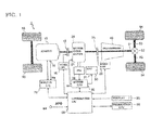
- the hybrid vehicle 1 of the embodiment according to the present invention is a vehicle of parallel system using a plurality of power sources for propulsion of the vehicle. As shown in FIG. 1 . the hybrid vehicle 1 is provided with an internal combustion engine 10 (hereinafter referred to as "engine"), first clutch 15, motor/generator 20 (motor and generator), second clutch 25, battery 30, inverter 35, automatic transmission 40, propeller shaft 51, differential gear unit 52, drive shaft 53, left and right driving wheels 54 and a display 90.
- engine internal combustion engine 10
- first clutch 15 motor/generator 20 (motor and generator)
- second clutch 25 battery 30
- inverter 35 automatic transmission 40
- propeller shaft 51 differential gear unit 52
- differential gear unit 52 drive shaft 53
- left and right driving wheels 54 and a display 90.
- a display 90 a display 90.
- CVT continuously variable transmission
- the engine 10 is an internal combustion engine driven by gasoline or diesel fuel, etc., and a valve openness of throttle valve, fuel injection amount, ignition timing, etc. are under control based on a control signal from the engine control module or unit 70.
- the first clutch 15 is interposed between the output shaft of the engine 10 and the rotating shaft of the motor/generator 20, and is thus selectively connected and disconnected for torque transmission between the engine 10 and the motor/generator 20.
- a multiple-plate wet clutch may be enumerated for continuously controlling a hydraulic flow rate and a hydraulic pressure by way of a linear solenoid.
- the first clutch 15 is controlled based on the control signal from unified or integrated control unit 60, and the clutch plates will be engaged (including engagement under a slipped state) or released.
- a motor generator 20 is a synchronous motor generator in which a permanent magnet is embedded in a rotor and a stator coil is wound around a stator.
- the motor-generator 20 is provided with a motor rotation speed sensor 21 to detect a rotor rotation speed Nm.
- This motor/generator 20 functions not only as an electric motor but also as a generator.
- the motor/generator 20 is driven to rotate (drive mode).
- the motor/generator 20 produces AC power by causing an electromotive force at both ends of the stator coils (regeneration).
- the AC power generated by the motor generator 20 is charged to the battery 30 after being converted to a direct current by the inverter 35.
- Examples of battery 30 are lithium ion secondary battery or nickel-hydrogen secondary battery.
- a current/voltage sensor 31 is attached to the battery 30 and these detection outputs are output to the motor control unit 80.
- the automatic transmission 40 has a multiple-step transmission with speed ratios such as seven forward and one reverse speed ratios, which are subject to switch or change automatically depending on vehicle speed, accelerator pedal opening, etc. This automatic transmission 40 may change speed ratios in accordance with control signal from the unified control unit 60.
- the output shaft of automatic transmission 40 is coupled to left and right drive wheels 54 via differential gear unit 52, left and right drive shafts 53. Note that reference “55” denotes steered front wheels.
- the telematics control unit 501 is provided with a communication device for transmitting and receiving with the external and communicates with a server described below. Further, the telematics control unit 50 is connected via a CAN communication with the integrated control unit 60.
- a display 90 is configured to provide a display device for displaying information or the like which is managed by the navigation system in the integrated control unit 60 for notifying the occupant information.
- the first drive mode is an electric motor drive mode (hereinafter called "EV mode”), which is achieved by releasing the first clutch 15 and engaging second clutch 25 such that vehicle is propelled by the motor/generator 20 as the only power source for driving the vehicle.
- EV mode electric motor drive mode
- the second drive mode is an engine-employing drive mode (hereinafter called "HEV mode”), which is achieved by engaging both the first clutch 15 and second clutch 25 such that the vehicle travels by engine 10 in addition to motor/generator 20 as the power source
- HEV mode engine-employing drive mode
- the third drive mode pertains to a slip drive mode (hereinafter called "WSC drive mode") which is achieved by maintaining second clutch 25 in a slipped state and vehicle is propelled by at least one of engine 1 and motor/generator 20 as the power source.
- WSC drive mode is in place to achieve a creep travel especially when the SOC (the amount of charge, State of Charge) is low at a low temperature of engine cooling water and the like.
- the HEV mode further includes three drive modes such as an "engine drive mode”, a “motor assist drive mode”, and a “power generating travel mode.
- the engine 10 serves as the sole power source for propelling the drive wheels 54.
- both the engine 10 and the motor/generator 20 serve as power sources for propelling the drive wheels 54.
- the engine 10 drives the drive wheels 54 while the motor/generator 20 functions as an electric generator
- a power generation mode may be eventually available in a vehicle stopped state where the motor/generator 20 is allowed to function as a generator by making use of the power of engine 10 to charge battery 30 or supplying power to an electric equipment.
- the control system of the hybrid vehicle 1 in the present embodiment is provided with a unified control unit 60, an engine control module or unit 70, and a motor control unit 80 as shown in FIG. 1 .
- These control units 60, 70, 80 are interconnected to each other through a CAN communication line, for example
- the engine control unit 70 outputs, in accordance with a target engine torque command tTe from the unified or integrated control unit 60, a command controlling an engine operation point (engine rotation speed Ne, engine torque Te) to a throttle valve actuator, injector, spark plug and the like provided with engine 10.
- a command controlling an engine operation point engine rotation speed Ne, engine torque Te
- the information about engine rotation speed Ne, engine torque Te is supplied to the integrated control unit 60 through the CAN communication line.
- the motor control unit 80 is configured to receive information from the motor rotation sensor 21 equipped on motor/generator 20, and, in accordance with command such as a target mortar/generator torque tTm, outputs a command controlling the operation point of motor/generator 20 (motor rotation speed Nm, motor torque Tm) to inverter 35.
- the motor control unit 80 is configured to calculate and manage the state of charge (SOC) of the battery 30 based on the current value and voltage detected by the current/voltage sensor 31. This battery SOC information is used for control information of the motor/generator 20, and sent to unified or integrated control unit 60 via CAN communication line.
- SOC state of charge
- the unified or integrated control unit 60 bears the function of driving or operating the hybrid vehicle 1 efficiently by controlling the operation point of the power train consisting the engine 10, the motor/generator 20, the automatic transmission 40, the first clutch 15, and the second clutch 25.
- the integrated control unit 60 calculates the operation point of the power train based on the information from each sensor acquired through CAN communication, and executes to control the operation of the engine by the control command to the engine control unit 70, the operation of the motor/generator 20 by the control command to the motor control unit 80, the operation of the automatic transmission 40 through the control command to the automatic transmission 40, the engagement/release operation of the first clutch 15 by the control command to the hydraulic unit 16 of the first clutch 15, and the engagement/release operation of the second clutch 25 by the control command to the hydraulic unit 26 of the second clutch 25.
- FIG. 2 represents a control block diagram of integrated control unit 60.
- the integrated control unit 60 includes, as shown in FIG. 2 , a target drive force computing section 61, a mode selecting section 62, a target charge/discharge computing unit 63, an operation point command section and a shift control section 65.
- the target drive force computing section 61 is configured to use the target driving force or torque map to compute a target driving force tFo0 based on the accelerator pedal opening APO detected by an accelerator opening sensor 69 and a transmission output rotation speed No (i.e., vehicle speed VSP) detected by the output rotation sensor 42 of the automatic transmission 40.
- a target driving force map is shown in FIG. 3
- the mode select unit 62 selects a target mode.
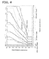
- FIG. 4 shows an example of the mode map.
- the mode map (shift map) in FIG. 4 depending on the vehicle speed VSP and accelerator opening APO, the regions for an EV drive mode, WSC drive mode and HEV drive mode are defined, respectively.
- the mode select unit 62 requires starting the engine 10 toward the operation point command section 64.
- the EV mode is assigned to the inside of the engine start line Lh while the HEV drive mode is assigned to the outside of the engine start line Lh.
- the engine start line Lo or Lh represents a threshold value for starting the engine 10. When the vehicle speed VSP and accelerator opening APO are greater than the threshold, the engine 10 is started.
- the engine start line Lo is a reference start line, and during the normal running or drive, the mode select unit 62 set the engine start line to Lo and selects the drive mode.
- the threshold value to start the engine 10 will be set by changing the position of the engine start line on the mode map shown in FIG. 4 .
- the control of the engine start line by the integrated control unit 60 will be described below.
- the WSC drive mode described above is assigned respectively to the low-speed region in both the EV drive mode and the HEV drive mode (region at 15 km/h or less, for example).
- the predetermined vehicle speed VSP1 that defines the WSC drive mode is configured to ensure the vehicle engine 10 to rotate autonomously or sustainably. Therefore, in the region lower than the predetermined vehicle speed VSP1, it is not possible to rotate engine 10 autonomously with the second clutch 25 being engaged.
- the target charge/discharge computing unit 63 computes a target charge/discharge power tP based on SOC of battery 30 by using a previously defined target charge/discharge amount map.
- the operation point command section 64 calculates, based on the accelerator pedal opening (APO), the target driving force tFo 0 , the target mode, the vehicle speed VSP, the target charge/discharge power tP, as a target operation point of the power train, a transient target engine torque tTe, a target motor/generator torque tTm (target motor/torque generator torque tNM may also be used), a target first clutch transmission toque capacity tTc 1 , a target second clutch transmission torque capacity tTc2, and a target speed ratio of automatic transmission 40.
- APO accelerator pedal opening
- APO accelerator pedal opening
- the target driving force tFo 0 the target mode
- the vehicle speed VSP the target charge/discharge power tP
- a target operation point of the power train a transient target engine torque tTe
- a target motor/generator torque tTm target motor/torque generator torque tNM may also be used
- the target engine torque tTe is sent to the engine control unit 70 from the integrated control unit 60, and the target motor generator torque tTm (or the target/motor generator rotation speed tNm) is sent to the motor control unit 80 from the integrated control unit 60.
- the operation point command unit or section 64 calculates both target first clutch torque transfer capacity tTc 1 and the second clutch torque transfer capacity tTc 2 under the target mode set by the mode select unit 62, in order to generate the target driving force.
- integrated control unit 60 sends solenoid current to each of the hydraulic unit 16 and 26, corresponding to the target first clutch torque transfer capacity tTc 1 and target second clutch torque transfer capacity tTc 2 , respectively.
- operation point command section 64 may allow engine 10 to start as a request on the system, regardless of the selected mode by mode select unit 62, when SOC (charge amount: State of Charge) is decreased and the like. For example, even if the mode select unit 62 selects EV mode, when the SOC of battery is low and the target charge/discharge computing unit 63 computing a target charge power to charge battery 30, then operation point command section 64 calculates a target calculation torque to start up engine 10 via engine control module 70.
- SOC charge amount: State of Charge
- the shift control unit 65 drives and controls a solenoid valve in the automatic transmission 40 so as to achieve the target shift stage along a shift schedule shown in a shift map.
- the shift map used at this time is such that the target gear position is set in advance based on the accelerator opening APO and the vehicle speed VSP as shown in FIG. 4 .
- FIG. 5 shows a block diagram of the hybrid vehicle 1, a plurality of vehicles 200, and the server.
- the server communicates with both the hybrid vehicle and the other, plural vehicles 200 and acquires the vehicle information of each vehicle.
- the server 100 is provided with database 101 and a server controller 102.
- the database 101 sores the information of each vehicle received by the server 100.
- the server 100 may communicate with the other information providing agencies such as JMA by wired or wireless transmission, the database 101 stores the information from that information providing agency such as the weather information including pressure or temperature.
- the administrator of the server 100 may update the data stored in the database 101 (such as map data, for example).
- the server controller 102 represents a controller for controlling the entire server 100 and includes an engine operating information acquisition unit 103 and an area specifying unit 104.
- the server controller 102 acquires or obtains the information transmitted from the vehicle and the vehicles 200 and analyzes the information to store in the database 101. Further, responsive to the requests of each vehicle 1, 200, the information stored in the database 101 will be broadcast to each vehicle 1, 200.
- the engine operating information acquisition unit 103 acquires the engine operating information transmitted from the vehicle 1 and the vehicle 200.
- the area specifying unit 104 specifies on the map data an engine start-up suppressing area to prevent the starting of the engine on the basis of the engine operating information obtained by the engine operating information acquisition unit 103. Similar to the hybrid vehicle 1, the vehicles 200 are also a hybrid vehicle.
- the engine operating information is described together with the control of the vehicle 1.
- the vehicle 1 repeats the start and stop of the engine 10 through the transitions between the EV mode and the HEV mode in response to the accelerator opening and the vehicle speed.
- the engine 10 is started. That is, during running, the vehicle 1, 200 are repeated to start the engine 30 at various positions in the map data.
- the accelerator opening may be increased in response to the driver's depression on the accelerator pedal to increase the driving force to start the engine 30.
- the period during which the engine 30 is running is shortened so that the mode reverts back to the original EV mode in a short period of time. That is, in the hybrid vehicle, in the specific road conditions, even if traveling in EV mode is possible, depending on the accelerator operation of the driver, the engine will be started and the mode may transition to the HEV mode. Further, such a start of the engine is likely to occur in the specific road conditions with respect to many hybrid vehicles.
- the areas are identified by the server 100 where many vehicle perform the engine start for a short period of time (or for a short distance). Further, in order to identify these areas, the vehicle 1, 200 transmit the engine operating information to the server 100.
- the engine operating information is such information for identifying by the server 100 the engine start-up suppressing area, and is transmitted from each vehicle 1, 200 to the server 100.
- the engine operating information contains an operating position indicative of the point at which the engine operates during the operation of the motor/generator 20, the moving distance of the vehicle 1 during the engine operation, and the accelerator pedal opening at the startup of the engine 10.
- the information in the engine operating position contains the position at the startup of the engine 10 and the position during the engine operating after the engine start-up. This position or location information is displayed in the coordinates of map data.
- the information on the operating position of the engine 10 is used to manage, in the map data, the position where the engine 30 of each vehicle 1,200 is started.
- the information of the moving distance of the vehicle 1, 200 during the operation of the engine 10 corresponds to the distance the vehicle 1, 200 has travelled.
- the information of the moving distance is used for the server 100 to determine whether or not the start of the engine 10 has been performed, depending on the specific conditions, in a short distance.
- the accelerator opening at the time of starting the engine 10 is used for the server 100 to determine whether the starting of the engine 10 is performed by an accelerator operation by the driver or performed in response to the system requirements. That is, while the accelerator opening degree is low, when the engine 10 is started, since the possibility that the engine 10 is operated in response to the system requirements is high, the server 100 uses the accelerator pedal opening to identify such engine start-ups.
- the integrated control unit 60 acquires, when the vehicle 1 transitions between the EV mode and the HEV mode, the information of these and stores in a memory not shown.
- the integrated controller 60 acquires the accelerator opening at the time of engine start-up as well as the vehicle position.
- the accelerator opening is obtained from a detection value of the accelerator opening sensor 69. Since the navigation system contained in the integrated control unit 60 grasps the current position of the vehicle, the vehicle position at the time of drive mode transition may be retrieved from the information that is managed by the navigation system 66.
- the integrated controller 60 when a transition is made to the EV mode from the HEV mode, obtains the accelerator opening and the vehicle position at the time of engine stop. Further, based on the position of the vehicle 1 at the time of engine start-up and the position of the vehicle 1 at the time of engine stop, the integrated controller 60 may grasps the moving distance of the vehicle 1 during the operation of the engine 1.
- the integrated controller 60 stores in memory the engine operating information obtained during the travel of the vehicle 1.
- the integrated control unit 60 transmits the engine operating information stored in the memory to the server 100 when a main switch (not shown) of the vehicle has been turned on or the main switch has been turned off.
- the engine operating information is similarly acquired and the engine operating information is transmitted to the server 100.
- the server 100 acquires the engine operating information of a plurality of vehicles 1, 200.
- the engine start-up suppressing area denotes an area the engine 10 is unnecessarily started, depending on the road conditions, by an increased amount of the accelerator pedal of the driver with a large accelerator opening.
- the server 100 identifies the engine control area and transmits the area information to each vehicle 1, 200.
- the server controller 102 acquires the engine operating information from each vehicle 1, 200 by the engine operating information acquisition unit 103, and stores the engine operating information in the data base in correspondence with the map data managed by the database.
- the server controller 102 determines, based on the accelerator opening contained in the engine operating information whether the start of the engine 10 indicated by the engine operating information is due to that caused by the system requirement or a driving request associated with the accelerator operation of the driver.
- the threshold value of the accelerator pedal opening is set in advance, according to which the determination is made on whether or not the start involved is system initiated or necessitated.
- the server controller 102 determines that the startup of the engine has been the engine start due to the request for drive as indicated by the engine operating information. On the other hand, the server controller 102 determines, when the accelerator opening is less than the accelerator opening threshold, that the start of the engine as indicated by the engine operating information is due to the engine start-up due to the system request. In the case of the engine start-up due to the system request, the server controller 102 does not store the obtained engine operating information in the database 101.
- the server controller 102 determines, based on the moving distance during the engine operation, whether or not the start of the engine 10 indicated by the engine operating information unnecessary for running the vehicle. Note that the engine start-up that is not necessary for running or travel of the vehicle 1 corresponds to the condition in which the EV mode may be maintained as the running or travel condition without the engine being started.
- the server controller 102 is provided in advance with a threshold distance to determine whether or not the unnecessary engine start-up is involved. Thus, when the moving distance during the engine operation is shorter than the threshold distance, the server controller 102 determines that the start of the engine 10 indicated by the engine operating information is that unnecessary for the travel of the vehicle because of a short engine operation and thus unnecessary engine operation. On the other hand, when the moving distance during the engine operation is longer than the threshold distance, the server controller 102 determines for the engine start that is necessary for travel of the vehicle 1. In the case of the engine start required for the running of the vehicle, the server controller 102 will not store in the database 101 the engine operating information obtained.
- the server controller 102 identifies the engine start that is necessitated by the request for driving force and thus not necessary for the running or travel of the vehicle, and plots the engine operating information to the operating position of the engine 10 contained in the engine operating information in the map data of the database 101.
- FIG. 6 shows the map data stored in the database 101 and the engine operating information to be plotted on the map data.
- a frame which is surrounded by latitude and meridian shows a mesh
- a white circle represents an engine operating information.
- the server controller 102 In order to manage the number of engine operating information in each area on the map data, the server controller 102 employs meshes as shown in FIG 6 .
- the mesh is obtained by dividing equally a predetermined area defined by a meridian constant. The size of the mesh is determined in advance.
- the server controller 102 plots the engine operating information by a point at a position in the mesh corresponding to the position of the engine operating information that has been identified through the determination described above. The plot is made with respect to the position of the engine start out of the positions during the engine operating information.
- the server controller 102 performs the similar determination and plotting of the information with respect to plural vehicles 200. Thus, a great deal of the engine operating information will be plotted in the map data of the database 101. Further, the server controller 012 deletes the engine operating information with respect to which a predetermined time has elapsed. Thus, the information being plotted on the map data represents the information that is frequently updated and plotted within a predetermined time period.
- the server controller 102 manages by the area identifying unit 104 the number of the engine operating information for each mesh on the map data to be stored on the database 101. For example, in the mesh A shown in FIG. 6 , six pieces of engine operating information are plotted, in the mesh B, seven pieces of engine operating information are plotted, in the mesh C, a single piece of engine operating information is plotted, and in the mesh D, two pieces of the engine operating information are plotted. In other words, in the mesh A, the total of six vehicles starts the engine with a constant period.
- the area identifying unit 104 compares the number of engine operating information of each mesh with an area specific threshold.
- the area specific threshold is a preset threshold set to specify that a plurality of vehicles have performed an unnecessary engine start on a road travelled in the mesh. Further, the area identifying unit 104 identifies a mesh as the engine start-up suppressing area when the number of engine operating information within the mesh exceeds the area specific threshold. For example, if the area specific threshold value is set to five, the meshes A and B are specified or identified as the engine start-up suppressing area whereas the meshes C and D will not be identified as the engine start-up suppressing area.
- the engine startups are performed in a short time period due to the request for driving force by the driver in many vehicles. Since this engine start-up is considered as an unnecessary engine startup for running or travelling the roads in the meshes A, and B, the meshes A, B are identified as the engine start-up suppressing area.
- the server controller 102 transmits the information containing the engine start-up suppressing areas in response to a request from the vehicle 1.
- the integrated control unit 60 communicates through the Telematics control unit 50 with the server 100, and transmits to the server 100 a signal indicating to acquire the engine start-up suppressing area information.
- the integrated control unit 60 After acquiring the engine start-up suppressing area information, the integrated control unit 60 stores that information in a memory (not shown). The integrated control unit 60 determines whether the engine start-p suppressing area is included in the travelled road extension of the vehicle 1, the vehicle is approaching the engine start-p suppressing area, and the vehicle 1 is travelling in the engine start-up suppressing area. For the purpose of this determination, the integrated control unit 60 measures a distance between the current position of the vehicle 1 managed by the navigation system 66 and the position of entry into the engine start-up suppressing area ahead of the travelling road (which corresponds to the crossing point of the travelling road and the mesh boundary corresponding to the area). Further, the integrated control unit 60 compares the measured distance to the threshold distance set in advance. When the measured distance is shorter than the threshold distance previously set, it is determined that the vehicle is close to the engine start-up suppressing areas.
- the integrated control unit 60 informs the occupant that the vehicle has approached the engine startup suppressing area by displaying the engine start-up suppressing areas on the map data.
- the integrated control unit 60 causes the mode select unit 62 to set the engine start line on the map shown in FIG. 4 to the engine start line Lh that is higher than the reference engine start line Lo so that the threshold to start the engine will be higher than the reference value.
- the engine start line Lh is drawn to a position higher than the engine start line Lo. Therefore, when the engine start line is set to Lh, as compared with the case where the engine start line is set to Lo, the region of EV drive mode is widened while the area of the HEV drive mode is narrower. That is, when set to the engine start line Lh, the vehicle speed or the accelerator position or opening for starting the engine 10 will be higher compared with the case where set to Lo so that the engine start will be suppressed or inhibited.
- the integrated control unit 60 causes the mode select unit 62 to set the engine start line on the map shown in FIG. 4 to the engine start line Lh that is higher than the reference engine start line Lo.
- the engine start line is maintained to adopt the engine start line Lh so that the engine start will be suppressed or inhibited.
- the control of the engine start line based on the engine start suppressing area in the present embodiment will be described. It is assumed that the vehicle 1 travels from the road in the mesh C to the road in the mesh A. While the vehicle 1 is travelling the road in the mesh C, since the area in the mesh C does not correspond to the engine startup suppressing area, the engine start line is set to the reference start line Lo.
- the integrated control unit 60 identifies that the vehicle 1 approaches the engine start suppressing area and causes the mode select unit 62 to the engine start line to Lh. Further, even if the driver of the vehicle 1 depresses the accelerator pedal during the travel on the road in the mesh C while viewing the road condition in the mesh C, the engine 10 will not be started since the engine start line has been set to the higher start line Lh. Thus, the engine 10 does not start and the vehicle 1 maintains the EV drive mode to pass the road in the mesh C. Thus, the engine start of the vehicle 1 will be suppressed in the engine start suppressing area. Then, when the vehicle 1 leaves the area of the mesh A, the mode select unit 62 returns the engine start line to the start line Lo.
- FIG. 7 shows the control procedure of the vehicles 1, 200 and a flowchart of the control procedure of the server 100.
- the controls represented by steps S104 to S106 are repeatedly carried out at a predetermined cycle.
- step S101 the integrated control unit 60 of the vehicle 1 transmits the engine operating information to the server 100. Also, in step S301, the integrated control unit 60 of the vehicle 200 transmits the engine the engine operating information to the server 100.
- step S201 the server controller 102 determines whether or not the engine operating information acquisition unit 103 has received the engine operating information from the vehicles 1, 200. When not received, control proceeds to step S205.
- the server controller 102 uses the accelerator opening contained in the acquired engine operating information in step S202 to determine whether or not the engine start is due to a request for driving force.
- the accelerator opening is less than the accelerator opening threshold value, the server controller 102 determines not to be the engine start due to the request for driving force, and control proceeds to step S205.
- the server controller 102 determines for the engine start necessitated by the driving request and control proceeds to step S203.
- step S203 based on the information of the position at the start of the engine and at the time of operation stop contained in the acquired engine operating information, the server controller 102 measures the moving distance of the vehicles 1, 200 from the engine start to the engine stop, and, using the moving distance, determines whether or not the engine start has been unnecessary. When the measured moving distance is longer than the threshold distance, the server controller 102 determines for the necessary engine start and control proceeds to step S205. On the other hand, when the moving distance is equal to the threshold distance or more, the server controller 102 the engine start to be unnecessary and the control proceeds to step S 204.
- step S204 the server controller 102 plot the engine operating information on the map data managed by the database 102 while corresponding the information of the start of the engine 10 contained in the engine operating information identified in steps S202 and S203 to the position on the map data.
- the server 100 identifies the engine operating information pertaining to the engine start unnecessary for the travel of the vehicles 1, 200 and thus manages the engine operating information on the map data.
- step S102 the integrated control unit 60 transmits a signal for requesting for information on the engine start-up suppressing area to the server 100.
- step S205 the server controller 102 determines whether or not the request signal for the engine start-up suppressing area has been received. If the request signal has not been received, the control process on the server-side will end.
- step S206 upon receiving the request signal of the area, the area identifying unit 104 respectively calculates, for each mesh assigned to the map data in the database 101, the number of the plotted engine operating information. Then, the area identifying unit 104 compares, for each mesh, the number of engine operating information calculated and an area identifying threshold. Then, the area identifying unit 104 identifies those areas that correspond to the mesh in which the number of the engine operating information is equal to the area identifying threshold or more as the engine start suppressing area.
- step S207 the server controller 102 transmits the information about the identified engine operating suppressing area to the vehicle 1 and terminates the control process on the side of the server.
- the integrated control unit 60 receives a response signal responsive to the request signal for the area information in step S 102 and thus receives the information about the engine start suppressing area (step S 103).
- the integrated control unit 60 uses the navigation system to determine whether or not the current position of the vehicle 1 approaches the engine start suppressing area. The integrated control unit 60 further determines whether or not the current position of the vehicle 1 is located within the engine start suppressing area.
- the mode select unit 62 sets in step S 105 the engine start line to the higher start line Lh and ends the control on the side of the vehicle 1.
- the mode select unit 62 sets the engine start line to the lower, reference start line Lo in step S106 and ends the control on the vehicle 1.
- the present invention comprises an engine operating information acquisition unit 103 that acquires, from a plurality of vehicles 1, 200, a moving distance from the start of the engine to the stop thereof during the operation of a motor/generator 20 and an engine operating position indicative of a point or the position at which the engine is operating and an area identifying unit 104 for identifying on map data an engine start-up suppressing area in which the engine is suppressed from being started based on the engine operating information.
- the area identifying unit 104 identifies, based on the information of the moving distance acquired from the engine operating information acquisition unit 103, the engine operating information that contains a distance the engine is determined to cover by unnecessary operation, and further identifies the area that contains the operating position in the engine operating information thus identified as an engine start-up suppressing area.
- the area in which many unnecessary engine starts are performed may be grasped and the fuel economy may be improved by inhibiting the engine start in that area.
- the engine start-up suppressing area is identified.
- the area identifying unit 104 identifies among the information about the moving distance acquired by the engine operating information acquisition unit 103 such engine operating information of the moving distance less than a threshold distance and further identifies the area that contains the operating position of the engine operating information thus identified as the engine start-up suppressing area.
- the number of the engine operating information is managed on the map data, and, based on the number of the engine operating information; the engine start-up suppressing area is identified. Then, the area identifying unit 104 identifies, based on the number of the engine operating information managed on the map data, the area in which the engine operating information is concentrated and thus indicating that the engine is started unnecessarily as the engine start-up suppressing area. Thus, it is possible to identify the area in which many hybrid vehicles start the engine 10 unnecessarily, so that, by suppressing the engine start-up in the area, fuel efficiency may be improved.
- the area in which the engine operating information is equal to or greater than an area threshold is identified as the engine start-up suppressing area.
- the engine operating information includes information indicating that the engine 10 is operating by a request of the driver operating the vehicle, and the area identifying unit 104 identifies the engine start-up suppressing area based on that information. Further, the area identifying unit 104 identifies, based on the information about the moving distance acquired by the engine operating information acquisition unit 103, the information indicating that the engine 10 is operated in response to a request due to a driving operation of the driver, and further identifies the area containing an operating position of the engine operating information thus identified as the engine start-up suppressing area.
- the operating position of the engine 10 is set to a point where the engine 10 is started.
- the point at which, depending on the road conditions or the like, the engine start is frequently unnecessary performed is grasp the point at which, depending on the road conditions or the like.
- the integrated control unit 60 of the hybrid vehicle 1 sets a start line to start the engine.
- the engine start-up suppressing area it is possible to suppress the engine start-up and to thereby improve the fuel economy.
- the integrated control unit 60 pertaining to the present invention sets the start line L0, when the position of the vehicle 1 is located in the engine start-up suppressing area, higher than the start line that is in place when the position of the vehicle 1 is outside of the engine suppressing area. Accordingly, in the engine start-up suppressing area, the region of the HEV drive mode is narrowed and engine start is suppressed, it is possible to prevent unnecessary engine start to thereby improve the fuel economy.
- the present invention notifies the occupant of the engine start-up suppressing area by a display 90. Thus, it is possible to check the area where the unnecessary engine start is often performed. Therefore, it is possible to suppress the depression amount of the accelerator pedal in the area to improve the fuel economy.
- the engine start-up suppressing area may be identified.
- the control of the engine start-up suppressing area using the moving time of the vehicle 1 he engine operation information, in place of the movement distance of the vehicle 1 in the running of the engine 10, including the travel time of the vehicle 1 in the running of the engine 10, the use of the travel time, the present embodiment, the engine start There
- the control of the control of the engine start-up suppressing areas with travel time of the vehicle 1 may be replaced by moving time for the moving distance.
- plots shown in FIG. 6 were made in the positions at the start of the engine 10. However, these may be only at the time of stop. Alternatively, these may be both at the time of the start of the engine 10 and at the time of the stop of the engine 10.
- the transmission may be made at a predetermined cycle, or at the time of engine start. Further, with respect to the timing of transmission of the information about the engine start suppressing area to the vehicle 1, the information may be sent at a predetermined period or at a predetermined time without relying on the request signal from the vehicle 1.
- the start-up identifying area is provided as the area divided by the mesh of FIG. 6 .
- a predetermined scope with the point indicating the engine operating position contained in the mesh may be set as the engine start-up suppressing area.
- a predetermined scope for example, a scope or range determined by a circle of a predetermined radius
- the engine start-up suppressing area is identified as the engine start-up suppressing area.
- the central point that defines the predetermined scope may be any of a plurality of plots indicating the engine operating information contained in the mesh.
- the mean position may be uses as the central point.
- the map id divided by meshes and the engine start-up suppressing area is identified thereby.
- the map instead of the mesh, in correspondence with the link information or node information on the map data, the map may be divided by a predetermined area.
- the engine start-up suppressing area is notified by using a display 90.
- other notifying mechanism such as a speaker may be employed.
- the engine operating information acquisition unit 103 described above corresponds to the acquisition means according to the present invention, the area identifying unit 104 to the area identifying means according to the present invention, the navigation system 66 to the management means according to the present invention, and the telematics control unit 50 to the communication means, and the mode select unit 62 to the control means according to the present invention, respectively.
Applications Claiming Priority (2)
| Application Number | Priority Date | Filing Date | Title |
|---|---|---|---|
| JP2012014597A JP5978632B2 (ja) | 2012-01-26 | 2012-01-26 | ハイブリッド車両の管理システム及びハイブリッド車両の制御装置 |
| PCT/JP2013/051494 WO2013111830A1 (fr) | 2012-01-26 | 2013-01-24 | Système de gestion de véhicule hybride, appareil de commande de véhicule hybride et procédé de commande de véhicule hybride |
Publications (3)
| Publication Number | Publication Date |
|---|---|
| EP2808213A1 true EP2808213A1 (fr) | 2014-12-03 |
| EP2808213A4 EP2808213A4 (fr) | 2016-12-28 |
| EP2808213B1 EP2808213B1 (fr) | 2018-08-29 |
Family
ID=48873542
Family Applications (1)
| Application Number | Title | Priority Date | Filing Date |
|---|---|---|---|
| EP13741045.2A Active EP2808213B1 (fr) | 2012-01-26 | 2013-01-24 | Système de gestion de véhicule hybride, appareil de commande de véhicule hybride et procédé de commande de véhicule hybride |
Country Status (5)
| Country | Link |
|---|---|
| US (1) | US9430887B2 (fr) |
| EP (1) | EP2808213B1 (fr) |
| JP (1) | JP5978632B2 (fr) |
| CN (1) | CN104105627B (fr) |
| WO (1) | WO2013111830A1 (fr) |
Families Citing this family (10)
| Publication number | Priority date | Publication date | Assignee | Title |
|---|---|---|---|---|
| DE102011106399A1 (de) * | 2011-07-02 | 2013-01-03 | Magna E-Car Systems Gmbh & Co Og | Antriebsstrang |
| US9162674B2 (en) * | 2013-10-24 | 2015-10-20 | Ford Global Technologies, Llc | Dynamic mapping of pedal position to wheel output demand in a hybrid vehicle |
| EP3158301A4 (fr) * | 2014-06-17 | 2018-01-24 | Volvo Construction Equipment AB | Unité de commande et procédé de commande d'un véhicule comprenant une plate-forme pour porter une charge |
| US9434378B2 (en) * | 2014-12-23 | 2016-09-06 | Toyota Motor Engineering & Manufacturing North America, Inc. | System and method for improving the vehicle feel, fuel efficiency and performance of a hybrid vehicle |
| US10458382B2 (en) * | 2015-04-15 | 2019-10-29 | Ford Global Technologies, Llc | Auto stop parameter threshold adjustment |
| JP6332172B2 (ja) * | 2015-07-06 | 2018-05-30 | トヨタ自動車株式会社 | ハイブリッド自動車 |
| CN105109479A (zh) * | 2015-09-07 | 2015-12-02 | 江苏大学 | 一种用于可外接式混合动力汽车的模式切换系统及方法 |
| JP6812906B2 (ja) * | 2017-05-31 | 2021-01-13 | トヨタ自動車株式会社 | リモート始動システム、センタサーバ、リモート始動方法 |
| DE102017212642A1 (de) * | 2017-07-24 | 2019-01-24 | Audi Ag | Motorsteuerung für Hybridelektrofahrzeuge |
| JP7426295B2 (ja) | 2020-06-18 | 2024-02-01 | 本田技研工業株式会社 | 制御装置、プログラム及びシステム |
Family Cites Families (11)
| Publication number | Priority date | Publication date | Assignee | Title |
|---|---|---|---|---|
| JP3903628B2 (ja) * | 1999-01-13 | 2007-04-11 | 日産自動車株式会社 | ハイブリッド車両の制御装置 |
| JP2005218178A (ja) * | 2004-01-28 | 2005-08-11 | Matsushita Electric Ind Co Ltd | 車両エネルギー制御方法と装置 |
| US7163487B2 (en) * | 2004-05-14 | 2007-01-16 | General Motors Corporation | Engine retard operation scheduling and management in a hybrid vehicle |
| US7398147B2 (en) * | 2005-08-02 | 2008-07-08 | Ford Global Technologies, Llc | Optimal engine operating power management strategy for a hybrid electric vehicle powertrain |
| JP4466514B2 (ja) * | 2005-09-08 | 2010-05-26 | 日産自動車株式会社 | ハイブリッド車両のエンジン始動制御装置 |
| US8337357B2 (en) * | 2007-02-22 | 2012-12-25 | Mack Trucks, Inc. | Hybrid vehicle auxiliary equipment energy management |
| JP5680279B2 (ja) | 2008-03-06 | 2015-03-04 | 日産自動車株式会社 | ハイブリッド車両のエンジン停止制御装置 |
| JP5050973B2 (ja) * | 2008-04-10 | 2012-10-17 | 日産自動車株式会社 | 燃費情報処理システム及び燃費情報表示方法 |
| JP5167968B2 (ja) * | 2008-06-12 | 2013-03-21 | アイシン・エィ・ダブリュ株式会社 | ハイブリッド車両の運転支援装置、運転支援方法及びプログラム |
| JP2009298278A (ja) * | 2008-06-12 | 2009-12-24 | Toyota Motor Corp | 特定領域走行対応型車両 |
| JP5649892B2 (ja) * | 2010-09-22 | 2015-01-07 | トヨタ自動車株式会社 | 区間設定方法、燃費情報生成装置、及び運転支援装置 |
-
2012
- 2012-01-26 JP JP2012014597A patent/JP5978632B2/ja active Active
-
2013
- 2013-01-24 EP EP13741045.2A patent/EP2808213B1/fr active Active
- 2013-01-24 US US14/370,081 patent/US9430887B2/en active Active
- 2013-01-24 CN CN201380006852.5A patent/CN104105627B/zh active Active
- 2013-01-24 WO PCT/JP2013/051494 patent/WO2013111830A1/fr active Application Filing
Also Published As
| Publication number | Publication date |
|---|---|
| CN104105627A (zh) | 2014-10-15 |
| EP2808213B1 (fr) | 2018-08-29 |
| JP5978632B2 (ja) | 2016-08-24 |
| CN104105627B (zh) | 2016-08-24 |
| WO2013111830A1 (fr) | 2013-08-01 |
| US20140365057A1 (en) | 2014-12-11 |
| JP2013154665A (ja) | 2013-08-15 |
| US9430887B2 (en) | 2016-08-30 |
| EP2808213A4 (fr) | 2016-12-28 |
Similar Documents
| Publication | Publication Date | Title |
|---|---|---|
| EP2808213B1 (fr) | Système de gestion de véhicule hybride, appareil de commande de véhicule hybride et procédé de commande de véhicule hybride | |
| JP5966691B2 (ja) | 車両制御システム、サーバ及び車両制御装置 | |
| CN108688642B (zh) | 自主车辆恒定速度控制系统 | |
| US10493977B2 (en) | Apparatus and method for controlling start of engine for mild hybrid electric vehicle | |
| EP2928745B1 (fr) | Système et procédé de commande de véhicule électrique hybride | |
| EP3045368A1 (fr) | Système et procédé de commande de véhicule électrique hybride | |
| EP3045365A1 (fr) | Système et procédé de commande de véhicule hybride | |
| US20160221571A1 (en) | Hybrid electrical vehicle and method for controlling same | |
| KR101703613B1 (ko) | 하이브리드 차량의 엔진 기동 시점 제어 방법 및 그 제어 장치 | |
| US20130024055A1 (en) | Adaptive energy management in a hybrid vehicle | |
| CN103978974A (zh) | 用于实施混合动力车所用的动态工作模式和控制策略的系统和方法 | |
| KR101836250B1 (ko) | 구동 모터를 구비한 차량의 dc 컨버터의 출력 전압을 제어하는 방법 및 장치 | |
| CN103269926A (zh) | 用于启动在配备有混合驱动部的车辆特别是工业或商用车辆中的巡航控制功能的方法 | |
| JP2010241396A (ja) | ハイブリッド車両の電源システム | |
| JP2015059639A (ja) | 車両用制御装置 | |
| WO2013111829A1 (fr) | Appareil et procédé de commande pour véhicule hybride | |
| JP2016113040A (ja) | 車両用バッテリ温調システム | |
| WO2013111828A1 (fr) | Système de gestion de véhicule hybride, appareil et procédé de commande de véhicule hybride | |
| WO2014065309A1 (fr) | Dispositif de réchauffage pour transmission | |
| JP2014103771A (ja) | 電気自動車の回生制御装置 | |
| JP2014113974A (ja) | ハイブリッド電気自動車の走行制御装置 | |
| KR20190081379A (ko) | 하이브리드 차량의 배터리 soc 관리 방법 | |
| JP2014211315A (ja) | ハイブリッド車両の案内装置及び案内システム | |
| WO2013154093A1 (fr) | Dispositif de commande pour véhicule hybride, système de gestion pour véhicule hybride et procédé de gestion pour véhicule hybride | |
| KR20160142727A (ko) | 하이브리드 차량의 엔진 기동 시점 제어 방법 및 그 제어 장치 |
Legal Events
| Date | Code | Title | Description |
|---|---|---|---|
| PUAI | Public reference made under article 153(3) epc to a published international application that has entered the european phase |
Free format text: ORIGINAL CODE: 0009012 |
|
| 17P | Request for examination filed |
Effective date: 20140703 |
|
| AK | Designated contracting states |
Kind code of ref document: A1 Designated state(s): AL AT BE BG CH CY CZ DE DK EE ES FI FR GB GR HR HU IE IS IT LI LT LU LV MC MK MT NL NO PL PT RO RS SE SI SK SM TR |
|
| DAX | Request for extension of the european patent (deleted) | ||
| RA4 | Supplementary search report drawn up and despatched (corrected) |
Effective date: 20161125 |
|
| RIC1 | Information provided on ipc code assigned before grant |
Ipc: B60W 20/00 20160101ALI20161121BHEP Ipc: B60K 6/547 20071001ALI20161121BHEP Ipc: B60K 6/48 20071001ALI20161121BHEP Ipc: B60K 6/543 20071001ALI20161121BHEP Ipc: B60W 10/06 20060101ALI20161121BHEP Ipc: B60W 10/00 20060101AFI20161121BHEP |
|
| STAA | Information on the status of an ep patent application or granted ep patent |
Free format text: STATUS: EXAMINATION IS IN PROGRESS |
|
| 17Q | First examination report despatched |
Effective date: 20170724 |
|
| GRAP | Despatch of communication of intention to grant a patent |
Free format text: ORIGINAL CODE: EPIDOSNIGR1 |
|
| STAA | Information on the status of an ep patent application or granted ep patent |
Free format text: STATUS: GRANT OF PATENT IS INTENDED |
|
| INTG | Intention to grant announced |
Effective date: 20180514 |
|
| GRAS | Grant fee paid |
Free format text: ORIGINAL CODE: EPIDOSNIGR3 |
|
| GRAA | (expected) grant |
Free format text: ORIGINAL CODE: 0009210 |
|
| STAA | Information on the status of an ep patent application or granted ep patent |
Free format text: STATUS: THE PATENT HAS BEEN GRANTED |
|
| AK | Designated contracting states |
Kind code of ref document: B1 Designated state(s): AL AT BE BG CH CY CZ DE DK EE ES FI FR GB GR HR HU IE IS IT LI LT LU LV MC MK MT NL NO PL PT RO RS SE SI SK SM TR |
|
| REG | Reference to a national code |
Ref country code: GB Ref legal event code: FG4D |
|
| REG | Reference to a national code |
Ref country code: CH Ref legal event code: EP |
|
| REG | Reference to a national code |
Ref country code: AT Ref legal event code: REF Ref document number: 1034760 Country of ref document: AT Kind code of ref document: T Effective date: 20180915 |
|
| REG | Reference to a national code |
Ref country code: IE Ref legal event code: FG4D |
|
| REG | Reference to a national code |
Ref country code: DE Ref legal event code: R096 Ref document number: 602013042758 Country of ref document: DE |
|
| REG | Reference to a national code |
Ref country code: NL Ref legal event code: MP Effective date: 20180829 |
|
| REG | Reference to a national code |
Ref country code: LT Ref legal event code: MG4D |
|
| PG25 | Lapsed in a contracting state [announced via postgrant information from national office to epo] |
Ref country code: FI Free format text: LAPSE BECAUSE OF FAILURE TO SUBMIT A TRANSLATION OF THE DESCRIPTION OR TO PAY THE FEE WITHIN THE PRESCRIBED TIME-LIMIT Effective date: 20180829 Ref country code: GR Free format text: LAPSE BECAUSE OF FAILURE TO SUBMIT A TRANSLATION OF THE DESCRIPTION OR TO PAY THE FEE WITHIN THE PRESCRIBED TIME-LIMIT Effective date: 20181130 Ref country code: IS Free format text: LAPSE BECAUSE OF FAILURE TO SUBMIT A TRANSLATION OF THE DESCRIPTION OR TO PAY THE FEE WITHIN THE PRESCRIBED TIME-LIMIT Effective date: 20181229 Ref country code: RS Free format text: LAPSE BECAUSE OF FAILURE TO SUBMIT A TRANSLATION OF THE DESCRIPTION OR TO PAY THE FEE WITHIN THE PRESCRIBED TIME-LIMIT Effective date: 20180829 Ref country code: NO Free format text: LAPSE BECAUSE OF FAILURE TO SUBMIT A TRANSLATION OF THE DESCRIPTION OR TO PAY THE FEE WITHIN THE PRESCRIBED TIME-LIMIT Effective date: 20181129 Ref country code: NL Free format text: LAPSE BECAUSE OF FAILURE TO SUBMIT A TRANSLATION OF THE DESCRIPTION OR TO PAY THE FEE WITHIN THE PRESCRIBED TIME-LIMIT Effective date: 20180829 Ref country code: BG Free format text: LAPSE BECAUSE OF FAILURE TO SUBMIT A TRANSLATION OF THE DESCRIPTION OR TO PAY THE FEE WITHIN THE PRESCRIBED TIME-LIMIT Effective date: 20181129 Ref country code: SE Free format text: LAPSE BECAUSE OF FAILURE TO SUBMIT A TRANSLATION OF THE DESCRIPTION OR TO PAY THE FEE WITHIN THE PRESCRIBED TIME-LIMIT Effective date: 20180829 Ref country code: LT Free format text: LAPSE BECAUSE OF FAILURE TO SUBMIT A TRANSLATION OF THE DESCRIPTION OR TO PAY THE FEE WITHIN THE PRESCRIBED TIME-LIMIT Effective date: 20180829 |
|
| REG | Reference to a national code |
Ref country code: CH Ref legal event code: PK Free format text: BERICHTIGUNGEN |
|
| RIC2 | Information provided on ipc code assigned after grant |
Ipc: B60W 10/06 20060101ALI20161121BHEP Ipc: B60W 10/00 20060101AFI20161121BHEP Ipc: B60K 6/547 20071001ALI20161121BHEP Ipc: B60K 6/48 20071001ALI20161121BHEP Ipc: B60K 6/543 20071001ALI20161121BHEP Ipc: B60W 20/00 20160101ALI20161121BHEP |
|
| REG | Reference to a national code |
Ref country code: AT Ref legal event code: MK05 Ref document number: 1034760 Country of ref document: AT Kind code of ref document: T Effective date: 20180829 |
|
| PG25 | Lapsed in a contracting state [announced via postgrant information from national office to epo] |
Ref country code: HR Free format text: LAPSE BECAUSE OF FAILURE TO SUBMIT A TRANSLATION OF THE DESCRIPTION OR TO PAY THE FEE WITHIN THE PRESCRIBED TIME-LIMIT Effective date: 20180829 Ref country code: LV Free format text: LAPSE BECAUSE OF FAILURE TO SUBMIT A TRANSLATION OF THE DESCRIPTION OR TO PAY THE FEE WITHIN THE PRESCRIBED TIME-LIMIT Effective date: 20180829 Ref country code: AL Free format text: LAPSE BECAUSE OF FAILURE TO SUBMIT A TRANSLATION OF THE DESCRIPTION OR TO PAY THE FEE WITHIN THE PRESCRIBED TIME-LIMIT Effective date: 20180829 |
|
| PG25 | Lapsed in a contracting state [announced via postgrant information from national office to epo] |
Ref country code: ES Free format text: LAPSE BECAUSE OF FAILURE TO SUBMIT A TRANSLATION OF THE DESCRIPTION OR TO PAY THE FEE WITHIN THE PRESCRIBED TIME-LIMIT Effective date: 20180829 Ref country code: CZ Free format text: LAPSE BECAUSE OF FAILURE TO SUBMIT A TRANSLATION OF THE DESCRIPTION OR TO PAY THE FEE WITHIN THE PRESCRIBED TIME-LIMIT Effective date: 20180829 Ref country code: PL Free format text: LAPSE BECAUSE OF FAILURE TO SUBMIT A TRANSLATION OF THE DESCRIPTION OR TO PAY THE FEE WITHIN THE PRESCRIBED TIME-LIMIT Effective date: 20180829 Ref country code: AT Free format text: LAPSE BECAUSE OF FAILURE TO SUBMIT A TRANSLATION OF THE DESCRIPTION OR TO PAY THE FEE WITHIN THE PRESCRIBED TIME-LIMIT Effective date: 20180829 Ref country code: IT Free format text: LAPSE BECAUSE OF FAILURE TO SUBMIT A TRANSLATION OF THE DESCRIPTION OR TO PAY THE FEE WITHIN THE PRESCRIBED TIME-LIMIT Effective date: 20180829 Ref country code: RO Free format text: LAPSE BECAUSE OF FAILURE TO SUBMIT A TRANSLATION OF THE DESCRIPTION OR TO PAY THE FEE WITHIN THE PRESCRIBED TIME-LIMIT Effective date: 20180829 Ref country code: EE Free format text: LAPSE BECAUSE OF FAILURE TO SUBMIT A TRANSLATION OF THE DESCRIPTION OR TO PAY THE FEE WITHIN THE PRESCRIBED TIME-LIMIT Effective date: 20180829 |
|
| PG25 | Lapsed in a contracting state [announced via postgrant information from national office to epo] |
Ref country code: DK Free format text: LAPSE BECAUSE OF FAILURE TO SUBMIT A TRANSLATION OF THE DESCRIPTION OR TO PAY THE FEE WITHIN THE PRESCRIBED TIME-LIMIT Effective date: 20180829 Ref country code: SM Free format text: LAPSE BECAUSE OF FAILURE TO SUBMIT A TRANSLATION OF THE DESCRIPTION OR TO PAY THE FEE WITHIN THE PRESCRIBED TIME-LIMIT Effective date: 20180829 Ref country code: SK Free format text: LAPSE BECAUSE OF FAILURE TO SUBMIT A TRANSLATION OF THE DESCRIPTION OR TO PAY THE FEE WITHIN THE PRESCRIBED TIME-LIMIT Effective date: 20180829 |
|
| REG | Reference to a national code |
Ref country code: DE Ref legal event code: R097 Ref document number: 602013042758 Country of ref document: DE |
|
| PLBE | No opposition filed within time limit |
Free format text: ORIGINAL CODE: 0009261 |
|
| STAA | Information on the status of an ep patent application or granted ep patent |
Free format text: STATUS: NO OPPOSITION FILED WITHIN TIME LIMIT |
|
| 26N | No opposition filed |
Effective date: 20190531 |
|
| PG25 | Lapsed in a contracting state [announced via postgrant information from national office to epo] |
Ref country code: SI Free format text: LAPSE BECAUSE OF FAILURE TO SUBMIT A TRANSLATION OF THE DESCRIPTION OR TO PAY THE FEE WITHIN THE PRESCRIBED TIME-LIMIT Effective date: 20180829 Ref country code: MC Free format text: LAPSE BECAUSE OF FAILURE TO SUBMIT A TRANSLATION OF THE DESCRIPTION OR TO PAY THE FEE WITHIN THE PRESCRIBED TIME-LIMIT Effective date: 20180829 |
|
| REG | Reference to a national code |
Ref country code: CH Ref legal event code: PL |
|
| PG25 | Lapsed in a contracting state [announced via postgrant information from national office to epo] |
Ref country code: LU Free format text: LAPSE BECAUSE OF NON-PAYMENT OF DUE FEES Effective date: 20190124 |
|
| REG | Reference to a national code |
Ref country code: BE Ref legal event code: MM Effective date: 20190131 |
|
| REG | Reference to a national code |
Ref country code: IE Ref legal event code: MM4A |
|
| PG25 | Lapsed in a contracting state [announced via postgrant information from national office to epo] |
Ref country code: BE Free format text: LAPSE BECAUSE OF NON-PAYMENT OF DUE FEES Effective date: 20190131 |
|
| PG25 | Lapsed in a contracting state [announced via postgrant information from national office to epo] |
Ref country code: CH Free format text: LAPSE BECAUSE OF NON-PAYMENT OF DUE FEES Effective date: 20190131 Ref country code: LI Free format text: LAPSE BECAUSE OF NON-PAYMENT OF DUE FEES Effective date: 20190131 |
|
| PG25 | Lapsed in a contracting state [announced via postgrant information from national office to epo] |
Ref country code: IE Free format text: LAPSE BECAUSE OF NON-PAYMENT OF DUE FEES Effective date: 20190124 |
|
| PG25 | Lapsed in a contracting state [announced via postgrant information from national office to epo] |
Ref country code: TR Free format text: LAPSE BECAUSE OF FAILURE TO SUBMIT A TRANSLATION OF THE DESCRIPTION OR TO PAY THE FEE WITHIN THE PRESCRIBED TIME-LIMIT Effective date: 20180829 |
|
| PG25 | Lapsed in a contracting state [announced via postgrant information from national office to epo] |
Ref country code: PT Free format text: LAPSE BECAUSE OF FAILURE TO SUBMIT A TRANSLATION OF THE DESCRIPTION OR TO PAY THE FEE WITHIN THE PRESCRIBED TIME-LIMIT Effective date: 20181229 Ref country code: MT Free format text: LAPSE BECAUSE OF NON-PAYMENT OF DUE FEES Effective date: 20190124 |
|
| PG25 | Lapsed in a contracting state [announced via postgrant information from national office to epo] |
Ref country code: CY Free format text: LAPSE BECAUSE OF FAILURE TO SUBMIT A TRANSLATION OF THE DESCRIPTION OR TO PAY THE FEE WITHIN THE PRESCRIBED TIME-LIMIT Effective date: 20180829 |
|
| PG25 | Lapsed in a contracting state [announced via postgrant information from national office to epo] |
Ref country code: HU Free format text: LAPSE BECAUSE OF FAILURE TO SUBMIT A TRANSLATION OF THE DESCRIPTION OR TO PAY THE FEE WITHIN THE PRESCRIBED TIME-LIMIT; INVALID AB INITIO Effective date: 20130124 |
|
| PG25 | Lapsed in a contracting state [announced via postgrant information from national office to epo] |
Ref country code: MK Free format text: LAPSE BECAUSE OF FAILURE TO SUBMIT A TRANSLATION OF THE DESCRIPTION OR TO PAY THE FEE WITHIN THE PRESCRIBED TIME-LIMIT Effective date: 20180829 |
|
| PGFP | Annual fee paid to national office [announced via postgrant information from national office to epo] |
Ref country code: DE Payment date: 20221220 Year of fee payment: 11 |
|
| PGFP | Annual fee paid to national office [announced via postgrant information from national office to epo] |
Ref country code: GB Payment date: 20231219 Year of fee payment: 12 |
|
| PGFP | Annual fee paid to national office [announced via postgrant information from national office to epo] |
Ref country code: FR Payment date: 20231219 Year of fee payment: 12 |
|
| PGFP | Annual fee paid to national office [announced via postgrant information from national office to epo] |
Ref country code: DE Payment date: 20231219 Year of fee payment: 12 |