EP2807949B1 - Radialer flügel und herstellungsverfahren dafür - Google Patents
Radialer flügel und herstellungsverfahren dafür Download PDFInfo
- Publication number
- EP2807949B1 EP2807949B1 EP13740912.4A EP13740912A EP2807949B1 EP 2807949 B1 EP2807949 B1 EP 2807949B1 EP 13740912 A EP13740912 A EP 13740912A EP 2807949 B1 EP2807949 B1 EP 2807949B1
- Authority
- EP
- European Patent Office
- Prior art keywords
- radial vane
- welding
- thread
- periphery
- annular
- Prior art date
- Legal status (The legal status is an assumption and is not a legal conclusion. Google has not performed a legal analysis and makes no representation as to the accuracy of the status listed.)
- Active
Links
Images






Classifications
-
- F—MECHANICAL ENGINEERING; LIGHTING; HEATING; WEAPONS; BLASTING
- F01—MACHINES OR ENGINES IN GENERAL; ENGINE PLANTS IN GENERAL; STEAM ENGINES
- F01D—NON-POSITIVE DISPLACEMENT MACHINES OR ENGINES, e.g. STEAM TURBINES
- F01D9/00—Stators
- F01D9/02—Nozzles; Nozzle boxes; Stator blades; Guide conduits, e.g. individual nozzles
- F01D9/04—Nozzles; Nozzle boxes; Stator blades; Guide conduits, e.g. individual nozzles forming ring or sector
- F01D9/045—Nozzles; Nozzle boxes; Stator blades; Guide conduits, e.g. individual nozzles forming ring or sector for radial flow machines or engines
-
- A—HUMAN NECESSITIES
- A46—BRUSHWARE
- A46B—BRUSHES
- A46B13/00—Brushes with driven brush bodies or carriers
- A46B13/001—Cylindrical or annular brush bodies
-
- A—HUMAN NECESSITIES
- A46—BRUSHWARE
- A46B—BRUSHES
- A46B3/00—Brushes characterised by the way in which the bristles are fixed or joined in or on the brush body or carrier
- A46B3/04—Brushes characterised by the way in which the bristles are fixed or joined in or on the brush body or carrier by mouldable materials, e.g. metals, cellulose derivatives, plastics
-
- A—HUMAN NECESSITIES
- A46—BRUSHWARE
- A46D—MANUFACTURE OF BRUSHES
- A46D3/00—Preparing, i.e. Manufacturing brush bodies
- A46D3/04—Machines for inserting or fixing bristles in bodies
-
- Y—GENERAL TAGGING OF NEW TECHNOLOGICAL DEVELOPMENTS; GENERAL TAGGING OF CROSS-SECTIONAL TECHNOLOGIES SPANNING OVER SEVERAL SECTIONS OF THE IPC; TECHNICAL SUBJECTS COVERED BY FORMER USPC CROSS-REFERENCE ART COLLECTIONS [XRACs] AND DIGESTS
- Y10—TECHNICAL SUBJECTS COVERED BY FORMER USPC
- Y10T—TECHNICAL SUBJECTS COVERED BY FORMER US CLASSIFICATION
- Y10T29/00—Metal working
- Y10T29/49—Method of mechanical manufacture
- Y10T29/49316—Impeller making
- Y10T29/49336—Blade making
Definitions
- the present invention relates to a radial vane in a disk-shape which is employed in a cylindrical brush used as a brush head of a 360-degree toothbrush, a cleaning brush, and an industrial brush, and a method of manufacturing the same.
- the toothbrush has a cylindrical brush head in a tip portion of a brush handle.
- the cylindrical brush head is constructed by laminating disk-shaped radial vanes in a central axis direction.
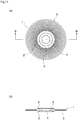
- a conventional structure of a disk type radial vane is shown in Figs. 11(a) and 11(b) .
- a disk-shaped radial vane 1 is constructed by a disk-shaped annular core part 2 in which a tip portion of a brush handle passes through its inner side, and a radial vane part 3 which is formed by extending a lot of thread materials 21 to an outer peripheral direction from a whole region in a peripheral direction of the annular core part 2.
- the annular core part 2 is a weld part to which a lot of thread materials 21 are connected, and an inner side of the annular core part 2 forms a through hole 4 for inserting the handle.
- annular protrusions 5 are integrally formed in both surfaces of the annular core part 2 so as to form a so-called boss part.
- a manufacturing apparatus of the radial vane manufactures the radial vane 1 from a thread bundle 20 which is formed by bundling the thread materials 21 of nylon resin.
- the manufacturing apparatus is provided with a horizontal processing bed 30 and a columnar welding head 40 which is provided on the bed.
- the processing bed 30 is provided with a vertical through hole 31 through which the thread bundle 20 passes.
- the columnar welding head 40 is arranged on the through hole 31 of the processing bed 30 so as to be concentrically vertical, and is driven up and down in the central axis direction by a driving mechanism (not shown) .
- the welding head 40 is a welding horn which carries out welding on the basis of supersonic vibration, and is oscillated and driven by a vibrator (not shown).
- a circular tip face of the welding head 40 is a weld surface 41.
- the thread bundle 20 protrudes at a predetermined amount onto the processing bed 30 through the through hole 31 of the processing bed 30 in a state in which the welding head 40 on the processing bed 30 is in an upward evacuated position.
- the thread bundle 20 is pushed up by a push-up chuck which is provided below the processing bed 30 and is not shown.
- a protruding amount of the thread bundle 20 is set according to a radius of the radial vane 1 to be manufactured/
- the welding head 40 moves down while vibrating from the upward evacuated position, and the thread materials 21 forming the protruding part are uniformly expanded to the periphery by the tip portion of the welding head 40.
- the periphery of the center part of the radially opened thread materials 21 is finally pressed to the periphery of the through hole 31 on the surface of the processing bed 30, by the weld surface 41 of the welding head 40.
- the thread materials 21 in the protruding part of the thread bundle 20 are bent vertically to the periphery and are open radially, and the periphery of the center part of the radially opened thread materials 21 is welded by the weld surface 41 in a tip of the welding head 40. Further, the center part of the radially opened thread materials 21 is promoted to be welded by heat transmission from the periphery of the center part, and finally forms a welded and solidified part 25.
- the boss parts (the annular protrusions 5 and 5) for making the density of flocked fabric in the central axis direction in the brush head small are integrally formed by flowing of the melting material during welding in the periphery of the center part of the radially opened thread materials 21 (during formation of the annular weld part 22).
- the periphery of the center part of the radially opened thread materials 21 and the center part are formed and separated by a cylindrical separation jig doubling as a guide of the thread bundle 20 during welding of the periphery of the center part of the radially opened thread materials 21, and it is possible to achieve reduction of a manufacturing man hour and shortening of a manufacturing time.
- the tip portion of the thread bundle 20 separated from the radial vane 1 forms the welded and solidified part 25, and is cut and removed since the tip portion forms an obstacle at the manufacturing time of the next radial vane 1.
- a length of the removed part reaches about 3 mm to be on the safe side, and a cut loss of the thread bundle 20 generated thereby increases a manufacturing cost, and forms a great obstacle against reduction of the manufacturing cost.
- two removed parts are generated every time one radial vane 1 is manufactured. Therefore, the cut loss of one thread bundle 20 comes to several mm.
- An inner diameter of the through hole 4 in the radial vane 1 basically coincides with an outer diameter of the thread bundle 20.
- the inner diameter of the through hole 4 can be made larger, however, it is necessary to more greatly remove the annular weld part 22 (the annular core part 2), and the cut loss caused by the weld part separation in the thread bundle 20 is further increased.
- the annular core part 2 of the manufactured radial vane 1 is thin and hard (due to no elasticity) since the thread materials 21 are formed by the supersonic welding. Therefore, in the case that the inner diameter of the core part (the diameter of the inside through hole) is smaller than the outer diameter of the shaft part of the handle, not only work becomes hard when the radial vane 1 is fitted to the shaft part, but also the annular core part 2 is easily broken. On the contrary, in the case that the inner diameter of the through hole 4 (the handle insertion hole) formed in the inner side of the annular core part 2 is large, the radial vane 1 is not fixed to the shaft part, and idle running at the using time comes to a problem.
- JP 2004-097692 A discloses a manufacturing apparatus of a disk brush element.
- An object of the present invention is to provide a radial vane which can freely set an inner diameter of a through hole, can make cut loss of a thread bundle as small as possible regardless of magnitude of an inner diameter, and is excellent in economical efficiency, and a method of manufacturing the same.
- the other object of the present invention is to provide a radial vane which can remove the other factors for increasing the manufacturing cost as well as the cut loss, is further economically efficient and has a high-performance, and a method of manufacturing the same.
- the inventors of the present invention have found out a structure and a manufacturing method of a radial vane on the basis of an idea which is absolutely different from the conventional idea, and have completed the present invention.
- the protruding amount of the thread bundle is determined per the minimum unit number, for example, two radial vanes of the double structure, the thread bundle is radially opened while setting the base end side of the protruding part to a starting point, the base end part is thereafter welded, and the vane is separated from the thread bundle in the weld part.
- the cut loss is unavoidably generated according to the weld part separation of the thread bundle per the minimum unit number.
- the inventors of the present invention have thought of a manufacturing method of setting a longitudinal intermediate part of the thread bundle having a length of two radial vanes to a fold-over part, radially opening and superposing the thread bundle in both end sides of the fold-over part while leafing a space in a center part, and annularly welding a spatial periphery of the center part, particularly an outer side of a annular fold-over part formed in the spatial periphery of the center part, by paying attention to the fact that the double structure (the two-ply structure) is proper for the density of the thread material of the vane part in the radial vane.
- a lot of two-folded thread materials are lined up radially in the spatial periphery of the center part. More specifically, a lot of thread materials stereoscopically superposed in the inner peripheral part are dispersed in the peripheral direction toward the outer peripheral side so as to be formed planar. Further, a lot of thread materials stereoscopically superposed in the inner peripheral part are integrated by being annularly welded, and form a radial vane of double structure (two-ply structure).
- the radial vane of the double structure (the two-ply structure) having the great density of the thread materials can be manufactured from one continuous thread bundle without generation of cut loss caused by separation of weld part of the thread bundle.
- a magnitude of the space of the center part can be optionally set, and the magnitude thereof does not affect the cut loss.
- the annular weld part in the spatial periphery of the center part is initially welded completely to the inner peripheral edge of the fold-over part. As a result, the annular weld part comes into contact with space of the center part.
- the annular fold-over part forms a boss part having an arch shaped cross section which is convex to the center side, being thick and having an elasticity, and serves as both a slide part and a grip part which are excellent functionally.
- the annular fold-over part left in the inner side of the annular weld part is a non-weld part or an incomplete weld part, and the thread materials forming the thread bundle are formed by being curved to be round on the basis of the elasticity, the annular fold-over part becomes thicker than the outside annular weld part, and has the greater elasticity than the annular weld part. Further, the thread materials are directed to the central axis direction in the inner peripheral surface of the annular fold-over part.
- the annular fold-over part not only serve a spacer function in the brush head as an effective boss part, but also can make the radial vane be tightly fitted to the shaft without generation of any breakage. As a result, tolerance for inner diameter error of the through hole in the inner side of the fold-over part is increased.
- the radial vane can be smoothly compressed even if the radial vane is somewhat tight. Risk that the annular weld part is broken is extremely small at that time. Further, the radial vane which is once compressed and fitted is hard to come off from the shaft and is hard to rotate in the peripheral direction.
- the fold-over manufacturing method created by the inventors of the present invention it is possible to effectively remove a factor raising the manufacturing cost while making the density of the thread materials in the vane parts of the radial vane reasonable, and making the density of flocked fabric in the central axis direction in the brush head reasonable. Further, it is possible to manufacture the radial vanes having various sizes and shapes by selecting a length of the thread bundle and a position of the fold-over part, and further selecting an inner diameter of the space of the center part.
- the radial vane according to the present invention is made on the basis of the knowledge, and is structurally characterized by a radial vane in a disk-shape including: radial vane parts which are formed by extending a lot of thread materials to an outer peripheral side from a whole region in a peripheral direction of a disk-shaped annular core part having a through hole in a center part, wherein a longitudinal intermediate part of one continuous thread bundle is formed as a fold-over part, thread bundles in both end sides of the fold-over part are radially opened and superposed while leaving a space in a center part, and a spatial periphery of the center part is annularly welded so as to form the core part.
- the radial vane is particularly preferably structured such that an outer side of an annular fold-over part formed in a spatial periphery of the center part is annularly welded so as to form the core part.
- the space of the center part forms a through hole
- the radial vane parts are formed in the periphery of the through hole via the annular core part.
- an annular fold-over part having an arch shaped cross section is formed in the periphery of the through hole and the radial vane parts are formed in further outer side thereof via the annular core part.
- the annular fold-over part is a non-weld part or an incomplete weld part.
- the thread materials forming the thread bundle are not completely bent, but are curved like an arch on the basis of the elasticity of the thread materials.
- the annular fold-over part forms a thick boss part.
- the annular fold-over part also forms a grip part which fixes the vane when the radial vane is fitted to the shaft.
- the annular fold-over part due to a direction of the thread materials in the inner surface of the annular fold-over part, the annular fold-over part also forms an effective slide part.
- the annular fold-over part also forms an effective reinforcing part for the inner annular core part.
- the welding is carried out from both surface sides when the annular core part is welded, and the pressure is easily concentrated, material melting is promoted, and a mechanical strength of the annular core part itself is great.
- the most important structure in the radial vane according to the present invention exists in a point that the vane is formed in both sides by folding over in the intermediate part of the thread bundle, and the annular fold-over part is formed in the periphery of the through hole of the vane center part accordingly, and particularly exists in a point that the thick annular fold-over part constructed by the non-weld part or the incomplete weld part is formed so as to face to the through hole.
- the thickness and the hardness of the annular fold-over part can be adjusted by changing the welding position, and in correspondence to the thickness and the number of the thread materials.
- a method of manufacturing a radial vane according to the present invention is a method of manufacturing a radial vane in a disk-shape including: radial vane parts which are formed by extending a lot of thread materials to an outer peripheral side from a whole region in a peripheral direction of a disk-shaped annular core part having a through hole in a center part, the method including:
- the annular fold-over part is left in the periphery of the through hole, the annular fold-over part being thick, having elasticity and doubling as the boss part, the slide part and the grip part, and the high-performance radial vane mentioned above can be manufactured without any step of separating the vane in the weld part of the thread bundle.
- the respective steps are normally executed step by step in the order of the first opening step, the first welding step, the second opening step and the second welding step, however, the first opening step and the second opening step may be simultaneously executed, and the first welding step and the second welding step may be simultaneously executed.
- one thread bundle may be processed step by step in both end sides of the fold-over part, and may be simultaneously processed symmetrically.
- the rod-like object is preferably inserted previously to the center part. Further, it is rational to use the welding horn used in the first welding step for opening the thread bundle. In the case that the welding horn is used for opening the thread bundle, the rod-like object is preferably protruded from the tip face of the welding horn. According to this structure, it is possible to continuously carry out the first opening step and the first welding step. In the case that the rod-like object is attached to the welding horn, the rod-like object is preferably set to a separate object which is independent from the welding horn for preventing the rod-like object from sympathetically vibrating with the welding horn.
- the fold-over part is welded from an inner side, and it is hard to leave the annular fold-over part which is thick, has the elasticity and doubles as the boss part, the slide part and the grip part in the periphery of the through hole of the radial vane.
- the steps are carried out step by step in the order of the first opening step, the first welding step, the second opening step and the second welding step, it is necessary to maintain a space which is secured in the center part in the first opening step, even in the second opening step and the second welding step which follow the first welding step, in addition to the first welding step, and it is rational to use the rod-like object for this purpose.
- the rod-like object is attached to the welding horn which is used in the second welding step
- the rod-like object is preferably set to a separate object which is independent from the welding horn.
- the rod-like object In the case that the rod-like object is protruded out of the tip face of the welding horn which is used in the first welding step, the rod-like object can be utilized in the second opening step and the second welding step, for maintaining the space which is secured in the center part in the first opening step. Since both the horns are moved close to each other in this case, it is necessary to form a clearance part to which the rod-like object is inserted, in the tip face of the welding horn which is used in the second welding step.
- the clearance part is effective in the case that the first opening step and the second opening step are simultaneously executed, and the first welding step and the second welding step are simultaneously executed. Because both the horns are moved close to each other in this case.
- the radial vane according to the present invention is structured such that the thread materials are radially folded over and welded in the periphery of the through hole of the center part, the density of the thread materials in the vane parts can be set to be identical to the radial vane of the two-ply structure, and can be manufactured without generation of any cut loss caused by the vane separation in the weld part of the thread bundle. As a result, it is possible to reduce the manufacturing cost. Further, it is possible to optionally set the magnitude of the through hole, and the setting does not affect the cut loss, and further the manufacturing cost.
- the thick arch-shaped annular fold-over part constructed by the non-weld part or the incomplete weld part is left in the periphery of the through hole of the center part so as to face to the through hole, it is firstly possible to manufacture without generation of any cut loss caused by the weld part separation of the thread bundle, and it is possible to reduce the manufacturing cost.
- the density of the thread materials in the vane parts can be made identical to the radial vane of the two-ply structure.
- the radial vane can be tightly fixed to the shaft to be fitted, and it is possible to prevent the radial vane from idle running.
- the method of manufacturing the radial vane according to the present invention can efficiently manufacture the radial vane without any vane separation in the weld part of the thread bundle.
- a radial vane according to the present embodiment is used in a cylindrical brush head which is installed to a handle tip portion of a 360-degree toothbrush. More specifically, the brush head in the 360-degree toothbrush is constructed by superposing a desired number of disk-shaped radial vanes in a central axis direction, each of the disk-shaped radial vanes being formed by processing thread materials of nylon resin which is used in the toothbrush, however, the radial vane according to the present embodiment is used in the disk-shaped radial vane which constructs the brush head.
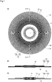
- a radial vane 10 shown in Figs. 1(a) to 1(c) is a double structure vane obtained by integrating and superposing two radial vanes 10a and 10b in a weld part, and is formed from a bundle of a lot of thread materials (thread bundle).
- a center part of the radial vane 10 is provided with a circular through hole 11 to which a tip shaft part of a brush handle passes.
- annular fold-over part 12 protruding like a dome to both surface side and protruding like an arch to an inner surface side is formed in the periphery of the through hole 11 so as to be in contact with the through hole 11, and an annular core part 13 is provided further in an outer side of the annular fold-over part 12, the annular core part 13 being formed by welding thread materials 21, being constructed by a thin annular plate body and having a high intensity.
- a lot of thread materials 21 radially extend out of the annular core part 13 with uniform density in a peripheral direction so as to form annular vane parts 14.
- the thread materials 21 constructing the vane parts 14 include one radial vanes 10a having long bristles and the other radial vanes 10b having short bristles in a mixed manner, the one radial vanes 10a and the other radial vanes 10b being the same number.
- the number of the thread materials 21 in the radial vane 10 is identical in the peripheral direction.
- the thread materials 21 are stereoscopically closed up particularly in the annular fold-over part 12 which is inside the annular core part 13, and are planar in the vane parts 14 which are outside the annular core part 13, thereby being dispersed in the peripheral direction toward an outer peripheral side.
- a manufacturing apparatus shown in Fig. 4 is structured such as to manufacture the radial vane 10, and is provided with a first welding unit 50 and a second welding unit 60 which are arranged side by side, a clamper unit 70 which is in common used in both the welding unit, and a clamper conveyance unit 71 which is installed between both the welding units for horizontally moving.
- the clamper unit 70 has a separately switching type clamper 72, and restricts and releases the thread bundle 20 corresponding to a manufacturing raw material of a radial vane by combining and separating.
- the clamper conveyance unit 71 conveys the material from the first welding unit 50 to the second welding unit 60 on the basis of the horizontal movement of the clamper unit 70.
- the first welding unit 50 forms a first radial vane 10a in the radial vane 10 of the double structure.
- the first welding unit 50 has a thread feeding unit 51, a first processing pedestal 52 and a first welding horn 53 which are concentrically arranged up and down in relation to the clamper conveyance unit 71.
- the thread feeding unit 51 arranged above the clamper conveyance unit 71 discharges downward the thread bundle 20 formed by bundling the thread materials 21 of nylon resin in increments of a predetermined amount.
- the first processing pedestal 52 arranged between the thread feeding unit 51 and the clamper conveyance unit 71 has a through hole 52a which passes through the thread bundle 20 discharged downward by the thread feeding unit 51 from the top to the bottom.
- the first welding horn 53 arranged below the clamper conveyance unit 71 is an upward supersonic transducer which is formed into a columnar shape, and is driven up and down by a driving apparatus (not shown) .
- a circular upper end surface of the first welding horn 53 is a weld surface 53a. More specifically, an annular part except a rod-like convex part 53b in a center part and an annular recessed part 53c in an outer side of the rod-like convex part 53b forms the weld surface 53a.
- the narrow round rod-like convex part 53b is provided on the circular upper end surface of the first welding horn 53 so as to be positioned at the center part, and the annular recessed part 53c is provided so as to surround the rod-like convex part 53b.
- the annular upper end surface in the outer side of the annular recessed part 53c forms the weld surface 53a.
- the rod-like convex part 53b is provided for forming the through hole 11 of the radial vane 10, has an outer diameter which is sufficiently smaller than a thickness of the thread bundle 20 (an inner diameter of the through hole 52a in the first processing pedestal 52), and forms a circular space in the center part of the radially opened thread bundle 20. Further, the rod-like convex part 53b is constructed by a tip protruding part of the round rod-like separate member which is provided in the center part of the first welding horn 53 and passes through the through hole, for preventing resonance with the first welding horn 53.
- the annular recessed part 53c is a clearance part for forming the annular fold-over part 12 of the radial vane 10, particularly for forming the annular fold-over part 12 in the side of the first radial vane 10a.
- the second welding unit 60 forms a second radial vane 10b in the radial vane 10 of the double structure.
- the second welding unit 60 has a second welding horn 61, a second processing pedestal 62 and a vertical guide pin 63 which are concentrically arranged up and down in relation to the clamper conveyance unit 71, the guide pin 63 being used for opening the thread bundle.
- the second welding horn 61 arranged above the clamper conveyance unit 71 is a downward supersonic transducer which is formed into a columnar shape, and is driven up and down by a driving apparatus (not shown).
- a circular lower end surface of the second welding horn 61 is a weld surface 61a. More specifically, an annular lower end surface except an elongated circular recessed part 61b in a center part and a shallow annular recessed part 61c in an outer side of the elongated circular recessed part 61b forms the weld surface 61a.
- the circular recessed part 61b is a clearance hole which receives a guide pin 63 which moves up, and corresponds to a guide hole.
- the annular recessed part 61c is a clearance part for forming the annular fold-over part 12 of the radial vane 10, particularly forming the annular fold-over part 12 in the side of the second radial vane 10b.
- the second processing pedestal 62 arranged below the clamper conveyance unit 71 has a through hole 62a to which the guide pin 63 is inserted.
- An annular recessed part 62b is provided on an upper surface corresponding to a processing surface of the second processing pedestal 62 so as to surround the through hole 62a.
- the annular recessed part 62b is a clearance part which accommodates the annular fold-over part 12 of the radial vane 10, particularly the annular fold-over part 12 formed in the side of the first radial vane 10b.
- the guide pin 63 is driven up and down in a vertical direction by a driving apparatus 63a, is upward inserted to the center part of the thread bundle 20 in a forming process of the second radial vane 10b by being driven to an upper side than the upper surface of the second processing pedestal 62, secures a space in the vane center part, and guides the downward moving second welding horn 61.
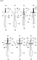
- the thread bundle 20 is discharged to the below of the first processing pedestal 52 through the through hole 52a of the first processing pedestal 52 by the thread feeding unit 51, as shown in Figs. 5(a) and 5(b) .
- a length of the thread bundle 20 discharged to the below of the first processing pedestal 52 is an amount which is necessary for manufacturing the first radial vane 10a.
- the first welding horn 53 starts moving upward from the downward evacuated position while supersonic vibrating and opens the thread materials 21 of the thread bundle 20 discharged to the below of the first processing pedestal 52 to the periphery, as shown in Fig. 5(c) . Further, when the first welding horn 53 goes on moving upward, the thread materials 21 further open to the periphery, and the thread materials 21 opening to the periphery are finally pressed to the periphery of the through hole 52a in the lower surface of the first processing pedestal 52 by the annular weld surface 53a of the first welding horn 53, as shown in Fig. 5(d) .
- the thread materials 21 in the discharge part of the thread bundle 20 is completely opened to the periphery and formed into a radial shape, by the pressing by the weld surface 53a of the first welding horn 53.
- an annular weld part 22a is formed by welding the vicinity of the center part of the radial thread materials 21 which are pressed by the weld surface 53a of the first welding horn 53, that is, an annular part which is sandwiched between the annular weld surface 53a of the first welding head 53 and the surface of the first processing pedestal 52 in the periphery of the through hole 52a.
- the rod-like convex part 53b provided in the center part of the upper end surface of the first welding horn 53 is inserted to the center part of the thread bundle 20 in the final stage of the opening process of the thread bundle 20 and before the welding starts, and is welded in a state in which a circular space is secured in the center part of the thread bundle 20. Since the rod-like convex part 53b is formed as the separate member which is independent from the first welding horn 53 so as to be inhibited resonance with the first welding horn 53, the rod-like convex part 53b prevents the welding of the part which is in contact with the space of the thread materials 21 radially opening to the periphery.
- annular recessed part 53c inhibits the inner edge part of the thread materials 21 radially opening to the periphery (the vicinity of the space) from being welded, and contributes to the formation of the annular fold-over part 12. As mentioned above, the formation of the first radial vane 10a is finished.
- the first welding horn 53 moves downward, and the thread bundle 20 is again discharged to the below of the first processing pedestal 52 by the thread feeding unit 51, as show in Fig. 5(e) .
- the length of the thread bundle 20 discharged to the below of the first processing pedestal 52 is an amount which is necessary for manufacturing the second radial vane 10b.
- the clamper 72 in the separated state at the both side evacuated positions again moves to the combined position, and restricts the thread bundle 20 discharged to the below of the first processing pedestal 52, as shown in Fig. 5(f) .
- the thread bundle 20 is cut along a lower surface of the first processing pedestal 52 by a cutter unit 100, as shown in Fig. 5(g) .
- the clamper unit 70 moves from the first welding unit 50 to the second welding unit 60 while the clamper 72 restricts the thread bundle 20.
- the first radial vane 10a is conveyed to the second welding unit 60 from the first welding unit 50 together with the thread bundle 20 for forming the second radial vane 10b.
- the first radial vane 10a and the thread bundle 20 extending upward from the center part of the first radial vane 10a are fixed between the second welding horn 61 and the second processing pedestal 62, as shown in Fig. 6(a) .
- Fig. 6(a) As a result, as shown in Fig.
- the guide pin 63 starts moving up, passes to the through hole 62a of the second processing pedestal 62, passes to a circular space which is formed in the center part of the first radial vane 10a further above the through hole 62a so as to be inserted to the center part of the thread bundle 20 above the circular space, further passes through the center part of the thread bundle 20, and is inserted to the circular recessed part 61b which is provided in the center part of the lower end surface of the second welding horn 61.
- the clamper 72 opens to both sides, and releases the thread bundle 20, and the second welding horn 61 starts moving down from the upward evacuated position.
- the guide pin 63 starts moving down.
- the first radial vane 10a comes into contact with the upper surface of the second processing pedestal 62, and the thread materials 21 existing in the periphery of the guide pin 63 open to the periphery by being pressed downward by the weld surface 61a of the second welding horn 61 in this state.
- the thread materials 21 completely open to the periphery and are formed into a radial shape on the upper surface of the second processing pedestal 62, as shown in Fig. 6(d) .
- the vicinity of the center part of the radial thread materials 21 is pinched in relation to the upper surface of the second processing pedestal 62 in the periphery of the through hole 62a so as to be welded by the annular weld surface 61a of the second welding horn 61 which supersonic vibrates, and the annular weld part 22b (refer to Fig. 6(d) ) is formed in the second radial vane 10b.
- the annular recessed part 61c formed in the periphery of the circular recessed part 61b of the second welding horn 61 inhibits the inner edge part (the vicinity of the space) of the thread materials 21 opening to the periphery from being welded, and contributes to the formation of the annular fold-over part 12 in the second side. Further, the annular recessed part 62b formed in the periphery of the through hole 62a of the second processing pedestal 62 inhibits deformation of the annular fold-over part 12 which is formed in the first side by the first welding unit 50.
- the guide pin 63 inserted to the circular recessed part 61b of the second welding horn 61 is the rod-like member which is independent from the second welding horn 61, there is no resonance with the second welding horn 61, and there is no risk that the inner surface of the annular fold-over part 12 is welded.
- the radial vane 10 of two-ply structure integrated by the annular weld parts 22a and 22b is formed on the second processing pedestal 62.
- the integrated annular weld parts 22a and 22b form the annular core part 13 of the completed radial vane 10.
- the second welding horn 61 returns to the upward evacuated position, and the guide pin 63 returns to the downward evacuated position, as shown in Fig. 6(e) , thereby releasing the radial vane 10 from the restricted state.
- a manufacturing apparatus shown in Fig. 7 is the other apparatus for manufacturing the radial vane 10, and has a first welding horn 80 and a second welding horn 90 which are concentrically arranged up and down in relation to a clamper conveyance unit 71.
- the feature of the manufacturing apparatus exists in formation of the first radial vane 10a in the radial vane 10 of double structure and formation of the second radial vane 10b at the same position.
- the first welding horn 80 forms the first radial vane 10a in the radial vane 10 of double structure
- the second welding horn 90 forms the second radial vane 10b.
- a clamper unit 70 has a split type clamper 73, and restricts and releases the thread bundle 20 which is a manufacturing raw material of the radial vane by separating and combining the split type clamper 73.
- the clamper 73 doubles as a processing pedestal and is manufactured with high intensity for this purpose.
- the clamper conveyance unit 71 conveys the material from a material receiving position in a left side of the drawing to a processing position between the first welding horn 80 and the second welding horn 90.
- the first welding horn 80 arranged below the clamper conveyance unit 71 is an upward supersonic transducer which is formed into a columnar shape, and is driven up and down by a driving apparatus (not show).
- a circular upper end surface of the first welding horn 80 is a weld surface 81. More specifically, an annular part except a rod-like convex part 82 in an annular recessed part 83 in an outer side of the rod-like convex part 82 forms the weld surface 81.
- the rod-like convex part 82 is provided for forming the through hole 11 of the radial vane 10, has an outer diameter which is smaller than a thickness of the thread bundle 20, is inserted into the center part of the thread bundle 20 in a forming process of the second radial vane 10b so as to form a circular space in the center part of the thread bundle 20, and guides the downward moving second welding horn 61. Further, the rod-like convex part 82 is constructed by a tip protruding part of the round rod-like separate member which is provided in the center part of the first welding horn 80 and passes through the through hole, for preventing resonance with the first welding horn 80, in the same manner as the first welding horn 50 of the manufacturing apparatus shown in Fig 4 .
- the annular recessed part 83 is a clearance part for forming the annular fold-over part 12 of the radial vane 10, particularly for forming the annular fold-over part 12 in the side of the first radial vane, in the same manner as the first welding horn 50.
- the second welding horn 90 arranged above the clamper conveyance unit 71 is a downward supersonic transducer which is formed into a columnar shape, and is driven up and down by a driving apparatus (not shown).
- a circular lower end surface of the second welding horn 90 is a weld surface 91. More specifically, an annular part except an elongated circular recessed part 92 in a center part and a shallow annular recessed part 93 in an outer side of the elongated circular recessed part 92 forms the weld surface 91.
- the circular recessed part 61b is a clearance hole which receives a rod-like convex part 82 which moves up.
- the annular recessed part 61c is a clearance part for forming the annular fold-over part 12 of the radial vane 10, particularly forming the annular fold-over part 12 in the side of the second radial vane 10.
- the clamper unit 70 is positioned in a left part of the clamper conveyance unit 71, and the clamper 73 within the clamper unit 70 restricts the thread bundle 20 discharged out of a thread feeding unit which is arranged above the clamper unit 70 and is not shown.
- the thread bundle 20 is cut by a cutter unit which is provided below the thread feeding unit and is not shown.
- a cut length (a discharge length) of the thread bundle 20 is an amount which is necessary for manufacturing the radial vane 10 of double structure.
- a length of the thread bundle protruding downward from the lower surface (the processing surface) of the clamper 73 doubling as the processing pedestal is an amount which is necessary for the first radial vane 10a
- a length of the thread bundle above the lower surface (the processing surface) of the clamper 73 is an amount which is necessary for the second radial vane 10b.
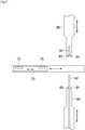
- the clamper unit 70 moves between the first welding horn 80 and the second welding horn 90 while the clamper 73 restricts the thread bundle 20, as shown in Fig. 8(a) , and the thread bundle 20 is conveyed during the while. Then, as shown in Fig. 8(b) , the first welding horn 80 starts moving up from the downward evacuated position while supersonic vibrating, and opens the thread materials 21 of the thread bundle 20 protruding to the below of the clamper 73 to the periphery.
- the thread materials 21 in the downward protruding part of the thread bundle 20 is completely opened to the periphery and formed into a radial shape, by the pressing by the weld surface 81 of the first welding horn 80.
- the first welding horn 80 since the first welding horn 80 supersonic vibrates, the vicinity of the center part of the radial thread materials 21 which are pressed by the weld surface 81 of the first welding horn 80 is annularly welded, and forms an annular weld part 22a (refer to Fig. 8(d) ).
- the rod-like convex part 82 provided in the center part of the upper end surface of the first welding horn 80 is inserted to the center part of the thread bundle 20 in the final stage of the opening process of the thread bundle 20 and before the welding starts, and is welded in a state in which a circular space is secured in the center part of the thread bundle 20 by passing through the center part of the thread bundle 20. Since the rod-like convex part 82 is formed as the separate member which is independent from the first welding horn 80 so as to be inhibited resonance with the first welding horn 80, the rod-like convex part 82 prevents the welding of the part which is in contact with the space of the thread materials 21 radially opening to the periphery.
- annular recessed part 83 inhibits the inner edge part of the thread materials 21 radially opening to the periphery (the vicinity of the space) from being welded, and contributes to the formation of the annular fold-over part 12. As mentioned above, the formation of the first radial vane 10a is finished.
- the clamper 73 opens as shown in Fig. 8(d) .
- the second welding horn 90 starts moving down from the upward evacuated position.
- the thread materials 21 existing in the periphery of the rod-like convex part 82 doubling as the guide pin of the first welding horn 80 opens to the periphery.
- the rod-like convex part 82 of the first welding horn 80 is inserted to the circular recessed part 92 which is the clearance part of the second welding horn 90.
- annular weld part 22b (refer to Fig. 8(g) ) is formed in the second radial vane 10b.
- the annular weld surface 81 of the first welding horn 80 doubles as a processing pedestal in a lower side.
- the rod-like convex part 82 of the first welding horn 80 which is inserted to the circular recessed part 92 corresponding to the clearance part of the second welding horn 90 is a separate member which is independent form the second welding horn 90, the rod-like convex part 82 inhibits the inner surface of the thread materials 21 opening radially to the periphery from being welded.
- the annular recessed part 93 formed in the periphery of the circular recessed part 92 of the second welding horn 90 inhibits the inner edge part (the vicinity of the space) of the thread materials 21 opening radially to the periphery from being welded, and contributes to formation of the annular fold-over part 12 in the side of the second radial vane 10b. Further, the annular recessed part 93 formed in the periphery of the rod-like convex part 82 of the first welding horn 80 inhibits deformation of the annular fold-over part 12 which is formed in the side of the first radial vane 10a.
- the radial vane 10 of two-ply structure integrated by the annular weld parts 22a and 22b is formed at the same position, that is, between the first welding horn 80 and the second welding horn 90.
- the integrated annular weld parts 22a and 22b form the annular core part 13 of the completed radial vane 10, and the annular fold-over part 12 is formed in an inner side of the annular core part 13.
- the manufacturing method has an advantage that the apparatus cost can be reduced, in a point that the clamper 73 and the second welding horn 90 double as the processing pedestal, and any exclusive processing pedestal is not necessary, and a point that the rod-like convex part 82 of the first welding horn 80 doubles as the guide pin and any exclusive guide pin is not necessary.
- a manufacturing apparatus shown in Fig. 9 is basically the same as the manufacturing apparatus shown in Fig. 7 in the apparatus structure.
- the manufacturing apparatus in Fig. 9 is mainly different in a point that a clamper 74 within a clamper unit 70 does not double as the processing pedestal in the same manner as the manufacturing apparatus shown in Fig. 4 , a point that alternatively the clamper 74 doubles as a side welding unit, and a point that a weld surface 91 of a second welding horn 90 doubles as the processing pedestal together with a weld surface 81 of a first welding horn 80.
- the manufacturing apparatus in Fig. 9 is different in timing in a point that the first welding horn 80 arranged below a clamper conveyance unit 71 and the second welding horn 90 arranged above the clamper conveyance unit 71 simultaneously move up and down as shown in Figs. 10(a) to 10(f) .
- the clamper unit 70 is positioned in a left part of the clamper conveyance unit 71, and the thread bundle 20 discharged out of a thread feeding unit which is arranged above the clamper unit 70 and is not shown is restricted by a clamper 72 within the clamper unit 70.
- the thread bundle 20 is cut by a cutter unit which is provided below the thread feeding unit and is not shown.
- a cut length (a discharge length) of the thread bundle 20 is a length which is necessary for manufacturing the radial vane 10 of double structure.
- a length of the thread bundle below the center of a clamp position by a clamper 74 is an amount which is necessary for the first radial vane 10a
- a length of the thread bundle above the center of the clamp position by the clamper 74 is an amount which is necessary for the second radial vane 10b.
- the clamper unit 70 moves between the first welding horn 80 and the second welding horn 90 while the clamper 74 restricts the thread bundle 20, as shown in Fig. 10(a) , and the thread bundle 20 is conveyed during the while. Then, as shown in Fig. 10(b) , the first welding horn 80 starts moving up from the downward evacuated position while supersonic vibrating, and the second welding horn 90 simultaneously starts moving down from the upward evacuated position while supersonic vibrating. As a result, the thread bundles 20 protruding to the up and down of the clamper 74 simultaneously open to the periphery.
- the restricted part of the thread bundle 20 is temporarily welded by the clamper 74 which doubles as the side welding unit, as shown in Fig. 10 (c) .
- the clamper 74 evacuates to both sides, and the first welding horn 80 and the second welding horn 90 further go on moving up and moving down.
- the parts below and above the temporary weld part 23 (refer to Fig.
- the center part of the thread bundle 20 opening to the periphery forms a through hole by inserting a rod-like convex part 82 of the first welding horn 80 thereto.
- the radial vane 10 of double structure (two-ply structure) is manufactured.
- An advantage of the manufacturing method exists in a point that a manufacturing speed is high since the lower radial vane 10a and the upper radial vane 10b are simultaneously formed.
- the rod-like convex part 83 of the first welding horn 80 is a separate member which is independent from the first welding horn 80 and the second welding horn 90, the inner peripheral surface of the annular fold-over part 12 is inhibited from being welded, and the annular recessed part 83 of the first welding horn 80 and the annular recessed part 93 of the second welding horn 90 contribute to the formation of the annular fold-over part 12, in the same manner as the case of the manufacturing method by the manufacturing apparatus shown in Fig. 7 .
- any manufacturing method it is possible to adjust the outer diameter of the radial vane 10 and the respective outer diameters of the radial vanes 10a and 10b constructing the radial vane 10 in a wire range, by changing the cutting amount (the discharge amount) of the thread bundle 20 and the clamp position of the thread bundle 20 by the clampers 72, 73 and 74.
- the radial vane shown in Fig. 2 is structured such that a ring-like reinforcing member 15 is inserted into the annular fold-over part 12. Since the annular fold-over part 12 is formed by curving the thread bundle 20 to an outer side in a state in which a space is formed in the center part, the ring-like reinforcing member 15 may be inserted at the curving time. Further, a mechanical strength in a peripheral direction of the annular weld part is further improved by inserting the ring-like reinforcing member 15 into the annular fold-over part 12.
- the first radial vane 10a and the second radial vane 10b in the radial vane 10 of double structure have the same size, and respective thread lengths in the vane parts 14 are identical.
- the radial vanes 10 having the various sizes and shapes can be manufactured by selecting the length of the thread bundle 20 used for manufacturing and selecting the position of the annular fold-over part 12, as mentioned above.
Landscapes
- Engineering & Computer Science (AREA)
- Manufacturing & Machinery (AREA)
- Chemical & Material Sciences (AREA)
- Materials Engineering (AREA)
- Mechanical Engineering (AREA)
- General Engineering & Computer Science (AREA)
- Brushes (AREA)
- Structures Of Non-Positive Displacement Pumps (AREA)
- Lining Or Joining Of Plastics Or The Like (AREA)
- Harvester Elements (AREA)
- Massaging Devices (AREA)
Claims (7)
- Radialer Flügel (10) in Scheibenform, aufweisend:radiale Flügelteile (14), die dadurch ausgebildet sind, dass sich eine Menge an Fadenmaterialien (21) zu einer Außenumfangsseite erstrecken, und zwar von einem gesamten Gebiet in Umfangsrichtung eines scheibenförmigen ringförmigen Kernteils (13), der ein Durchgangsloch (11) in einem Mittelteil aufweist,wobei ein Längsrichtungsmittelteil eines einzelnen kontinuierlichen Fadenbündels (20) als ein Umfaltteil (12) ausgebildet ist, Fadenbündel (20) aufseiten beider Enden des Umfaltteils radial geöffnet und übereinander angeordnet sind und sie dabei einen Freiraum in einem Mittelteil lassen, und ein räumlicher Umfang des Mittelteils ringförmig verschweißt ist, so dass der Kernteil (13) gebildet wird.
- Radialer Flügel (10) nach Anspruch 1, wobei eine Außenseite eines ringförmigen Umfaltteils (12), der in einem räumlichen Umfang des Mittelteils ausgebildet ist, ringförmig verschweißt ist, so dass der Kernteil (13) gebildet wird.
- Radialer Flügel (10) nach Anspruch 2, wobei der ringförmige Umfaltteil (12) ein buckelartiger Teil ist, der kuppelartig aufseiten beider Flächen vorsteht und gewölbeartig zu einer Innenflächenseite vorsteht, er dick ist und über Elastizität verfügt.
- Verfahren zur Fertigung eines radialen Flügels (10) in scheibenartiger Form, der radiale Flügelteile (14) beinhaltet, die dadurch ausgebildet sind, dass eine Menge an Fadenmaterialien (21) sich zu einer Außenumfangsseite erstreckend angeordnet werden, und zwar von einem gesamten Gebiet in Umfangsrichtung eines scheibenförmigen ringförmigen Kernteils (13), der ein Durchgangsloch (11) in einem Mittelteil aufweist, wobei das Verfahren umfasst:einen ersten Öffnungsschritt, bei dem ein Längsrichtungsmittelteil eines einzelnen kontinuierlichen Fadenbündels als Umfaltteil (12) festgelegt wird, und ein Fadenbündel (20) aufseiten des einen Endes des Umfaltteils zum Umfang hin radial geöffnet wird, und zwar in einem Zustand, bei dem der Umfaltteil als Startpunkt festgelegt ist und ein Freiraum in dem Mittelteil sichergestellt wird;einen ersten Schweißschritt, bei dem das Fadenbündel (20) aufseiten des einen Endes, das zum Umfang hin radial geöffnet ist, in einem räumlichen Umfang des Mittelteils ringförmig verschweißt wird;einen zweiten Öffnungsschritt, bei dem ein Fadenbündel (20) aufseiten des anderen Endes des Umfaltteils zum Umfang hin radial geöffnet wird, und zwar in einem Zustand, bei dem der Umfaltteil als Startpunkt festgelegt ist und ein Freiraum im Mittelteil gewährleistet ist; undeinen zweiten Schweißschritt, bei dem der Faden aufseiten des anderen Endes, das zum Umfang hin radial geöffnet ist, am räumlichen Umfang des Mittelteils ringförmig verschweißt wird.
- Verfahren zur Fertigung eines radialen Flügels (10) nach Anspruch 4, wobei die Fadenbündel aufseiten beider Enden, die sich radial zum Umfang hin öffnen, an der Außenseite des ringförmigen Umfaltteils (12), der an dem räumlichen Umfang des Mittelteils ausgebildet ist, ringförmig verschweißt werden, und zwar bei dem ersten Schweißschritt und dem zweiten Schweißschritt.
- Verfahren zur Fertigung eines radialen Flügels (10) nach Anspruch 4 oder 5, wobei der erste Öffnungsschritt, der erste Schweißschritt, der zweite Öffnungsschritt und der zweite Schweißschritt Schritt für Schritt ausgeführt werden.
- Verfahren zur Fertigung eines radialen Flügels (10) nach Anspruch 4 oder 5, wobei der erste Öffnungsschritt und der zweite Öffnungsschritt gleichzeitig ausgeführt werden, und der erste Schweißschritt und der zweite Schweißschritt in kontinuierlicher Weise gleichzeitig ausgeführt werden.
Priority Applications (1)
| Application Number | Priority Date | Filing Date | Title |
|---|---|---|---|
| PL13740912T PL2807949T3 (pl) | 2012-01-27 | 2013-01-25 | Łopatka promieniowa i sposób jej wytwarzania |
Applications Claiming Priority (2)
| Application Number | Priority Date | Filing Date | Title |
|---|---|---|---|
| JP2012015843 | 2012-01-27 | ||
| PCT/JP2013/051615 WO2013111865A1 (ja) | 2012-01-27 | 2013-01-25 | 放射状羽根及びその製造方法 |
Publications (3)
| Publication Number | Publication Date |
|---|---|
| EP2807949A1 EP2807949A1 (de) | 2014-12-03 |
| EP2807949A4 EP2807949A4 (de) | 2015-12-30 |
| EP2807949B1 true EP2807949B1 (de) | 2019-03-20 |
Family
ID=48873576
Family Applications (1)
| Application Number | Title | Priority Date | Filing Date |
|---|---|---|---|
| EP13740912.4A Active EP2807949B1 (de) | 2012-01-27 | 2013-01-25 | Radialer flügel und herstellungsverfahren dafür |
Country Status (14)
| Country | Link |
|---|---|
| US (1) | US9976432B2 (de) |
| EP (1) | EP2807949B1 (de) |
| JP (3) | JP6042350B2 (de) |
| KR (1) | KR101875993B1 (de) |
| CN (1) | CN104203047B (de) |
| AU (1) | AU2013212860B2 (de) |
| DK (1) | DK2807949T3 (de) |
| EA (1) | EA026178B1 (de) |
| ES (1) | ES2718315T3 (de) |
| MY (1) | MY166476A (de) |
| PL (1) | PL2807949T3 (de) |
| PT (1) | PT2807949T (de) |
| TW (1) | TWI546036B (de) |
| WO (1) | WO2013111865A1 (de) |
Families Citing this family (4)
| Publication number | Priority date | Publication date | Assignee | Title |
|---|---|---|---|---|
| ES2718315T3 (es) * | 2012-01-27 | 2019-07-01 | Stb Higuchi Co Ltd | Paleta radial y método de fabricación de la misma |
| CN105538184A (zh) * | 2015-12-16 | 2016-05-04 | 蓝思科技(长沙)有限公司 | 一种玻璃抛光毛刷及抛光方法与抛光装置 |
| JP7113130B1 (ja) * | 2021-12-17 | 2022-08-04 | 智孝 岩本 | 鼻腔清掃具 |
| CN117017103B (zh) * | 2023-08-16 | 2026-02-06 | 杭州奇丰科技有限公司 | 一种可降解一次性马桶刷及其制造方法 |
Family Cites Families (19)
| Publication number | Priority date | Publication date | Assignee | Title |
|---|---|---|---|---|
| US656374A (en) * | 1899-05-09 | 1900-08-21 | S M Robinson | Rotary brush. |
| US2860921A (en) * | 1954-10-11 | 1958-11-18 | Pittsburgh Plate Glass Co | Method and apparatus for forming rotary brush |
| JPS5248613Y2 (de) * | 1973-11-14 | 1977-11-05 | ||
| JPS63355A (ja) | 1986-06-20 | 1988-01-05 | Toshiba Silicone Co Ltd | メンブレンキ−ボ−ド用ポリオルガノシロキサン組成物 |
| JP4040754B2 (ja) * | 1998-06-22 | 2008-01-30 | 秀夫 富山 | 歯ブラシおよびその製造方法 |
| JP2001276652A (ja) * | 2000-04-03 | 2001-10-09 | Inoue Shokai:Kk | 集塵装置の清掃用ブラシ |
| US7364241B2 (en) | 2002-01-28 | 2008-04-29 | Hideo Tomiyama | Method and device for manufacturing rotary brush and roll tooth brush |
| JP4037653B2 (ja) * | 2002-01-28 | 2008-01-23 | 秀夫 富山 | 回転ブラシの製造方法と装置 |
| JP2004097692A (ja) * | 2002-09-12 | 2004-04-02 | Aiza Planning Kk | 円盤状ブラシ素子の製造装置 |
| JP4854176B2 (ja) * | 2003-06-27 | 2012-01-18 | 株式会社コーワ | 洗浄ブラシ |
| EP1709885B1 (de) | 2004-01-27 | 2016-03-23 | Higuchi Manufactory Co., Ltd. | Radialer flügel für eine zahnbürste, diesen einsetzende zahnbürste und verfahren, vorrichtung zur herstellung des radialen flügels für die zahnbürste und verfahren und vorrichtung zur herstellung eines anderen radialen flügels für eine zahnbürste |
| JP4000355B2 (ja) | 2004-01-27 | 2007-10-31 | 株式会社樋口製作所 | 歯ブラシ用放射状羽根及びこれを使用した歯ブラシ、並びにその歯ブラシ用放射状羽根の製造方法及び製造装置 |
| CN100556334C (zh) * | 2004-01-27 | 2009-11-04 | 株式会社Stb樋口 | 辐射状刷毛和牙刷及该辐射状刷毛的制造方法和制造装置 |
| JP4673802B2 (ja) | 2006-06-21 | 2011-04-20 | 株式会社Stbヒグチ | 放射状羽根及びその製造方法 |
| CN102014693B (zh) * | 2007-12-14 | 2015-01-28 | 高桥淳 | 球形刷 |
| CN101959440B (zh) * | 2008-03-13 | 2012-09-26 | 株式会社鸣门屋 | 圆筒型牙刷 |
| DE102009011171A1 (de) * | 2009-03-04 | 2010-09-09 | Wöhler Brush Tech GmbH | Verfahren für die Herstellung einer Segmentbürste und Hilfsmittel für die Durchführung des Verfahrens |
| JP4756616B1 (ja) | 2010-07-07 | 2011-08-24 | 株式会社Stbヒグチ | 放射状羽根製造方法及び製造装置 |
| ES2718315T3 (es) * | 2012-01-27 | 2019-07-01 | Stb Higuchi Co Ltd | Paleta radial y método de fabricación de la misma |
-
2013
- 2013-01-25 ES ES13740912T patent/ES2718315T3/es active Active
- 2013-01-25 PT PT13740912T patent/PT2807949T/pt unknown
- 2013-01-25 EA EA201400840A patent/EA026178B1/ru active IP Right Revival
- 2013-01-25 MY MYPI2014002200A patent/MY166476A/en unknown
- 2013-01-25 JP JP2013555324A patent/JP6042350B2/ja active Active
- 2013-01-25 DK DK13740912.4T patent/DK2807949T3/da active
- 2013-01-25 US US14/374,427 patent/US9976432B2/en active Active
- 2013-01-25 AU AU2013212860A patent/AU2013212860B2/en active Active
- 2013-01-25 EP EP13740912.4A patent/EP2807949B1/de active Active
- 2013-01-25 CN CN201380017277.9A patent/CN104203047B/zh active Active
- 2013-01-25 WO PCT/JP2013/051615 patent/WO2013111865A1/ja not_active Ceased
- 2013-01-25 PL PL13740912T patent/PL2807949T3/pl unknown
- 2013-01-25 KR KR1020147023062A patent/KR101875993B1/ko active Active
- 2013-01-28 TW TW102103115A patent/TWI546036B/zh active
-
2016
- 2016-10-27 JP JP2016211147A patent/JP6562889B2/ja active Active
- 2016-10-27 JP JP2016211146A patent/JP6802038B2/ja active Active
Non-Patent Citations (1)
| Title |
|---|
| None * |
Also Published As
| Publication number | Publication date |
|---|---|
| WO2013111865A1 (ja) | 2013-08-01 |
| EA026178B1 (ru) | 2017-03-31 |
| EA201400840A1 (ru) | 2014-11-28 |
| JP6802038B2 (ja) | 2020-12-16 |
| JP2017012948A (ja) | 2017-01-19 |
| EP2807949A1 (de) | 2014-12-03 |
| US9976432B2 (en) | 2018-05-22 |
| CN104203047A (zh) | 2014-12-10 |
| AU2013212860A1 (en) | 2014-11-06 |
| TWI546036B (zh) | 2016-08-21 |
| US20140356148A1 (en) | 2014-12-04 |
| TW201334733A (zh) | 2013-09-01 |
| JP2017012947A (ja) | 2017-01-19 |
| PT2807949T (pt) | 2019-04-02 |
| KR20140120344A (ko) | 2014-10-13 |
| ES2718315T3 (es) | 2019-07-01 |
| JP6042350B2 (ja) | 2016-12-14 |
| KR101875993B1 (ko) | 2018-08-02 |
| HK1204532A1 (zh) | 2015-11-27 |
| JP6562889B2 (ja) | 2019-08-21 |
| JPWO2013111865A1 (ja) | 2015-05-11 |
| AU2013212860B2 (en) | 2016-06-30 |
| CN104203047B (zh) | 2016-04-27 |
| EP2807949A4 (de) | 2015-12-30 |
| MY166476A (en) | 2018-06-27 |
| PL2807949T3 (pl) | 2019-09-30 |
| DK2807949T3 (da) | 2019-05-27 |
Similar Documents
| Publication | Publication Date | Title |
|---|---|---|
| US9976432B2 (en) | Radial vane and method of manufacturing same | |
| JP5898411B2 (ja) | インサートカラーの成形方法 | |
| US7992246B2 (en) | Radial vane for tooth brush, tooth brush using the same, and method and device for manufacturing the radial vane for the tooth brush | |
| JP5609291B2 (ja) | 内歯ギア製造用マンドレルおよびそのマンドレルを使用した内歯ギア製造方法と製造装置 | |
| EP1849573B1 (de) | Verfahren und vorrichtung zur zuführung von schmelzharz sowie verfahren zur herstellug eines formteils unter verwendung des zugeführten schmelzharzes | |
| JP2021066054A (ja) | 円環状樹脂部を含む成形品の製造方法 | |
| US20050076460A1 (en) | Method and device for manufacturing rotary brush and roll tooth brush | |
| JP4756616B1 (ja) | 放射状羽根製造方法及び製造装置 | |
| JP3980307B2 (ja) | クラウニングギヤの金型製造方法 | |
| US10398219B2 (en) | Method and apparatus for manufacturing individual brush unit of rotary toothbrush | |
| HK1204532B (en) | Radial vane and method of manufacturing same | |
| JP2015205018A (ja) | 回転式歯ブラシのブラシ単体の製造方法及び製造装置 | |
| JP2011104607A (ja) | 磁石発電機用一体型ローター及び鋼板からの冷間鍛造成形によるその製造方法 | |
| JP2006137602A (ja) | 巻取り機用巻芯 | |
| JP2011045772A (ja) | 放射状羽根 | |
| CN116748801B (zh) | 一种空心戒指胚体的加工方法 | |
| JP2004267478A (ja) | 金属製中空バット及びその製造方法 | |
| CN205521554U (zh) | 一种高频纵扭复合振动海绵阵列取条装置 | |
| CN102639263B (zh) | 用于制造设有通孔的模制件的方法和装置 | |
| CN108381853B (zh) | 一种采血针针头分料盒 | |
| JP4495187B2 (ja) | クラウニングギヤの製造方法 | |
| JP2010046440A (ja) | 内視鏡湾曲管の製造方法 | |
| JP4037739B2 (ja) | ロール歯ブラシ | |
| CN206840236U (zh) | 同轴转动套锁紧结构 | |
| JP4777083B2 (ja) | 食品生地の吐出方法及び装置 |
Legal Events
| Date | Code | Title | Description |
|---|---|---|---|
| PUAI | Public reference made under article 153(3) epc to a published international application that has entered the european phase |
Free format text: ORIGINAL CODE: 0009012 |
|
| 17P | Request for examination filed |
Effective date: 20140729 |
|
| AK | Designated contracting states |
Kind code of ref document: A1 Designated state(s): AL AT BE BG CH CY CZ DE DK EE ES FI FR GB GR HR HU IE IS IT LI LT LU LV MC MK MT NL NO PL PT RO RS SE SI SK SM TR |
|
| DAX | Request for extension of the european patent (deleted) | ||
| RA4 | Supplementary search report drawn up and despatched (corrected) |
Effective date: 20151126 |
|
| RIC1 | Information provided on ipc code assigned before grant |
Ipc: A46D 3/04 20060101AFI20151120BHEP Ipc: A46B 9/04 20060101ALI20151120BHEP Ipc: A46B 3/04 20060101ALI20151120BHEP |
|
| GRAP | Despatch of communication of intention to grant a patent |
Free format text: ORIGINAL CODE: EPIDOSNIGR1 |
|
| STAA | Information on the status of an ep patent application or granted ep patent |
Free format text: STATUS: GRANT OF PATENT IS INTENDED |
|
| INTG | Intention to grant announced |
Effective date: 20180814 |
|
| GRAS | Grant fee paid |
Free format text: ORIGINAL CODE: EPIDOSNIGR3 |
|
| GRAA | (expected) grant |
Free format text: ORIGINAL CODE: 0009210 |
|
| STAA | Information on the status of an ep patent application or granted ep patent |
Free format text: STATUS: THE PATENT HAS BEEN GRANTED |
|
| AK | Designated contracting states |
Kind code of ref document: B1 Designated state(s): AL AT BE BG CH CY CZ DE DK EE ES FI FR GB GR HR HU IE IS IT LI LT LU LV MC MK MT NL NO PL PT RO RS SE SI SK SM TR |
|
| REG | Reference to a national code |
Ref country code: GB Ref legal event code: FG4D |
|
| REG | Reference to a national code |
Ref country code: CH Ref legal event code: EP |
|
| REG | Reference to a national code |
Ref country code: PT Ref legal event code: SC4A Ref document number: 2807949 Country of ref document: PT Date of ref document: 20190402 Kind code of ref document: T Free format text: AVAILABILITY OF NATIONAL TRANSLATION Effective date: 20190321 |
|
| REG | Reference to a national code |
Ref country code: DE Ref legal event code: R096 Ref document number: 602013052605 Country of ref document: DE |
|
| REG | Reference to a national code |
Ref country code: AT Ref legal event code: REF Ref document number: 1109588 Country of ref document: AT Kind code of ref document: T Effective date: 20190415 |
|
| REG | Reference to a national code |
Ref country code: IE Ref legal event code: FG4D |
|
| REG | Reference to a national code |
Ref country code: NL Ref legal event code: FP |
|
| REG | Reference to a national code |
Ref country code: DK Ref legal event code: T3 Effective date: 20190521 |
|
| REG | Reference to a national code |
Ref country code: RO Ref legal event code: EPE |
|
| REG | Reference to a national code |
Ref country code: SE Ref legal event code: TRGR |
|
| REG | Reference to a national code |
Ref country code: ES Ref legal event code: FG2A Ref document number: 2718315 Country of ref document: ES Kind code of ref document: T3 Effective date: 20190701 |
|
| PG25 | Lapsed in a contracting state [announced via postgrant information from national office to epo] |
Ref country code: LT Free format text: LAPSE BECAUSE OF FAILURE TO SUBMIT A TRANSLATION OF THE DESCRIPTION OR TO PAY THE FEE WITHIN THE PRESCRIBED TIME-LIMIT Effective date: 20190320 |
|
| REG | Reference to a national code |
Ref country code: NO Ref legal event code: T2 Effective date: 20190320 |
|
| REG | Reference to a national code |
Ref country code: LT Ref legal event code: MG4D |
|
| PG25 | Lapsed in a contracting state [announced via postgrant information from national office to epo] |
Ref country code: RS Free format text: LAPSE BECAUSE OF FAILURE TO SUBMIT A TRANSLATION OF THE DESCRIPTION OR TO PAY THE FEE WITHIN THE PRESCRIBED TIME-LIMIT Effective date: 20190320 Ref country code: HR Free format text: LAPSE BECAUSE OF FAILURE TO SUBMIT A TRANSLATION OF THE DESCRIPTION OR TO PAY THE FEE WITHIN THE PRESCRIBED TIME-LIMIT Effective date: 20190320 Ref country code: LV Free format text: LAPSE BECAUSE OF FAILURE TO SUBMIT A TRANSLATION OF THE DESCRIPTION OR TO PAY THE FEE WITHIN THE PRESCRIBED TIME-LIMIT Effective date: 20190320 Ref country code: BG Free format text: LAPSE BECAUSE OF FAILURE TO SUBMIT A TRANSLATION OF THE DESCRIPTION OR TO PAY THE FEE WITHIN THE PRESCRIBED TIME-LIMIT Effective date: 20190620 Ref country code: GR Free format text: LAPSE BECAUSE OF FAILURE TO SUBMIT A TRANSLATION OF THE DESCRIPTION OR TO PAY THE FEE WITHIN THE PRESCRIBED TIME-LIMIT Effective date: 20190621 |
|
| PG25 | Lapsed in a contracting state [announced via postgrant information from national office to epo] |
Ref country code: EE Free format text: LAPSE BECAUSE OF FAILURE TO SUBMIT A TRANSLATION OF THE DESCRIPTION OR TO PAY THE FEE WITHIN THE PRESCRIBED TIME-LIMIT Effective date: 20190320 Ref country code: SK Free format text: LAPSE BECAUSE OF FAILURE TO SUBMIT A TRANSLATION OF THE DESCRIPTION OR TO PAY THE FEE WITHIN THE PRESCRIBED TIME-LIMIT Effective date: 20190320 Ref country code: AL Free format text: LAPSE BECAUSE OF FAILURE TO SUBMIT A TRANSLATION OF THE DESCRIPTION OR TO PAY THE FEE WITHIN THE PRESCRIBED TIME-LIMIT Effective date: 20190320 Ref country code: CZ Free format text: LAPSE BECAUSE OF FAILURE TO SUBMIT A TRANSLATION OF THE DESCRIPTION OR TO PAY THE FEE WITHIN THE PRESCRIBED TIME-LIMIT Effective date: 20190320 |
|
| PG25 | Lapsed in a contracting state [announced via postgrant information from national office to epo] |
Ref country code: SM Free format text: LAPSE BECAUSE OF FAILURE TO SUBMIT A TRANSLATION OF THE DESCRIPTION OR TO PAY THE FEE WITHIN THE PRESCRIBED TIME-LIMIT Effective date: 20190320 |
|
| PG25 | Lapsed in a contracting state [announced via postgrant information from national office to epo] |
Ref country code: IS Free format text: LAPSE BECAUSE OF FAILURE TO SUBMIT A TRANSLATION OF THE DESCRIPTION OR TO PAY THE FEE WITHIN THE PRESCRIBED TIME-LIMIT Effective date: 20190720 |
|
| REG | Reference to a national code |
Ref country code: DE Ref legal event code: R097 Ref document number: 602013052605 Country of ref document: DE |
|
| PLBE | No opposition filed within time limit |
Free format text: ORIGINAL CODE: 0009261 |
|
| STAA | Information on the status of an ep patent application or granted ep patent |
Free format text: STATUS: NO OPPOSITION FILED WITHIN TIME LIMIT |
|
| 26N | No opposition filed |
Effective date: 20200102 |
|
| PG25 | Lapsed in a contracting state [announced via postgrant information from national office to epo] |
Ref country code: SI Free format text: LAPSE BECAUSE OF FAILURE TO SUBMIT A TRANSLATION OF THE DESCRIPTION OR TO PAY THE FEE WITHIN THE PRESCRIBED TIME-LIMIT Effective date: 20190320 |
|
| PG25 | Lapsed in a contracting state [announced via postgrant information from national office to epo] |
Ref country code: TR Free format text: LAPSE BECAUSE OF FAILURE TO SUBMIT A TRANSLATION OF THE DESCRIPTION OR TO PAY THE FEE WITHIN THE PRESCRIBED TIME-LIMIT Effective date: 20190320 |
|
| REG | Reference to a national code |
Ref country code: AT Ref legal event code: UEP Ref document number: 1109588 Country of ref document: AT Kind code of ref document: T Effective date: 20190320 |
|
| PG25 | Lapsed in a contracting state [announced via postgrant information from national office to epo] |
Ref country code: MT Free format text: LAPSE BECAUSE OF FAILURE TO SUBMIT A TRANSLATION OF THE DESCRIPTION OR TO PAY THE FEE WITHIN THE PRESCRIBED TIME-LIMIT Effective date: 20190320 Ref country code: CY Free format text: LAPSE BECAUSE OF FAILURE TO SUBMIT A TRANSLATION OF THE DESCRIPTION OR TO PAY THE FEE WITHIN THE PRESCRIBED TIME-LIMIT Effective date: 20190320 |
|
| PG25 | Lapsed in a contracting state [announced via postgrant information from national office to epo] |
Ref country code: MK Free format text: LAPSE BECAUSE OF FAILURE TO SUBMIT A TRANSLATION OF THE DESCRIPTION OR TO PAY THE FEE WITHIN THE PRESCRIBED TIME-LIMIT Effective date: 20190320 |
|
| PGFP | Annual fee paid to national office [announced via postgrant information from national office to epo] |
Ref country code: RO Payment date: 20230125 Year of fee payment: 11 Ref country code: MC Payment date: 20230119 Year of fee payment: 11 Ref country code: LU Payment date: 20230123 Year of fee payment: 11 Ref country code: IE Payment date: 20230119 Year of fee payment: 11 Ref country code: ES Payment date: 20230216 Year of fee payment: 11 Ref country code: DK Payment date: 20230123 Year of fee payment: 11 Ref country code: CH Payment date: 20230130 Year of fee payment: 11 |
|
| PGFP | Annual fee paid to national office [announced via postgrant information from national office to epo] |
Ref country code: PT Payment date: 20230117 Year of fee payment: 11 Ref country code: PL Payment date: 20230118 Year of fee payment: 11 Ref country code: BE Payment date: 20230123 Year of fee payment: 11 |
|
| PGFP | Annual fee paid to national office [announced via postgrant information from national office to epo] |
Ref country code: NL Payment date: 20230124 Year of fee payment: 11 |
|
| REG | Reference to a national code |
Ref country code: DK Ref legal event code: EBP Effective date: 20240131 |
|
| PG25 | Lapsed in a contracting state [announced via postgrant information from national office to epo] |
Ref country code: MC Free format text: LAPSE BECAUSE OF NON-PAYMENT OF DUE FEES Effective date: 20240131 |
|
| PG25 | Lapsed in a contracting state [announced via postgrant information from national office to epo] |
Ref country code: MC Free format text: LAPSE BECAUSE OF NON-PAYMENT OF DUE FEES Effective date: 20240131 |
|
| REG | Reference to a national code |
Ref country code: CH Ref legal event code: PL |
|
| REG | Reference to a national code |
Ref country code: NL Ref legal event code: MM Effective date: 20240201 |
|
| PG25 | Lapsed in a contracting state [announced via postgrant information from national office to epo] |
Ref country code: LU Free format text: LAPSE BECAUSE OF NON-PAYMENT OF DUE FEES Effective date: 20240125 |
|
| PG25 | Lapsed in a contracting state [announced via postgrant information from national office to epo] |
Ref country code: LU Free format text: LAPSE BECAUSE OF NON-PAYMENT OF DUE FEES Effective date: 20240125 |
|
| PG25 | Lapsed in a contracting state [announced via postgrant information from national office to epo] |
Ref country code: PT Free format text: LAPSE BECAUSE OF NON-PAYMENT OF DUE FEES Effective date: 20240725 |
|
| PG25 | Lapsed in a contracting state [announced via postgrant information from national office to epo] |
Ref country code: BE Free format text: LAPSE BECAUSE OF NON-PAYMENT OF DUE FEES Effective date: 20240131 |
|
| PG25 | Lapsed in a contracting state [announced via postgrant information from national office to epo] |
Ref country code: NL Free format text: LAPSE BECAUSE OF NON-PAYMENT OF DUE FEES Effective date: 20240201 |
|
| PG25 | Lapsed in a contracting state [announced via postgrant information from national office to epo] |
Ref country code: CH Free format text: LAPSE BECAUSE OF NON-PAYMENT OF DUE FEES Effective date: 20240131 |
|
| PG25 | Lapsed in a contracting state [announced via postgrant information from national office to epo] |
Ref country code: RO Free format text: LAPSE BECAUSE OF NON-PAYMENT OF DUE FEES Effective date: 20240125 Ref country code: PT Free format text: LAPSE BECAUSE OF NON-PAYMENT OF DUE FEES Effective date: 20240725 Ref country code: NL Free format text: LAPSE BECAUSE OF NON-PAYMENT OF DUE FEES Effective date: 20240201 Ref country code: CH Free format text: LAPSE BECAUSE OF NON-PAYMENT OF DUE FEES Effective date: 20240131 Ref country code: BE Free format text: LAPSE BECAUSE OF NON-PAYMENT OF DUE FEES Effective date: 20240131 |
|
| REG | Reference to a national code |
Ref country code: BE Ref legal event code: MM Effective date: 20240131 |
|
| PG25 | Lapsed in a contracting state [announced via postgrant information from national office to epo] |
Ref country code: DK Free format text: LAPSE BECAUSE OF NON-PAYMENT OF DUE FEES Effective date: 20240131 |
|
| PG25 | Lapsed in a contracting state [announced via postgrant information from national office to epo] |
Ref country code: IE Free format text: LAPSE BECAUSE OF NON-PAYMENT OF DUE FEES Effective date: 20240125 |
|
| PG25 | Lapsed in a contracting state [announced via postgrant information from national office to epo] |
Ref country code: IE Free format text: LAPSE BECAUSE OF NON-PAYMENT OF DUE FEES Effective date: 20240125 Ref country code: DK Free format text: LAPSE BECAUSE OF NON-PAYMENT OF DUE FEES Effective date: 20240131 |
|
| REG | Reference to a national code |
Ref country code: ES Ref legal event code: FD2A Effective date: 20250228 |
|
| PG25 | Lapsed in a contracting state [announced via postgrant information from national office to epo] |
Ref country code: ES Free format text: LAPSE BECAUSE OF NON-PAYMENT OF DUE FEES Effective date: 20240126 |
|
| PG25 | Lapsed in a contracting state [announced via postgrant information from national office to epo] |
Ref country code: PL Free format text: LAPSE BECAUSE OF NON-PAYMENT OF DUE FEES Effective date: 20240125 |
|
| PGFP | Annual fee paid to national office [announced via postgrant information from national office to epo] |
Ref country code: SE Payment date: 20260121 Year of fee payment: 14 |
|
| PGFP | Annual fee paid to national office [announced via postgrant information from national office to epo] |
Ref country code: GB Payment date: 20260122 Year of fee payment: 14 |
|
| PGFP | Annual fee paid to national office [announced via postgrant information from national office to epo] |
Ref country code: NO Payment date: 20260120 Year of fee payment: 14 Ref country code: DE Payment date: 20260129 Year of fee payment: 14 |
|
| PGFP | Annual fee paid to national office [announced via postgrant information from national office to epo] |
Ref country code: AT Payment date: 20260119 Year of fee payment: 14 |
|
| PGFP | Annual fee paid to national office [announced via postgrant information from national office to epo] |
Ref country code: FI Payment date: 20260120 Year of fee payment: 14 Ref country code: IT Payment date: 20260130 Year of fee payment: 14 |
|
| PGFP | Annual fee paid to national office [announced via postgrant information from national office to epo] |
Ref country code: FR Payment date: 20260123 Year of fee payment: 14 |