EP2807529B1 - Interlocking flexible segments formed from a rigid material - Google Patents
Interlocking flexible segments formed from a rigid material Download PDFInfo
- Publication number
- EP2807529B1 EP2807529B1 EP13708282.2A EP13708282A EP2807529B1 EP 2807529 B1 EP2807529 B1 EP 2807529B1 EP 13708282 A EP13708282 A EP 13708282A EP 2807529 B1 EP2807529 B1 EP 2807529B1
- Authority
- EP
- European Patent Office
- Prior art keywords
- rigid material
- interlocking features
- geometric pattern
- apertures
- flex
- Prior art date
- Legal status (The legal status is an assumption and is not a legal conclusion. Google has not performed a legal analysis and makes no representation as to the accuracy of the status listed.)
- Active
Links
Images


Classifications
-
- B—PERFORMING OPERATIONS; TRANSPORTING
- B23—MACHINE TOOLS; METAL-WORKING NOT OTHERWISE PROVIDED FOR
- B23K—SOLDERING OR UNSOLDERING; WELDING; CLADDING OR PLATING BY SOLDERING OR WELDING; CUTTING BY APPLYING HEAT LOCALLY, e.g. FLAME CUTTING; WORKING BY LASER BEAM
- B23K26/00—Working by laser beam, e.g. welding, cutting or boring
- B23K26/36—Removing material
- B23K26/38—Removing material by boring or cutting
-
- G—PHYSICS
- G06—COMPUTING; CALCULATING OR COUNTING
- G06F—ELECTRIC DIGITAL DATA PROCESSING
- G06F1/00—Details not covered by groups G06F3/00 - G06F13/00 and G06F21/00
- G06F1/16—Constructional details or arrangements
- G06F1/1613—Constructional details or arrangements for portable computers
-
- B—PERFORMING OPERATIONS; TRANSPORTING
- B21—MECHANICAL METAL-WORKING WITHOUT ESSENTIALLY REMOVING MATERIAL; PUNCHING METAL
- B21D—WORKING OR PROCESSING OF SHEET METAL OR METAL TUBES, RODS OR PROFILES WITHOUT ESSENTIALLY REMOVING MATERIAL; PUNCHING METAL
- B21D31/00—Other methods for working sheet metal, metal tubes, metal profiles
- B21D31/04—Expanding other than provided for in groups B21D1/00 - B21D28/00, e.g. for making expanded metal
-
- B—PERFORMING OPERATIONS; TRANSPORTING
- B29—WORKING OF PLASTICS; WORKING OF SUBSTANCES IN A PLASTIC STATE IN GENERAL
- B29C—SHAPING OR JOINING OF PLASTICS; SHAPING OF MATERIAL IN A PLASTIC STATE, NOT OTHERWISE PROVIDED FOR; AFTER-TREATMENT OF THE SHAPED PRODUCTS, e.g. REPAIRING
- B29C53/00—Shaping by bending, folding, twisting, straightening or flattening; Apparatus therefor
- B29C53/02—Bending or folding
- B29C53/04—Bending or folding of plates or sheets
- B29C53/06—Forming folding lines by pressing or scoring
- B29C53/063—Forming folding lines by pressing or scoring combined with folding
-
- B—PERFORMING OPERATIONS; TRANSPORTING
- B65—CONVEYING; PACKING; STORING; HANDLING THIN OR FILAMENTARY MATERIAL
- B65D—CONTAINERS FOR STORAGE OR TRANSPORT OF ARTICLES OR MATERIALS, e.g. BAGS, BARRELS, BOTTLES, BOXES, CANS, CARTONS, CRATES, DRUMS, JARS, TANKS, HOPPERS, FORWARDING CONTAINERS; ACCESSORIES, CLOSURES, OR FITTINGS THEREFOR; PACKAGING ELEMENTS; PACKAGES
- B65D85/00—Containers, packaging elements or packages, specially adapted for particular articles or materials
-
- E—FIXED CONSTRUCTIONS
- E05—LOCKS; KEYS; WINDOW OR DOOR FITTINGS; SAFES
- E05D—HINGES OR SUSPENSION DEVICES FOR DOORS, WINDOWS OR WINGS
- E05D1/00—Pinless hinges; Substitutes for hinges
- E05D1/02—Pinless hinges; Substitutes for hinges made of one piece
-
- G—PHYSICS
- G06—COMPUTING; CALCULATING OR COUNTING
- G06F—ELECTRIC DIGITAL DATA PROCESSING
- G06F1/00—Details not covered by groups G06F3/00 - G06F13/00 and G06F21/00
- G06F1/16—Constructional details or arrangements
- G06F1/1613—Constructional details or arrangements for portable computers
- G06F1/1615—Constructional details or arrangements for portable computers with several enclosures having relative motions, each enclosure supporting at least one I/O or computing function
- G06F1/1616—Constructional details or arrangements for portable computers with several enclosures having relative motions, each enclosure supporting at least one I/O or computing function with folding flat displays, e.g. laptop computers or notebooks having a clamshell configuration, with body parts pivoting to an open position around an axis parallel to the plane they define in closed position
-
- G—PHYSICS
- G06—COMPUTING; CALCULATING OR COUNTING
- G06F—ELECTRIC DIGITAL DATA PROCESSING
- G06F1/00—Details not covered by groups G06F3/00 - G06F13/00 and G06F21/00
- G06F1/16—Constructional details or arrangements
- G06F1/1613—Constructional details or arrangements for portable computers
- G06F1/1633—Constructional details or arrangements of portable computers not specific to the type of enclosures covered by groups G06F1/1615 - G06F1/1626
- G06F1/1675—Miscellaneous details related to the relative movement between the different enclosures or enclosure parts
- G06F1/1681—Details related solely to hinges
-
- Y—GENERAL TAGGING OF NEW TECHNOLOGICAL DEVELOPMENTS; GENERAL TAGGING OF CROSS-SECTIONAL TECHNOLOGIES SPANNING OVER SEVERAL SECTIONS OF THE IPC; TECHNICAL SUBJECTS COVERED BY FORMER USPC CROSS-REFERENCE ART COLLECTIONS [XRACs] AND DIGESTS
- Y10—TECHNICAL SUBJECTS COVERED BY FORMER USPC
- Y10T—TECHNICAL SUBJECTS COVERED BY FORMER US CLASSIFICATION
- Y10T428/00—Stock material or miscellaneous articles
- Y10T428/13—Hollow or container type article [e.g., tube, vase, etc.]
Definitions
- the present invention relates generally to creating flexible portions within a rigid material and more specifically, to creating flexible segments for components of electronic devices.
- Many electronic devices, peripheral components or devices may include housings or enclosures made of a relatively rigid material, such as plastic or metal. These types of enclosures are typically at least somewhat rigid in order to provide protection for internal components housed within the enclosures. However, due to the rigidity of the material, in order for these type of enclosures or housings to bend or flex, a separate element, such as a hinge, may need to be connected to the rigid material.
- laptop enclosures may include two separate rigid components interconnected together by one or more hinges that allow the two components to move relative to each other. These additional components, such as hinges, may increase the size of the enclosures and thus the size of the electronic devices or peripheral devices, as well as increase manufacturing costs as additional components may need to be assembled together.
- US 2007/0199176 A1 discloses a living hinge and the appended claims are characterised over this document.
- US 5,028,075 discloses a field blueprint carrier.
- the present invention provides a housing and a method of manufacturing a flexible component as defined in the appended claims.
- Examples of embodiments described herein may take the form of a method for creating an enclosure for an electronic device.
- the method includes providing a rigid material and removing sections of the rigid material to create a geometric pattern of interlocking features.
- the geometric pattern may define the flex of the rigid material.
- inventions may take the form of an enclosure formed of a substantially rigid material.
- the enclosure may include a first plurality of flex apertures defined within the rigid material along a first row and a second plurality of flex apertures defined within the rigid material along a second row.
- the second row is positioned below the first row and the first plurality of flex apertures are misaligned with the second plurality of flex apertures such that a first end of each of the first plurality of flex apertures is in a different vertical plane from a first end of each of the second plurality of flex apertures.
- inventions of the disclosure may take the form of a housing formed of a substantially rigid material.
- the housing may include a first plurality of interlocking features defined within the rigid material, a second plurality of interlocking features defined within the rigid material, and a plurality of flex apertures defined between the first plurality of interlocking features and the second plurality of interlocking features to separate the first plurality of interlocking features from the second plurality of interlocking features.
- the first plurality of interlocking features is movable relative to the second plurality of interlocking features.
- inventions of the disclosure may take the form of a method of manufacturing a flexible component.
- the method includes providing a substantially rigid material and removing portions of the rigid material to create a plurality of flex apertures.
- the flex apertures are defined by interlocking features of the rigid material, the interlocking features are adjacent to each other and spaced apart from one another by the flex apertures.
- Each one of the interlocking features has at least one sidewall and an angle of the sidewall determines a radial bend the rigid material.
- the rigid material formed using the disclosed method may be non-cylindrical, e.g., planar or a three-dimensional object that includes curves but is not substantially cylindrical.
- Some embodiments described herein may take the form of a method for creating a flexible portion or element within a rigid or substantially rigid material.
- rigid material as used herein is meant to encompass rigid materials, semi-rigid (partially flexible materials), and substantially any materials where an increased flexibility may be desired.
- the rigid material may be metal, carbon fiber, composites, ceramics, glass, sapphire, plastic, or the like.
- the flexible portion or portions defined in the rigid material may function as a living hinge or mechanical hinge and allow the rigid material to bend to a predetermined angle in a predetermined direction.
- the flexible portion may be positioned at substantially any location of the rigid material and may span across one or more dimensions of the rigid material (e.g., across a width, length, or height of the rigid material).
- the rigid material may be substantially flat or planar, may represent a three-dimensional object (e.g., a molded or machined component), or the like.
- the flexible portion may be defined by a geometric pattern that may be recessed and/or cut into the rigid material.
- the geometric pattern may define one more movable elements that are interlocked together.
- the movable elements or interlocking features may move relative to adjacent elements, but may be prevented from disconnecting from those adjacent elements.
- the flexible portion may include a plurality of movable interlocked elements, each of which may move a predetermined amount, so that the combination of the plurality of movable elements creates a bend point or area for the rigid material or device or enclosure made from the material.
- the amount of bending may be varied by changing either the degree of movement between individual interlocked movable elements or the shape of one or more elements.
- the bend angle, direction, pitch, and bend or flexing axis may vary with the geometric pattern of the cuts. For example, a first geometric pattern may allow the rigid material to only bend along a single axis where as a second geometric pattern may allow the rigid material to bend along multiple axes.
- the flexing radius may be modified.
- the rigid material may include one or more different patterns, angles, or the like.
- the rigid material may have some sections that are more flexible than others, which may be done by modifying the geometric pattern, the angulation of the pattern, or the like.
- the method for creating the flexible portion may be used to create enclosures for electronic devices, including portable and/or peripheral devices.
- an enclosure for a laptop may be created from a rigid material having a flexible portion defined around approximately a midpoint of the material.
- the flexible portion may allow the rigid material to be folded in half and thus acts as a laptop clamshell.
- a top portion may support a display screen and a bottom portion may support a keyboard, track pad, and the like, while an interior defined by sidewalls of the rigid material may house a variety of electronic components in accordance with conventional laptop computing devices.
- the enclosure (or a portion thereof) may be created from a single rigid material, while still providing flexibility and bending for the enclosure.
- the method may be used to create a flexible cover for an electronic device, such as a cover for a tablet computer or smart phone.
- the method may be used to create a housing or a portion of a housing for headphones.
- the flexible segments may cooperate to form an enclosure encompassing, and protecting, a wire where it enters the enclosure of the headphone.
- the enclosure at the connection location to the wire or cable may flex around one or more axes to provide bending in multiple directions. This flexibility may substantially prevent the enclosure from cracking as the wire moves relative to the earpieces because the connection portion of the earpiece may move, at least in part, with the movement of the communication wire. Additionally, the flexibility may also help to prevent internal wires of the cable from breaking as the flexibility of the housing may increase the radius that the cable or wire may bend, thus providing strain relief to the internal wires as it is bent.
- the method may be used to create a band that may support an electronic device, such as an arm band for holding a portable electronic device on a user's bicep.
- the method may also be used to create strain relief sections for cables, straps, or the like.
- the method may further be used to create handles, cases, bags, purses, or the like.
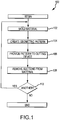
- Fig. 1 is a flow chart for a method 100 for creating a flexible portion within a rigid material.
- the method 100 may begin with operation 102 and the rigid material may be formed or otherwise provided.
- the rigid material may be metal injection molded into a desired shape, the shape of the rigid material may be milled or otherwise cut from a block or sheet of material, or other manufacturing techniques may be used.
- the rigid material may be substantially any material where an increased flexibility is desired.
- the material may include metals, metal alloys, plastics, composite materials (e.g., carbon fiber reinforced plastic, magnetic or conductive materials, glass fiber reinforced materials, or the like), ceramics, sapphire, glasses, printed circuit boards, and the like.
- the rigid material may include a combination of two or more materials connected together (e.g., through adhesive, welding, or the like).
- a first material may be brittle (e.g., glass)
- the material may be laminated or otherwise connected to another less brittle material and then the combined material may be modified using the method 100.
- the formation process used in operation 102 to create the rigid material may be varied depending on the type of material used and/or the size/dimensions of the desired shape. For example, in instances where the material is a hard plastic, injection molding may be used to create the material. However, injection molding may not be desired for other types of materials. Additionally, operation 102 may be optional. For example, in some instances, the rigid material may be provided from another source(e.g., manufacturer) and then may be manipulated, as discussed in more detail below, to provide the flexible portion. Accordingly, in some instances, the rigid material may be in the form of a three-dimensional shape, such as the formed shape of a molded or milled component. Also, it should be noted that the thickness of the rigid material may vary as desired based on the use of the material or shape of the component.
- the shape of the rigid material after operation 102 may not be the final shape of the component as some features such as a small or complex apertures, or finishes such as rounded edges, coatings, painting, and the like may be completed after the method 100 has completed. In other embodiments, such as those where the rigid material may be injection molded, the shape of the rigid material after operation 102 may be substantially the same as the final shape of the rigid material (excluding the changes in shape due to operation 108 discussed in more detail below).
- FIG. 3A illustrates a top plan view of the rigid material after operation 102, and is discussed in more detail below.
- the rigid material may include one or finishes, coatings, decorations, or the like, prior to being manipulated during the method 100. For example, the rigid material may be painted, anodized, layered with one or more coatings, films, or the like, may be applied to the material prior to operations 104 and 106 (discussed below).
- the method 100 may proceed to operation 104 and a geometric pattern may be determined.
- a geometric pattern may be determined.
- the desired bending direction or axis, bending angle or degree, size of apertures within the material, and/or spring rate for the flexible portion may be analyzed to determine the desired geometric pattern.
- the geometric pattern may be created by a processor executing one more algorithms or may be determined by a user.
- the pattern may take into account a number of desired characteristics for the flexibility of the rigid material. For example, increasing the angle of the cuts in the geometric pattern may increase the bending radius of the material. As another example, decreasing the width of the cuts or the removed material may reduce the bending radius.
- geometric pattern In addition to the bending characteristics listed above, there may be additional characteristics of the geometric pattern, such as an aesthetic appearance of the pattern, type of material to be used, and so on that may also be taken into account. Different examples of geometric patterns having one or more of the above-listed characteristics are discussed in more detail below with respect to FIGS. 4A , 5A , 6A , and 7A .
- the geometric pattern chosen may include one or more patterns.
- a first section of the material may be selected to have a first geometric pattern with a first bend radius whereas a second section of the material may be selected to have a second geometric pattern with a second bend radius.
- the two sections of the material may have different bend flexibilities.
- a first side of the material may include a first geometric pattern and a second side of the material may include a second geometric pattern.
- the front side pattern may not match the backside pattern.
- the material may have a first bend radius when bent in a first direction (e.g., the front rolled upon itself) and a second bend radius when bent in a second direction (e.g., the back side rolled upon itself).
- the method 100 may proceed to operation 106 and the pattern may be provided to a cutting mechanism or device.
- the geometric pattern may include sharp corners and/or small apertures.
- the cutting device may be a laser cutting machine, which may use a laser to cut or engrave the geometric pattern into the rigid material.
- the cutting device may be an electrical discharge machine, which may use a wire or probe to remove material in the shape of the geometric pattern.
- the geometric pattern may be provided to the cutting device in the form of data.
- the geometric pattern may be provided to the cutting device by communicating data, such as in the form engineering drawings, computer-aided-design (CAD) files, computer aided manufacturing (CAM) files, or computer numerical control (CNC) files, to a processor or other component within the cutting device.
- data such as in the form engineering drawings, computer-aided-design (CAD) files, computer aided manufacturing (CAM) files, or computer numerical control (CNC) files, to a processor or other component within the cutting device.
- CAD computer-aided-design
- CAM computer aided manufacturing
- CNC computer numerical control
- the method 100 may proceed to operation 108 and the geometric pattern may be incorporated into the rigid material.
- the cutting device may remove sections or portions of the rigid material to form the geometric pattern.
- a laser beam may cut apertures into the rigid material or remove one or more layers of the rigid material to create a recess within the rigid material.
- the laser beam may melt, cut, burn, and/or vaporize the material to create the apertures and/or recesses (engraved portions) within the rigid material.
- the laser may include a multi-axis head that can shift as appropriate to create the angulation and other requirements of the geometric pattern or patterns. For example, the position of the head of the laser may be modified based on the shape of the cuts, while maintaining a single cut through a portion of the material.
- the material may be removed by a pressurized stream water which may optionally include one or more abrasive materials to assist in removing the rigid material.
- a pressurized stream water which may optionally include one or more abrasive materials to assist in removing the rigid material.
- Other cutting devices are also envisioned, but may depend on the complexity of the geometric pattern and/or the type of material for the rigid material. For example, electrical discharge machining (EDM) may be used and a wire or probe may be used to remove material in the shape of the geometric pattern.
- EDM electrical discharge machining
- portions of the geometric pattern may have apertures defined through the rigid material, whereas other portions of the geometric pattern may include recesses defined only through one or two layers of the rigid material (that is, they do not pierce through the rigid material).
- the method 100 may proceed to operation 110.
- operation 110 a computer and/or a user may determine whether another component should be manufactured. If another component is to be manufactured, the method 100 may return to operation 102. However, if another component is not going to be manufactured, the method 100 may terminate at an end state.
- the method may include an additional operation of finalizing or finishing the material.
- one or more coatings, paints, decorations, or finishes may be applied to the material after it has been cut.
- the coatings may be applied to extend around the sidewalls of the material formed by the cuts.
- the material or component may be substantially finalized or otherwise may include the desired finishes prior to being cut. In these instances, the material may not need to be further processed.
- the flexible sections may be created in a rigid material that is mounted within another component or fixture.
- the method 100 may also be used to create components having one or more flexible portions or components that are entirely flexible.
- sheets or large portions of a rigid material may be cut using the method 100, and once cut with a geometric pattern, one or more shapes or smaller components may be cut therefrom.
- a large sheet of a rigid material may be cut with a geometric pattern along its entire length and then a plurality of smaller pieces of the material may be cut or stamped from the large sheet.
- the smaller pieces may be entirely flexible along their entire length, width, or other dimension.
- the rigid material that is cut using the method 100 may include one or more extrusions, apertures, or the like.
- a hole or aperture may be cut into a center of the rigid material (before or after the rigid material is processed using the method 100) and the geometric pattern may extend around the aperture.
- the edges of the aperture may flex due to the geometric pattern, allowing the material surrounding the aperture to remain flexible.
- the method 100 and the geometric patterns discussed in more detail below may be used to create interlocking segments for a material, where the material shape may not be cylindrical.
- the geometric patterns such as those patterns utilizing angled sidewalls or angulation, may allow sheets and other non-cylindrical items to be cut and remain connected together.
- the geometric pattern rather than relying solely on the shape of the object itself to maintain the connection of the components of the geometric pattern, the geometric pattern, rather than the shape of the object, may be used to allow the object to remain interconnected, despite the apertures defined through the object.
- the method 100 may be used to create components and materials for number of different apparatuses and items.
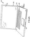
- FIG. 2A is a perspective view of an electronic device 200 including an enclosure 202 formed of a substantially rigid material 230 including a strain relief or flexible portion 204.
- the enclosure 202 may at least partially surround one or more components of the electronic device 200, such as a keyboard 206, track pad 208, and/or a display 210. Further, although not shown, the enclosure 202 may house one or more internal components (also not shown) of the electronic device 200, such as a processor, storage medium, and so on.
- the electronic device 200 in FIG. 2A is illustrated as a computer, other electronic devices are envisioned.
- the enclosure 202 may be used for smart phones, digital music players, display screens or televisions, video game consoles, set top boxes, telephones, and so on.
- the method 100 may also be used to create enclosures (or portions thereof) for one more peripheral devices such as keyboards, mice, connection cables or cords, earphones, and so on.
- the method 100 may be used to create bands (such as an arm band to support an electronic device), garage doors, straps, handles, cases, bags, covers for electronic devices such as tablet computers or electronic reading devices, shades or blinds, and substantially any other components which may require flexibility.
- the enclosure 202 may also include one or more connection apertures 212 defined therein.
- the connection apertures 212 may be defined during the method 100, or in another manner (e.g., while the rigid material is being formed).
- the connection apertures 212 may receive one or more cables, such as communication, data, and/or power cables, to provide a connection port for the cables to the electronic device 200.
- the connection apertures 212 may define an input/output port for universal serial bus (USB) cable, a power cable, or a tip ring sleeve connector.
- USB universal serial bus
- the position, size, number, and/or shape of the connection apertures may be varied depending on the desired connectivity for the electronic device 200.
- FIG. 2B is a side elevation view of the electronic device 200 in a closed position, with the enclosure 202 folded at the flexible portion 204.
- the enclosure 202 may bend so that a top 224 of the enclosure 202 may be folded onto or positioned adjacent to a bottom 226 of the enclosure 202.
- the top 224 may be rotated from a perpendicular, obtuse, or other angular orientation with respect to the bottom 226 (see Fig. 2A ) to a substantially parallel orientation with the respect to the bottom 226.
- the display 210 may be operably connected to the top 224 and may be rotated downwards towards the bottom 226, closing the electronic device 200.
- the enclosure 202 may function as a clamshell in that it may selectively rotate around an axis to position the top 224 relative to the bottom 226.
- both the top and bottom 224, 226 may rotate relative to each other or only one of the top or bottom 224, 226 may rotate.
- the flexible portion 204 and the rotation of the top 224 and bottom 226 will be discussed in more detail below.
- the top 224 and bottom 226 may include one more portions operably connected together.
- the top 224 may include a first or outer portion 214 and a second or inner portion 216 operably connected to define a cavity within the top 224.
- the bottom 226 may include a first or outer portion 218 and a second or inner portion 220 that may be operably connected together to define a cavity within the bottom 226.
- the cavities may receive the one or more internal components of the electronic device 200, as well as may at least partially receive the display 210, the keyboard 206, and/or the track pad 208.
- the outer portion 214, 218 may have substantially the same depth as the respective inner portion 216, 220.
- the outer portion 214 may have a depth that may be approximately half the depth of the cavity and the second portion 216 may have a depth that may have approximately half of the depth of the cavity.
- the outer portions 214, 218 may be formed of a single rigid material 230 and the inner portions 216, 220 may be formed of a separate rigid material that may be operably connected to the outer portions 214, 218.
- the outer portions 214, 218 may include the flexible portion 204 and the inner portions 216, 220 may include an inner or second flexible portion 228.
- the inner flexible portion 228 may be substantially the same as the outer flexible portion 204, so that the inner portions 216, 220 may have approximately the same bend angle and movement range as the outer portions 214, 218.
- the second inner flexible portion 228 defined on the inner portions 216, 220 may be substantially similar to the flexible portion 204.
- the inner portions 216, 220 may be panels or plates, or may have otherwise have a reduced depth compared to the depth of the outer portions 214, 218.
- the top 224 and bottom 226 may include a single portion, and the cavity may be created by removing material through one or more apertures within the top 224 and/or bottom 226.
- FIG. 2C is a side elevation view of the top 224 and bottom 226 formed of a single rigid material 230.
- the top 224 may be at least partially hollowed out to define a surface and four sidewalls extending therefrom, and the display 210 may be operably connected to the surface and sidewalls to enclose the surface.
- the bottom 226 may be formed to receive the keyboard 206, which may form the cover portion for the bottom 226 cavity to cover the internal components.
- the construction of the enclosure 202 may be varied depending on the desired size, dimensions, and/or electronic device 200 be housed by the enclosure 202.
- the respective portions may terminate prior to the flexible portion 204 and thus the flexible portion 204 may form the entire hinge for the top 224 and bottom 226.
- the flexible portion 204 may form the only hinge for the enclosure 202.
- a single material portion may form the entire enclosure 202. That is, the enclosure 202 may be substantially unibody in that it may be formed form a single piece of material.
- the enclosure 202 may bend in order to fold the top 224 towards the bottom 226 or vice versa.
- the flexible portion 204 includes a geometric pattern including interconnected elements that may move or change shape relative to each other in order to provide a flexibility to the rigid material 230 forming the enclosure 202.
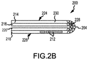
- FIG. 3A is a top perspective view of an at least partially rigid material 230 prior to being formed with the flexible portion 204.
- the rigid material 230 may form one of the outer portions 214, 218 and/or one of the inner portions 216, 220 (see FIG. 2B ). In other embodiments, the rigid material 230 may form both the top 224 and bottom 226 when formed of a single portion (see FIG. 2C ).
- the method 100 may be used to create the flexible portion 204 within the rigid material 230 by defining a geometric pattern into the rigid material 230.
- FIG. 3B is a top plan view of the rigid material 230 including a geometric pattern 232.
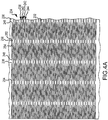
- FIG. 4A is an enlarged top plan view of the rigid material 230 with a geometric pattern 232 formed therein to define the flexible portion 204.
- the geometric pattern 232 may be varied depending on the desired bend angle, position, spring rate, and the like.
- the geometric pattern 232 may be a series of interconnected flex apertures 234 positioned apart from one another to define spacing sections or interlocking features 236.
- a first row 238 may include flex apertures 234 offset from flex apertures 234 within a second row 240 positioned directly below the first row 238. In this manner, the flex apertures 234 of adjacent rows 238, 240 may begin and terminate at varying locations from one another.
- the flex apertures 234, as discussed in more detail below, may be generally linearly shaped apertures formed within the rigid material 230.
- the flex apertures 234 may have a diameter or width that may be selected so that before the rigid material 230 is flexed or bent, the flex apertures 234 may not be substantially visible, improving the aesthetic appearance of the rigid material 230. In other words, prior to bending, the flexible portion 204 may not substantially stand out in appearance from the other surfaces of the rigid material 230.
- the flex apertures 234 may be formed so that the sidewalls surrounding each aperture 234 may have different angular orientations throughout the thickness of the material 230. That is, the flex apertures 234 may have different dimensions through the thickness of the material 230, as the sidewalls 254 may vary in angular orientation (width). The varying dimensions of the flex apertures 234 may allow the rigid material 230 forming the sidewalls 254 to be able to bend or fold, while still maintaining structural strength.
- a third row 242 may include flex apertures 234 that may be substantially aligned with the flex apertures 234 of the first row 238.
- a fourth row 244 may include flex apertures 232 that may be substantially aligned with the flex apertures 234 of the second row 240.
- the flex apertures 234 may be considered to be aligned if a first end 246 of the flex aperture 234 is positioned in a same vertical plane as the first end 246 of another flex aperture 234 and a second end 248 may be positioned in a same vertical plane as the second end 248 of another flex aperture 234 in another row.
- the shape and/or dimensions of the flex apertures 234 may be varied depending on the desired flexibility of the rigid material 230.
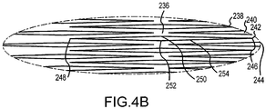
- FIG. 4B is an enlarged view of a portion of the geometric pattern 232 during bending.
- the flex apertures 234 may deform or stretch to be generally diamond shaped as rigid material 230 is stretched.
- the flex apertures 234 may be generally linearly shaped when formed and during bending may stretch for form a diamond shape in order to accommodate the bending force without breaking the material 230.
- the aperture may expand in a triangularly shaped manner, to form two apexes 250, 252, a top apex 250 and a bottom apex 250, 252.
- the two apexes 250, 252 may be aligned with one another, such that the top apex 250 may be positioned over the bottom apex 252. From the two apexes 250, 252 the aperture 234 may descend downwards towards the second end 248. The second end 248 may be substantially laterally aligned with the first end 246. As the bending force is applied to the rigid material 230, the top surface of the flex aperture 234 and the bottom surface may expand away from each other to define the apexes 250, 252. As the bending force increases, the apexes 250, 252 may expand farther away from one another.
- the flex apertures 234 may be diamond shaped when formed, and thus the diamond may be expanded rather than the portions of a linear line expanding into a diamond shape due to the bending force.
- the rigid material 230 may experience some plastic deformation in that the shape of the flex apertures 234 may be somewhat deformed and remain in the diamond shape, rather than the linear shape as originally formed.
- the sidewalls 254 may resiliently return to their original shape, so that after the bending force is removed the shape of the flex apertures 234 when the bending ends, may return to the original linear shape.
- the flex apertures 234 may be defined by sidewalls 254 within the rigid material 230. That is, the flex apertures 234 may be defined by the material surrounding the portions of material removed by the cutting machine during operation 108 of the method 100 in FIG. 1 .
- the sidewalls 254 may allow the size of the flex aperture 234 to vary in dimension as the flexible portion 204 bends. For example, the two apexes 250, 252 may extend away from each other to increase the size of the flex aperture 234 or may extend towards each other to decrease the size of the flex aperture 234. Similarly, the two ends 246, 248 may be compressed towards each other or extend away from each other to vary the size of the flex aperture 234.
- the shape of the flex apertures 234 may change along a depth or thickness of the rigid material 230.
- the flex apertures 234 may have a first size and/or shape and on a second side 262 of the material 230 the flex apertures 234 may have a second size and/or shape. This may be possible as the sidewalls 254 may vary in size along a thickness of the material.
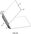
- FIG. 4C is a side perspective view of the rigid material 230 being partially bent.
- FIG. 4D is a side perspective view of the rigid material 230 being more fully bent. As shown best in FIG.
- a first side 260 of the flex aperture 234 may have a smaller diameter and a second side 262 of the flex aperture 234 may have a diameter that is larger than the diameter on the first side 260 of the material 230.
- the sidewalls 254 may form a triangular or frustum shape in profile.
- the first side 260 may include a first geometric pattern and the second side may include a second geometric pattern, one or both patterns may also be selected not only for angulation and bend radius, but also based on aesthetics.
- the first side geometric pattern may be selected based on its bending properties and the second side geometric pattern may be selected based on its aesthetic properties.
- the geometric pattern on both sides of the material may be selected to be substantially identical.
- the triangular shape of the sidewalls 254 may help to prevent the sidewalls 254 of adjacent rows 238, 240 from encountering each other as the rigid material 230 is folded or otherwise bent. Further, the triangular shape of the sidewalls 254 may allow the flex apertures 234 to be more flexible on the inner surface 262 of the material 230 than on the outer surface 260 as the sidewalls 254 may be thicker in width towards the outer surface 260.
- the angular orientation of the sidewalls 254 may also act as a "stop" to prevent, reduce, or resist bending in a particular direction. This may help to protect internal components of the electronic device 200 from damage.
- the angular orientation of the sidewalls 254 may prevent bending past a predetermined angle so that enclosure 202 does not "over bend” and potentially damage internal components from damage. Additionally, the angle of the sidewalls 254 may prevent or substantially resist bending in a particular direction. Further, by varying the thickness or size of the sidewalls 254, the flexible portion may become more or less rigid.
- the shape of the sidewalls 254 may allow the flex apertures 234 to have an increased expansion during bending in the middle of each aperture 234, which may simultaneously minimize stresses on the sidewalls 254 surrounding the apertures 234. This allows the flexible portion 204 to bend without breaking or cracking the rigid material 230, including the sidewalls 254 surrounding each of the flex apertures 234.
- the flexible portion 204 may bend along one or more axes, although the flexible portion 204 may be an integral portion of the rigid material 230.
- the top 224 is shown folded over the bottom 226. To cause the top 224 to be forced towards the bottom 226, a force may be applied to the top 224 compressing it towards the bottom 226 and the flex apertures 234 surrounding a rotation axis A may vary in size. Some of the flex apertures 234 may expand whereas others may decrease. Additionally, the sidewalls 254 surrounding the rotation axis A may be compressed towards one another.
- a thickness of the sidewalls 254 may be decreased on the inner side 262 of the rigid material 230 (due to the shape of the flex apertures 234), which provides additional flexibility to the rigid material 230 and specifically the sidewall 254.
- the rotation axis A may be varied depending on the position of the compression force acting on the top 224.
- the top 224 in a second position of the enclosure 202, the top 224 may be positioned substantially parallel to the bottom 226, and depending on the thickness of the top 224 and/or bottom 226, the top 224 and bottom 226 may be positioned in contact with one another.
- the flexible portion 204 may have a spring force, such that as the flex apertures 234 vary in shape to accommodate the bending forces of the top 224 and/or bottom 226, a spring force may accumulate. In these examples, depending on the weight of the top 226 (and other components operably connected thereto), when the bending force is released, the flexible portion 204 may return to an open or first position.
- the weight of the top 226, the spring force of the flexible portion 204, or the weight of any components operably connected to the top 224 may allow the top 224 to remain in position until adjusted by a user or the like. For instance, after the top 224 has been positioned in the closed position, it may remain substantially in position, at least partially parallel to the bottom 226.
- the geometric pattern 232 may be varied so that the flex apertures 234 may be configured to maintain the enclosure 202 in a predetermined position.
- the geometric pattern 232 may be configured so that the sidewalls 254 may be substantially rigid or may deform slightly so that after the bending force is removed, the rigid material 230 may remain in the bent position.
- certain portions of the geometric pattern 232 may have different shapes, sizes, or other characteristics in order to allow the enclosure 202 to remain in a partially bent or fully bent configuration when the bending force is removed.
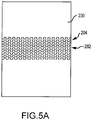
- FIG. 5A is a top plan view of the rigid material 230 including another embodiment of the geometric pattern 282.
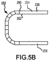
- FIG. 5B is a side elevation view of the rigid material 230 including the geometric pattern 282 in an bent position.
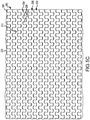
- FIG. 5C is an enlarged top elevation view of flexible portion 204 of FIG. 5A .
- FIG. 5D is an enlarged view of a row of the geometric pattern removed from the rigid material 230.
- FIG. 5E is an enlarged view of the geometric pattern 282 in FIG. 5B .
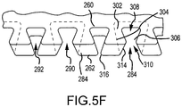
- the geometric pattern 282 in this embodiment may include one or more interlocking features 286 separated from one another by flex apertures 284.
- Each of the interlocking features 286 may move relative to adjacent interlocking features 286 due to the flex apertures 284.
- the flex apertures 284 may not stretch or expand due to the bending force as in the FIG. 4A embodiment, but rather may be increased or decreased due to the relative movement of the interlocking features 286 with respect to each other.
- the interlocking features 286 may be shaped in a number of different manners, which may vary the bending available for the flexible portion 204.
- the interlocking features 286 may include a narrow neck 302 extending from an edge of the rigid material 230 or for interlocking features 286 within an inner portion of the geometric pattern 282, a strip 312 of material.
- the neck 302 may expand outwards forming a head 304.
- the neck 302 and the head 304 may form an inverted frustum, with the head 304 extending away from the edge 306 of the rigid material 230 or an edge of the strip 312.
- Adjacent interlocking features 286 extending from the same edge 306 or strip 312 may be substantially similar. As the flex apertures 284 are defined by the sidewalls of the interlocking features 286, the perimeter of the flex apertures 284 may generally trace the perimeter of the interlocking features 286. As such, the flex apertures 284 may also be generally frustum shaped. However, the flex apertures 284 may be aligned oppositely to the interlocking features 286 (for a single row 298, 300) such that the head or wide portion 308 of the flex aperture 284 may extend into the strip 312 of material, whereas the head 304 of the interlocking features 286 may extend away from the strip 312.
- the flex apertures 284 may be cut between rows to define the interlocking features 286, and as such, the interlocking features 286 of vertically adjacent rows may be received in the flex apertures 284 of the adjacent row and the flex apertures 284 may separate rows of interlocking features 286 from each other.
- the width of the flex apertures 284 may be selected based on a desired bend radius of the material. For example, the finer the width of the flex apertures 284, the smaller the bend radius.
- the flex apertures may be integrally formed apertures that extend along an entire dimension of the rigid material, e.g., along the entire length or width.
- the flex apertures may form curved or undulating lines that separate two portions of the material from each other by a spacing gap. Due to the curved nature of the flex apertures, the interlocking features may be locked together, although the material may be disconnected by the flex apertures.
- the spacing gap or the size of the flex apertures may be varied between a first side of the material and a second side of the material.
- the rows 298, 300 may define strips 312 or lengths of rigid material 230 having interlocking features 286 extending from either side.
- a row 298, 300 may be positioned between two other rows, and thus may include interlocking features 286 extending from opposite sides thereof in order to interlock with the adjacent rows.
- the rigid material may have a plurality of rows that extend along its entire length or width, so that the material may be flexible along an entire dimension.
- the interlocking features 286 may include sidewalls 294 forming an outer perimeter of each respective interlocking feature 286.
- the sidewalls 294 may extend between the inner surface 262 and the outer surface 260.
- the sidewalls 294 may vary in thickness between the inner surface 262 and the outer surface 260.
- the sidewalls 294 may angle upwards from one surface 260, 262 towards the other, such that the angle of the sidewalls 294 with respect to a plane of the outer surface 260 may vary along the depth or thickness of the sidewall 294.
- the sidewalls 294 may be varied in angular orientation from each other (with respect to the plane of the outer surface 260).
- the first sidewall 316 may extend into the flex aperture 284 and a second sidewall 314 may extend away from the flex aperture 284.
- a first sidewall 316 may form a first side of the interlocking feature 286 and the second sidewall 314 may form a second side of the interlocking feature 286. Accordingly, the first side of the interlocking feature 286 may be angled inwards from the outer surface 260 to the inner surface 262 and the second side of the interlocking feature 286 may be angled outwards from the outer surface 260 to the inner surface 262. In some embodiments, laterally adjacent interlocking features 286 may have opposite sides that extend inwards or outwards.
- a first interlocking feature 286 may have a right side extending inwards and a left side extending outwards and a second interlocking feature 286 adjacent to the first interlocking feature 286 may have a right side extending outwards and a left side extending inwards.
- the angled sidewalls may allow the base or rigid material to be shaped in a number of different ways.
- the angled walls may allow the rigid material to have a substantially planar shape and as the material bends (due to the flex apertures), the flex apertures may remain interconnected through the angled walls.
- the pitch of the sidewalls may be varied to vary the bending radius, and the pitch may be variable in the material, such that certain portions of the material may have a first bending radius and other portions of the material may have a second bending radius.
- the interlocking features 286 may appear to be substantially the same dimensions. However, along the inner surface 262, the interlocking features 286 may have varying sidewall 294 thicknesses. For example, a first flex aperture 290 may have a decreased diameter along the inner surface 262 as compared with a second laterally adjacent flex aperture 292. The varying thicknesses, may allow laterally adjacent interlocking features 286 to have differing angles of movement.
- a first interlocking feature 286 received within the first flex aperture 290 may be able to extend downwards towards the inner surface 262, whereas a second interlocking feature 286 received within the second flex aperture 292 may not be able to extend the same amount inwards towards the inner surface 262 due to the decreased size of the second flex aperture 292. Conversely, the first interlocking feature received within the first flex aperture 290 may not be able to extend as far upwards towards the outer surface 260 as the second interlocking feature received within the second flex aperture 292.
- the dimensions of the flex apertures 284 defined by laterally adjacent interlocking features 286 may be different from each other. That is, a first flex aperture 290 may be larger (when viewed from the inner surface 262) than a second flex aperture 292 defined along the same row 298 and laterally adjacent to the first flex aperture 290.
- the varying dimensions of the flex apertures 284 due the varying angular changes of the sidewalls 294, may function to interlock the interlocking features 286 from adjacent rows together, while still allowing the interlocking features 286 to move relative to each other.
- the rigid material 230 may bend along an axis A positioned within the flexible portion 204.
- the force may cause one or more rows 298, 300 of the interlocking features 286 to move relative to each other.
- select interlocking features 286 may extend slightly outwards away from a plane of the material 230.
- the interlocking features 286 may remain substantially secured together. The freedom of movement in at least one direction may provide sufficient strain relief for the rigid material 230 to allow it to bend along the axis A without cracking or breaking.
- rotation axes are possible other than axis A.
- the location of the rotation axis A may depend on the orientation of the geometric pattern 282 as well as the location of the bending force.
- the rotation axis A may be positioned substantially anywhere along the flexible portion 204.
- the rotation axis may be fixed in a single position and may form a living hinge in that the material 230 such that the material 230 may only be able to rotate along that single axis.
- the rotation axis may be defined by the degree of movement between adjacent interlocking features. Accordingly, by restricting or reducing the movement of certain features relative to others, the flexible portion 204 may be configured to only rotate or bend along an axis that may be aligned with other features that may have increased movement relative to other interlocking features.
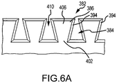
- FIG. 6A is a top plan view of another embodiment of the interlocking features for the geometric pattern 382.
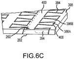
- interlocking features 386 may be movably secured together by a neck portion 410 of the flex apertures 384. That is, a head portion 406 of the interlocking features 386 may substantially touch laterally adjacent head portions 406 so that the neck portion 410 may be relatively narrow.
- the head portions 406 of interlocking rows may be pinched by the head portions 402 of the other row of interlocking features 386.
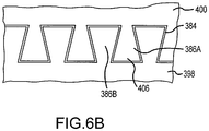
- FIG. 6B is an enlarged view of a first row 398 interlocked with a second row 400.
- FIG. 6C is an enlarged perspective view of the geometric pattern 382.
- first row 398 may be substantially prevented from becoming disconnected from the second row 400.
- the first row 398 may move in a first plane relative to the second row 400, until the sidewalls of the first interlocking feature 386A encounter the sidewalls of the second interlocking features 386B defining the flex aperture 384.
- the sidewalls 394 may be angled as they extend from the outer surface 260 to the inner surface 262, so that the upper portions of the sidewalls 394 may be narrower than the bottom portions of the sidewalls 394. This may allow the top portions of the sidewalls 394 to be movable relative to adjacent interlocking features 386, while the bottom portions of the sidewalls 394 may be secured in place. Additionally, in some embodiments, the sidewalls of the interlocking features 386 for the first row 398 may be oppositely angled from the sidewall of the interlocking features 386 for the second row 400.
- first interlocking feature 386A may also move in a second plane, e.g., in the Y direction away from the plane of the rigid material 230.
- a portion of the first interlocking feature 386A may be pinched within the neck portion 410 of the flex aperture 384 (due to the head portions 406 of adjacent interlocking features) such that the head portion 406 of the first interlocking feature 386A may extend upwards or downwards relative to the second row 400 while remaining secured thereto.
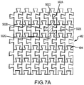
- FIG. 7A is a bottom fragmentary perspective view of another embodiment of the geometric pattern 482 including interlocking features 502 that may bend in two directions.
- FIG. 7B is a top perspective view of the geometric pattern 482.
- FIG. 7C is a top plan view of an interlocking feature 502A removed from the geometric pattern 482.
- rows 498, 500 may be formed of a series of separately interlocked features 502A, 502B, 502C, 502D, 502E.
- the interlocking features 502 may be discrete elements movable connected together to form rows 498, 500. That is, unlike the rows 298, 300 and rows 398, 400 which may include a main portion with adjacent interlocking features extending therefrom, the rows 498, 500 may be formed of separate interlocking features 502 movably connected together.
- each interlocking feature 502A-502E may include a main body 510 with one more locking members extending therefrom.
- the interlocking features 502A-502E may include two legs 512, 514 extending from a first end of the main body 510, a head 520 extending from a second end of the main body 510 opposite the legs 512, 514, and a back portion 516 extending from a first side of the main body 510.
- a second side of the main body 510 may define a receiving aperture 524.
- the receiving aperture 524 may include a neck portion 528 defined by two pinching members 522, 526 that may extend into the receiving aperture 524 at the edge of the second side of the main body 510.
- a head receiving aperture 530 may be defined between the two legs 512, 514 of the interlocking feature 502.
- the edges of the rigid material 230 surrounding the flexible portion 204 may define portions of the interlocking features 502A-502E.
- these portions of interlocking features 502 may operably connect to one or more other interlocking features 502A-502E.
- some portions of the geometric pattern 482 may include non-discrete interlocking features.
- the interlocking features 502A-502E may be operably connected to one or more other interlocking features 502A-502E.
- a first interlocking feature 502A may be operably connected to four other interlocking features 502B, 502C, 502D, and 502E.
- the head 520 of the interlocking feature 502C may be received within the head receiving aperture 530 in the first interlocking feature 502A, where the back portion 516 of the first interlocking feature 502A may be received within the receiving aperture 524 of the second interlocking feature 502B, the head 520 of the first interlocking feature 502A may be received within the head receiving aperture 530 within the fourth interlocking feature 502D, and the back portion 516 of the fifth interlocking feature 502E may be received within the receiving aperture 524 of the first interlocking feature 502A.
- the first interlocking feature 502A may be operably connected to each of the other interlocking features 502B, 502C, 502D, 502E.
- the bending radius of the rigid material or forming material may be modified by varying one or more parameters of the geometric pattern.
- a few parameters include, width of the flex aperture, angulation of the sidewalls boarding the flex apertures or grooves, pitch of the cuts, and thickness of the rigid material.
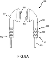
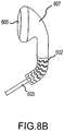
- FIG. 8A is a perspective view of another embodiment of an electronic device 600.
- FIG. 8B is a perspective view of the electronic device in a flexed position.
- the electronic device 600 is an audio output mechanism such as headphones operably and electronically connected to a communication cable 603.
- the communication cable 603 may be operably connected to a speaker 605 by the enclosure 602.
- the enclosure 602 may be formed of the rigid material 230 and may optionally be operably connected to a second portion of top of the enclosure 607.
- the enclosure 602 may be a substantially unitary structure, with the flexible portion 604 being located near the connection to the cable 603.
- the enclosure 602, as shown in FIGS. 8A and 8B may include the geometric pattern 382 of FIGS. 6A-6C along the length of the flexible portion 604. This may allow the enclosure 602 to bend, while still maintaining a rigid connection to the speaker 605.
- the communication cable 603 may be flexible and may move relative to the enclosure 602, which in conventional rigid enclosures may cause the enclosure to wear and/or crack over time. As the enclosure 602 may bend and flex as the communication cable 603 may move.
- the enclosure 602 may be substantially prevented from breaking or cracking due to the movement of the communication cable 603. Additionally, the flexibility of the enclosure 602 may increase the bending radius of the communication cable 603 at the connection location. This may provide a strain relief for the cable 603, which may help to prevent internal wires or the cable 603 itself from breaking due to a bending force. It should be noted that although the enclosure 602 is positioned at the end of the cable closest to the speakers, it should be noted that the enclosure may be positioned at other locations where strain relief may be desired. For example, the flexile portion of the enclosure may be positioned at a second end of the cable that may connect the cable to an electronic device (e.g., through an audio port or the like). In this example, the flexibility of the enclosure may allow the cable to remain connected to the port, but may also flex or bend.
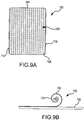
- FIG. 9A is a top plan view of a cover for an electronic device including a geometric pattern defined therein.
- FIG. 9B is a side elevation view of the cover and the electronic device of FIG. 9A with the cover partially retracted.
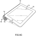
- FIG. 9C is a top perspective view of the cover and the electronic device of FIG. 9A with the cover fully retracted and acting as a support or stand for the electronic device.
- an electronic device 700 includes a cover 704 having the geometric pattern 282 defined therein.
- the geometric pattern 282 may include a plurality of flex apertures 284 and interlocking features that allow the rigid material forming the cover 704 to bend or flex.
- the angulation of the features defined in the cover 704 allows the cover 704 to be rolled around itself.
- the geometric pattern 282 may be substantially the same as the pattern shown in FIG. 5C .
- the flex apertures 284 may be defined in vertical columns that extend along a height of the computing device 702. This configuration may allow the entire cover 704 to flex about an axis parallel to the length axis of the computing device 702.
- the cover 704 may roll or flex in a direction substantially parallel to the direction of the columns of the flex apertures 284.
- the geometric pattern for the cover may be selected based on a desired flex direction, bend radius, and the like.
- the geometric pattern and the bending direction illustrated in FIGS. 9A-9C are illustrative only.
- the cover 704 may lie substantially flat against the top surface of the computing device 702 and may protect a display 712 or other portions of the computing device 702.
- a first end 708 of the cover 704 may be rolled towards a second end 710 forming a rolled portion 706.
- the display 712 or other portions of the computing device 702 may be exposed.
- the cover 702 may be configured to roll and wrap around an edge of the computing device 702 to act as a support stand. For example, a portion of the computing device 702 may rest on the rolled portion 706 of the cover 704, which may allow the computing device 702 to be supported above a surface at a support angle 714.
- the support angle 714 may generally correspond to the outermost radius of the bend portion 706.
- the radial bend of the cover 704 may be defined by geometric pattern, the angulation of the sidewalls defining the flex apertures and the features.
- the second end 710 of the cover 704 may be anchored to an edge 716 of the computing device 702 and may rotate about the edge 716, allowing the rolled portion 706 of the cover 704 to rotate around the edge 716 to a backside of the computing device 702.
Description
- The present invention relates generally to creating flexible portions within a rigid material and more specifically, to creating flexible segments for components of electronic devices.
- Many electronic devices, peripheral components or devices (such as speakers, headphones, keyboards, etc.) may include housings or enclosures made of a relatively rigid material, such as plastic or metal. These types of enclosures are typically at least somewhat rigid in order to provide protection for internal components housed within the enclosures. However, due to the rigidity of the material, in order for these type of enclosures or housings to bend or flex, a separate element, such as a hinge, may need to be connected to the rigid material. For example, laptop enclosures may include two separate rigid components interconnected together by one or more hinges that allow the two components to move relative to each other. These additional components, such as hinges, may increase the size of the enclosures and thus the size of the electronic devices or peripheral devices, as well as increase manufacturing costs as additional components may need to be assembled together.
-
US 2007/0199176 A1 discloses a living hinge and the appended claims are characterised over this document.US 5,028,075 discloses a field blueprint carrier. - In order to mitigate at least some of the issues above, the present invention provides a housing and a method of manufacturing a flexible component as defined in the appended claims.
- Examples of embodiments described herein may take the form of a method for creating an enclosure for an electronic device. The method includes providing a rigid material and removing sections of the rigid material to create a geometric pattern of interlocking features. The geometric pattern may define the flex of the rigid material.
- Other embodiments may take the form of an enclosure formed of a substantially rigid material. The enclosure may include a first plurality of flex apertures defined within the rigid material along a first row and a second plurality of flex apertures defined within the rigid material along a second row. The second row is positioned below the first row and the first plurality of flex apertures are misaligned with the second plurality of flex apertures such that a first end of each of the first plurality of flex apertures is in a different vertical plane from a first end of each of the second plurality of flex apertures. When a bending force is applied to one of the first row or the second row, the first plurality of flex apertures and the second plurality of flex apertures vary in shape or dimension, allowing the rigid material to bend.
- Yet other embodiments of the disclosure may take the form of a housing formed of a substantially rigid material. The housing may include a first plurality of interlocking features defined within the rigid material, a second plurality of interlocking features defined within the rigid material, and a plurality of flex apertures defined between the first plurality of interlocking features and the second plurality of interlocking features to separate the first plurality of interlocking features from the second plurality of interlocking features. The first plurality of interlocking features is movable relative to the second plurality of interlocking features.
- Other embodiments of the disclosure may take the form of a method of manufacturing a flexible component. The method includes providing a substantially rigid material and removing portions of the rigid material to create a plurality of flex apertures. The flex apertures are defined by interlocking features of the rigid material, the interlocking features are adjacent to each other and spaced apart from one another by the flex apertures. Each one of the interlocking features has at least one sidewall and an angle of the sidewall determines a radial bend the rigid material. The rigid material formed using the disclosed method may be non-cylindrical, e.g., planar or a three-dimensional object that includes curves but is not substantially cylindrical.
-
-
FIG. 1 is a flow chart illustrating a method for creating a flexible portion within a rigid material. -
FIG. 2A is a front perspective view of an electronic device including an enclosure formed of a rigid material including a flexible portion. -
FIG. 2B is a side elevation view of the electronic device including a first example of the enclosure. -
FIG. 2C is a side elevation view of the electronic device including a second example of the enclosure. -
Fig. 3A is a top perspective view of the rigid material forming the enclosure prior to being formed with the flexible portion. -
Fig. 3B is a top plan view of the rigid material including a first example of a geometric portion forming the flexible portion. -
Fig. 4A is an enlarged view of the geometric pattern ofFig. 3B during bending. -
Fig. 4B is a further enlarged view of the geometric pattern ofFig. 3B during bending. -
Fig. 4C is a simplified side perspective view of the enclosure ofFig. 2A including the geometric pattern ofFig. 3B with a top portion partially angled with respect to a bottom portion. -
Fig. 4D is a simplified side perspective view of the enclosure ofFig. 2A including the geometric pattern ofFig. 3B with the top portion positioned substantially parallel to the bottom portion. -
Fig. 4E is an enlarged side perspective view of the enclosure ofFig. 4D . -
Fig. 5A is a top plan view of the rigid material including a first embodiment of a geometric pattern forming the flexible portion. -
Fig. 5B is a simplified side perspective view of the enclosure ofFig. 2A including the geometric pattern ofFig. 5A with the top portion positioned substantially parallel to the bottom portion. -
Fig. 5C is an enlarged top plan view of the geometric pattern ofFig. 5A . -
Fig. 5D is an enlarged side elevation view of the geometric pattern ofFig. 5A with the enclosure in the position illustrated inFig. 5B . -
Fig. 5E is an enlarged top perspective view of the geometric pattern ofFig. 5A . -
Fig. 5F is a top perspective view of a row of the geometric pattern ofFig. 5A . -
Fig. 6A is a top perspective view of a row of a second embodiment of the geometric pattern forming the flexible portion. -
Fig. 6B is a top perspective view of two rows of the geometric pattern ofFig. 6A . -
Fig. 6C is a side perspective view of a portion of the geometric pattern ofFig. 6A . -
Fig. 7A is a top plan view of a third embodiment of the geometric pattern forming the flexible portion. -
Fig. 7B is a top perspective view of the geometric pattern ofFig. 7A . -
Fig. 7C is a top plan view of an interlocking feature removed from the geometric pattern ofFig. 7A . -
Fig. 8A is a perspective view of a pair of headphones including an enclosure with the geometric pattern ofFig. 6A defining the flexible portion. -
Fig. 8B is a side perspective view of one of the headphones bending by flexing along the flexible portion of the enclosure. -
Fig. 9A is a top plan view of a cover for an electronic device including a geometric pattern defined therein. -
Fig. 9B is a side elevation view of the cover and the electronic device ofFig. 9A with the cover partially retracted. -
Fig. 9C is a top perspective view of the cover and the electronic device ofFig. 9A with the cover fully retracted and acting as a support or stand for the electronic device. - Some embodiments described herein may take the form of a method for creating a flexible portion or element within a rigid or substantially rigid material. It should be noted that the term rigid material as used herein is meant to encompass rigid materials, semi-rigid (partially flexible materials), and substantially any materials where an increased flexibility may be desired. For example, the rigid material may be metal, carbon fiber, composites, ceramics, glass, sapphire, plastic, or the like. The flexible portion or portions defined in the rigid material may function as a living hinge or mechanical hinge and allow the rigid material to bend to a predetermined angle in a predetermined direction. In some embodiments, the flexible portion may be positioned at substantially any location of the rigid material and may span across one or more dimensions of the rigid material (e.g., across a width, length, or height of the rigid material). In some instances, the rigid material may be substantially flat or planar, may represent a three-dimensional object (e.g., a molded or machined component), or the like.
- The flexible portion may be defined by a geometric pattern that may be recessed and/or cut into the rigid material. In some embodiments, the geometric pattern may define one more movable elements that are interlocked together. The movable elements or interlocking features may move relative to adjacent elements, but may be prevented from disconnecting from those adjacent elements. The flexible portion may include a plurality of movable interlocked elements, each of which may move a predetermined amount, so that the combination of the plurality of movable elements creates a bend point or area for the rigid material or device or enclosure made from the material. The amount of bending, that is, the maximum angle through which the rigid material can deform if all movable interlocked elements translate to their maximums, may be varied by changing either the degree of movement between individual interlocked movable elements or the shape of one or more elements. Similarly, the bend angle, direction, pitch, and bend or flexing axis may vary with the geometric pattern of the cuts. For example, a first geometric pattern may allow the rigid material to only bend along a single axis where as a second geometric pattern may allow the rigid material to bend along multiple axes. As another example, by varying the angulation of the shape of the elements, the flexing radius may be modified.
- The rigid material may include one or more different patterns, angles, or the like. In other words, the rigid material may have some sections that are more flexible than others, which may be done by modifying the geometric pattern, the angulation of the pattern, or the like.
- In some embodiments, the method for creating the flexible portion may be used to create enclosures for electronic devices, including portable and/or peripheral devices. For example, an enclosure for a laptop may be created from a rigid material having a flexible portion defined around approximately a midpoint of the material. The flexible portion may allow the rigid material to be folded in half and thus acts as a laptop clamshell. A top portion may support a display screen and a bottom portion may support a keyboard, track pad, and the like, while an interior defined by sidewalls of the rigid material may house a variety of electronic components in accordance with conventional laptop computing devices. In this manner, the enclosure (or a portion thereof) may be created from a single rigid material, while still providing flexibility and bending for the enclosure. As another example, the method may be used to create a flexible cover for an electronic device, such as a cover for a tablet computer or smart phone.
- As another example, the method may be used to create a housing or a portion of a housing for headphones. In this example, the flexible segments may cooperate to form an enclosure encompassing, and protecting, a wire where it enters the enclosure of the headphone. The enclosure at the connection location to the wire or cable may flex around one or more axes to provide bending in multiple directions. This flexibility may substantially prevent the enclosure from cracking as the wire moves relative to the earpieces because the connection portion of the earpiece may move, at least in part, with the movement of the communication wire. Additionally, the flexibility may also help to prevent internal wires of the cable from breaking as the flexibility of the housing may increase the radius that the cable or wire may bend, thus providing strain relief to the internal wires as it is bent.
- Yet other examples include using the method to create bands, straps, or cables having flexible sections or that may be substantially flexible. As a specific example, the method may be used to create a band that may support an electronic device, such as an arm band for holding a portable electronic device on a user's bicep. As another specific example, the method may also be used to create strain relief sections for cables, straps, or the like. The method may further be used to create handles, cases, bags, purses, or the like.
- Turning now to the figures, a method for creating a flexible portion in a rigid material will be discussed in more detail.
Fig. 1 is a flow chart for amethod 100 for creating a flexible portion within a rigid material. Themethod 100 may begin withoperation 102 and the rigid material may be formed or otherwise provided. In some embodiments, the rigid material may be metal injection molded into a desired shape, the shape of the rigid material may be milled or otherwise cut from a block or sheet of material, or other manufacturing techniques may be used. The rigid material may be substantially any material where an increased flexibility is desired. For example the material may include metals, metal alloys, plastics, composite materials (e.g., carbon fiber reinforced plastic, magnetic or conductive materials, glass fiber reinforced materials, or the like), ceramics, sapphire, glasses, printed circuit boards, and the like. Additionally, the rigid material may include a combination of two or more materials connected together (e.g., through adhesive, welding, or the like). As one example, in instances where a first material may be brittle (e.g., glass), the material may be laminated or otherwise connected to another less brittle material and then the combined material may be modified using themethod 100. - The formation process used in
operation 102 to create the rigid material may be varied depending on the type of material used and/or the size/dimensions of the desired shape. For example, in instances where the material is a hard plastic, injection molding may be used to create the material. However, injection molding may not be desired for other types of materials. Additionally,operation 102 may be optional. For example, in some instances, the rigid material may be provided from another source(e.g., manufacturer) and then may be manipulated, as discussed in more detail below, to provide the flexible portion. Accordingly, in some instances, the rigid material may be in the form of a three-dimensional shape, such as the formed shape of a molded or milled component. Also, it should be noted that the thickness of the rigid material may vary as desired based on the use of the material or shape of the component. - The shape of the rigid material after
operation 102 may not be the final shape of the component as some features such as a small or complex apertures, or finishes such as rounded edges, coatings, painting, and the like may be completed after themethod 100 has completed. In other embodiments, such as those where the rigid material may be injection molded, the shape of the rigid material afteroperation 102 may be substantially the same as the final shape of the rigid material (excluding the changes in shape due tooperation 108 discussed in more detail below).FIG. 3A illustrates a top plan view of the rigid material afteroperation 102, and is discussed in more detail below. Alternatively or additionally, the rigid material may include one or finishes, coatings, decorations, or the like, prior to being manipulated during themethod 100. For example, the rigid material may be painted, anodized, layered with one or more coatings, films, or the like, may be applied to the material prior tooperations 104 and 106 (discussed below). - After
operation 102 and the shape of the rigid material is created, themethod 100 may proceed tooperation 104 and a geometric pattern may be determined. Inoperation 104, the desired bending direction or axis, bending angle or degree, size of apertures within the material, and/or spring rate for the flexible portion may be analyzed to determine the desired geometric pattern. The geometric pattern may be created by a processor executing one more algorithms or may be determined by a user. The pattern may take into account a number of desired characteristics for the flexibility of the rigid material. For example, increasing the angle of the cuts in the geometric pattern may increase the bending radius of the material. As another example, decreasing the width of the cuts or the removed material may reduce the bending radius. In addition to the bending characteristics listed above, there may be additional characteristics of the geometric pattern, such as an aesthetic appearance of the pattern, type of material to be used, and so on that may also be taken into account. Different examples of geometric patterns having one or more of the above-listed characteristics are discussed in more detail below with respect toFIGS. 4A ,5A ,6A , and7A . - The geometric pattern chosen may include one or more patterns. For example, a first section of the material may be selected to have a first geometric pattern with a first bend radius whereas a second section of the material may be selected to have a second geometric pattern with a second bend radius. In this manner, the two sections of the material (when finished) may have different bend flexibilities. As another example, a first side of the material may include a first geometric pattern and a second side of the material may include a second geometric pattern. In other words, the front side pattern may not match the backside pattern. In this manner, the material may have a first bend radius when bent in a first direction (e.g., the front rolled upon itself) and a second bend radius when bent in a second direction (e.g., the back side rolled upon itself).
- Once the geometric pattern has been determined, the
method 100 may proceed tooperation 106 and the pattern may be provided to a cutting mechanism or device. In some embodiments, the geometric pattern may include sharp corners and/or small apertures. In these embodiments, the cutting device may be a laser cutting machine, which may use a laser to cut or engrave the geometric pattern into the rigid material. In other embodiments, the cutting device may be an electrical discharge machine, which may use a wire or probe to remove material in the shape of the geometric pattern. In either of these embodiments, the geometric pattern may be provided to the cutting device in the form of data. For example, the geometric pattern may be provided to the cutting device by communicating data, such as in the form engineering drawings, computer-aided-design (CAD) files, computer aided manufacturing (CAM) files, or computer numerical control (CNC) files, to a processor or other component within the cutting device. - After
operation 106, themethod 100 may proceed tooperation 108 and the geometric pattern may be incorporated into the rigid material. In some embodiments, the cutting device may remove sections or portions of the rigid material to form the geometric pattern. For example, in instances where the cutting device is a laser, a laser beam may cut apertures into the rigid material or remove one or more layers of the rigid material to create a recess within the rigid material. The laser beam may melt, cut, burn, and/or vaporize the material to create the apertures and/or recesses (engraved portions) within the rigid material. In embodiments utilizing a laser as the cutting mechanism, the laser may include a multi-axis head that can shift as appropriate to create the angulation and other requirements of the geometric pattern or patterns. For example, the position of the head of the laser may be modified based on the shape of the cuts, while maintaining a single cut through a portion of the material. - In other embodiments, for example, where the cutting device is a water jet or other pressurized cutter, the material may be removed by a pressurized stream water which may optionally include one or more abrasive materials to assist in removing the rigid material. Other cutting devices are also envisioned, but may depend on the complexity of the geometric pattern and/or the type of material for the rigid material. For example, electrical discharge machining (EDM) may be used and a wire or probe may be used to remove material in the shape of the geometric pattern.
- It should be noted that certain portions of the geometric pattern may have apertures defined through the rigid material, whereas other portions of the geometric pattern may include recesses defined only through one or two layers of the rigid material (that is, they do not pierce through the rigid material).
- After
operation 108 in which the geometric pattern has been engraved and/or cut into the rigid material, themethod 100 may proceed tooperation 110. Inoperation 110, a computer and/or a user may determine whether another component should be manufactured. If another component is to be manufactured, themethod 100 may return tooperation 102. However, if another component is not going to be manufactured, themethod 100 may terminate at an end state. - Alternatively, in instances where the material and/or the component may not be finalized or otherwise requires additional processing, the method may include an additional operation of finalizing or finishing the material. For example, one or more coatings, paints, decorations, or finishes may be applied to the material after it has been cut. In instances where finishes may be applied after the material has been cut with the geometric pattern, the coatings may be applied to extend around the sidewalls of the material formed by the cuts. However, as discussed above, in some embodiments, the material or component may be substantially finalized or otherwise may include the desired finishes prior to being cut. In these instances, the material may not need to be further processed. Moreover, it should be noted that the flexible sections may be created in a rigid material that is mounted within another component or fixture.
- The
method 100 may also be used to create components having one or more flexible portions or components that are entirely flexible. In some embodiments, sheets or large portions of a rigid material may be cut using themethod 100, and once cut with a geometric pattern, one or more shapes or smaller components may be cut therefrom. For example, a large sheet of a rigid material may be cut with a geometric pattern along its entire length and then a plurality of smaller pieces of the material may be cut or stamped from the large sheet. In this example, the smaller pieces may be entirely flexible along their entire length, width, or other dimension. As another example, the rigid material that is cut using themethod 100 may include one or more extrusions, apertures, or the like. As a specific example, a hole or aperture may be cut into a center of the rigid material (before or after the rigid material is processed using the method 100) and the geometric pattern may extend around the aperture. In this example, the edges of the aperture may flex due to the geometric pattern, allowing the material surrounding the aperture to remain flexible. - The
method 100 and the geometric patterns discussed in more detail below may be used to create interlocking segments for a material, where the material shape may not be cylindrical. The geometric patterns, such as those patterns utilizing angled sidewalls or angulation, may allow sheets and other non-cylindrical items to be cut and remain connected together. In other words, rather than relying solely on the shape of the object itself to maintain the connection of the components of the geometric pattern, the geometric pattern, rather than the shape of the object, may be used to allow the object to remain interconnected, despite the apertures defined through the object. Thus, themethod 100 may be used to create components and materials for number of different apparatuses and items. - Illustrative enclosures formed using the
method 100 ofFIG. 1 will now be discussed.FIG. 2A is a perspective view of anelectronic device 200 including anenclosure 202 formed of a substantiallyrigid material 230 including a strain relief orflexible portion 204. Theenclosure 202 may at least partially surround one or more components of theelectronic device 200, such as akeyboard 206,track pad 208, and/or adisplay 210. Further, although not shown, theenclosure 202 may house one or more internal components (also not shown) of theelectronic device 200, such as a processor, storage medium, and so on. It should be noted that, although theelectronic device 200 inFIG. 2A is illustrated as a computer, other electronic devices are envisioned. For example, theenclosure 202 may be used for smart phones, digital music players, display screens or televisions, video game consoles, set top boxes, telephones, and so on. Themethod 100 may also be used to create enclosures (or portions thereof) for one more peripheral devices such as keyboards, mice, connection cables or cords, earphones, and so on. Further, themethod 100 may be used to create bands (such as an arm band to support an electronic device), garage doors, straps, handles, cases, bags, covers for electronic devices such as tablet computers or electronic reading devices, shades or blinds, and substantially any other components which may require flexibility. - The
enclosure 202 may also include one ormore connection apertures 212 defined therein. The connection apertures 212 may be defined during themethod 100, or in another manner (e.g., while the rigid material is being formed). The connection apertures 212 may receive one or more cables, such as communication, data, and/or power cables, to provide a connection port for the cables to theelectronic device 200. For example, theconnection apertures 212 may define an input/output port for universal serial bus (USB) cable, a power cable, or a tip ring sleeve connector. The position, size, number, and/or shape of the connection apertures may be varied depending on the desired connectivity for theelectronic device 200. - The
flexible portion 204 of theenclosure 202 may allow the enclosure 202 (specifically, the rigid material 230) to bend in at least one direction.FIG. 2B is a side elevation view of theelectronic device 200 in a closed position, with theenclosure 202 folded at theflexible portion 204. Theenclosure 202 may bend so that a top 224 of theenclosure 202 may be folded onto or positioned adjacent to abottom 226 of theenclosure 202. In other words, the top 224 may be rotated from a perpendicular, obtuse, or other angular orientation with respect to the bottom 226 (seeFig. 2A ) to a substantially parallel orientation with the respect to the bottom 226. For example, in instances where theelectronic device 200 is a laptop computer, thedisplay 210 may be operably connected to the top 224 and may be rotated downwards towards the bottom 226, closing theelectronic device 200. In this manner, theenclosure 202 may function as a clamshell in that it may selectively rotate around an axis to position the top 224 relative to the bottom 226. It should be noted that in other embodiments, both the top andbottom bottom flexible portion 204 and the rotation of the top 224 and bottom 226 will be discussed in more detail below. - With reference to
Figs. 2A and2B , the top 224 and bottom 226 may include one more portions operably connected together. The top 224 may include a first orouter portion 214 and a second orinner portion 216 operably connected to define a cavity within the top 224. Similarly, the bottom 226 may include a first orouter portion 218 and a second or inner portion 220 that may be operably connected together to define a cavity within thebottom 226. The cavities (not shown) may receive the one or more internal components of theelectronic device 200, as well as may at least partially receive thedisplay 210, thekeyboard 206, and/or thetrack pad 208. - In some embodiments, the
outer portion inner portion 216, 220. In other words, theouter portion 214 may have a depth that may be approximately half the depth of the cavity and thesecond portion 216 may have a depth that may have approximately half of the depth of the cavity. In these embodiments, theouter portions rigid material 230 and theinner portions 216, 220 may be formed of a separate rigid material that may be operably connected to theouter portions - With reference to
Fig. 2B , in embodiments where the top 224 and bottom 226 include two ormore portions outer portions flexible portion 204 and theinner portions 216, 220 may include an inner or secondflexible portion 228. The innerflexible portion 228 may be substantially the same as the outerflexible portion 204, so that theinner portions 216, 220 may have approximately the same bend angle and movement range as theouter portions flexible portion 228 defined on theinner portions 216, 220 may be substantially similar to theflexible portion 204. - In other embodiments, the
inner portions 216, 220 may be panels or plates, or may have otherwise have a reduced depth compared to the depth of theouter portions bottom 226.FIG. 2C is a side elevation view of the top 224 and bottom 226 formed of a singlerigid material 230. For example, the top 224 may be at least partially hollowed out to define a surface and four sidewalls extending therefrom, and thedisplay 210 may be operably connected to the surface and sidewalls to enclose the surface. Similarly, the bottom 226 may be formed to receive thekeyboard 206, which may form the cover portion for the bottom 226 cavity to cover the internal components. The construction of theenclosure 202 may be varied depending on the desired size, dimensions, and/orelectronic device 200 be housed by theenclosure 202. - In embodiments where either the
outer portions inner portions 216, 220 may from a panel or cover, the respective portions may terminate prior to theflexible portion 204 and thus theflexible portion 204 may form the entire hinge for the top 224 andbottom 226. Similarly, in embodiments where the top 224 and bottom 226 are formed of a single portion as shown inFIG. 2C , theflexible portion 204 may form the only hinge for theenclosure 202. In these embodiments, a single material portion may form theentire enclosure 202. That is, theenclosure 202 may be substantially unibody in that it may be formed form a single piece of material. However, due to theflexible portion 204, discussed in more detail below, theenclosure 202 may bend in order to fold the top 224 towards the bottom 226 or vice versa. Briefly, theflexible portion 204 includes a geometric pattern including interconnected elements that may move or change shape relative to each other in order to provide a flexibility to therigid material 230 forming theenclosure 202. -
FIG. 3A is a top perspective view of an at least partiallyrigid material 230 prior to being formed with theflexible portion 204. Therigid material 230 may form one of theouter portions inner portions 216, 220 (seeFIG. 2B ). In other embodiments, therigid material 230 may form both the top 224 and bottom 226 when formed of a single portion (seeFIG. 2C ). - As described above, with respect to
FIG. 1 , themethod 100 may be used to create theflexible portion 204 within therigid material 230 by defining a geometric pattern into therigid material 230.FIG. 3B is a top plan view of therigid material 230 including ageometric pattern 232.FIG. 4A is an enlarged top plan view of therigid material 230 with ageometric pattern 232 formed therein to define theflexible portion 204. Thegeometric pattern 232 may be varied depending on the desired bend angle, position, spring rate, and the like. In one embodiment, as shown inFig. 4A , thegeometric pattern 232 may be a series ofinterconnected flex apertures 234 positioned apart from one another to define spacing sections or interlocking features 236. There may be one ormore rows flex apertures 234 that may be misaligned from one another. For example, afirst row 238 may includeflex apertures 234 offset fromflex apertures 234 within asecond row 240 positioned directly below thefirst row 238. In this manner, theflex apertures 234 ofadjacent rows - The flex apertures 234, as discussed in more detail below, may be generally linearly shaped apertures formed within the
rigid material 230. In some instances, theflex apertures 234 may have a diameter or width that may be selected so that before therigid material 230 is flexed or bent, theflex apertures 234 may not be substantially visible, improving the aesthetic appearance of therigid material 230. In other words, prior to bending, theflexible portion 204 may not substantially stand out in appearance from the other surfaces of therigid material 230. - During the
method 100, theflex apertures 234 may be formed so that the sidewalls surrounding eachaperture 234 may have different angular orientations throughout the thickness of thematerial 230. That is, theflex apertures 234 may have different dimensions through the thickness of thematerial 230, as thesidewalls 254 may vary in angular orientation (width). The varying dimensions of theflex apertures 234 may allow therigid material 230 forming thesidewalls 254 to be able to bend or fold, while still maintaining structural strength. - With reference to
Fig. 4A , the combination of thefirst row 238 and thesecond row 240 may be repeated throughout a length of theflexible section 204. For example, athird row 242 may includeflex apertures 234 that may be substantially aligned with theflex apertures 234 of thefirst row 238. Similarly, afourth row 244 may includeflex apertures 232 that may be substantially aligned with theflex apertures 234 of thesecond row 240. In these embodiments, theflex apertures 234 may be considered to be aligned if afirst end 246 of theflex aperture 234 is positioned in a same vertical plane as thefirst end 246 of anotherflex aperture 234 and asecond end 248 may be positioned in a same vertical plane as thesecond end 248 of anotherflex aperture 234 in another row. - The shape and/or dimensions of the
flex apertures 234 may be varied depending on the desired flexibility of therigid material 230. For example, the larger theflex apertures 234, the larger the flexibility of therigid material 230; however, the increase in size of theflex apertures 234 may lead to a corresponding reduction in rigidity and/or strength for the rigid material. Accordingly, the size of theflex apertures 234 may be balanced against a desired level of rigidity required to best protect the internal components of theelectronic device 202 from damage. -
FIG. 4B is an enlarged view of a portion of thegeometric pattern 232 during bending. With reference toFIGS. 4A and4B , in some examples, as therigid material 230 bends along theflexible portion 204 theflex apertures 234 may deform or stretch to be generally diamond shaped asrigid material 230 is stretched. Specifically, in some examples, theflex apertures 234 may be generally linearly shaped when formed and during bending may stretch for form a diamond shape in order to accommodate the bending force without breaking thematerial 230. For example, from thefirst end 246, the aperture may expand in a triangularly shaped manner, to form twoapexes top apex 250 and abottom apex apexes top apex 250 may be positioned over thebottom apex 252. From the twoapexes aperture 234 may descend downwards towards thesecond end 248. Thesecond end 248 may be substantially laterally aligned with thefirst end 246. As the bending force is applied to therigid material 230, the top surface of theflex aperture 234 and the bottom surface may expand away from each other to define theapexes apexes - In other examples, the
flex apertures 234 may be diamond shaped when formed, and thus the diamond may be expanded rather than the portions of a linear line expanding into a diamond shape due to the bending force. - It should be noted that in some examples after bending, the
rigid material 230 may experience some plastic deformation in that the shape of theflex apertures 234 may be somewhat deformed and remain in the diamond shape, rather than the linear shape as originally formed. However, in other examples, due to the reduced thickness of thesidewalls 254, thesidewalls 254 may resiliently return to their original shape, so that after the bending force is removed the shape of theflex apertures 234 when the bending ends, may return to the original linear shape. - The flex apertures 234 may be defined by sidewalls 254 within the
rigid material 230. That is, theflex apertures 234 may be defined by the material surrounding the portions of material removed by the cutting machine duringoperation 108 of themethod 100 inFIG. 1 . Thesidewalls 254 may allow the size of theflex aperture 234 to vary in dimension as theflexible portion 204 bends. For example, the twoapexes flex aperture 234 or may extend towards each other to decrease the size of theflex aperture 234. Similarly, the two ends 246, 248 may be compressed towards each other or extend away from each other to vary the size of theflex aperture 234. - As briefly discussed above, in some examples the shape of the
flex apertures 234 may change along a depth or thickness of therigid material 230. For example, on afirst side 260 of thematerial 230, theflex apertures 234 may have a first size and/or shape and on asecond side 262 of the material 230 theflex apertures 234 may have a second size and/or shape. This may be possible as thesidewalls 254 may vary in size along a thickness of the material.FIG. 4C is a side perspective view of therigid material 230 being partially bent.FIG. 4D is a side perspective view of therigid material 230 being more fully bent. As shown best inFIG. 4E , afirst side 260 of theflex aperture 234 may have a smaller diameter and asecond side 262 of theflex aperture 234 may have a diameter that is larger than the diameter on thefirst side 260 of thematerial 230. In this manner, thesidewalls 254 may form a triangular or frustum shape in profile. - This may also allow the geometric pattern to be varied between the first side of the
material 260 and thesecond side 262 of the material. In other words, thefirst side 260 may include a first geometric pattern and the second side may include a second geometric pattern, one or both patterns may also be selected not only for angulation and bend radius, but also based on aesthetics. As one example, the first side geometric pattern may be selected based on its bending properties and the second side geometric pattern may be selected based on its aesthetic properties. However, in other examples, the geometric pattern on both sides of the material may be selected to be substantially identical. - The triangular shape of the sidewalls 254 (in profile) may help to prevent the
sidewalls 254 ofadjacent rows rigid material 230 is folded or otherwise bent. Further, the triangular shape of thesidewalls 254 may allow theflex apertures 234 to be more flexible on theinner surface 262 of the material 230 than on theouter surface 260 as thesidewalls 254 may be thicker in width towards theouter surface 260. The angular orientation of thesidewalls 254 may also act as a "stop" to prevent, reduce, or resist bending in a particular direction. This may help to protect internal components of theelectronic device 200 from damage. For example, as therigid material 230 may be used to form theenclosure 202, the angular orientation of thesidewalls 254 may prevent bending past a predetermined angle so thatenclosure 202 does not "over bend" and potentially damage internal components from damage. Additionally, the angle of thesidewalls 254 may prevent or substantially resist bending in a particular direction. Further, by varying the thickness or size of thesidewalls 254, the flexible portion may become more or less rigid. - The shape of the
sidewalls 254 may allow theflex apertures 234 to have an increased expansion during bending in the middle of eachaperture 234, which may simultaneously minimize stresses on thesidewalls 254 surrounding theapertures 234. This allows theflexible portion 204 to bend without breaking or cracking therigid material 230, including thesidewalls 254 surrounding each of theflex apertures 234. - With reference to
Figs. 4D and4E , due to thegeometric pattern 232, theflexible portion 204 may bend along one or more axes, although theflexible portion 204 may be an integral portion of therigid material 230. InFigs. 4D and4E , the top 224 is shown folded over the bottom 226. To cause the top 224 to be forced towards the bottom 226, a force may be applied to the top 224 compressing it towards the bottom 226 and theflex apertures 234 surrounding a rotation axis A may vary in size. Some of theflex apertures 234 may expand whereas others may decrease. Additionally, thesidewalls 254 surrounding the rotation axis A may be compressed towards one another. This is possible as a thickness of thesidewalls 254 may be decreased on theinner side 262 of the rigid material 230 (due to the shape of the flex apertures 234), which provides additional flexibility to therigid material 230 and specifically thesidewall 254. The rotation axis A may be varied depending on the position of the compression force acting on the top 224. - As shown in
Fig. 4D , in a second position of theenclosure 202, the top 224 may be positioned substantially parallel to the bottom 226, and depending on the thickness of the top 224 and/orbottom 226, the top 224 and bottom 226 may be positioned in contact with one another. In some examples, theflexible portion 204 may have a spring force, such that as theflex apertures 234 vary in shape to accommodate the bending forces of the top 224 and/orbottom 226, a spring force may accumulate. In these examples, depending on the weight of the top 226 (and other components operably connected thereto), when the bending force is released, theflexible portion 204 may return to an open or first position. However, in other examples, the weight of the top 226, the spring force of theflexible portion 204, or the weight of any components operably connected to the top 224 may allow the top 224 to remain in position until adjusted by a user or the like. For instance, after the top 224 has been positioned in the closed position, it may remain substantially in position, at least partially parallel to the bottom 226. In yet other examples, thegeometric pattern 232 may be varied so that theflex apertures 234 may be configured to maintain theenclosure 202 in a predetermined position. For example, thegeometric pattern 232 may be configured so that thesidewalls 254 may be substantially rigid or may deform slightly so that after the bending force is removed, therigid material 230 may remain in the bent position. For example, certain portions of thegeometric pattern 232 may have different shapes, sizes, or other characteristics in order to allow theenclosure 202 to remain in a partially bent or fully bent configuration when the bending force is removed. - The
geometric pattern 232 may be varied to alter one or more characteristics, such as the maximum bend angle or direction, of theflexible portion 204.FIG. 5A is a top plan view of therigid material 230 including another embodiment of thegeometric pattern 282.FIG. 5B is a side elevation view of therigid material 230 including thegeometric pattern 282 in an bent position.FIG. 5C is an enlarged top elevation view offlexible portion 204 ofFIG. 5A .FIG. 5D is an enlarged view of a row of the geometric pattern removed from therigid material 230.FIG. 5E is an enlarged view of thegeometric pattern 282 inFIG. 5B . Thegeometric pattern 282 in this embodiment may include one or more interlocking features 286 separated from one another byflex apertures 284. Each of the interlocking features 286 may move relative to adjacent interlocking features 286 due to theflex apertures 284. Thus, in these embodiments, theflex apertures 284 may not stretch or expand due to the bending force as in theFIG. 4A embodiment, but rather may be increased or decreased due to the relative movement of the interlocking features 286 with respect to each other. - The interlocking features 286 may be shaped in a number of different manners, which may vary the bending available for the
flexible portion 204. With reference toFIG. 5D , in some embodiments, the interlocking features 286 may include anarrow neck 302 extending from an edge of therigid material 230 or for interlocking features 286 within an inner portion of thegeometric pattern 282, astrip 312 of material. Theneck 302 may expand outwards forming ahead 304. Theneck 302 and thehead 304 may form an inverted frustum, with thehead 304 extending away from theedge 306 of therigid material 230 or an edge of thestrip 312. - Adjacent interlocking features 286 extending from the
same edge 306 orstrip 312 may be substantially similar. As theflex apertures 284 are defined by the sidewalls of the interlocking features 286, the perimeter of theflex apertures 284 may generally trace the perimeter of the interlocking features 286. As such, theflex apertures 284 may also be generally frustum shaped. However, theflex apertures 284 may be aligned oppositely to the interlocking features 286 (for asingle row 298, 300) such that the head orwide portion 308 of theflex aperture 284 may extend into thestrip 312 of material, whereas thehead 304 of the interlocking features 286 may extend away from thestrip 312. Further, theflex apertures 284 may be cut between rows to define the interlocking features 286, and as such, the interlocking features 286 of vertically adjacent rows may be received in theflex apertures 284 of the adjacent row and theflex apertures 284 may separate rows of interlocking features 286 from each other. The width of theflex apertures 284 may be selected based on a desired bend radius of the material. For example, the finer the width of theflex apertures 284, the smaller the bend radius. - The flex apertures may be integrally formed apertures that extend along an entire dimension of the rigid material, e.g., along the entire length or width. The flex apertures may form curved or undulating lines that separate two portions of the material from each other by a spacing gap. Due to the curved nature of the flex apertures, the interlocking features may be locked together, although the material may be disconnected by the flex apertures. The spacing gap or the size of the flex apertures may be varied between a first side of the material and a second side of the material.
- With continued reference to
FIGS. 5A and5C , there may be one ormore rows rigid material 230. The number ofrows rigid material 230. Themore rows geometric pattern 282, the more portions of therigid material 230 may be flexible. In some embodiments, therows strips 312 or lengths ofrigid material 230 having interlocking features 286 extending from either side. For example, arow - With reference to
FIG. 5E , the interlocking features 286 may includesidewalls 294 forming an outer perimeter of eachrespective interlocking feature 286. Thesidewalls 294 may extend between theinner surface 262 and theouter surface 260. In some embodiments, thesidewalls 294 may vary in thickness between theinner surface 262 and theouter surface 260. In these embodiments, thesidewalls 294 may angle upwards from onesurface sidewalls 294 with respect to a plane of theouter surface 260 may vary along the depth or thickness of thesidewall 294. Additionally, thesidewalls 294 may be varied in angular orientation from each other (with respect to the plane of the outer surface 260). For example, as shown inFIG. 5F , thefirst sidewall 316 may extend into theflex aperture 284 and asecond sidewall 314 may extend away from theflex aperture 284. - With reference to
FIGS. 5F and5E , in some instances, afirst sidewall 316 may form a first side of theinterlocking feature 286 and thesecond sidewall 314 may form a second side of theinterlocking feature 286. Accordingly, the first side of theinterlocking feature 286 may be angled inwards from theouter surface 260 to theinner surface 262 and the second side of theinterlocking feature 286 may be angled outwards from theouter surface 260 to theinner surface 262. In some embodiments, laterally adjacent interlocking features 286 may have opposite sides that extend inwards or outwards. For example, afirst interlocking feature 286 may have a right side extending inwards and a left side extending outwards and asecond interlocking feature 286 adjacent to thefirst interlocking feature 286 may have a right side extending outwards and a left side extending inwards. - The angled sidewalls may allow the base or rigid material to be shaped in a number of different ways. For example, the angled walls may allow the rigid material to have a substantially planar shape and as the material bends (due to the flex apertures), the flex apertures may remain interconnected through the angled walls. Additionally, the pitch of the sidewalls may be varied to vary the bending radius, and the pitch may be variable in the material, such that certain portions of the material may have a first bending radius and other portions of the material may have a second bending radius.
- With continued reference to
FIGS. 5F , as viewed from the top plan view, along theouter surface 260 the interlocking features 286 may appear to be substantially the same dimensions. However, along theinner surface 262, the interlocking features 286 may have varyingsidewall 294 thicknesses. For example, afirst flex aperture 290 may have a decreased diameter along theinner surface 262 as compared with a second laterallyadjacent flex aperture 292. The varying thicknesses, may allow laterally adjacent interlocking features 286 to have differing angles of movement. Afirst interlocking feature 286 received within thefirst flex aperture 290 may be able to extend downwards towards theinner surface 262, whereas asecond interlocking feature 286 received within thesecond flex aperture 292 may not be able to extend the same amount inwards towards theinner surface 262 due to the decreased size of thesecond flex aperture 292. Conversely, the first interlocking feature received within thefirst flex aperture 290 may not be able to extend as far upwards towards theouter surface 260 as the second interlocking feature received within thesecond flex aperture 292. - In embodiments where the interlocking features 286 have varying angled
sidewalls 294, the dimensions of theflex apertures 284 defined by laterally adjacent interlocking features 286 may be different from each other. That is, afirst flex aperture 290 may be larger (when viewed from the inner surface 262) than asecond flex aperture 292 defined along thesame row 298 and laterally adjacent to thefirst flex aperture 290. The varying dimensions of theflex apertures 284 due the varying angular changes of thesidewalls 294, may function to interlock the interlocking features 286 from adjacent rows together, while still allowing the interlocking features 286 to move relative to each other. - With reference to
FIGS. 5B and5E , bending therigid material 230 will now be discussed in more detail. As a force is applied to one or both of the top 224 and bottom 226, therigid material 230 may bend along an axis A positioned within theflexible portion 204. The force may cause one ormore rows FIG. 5E , select interlocking features 286 may extend slightly outwards away from a plane of thematerial 230. However, due to the alternatingsidewall flex apertures 284 dimensions, the interlocking features 286 may remain substantially secured together. The freedom of movement in at least one direction may provide sufficient strain relief for therigid material 230 to allow it to bend along the axis A without cracking or breaking. - It should be noted that other rotation axes are possible other than axis A. The location of the rotation axis A may depend on the orientation of the
geometric pattern 282 as well as the location of the bending force. In some embodiments, the rotation axis A may be positioned substantially anywhere along theflexible portion 204. In other embodiments, the rotation axis may be fixed in a single position and may form a living hinge in that the material 230 such that thematerial 230 may only be able to rotate along that single axis. The rotation axis may be defined by the degree of movement between adjacent interlocking features. Accordingly, by restricting or reducing the movement of certain features relative to others, theflexible portion 204 may be configured to only rotate or bend along an axis that may be aligned with other features that may have increased movement relative to other interlocking features. - In another embodiment, sidewalls of the interlocking features may be similarly angled.
FIG. 6A is a top plan view of another embodiment of the interlocking features for thegeometric pattern 382. In this embodiment, interlocking features 386 may be movably secured together by aneck portion 410 of theflex apertures 384. That is, ahead portion 406 of the interlocking features 386 may substantially touch laterallyadjacent head portions 406 so that theneck portion 410 may be relatively narrow. - In these embodiments, the
head portions 406 of interlocking rows may be pinched by thehead portions 402 of the other row of interlocking features 386.FIG. 6B is an enlarged view of afirst row 398 interlocked with asecond row 400.FIG. 6C is an enlarged perspective view of thegeometric pattern 382. As thehead portion 406 may be wider than theneck portion 410 of theflex apertures 384,first row 398 may be substantially prevented from becoming disconnected from thesecond row 400. However, thefirst row 398 may move in a first plane relative to thesecond row 400, until the sidewalls of thefirst interlocking feature 386A encounter the sidewalls of the second interlocking features 386B defining theflex aperture 384. For example, thesidewalls 394 may be angled as they extend from theouter surface 260 to theinner surface 262, so that the upper portions of thesidewalls 394 may be narrower than the bottom portions of thesidewalls 394. This may allow the top portions of thesidewalls 394 to be movable relative to adjacent interlocking features 386, while the bottom portions of thesidewalls 394 may be secured in place. Additionally, in some embodiments, the sidewalls of the interlocking features 386 for thefirst row 398 may be oppositely angled from the sidewall of the interlocking features 386 for thesecond row 400. - Further, the
first interlocking feature 386A may also move in a second plane, e.g., in the Y direction away from the plane of therigid material 230. In some embodiments, a portion of thefirst interlocking feature 386A may be pinched within theneck portion 410 of the flex aperture 384 (due to thehead portions 406 of adjacent interlocking features) such that thehead portion 406 of thefirst interlocking feature 386A may extend upwards or downwards relative to thesecond row 400 while remaining secured thereto. - In other embodiments, the interlocking features may bend in multiple directions and orientations.
FIG. 7A is a bottom fragmentary perspective view of another embodiment of thegeometric pattern 482 including interlocking features 502 that may bend in two directions.FIG. 7B is a top perspective view of thegeometric pattern 482.FIG. 7C is a top plan view of aninterlocking feature 502A removed from thegeometric pattern 482. In this embodiment, rows 498, 500 may be formed of a series of separately interlockedfeatures material 230, the interlocking features 502 may be discrete elements movable connected together to form rows 498, 500. That is, unlike therows rows - With reference to
FIG. 7C , each interlockingfeature 502A-502E may include amain body 510 with one more locking members extending therefrom. For example, the interlocking features 502A-502E may include twolegs main body 510, ahead 520 extending from a second end of themain body 510 opposite thelegs back portion 516 extending from a first side of themain body 510. Also, a second side of themain body 510 may define a receivingaperture 524. The receivingaperture 524 may include aneck portion 528 defined by two pinchingmembers aperture 524 at the edge of the second side of themain body 510. Ahead receiving aperture 530 may be defined between the twolegs interlocking feature 502. - In some embodiments, the edges of the
rigid material 230 surrounding theflexible portion 204 may define portions of the interlocking features 502A-502E. In these embodiments, these portions of interlocking features 502 may operably connect to one or more other interlocking features 502A-502E. Accordingly, some portions of thegeometric pattern 482 may include non-discrete interlocking features. - With reference to
FIGS. 7A and7C , the interlocking features 502A-502E may be operably connected to one or more other interlocking features 502A-502E. For example, within middle portions of thegeometric pattern 482, afirst interlocking feature 502A may be operably connected to four other interlocking features 502B, 502C, 502D, and 502E. For example, thehead 520 of theinterlocking feature 502C may be received within thehead receiving aperture 530 in thefirst interlocking feature 502A, where theback portion 516 of thefirst interlocking feature 502A may be received within the receivingaperture 524 of thesecond interlocking feature 502B, thehead 520 of thefirst interlocking feature 502A may be received within thehead receiving aperture 530 within thefourth interlocking feature 502D, and theback portion 516 of thefifth interlocking feature 502E may be received within the receivingaperture 524 of thefirst interlocking feature 502A. Thus, thefirst interlocking feature 502A may be operably connected to each of the other interlocking features 502B, 502C, 502D, 502E. - It should be noted that the bending radius of the rigid material or forming material may be modified by varying one or more parameters of the geometric pattern. A few parameters include, width of the flex aperture, angulation of the sidewalls boarding the flex apertures or grooves, pitch of the cuts, and thickness of the rigid material.
- As briefly discussed above, the
rigid material 230 may be used to form theenclosure 202 for theelectronic device 200.FIG. 8A is a perspective view of another embodiment of anelectronic device 600.FIG. 8B is a perspective view of the electronic device in a flexed position. InFIGS. 8A and8B , theelectronic device 600 is an audio output mechanism such as headphones operably and electronically connected to acommunication cable 603. Thecommunication cable 603 may be operably connected to aspeaker 605 by theenclosure 602. - The
enclosure 602 may be formed of therigid material 230 and may optionally be operably connected to a second portion of top of theenclosure 607. In other embodiments, theenclosure 602 may be a substantially unitary structure, with theflexible portion 604 being located near the connection to thecable 603. Theenclosure 602, as shown inFIGS. 8A and8B , may include thegeometric pattern 382 ofFIGS. 6A-6C along the length of theflexible portion 604. This may allow theenclosure 602 to bend, while still maintaining a rigid connection to thespeaker 605. For example, thecommunication cable 603 may be flexible and may move relative to theenclosure 602, which in conventional rigid enclosures may cause the enclosure to wear and/or crack over time. As theenclosure 602 may bend and flex as thecommunication cable 603 may move. Thus, theenclosure 602 may be substantially prevented from breaking or cracking due to the movement of thecommunication cable 603. Additionally, the flexibility of theenclosure 602 may increase the bending radius of thecommunication cable 603 at the connection location. This may provide a strain relief for thecable 603, which may help to prevent internal wires or thecable 603 itself from breaking due to a bending force. It should be noted that although theenclosure 602 is positioned at the end of the cable closest to the speakers, it should be noted that the enclosure may be positioned at other locations where strain relief may be desired. For example, the flexile portion of the enclosure may be positioned at a second end of the cable that may connect the cable to an electronic device (e.g., through an audio port or the like). In this example, the flexibility of the enclosure may allow the cable to remain connected to the port, but may also flex or bend. - Using the techniques described herein, a cover, band, or the like may be formed using a rigid or substantially rigid material.
FIG. 9A is a top plan view of a cover for an electronic device including a geometric pattern defined therein.FIG. 9B is a side elevation view of the cover and the electronic device ofFIG. 9A with the cover partially retracted.FIG. 9C is a top perspective view of the cover and the electronic device ofFIG. 9A with the cover fully retracted and acting as a support or stand for the electronic device. With reference toFIGS. 9A-9C , anelectronic device 700 includes acover 704 having thegeometric pattern 282 defined therein. - As described above with respect to
FIG. 5C , thegeometric pattern 282 may include a plurality offlex apertures 284 and interlocking features that allow the rigid material forming thecover 704 to bend or flex. In the embodiment illustrated inFIGS. 9A-9C , the angulation of the features defined in thecover 704 allows thecover 704 to be rolled around itself. In some embodiments, thegeometric pattern 282 may be substantially the same as the pattern shown inFIG. 5C . However, in the example illustrated inFIG. 9A , theflex apertures 284 may be defined in vertical columns that extend along a height of thecomputing device 702. This configuration may allow theentire cover 704 to flex about an axis parallel to the length axis of thecomputing device 702. In other words, thecover 704 may roll or flex in a direction substantially parallel to the direction of the columns of theflex apertures 284. However, it should be noted that the geometric pattern for the cover may be selected based on a desired flex direction, bend radius, and the like. Thus, the geometric pattern and the bending direction illustrated inFIGS. 9A-9C are illustrative only. - As shown in
Fig. 9A , thecover 704 may lie substantially flat against the top surface of thecomputing device 702 and may protect adisplay 712 or other portions of thecomputing device 702. With reference toFig. 9A , afirst end 708 of thecover 704 may be rolled towards asecond end 710 forming a rolledportion 706. As thecover 704 is rolled upon itself, thedisplay 712 or other portions of thecomputing device 702 may be exposed. - In some embodiments, with reference to
Fig. 9C , thecover 702 may be configured to roll and wrap around an edge of thecomputing device 702 to act as a support stand. For example, a portion of thecomputing device 702 may rest on the rolledportion 706 of thecover 704, which may allow thecomputing device 702 to be supported above a surface at asupport angle 714. Thesupport angle 714 may generally correspond to the outermost radius of thebend portion 706. In other words, the radial bend of thecover 704 may be defined by geometric pattern, the angulation of the sidewalls defining the flex apertures and the features. - With continued reference to
Fig. 9C , thesecond end 710 of thecover 704 may be anchored to anedge 716 of thecomputing device 702 and may rotate about theedge 716, allowing the rolledportion 706 of thecover 704 to rotate around theedge 716 to a backside of thecomputing device 702. - The foregoing description has broad application. For example, while examples disclosed herein may focus on enclosures, it should be appreciated that the concepts disclosed herein may equally apply to substantially any other components constructed out of rigid materials, such as, but not limited to, garage doors, coverings for architectural openings (e.g., blinds or shades), bands for supporting an electronic device around a portion of a user, and so on. Moreover, although the discussion is made with respect to rigid materials, the methods and techniques may be applied to a variety of materials where an increased flexibility or a flexible portion is desired. Accordingly, the discussion of any embodiment is meant only to be exemplary and is not intended to suggest that the scope of the disclosure, is limited to these examples.
Claims (9)
- A housing of a substantially rigid material (230), comprising and characterised by:a first plurality of interlocking features (286) defined within the rigid material (230);a second plurality of interlocking features (286) defined within the rigid material (230); anda plurality of apertures (284, 290, 292) defined between the first plurality of interlocking features (286) and the second plurality of interlocking features (286) to separate the first plurality of interlocking features (286) from the second plurality of interlocking features (286); wherein the apertures are created by removing portions of the rigid material, andwherein the first plurality of interlocking features interlock with the second plurality of interlocking features; and wherein the first plurality of interlocking features (286) is movable relative to the second plurality of interlocking features (286).
- The housing of claim 1, wherein the first plurality of interlocking features (286) and the second plurality of interlocking features (286) are substantially frustum shaped.
- The housing of claim 1, wherein each of the first plurality of interlocking features (286) include sidewalls (294), wherein the sidewalls (294) change in angular orientation from a first surface (262) of the rigid material (230) to a second surface (260) of the rigid material (230).
- The housing of claim 3, wherein each of the second plurality of interlocking features (286) include sidewalls (294), wherein the sidewalls (294) change in angular orientation from the first surface (262) of the rigid material (230) to the second surface (260) of the rigid material (230).
- A method of manufacturing a flexible component, comprising:providing a substantially rigid material (230); andremoving portions of the rigid material (230) to create a plurality of apertures (284, 290, 292),characterised by:wherein the apertures (284, 290, 292) are defined by interlocking features (286) adjacent each other and spaced apart by the apertures (284, 290, 292); andwherein the first plurality of interlocking features interlock with the second plurality of interlocking features; and whereineach interlocking feature (286) has sidewalls (294) and the angles of the sidewalls (294) determine a radial bend of the rigid material (230); andthe rigid material (230) is non-cylindrical.
- The method of claim 5, wherein the rigid material (230) is planar.
- The method of claim 5, wherein a geometric pattern (282) is defined in the rigid material (230) by the plurality of apertures (284, 290, 292).
- The method of claim 7, wherein a first side (262) of the rigid material (232) has a first geometric pattern (282) and the second side (260) of the rigid material (230) has a second geometric pattern (282).
- The method of claim 5, wherein removing portions of the rigid material (230) is done by one of a multi-axis laser or electrical discharge machining.
Priority Applications (1)
| Application Number | Priority Date | Filing Date | Title |
|---|---|---|---|
| EP18150293.1A EP3324265B1 (en) | 2012-02-16 | 2013-02-15 | Interlocking flexible segments formed from a rigid material |
Applications Claiming Priority (2)
| Application Number | Priority Date | Filing Date | Title |
|---|---|---|---|
| US201261599766P | 2012-02-16 | 2012-02-16 | |
| PCT/US2013/026384 WO2013123353A1 (en) | 2012-02-16 | 2013-02-15 | Interlocking flexible segments formed from a rigid material |
Related Child Applications (1)
| Application Number | Title | Priority Date | Filing Date |
|---|---|---|---|
| EP18150293.1A Division EP3324265B1 (en) | 2012-02-16 | 2013-02-15 | Interlocking flexible segments formed from a rigid material |
Publications (2)
| Publication Number | Publication Date |
|---|---|
| EP2807529A1 EP2807529A1 (en) | 2014-12-03 |
| EP2807529B1 true EP2807529B1 (en) | 2018-01-10 |
Family
ID=47843399
Family Applications (2)
| Application Number | Title | Priority Date | Filing Date |
|---|---|---|---|
| EP13708282.2A Active EP2807529B1 (en) | 2012-02-16 | 2013-02-15 | Interlocking flexible segments formed from a rigid material |
| EP18150293.1A Active EP3324265B1 (en) | 2012-02-16 | 2013-02-15 | Interlocking flexible segments formed from a rigid material |
Family Applications After (1)
| Application Number | Title | Priority Date | Filing Date |
|---|---|---|---|
| EP18150293.1A Active EP3324265B1 (en) | 2012-02-16 | 2013-02-15 | Interlocking flexible segments formed from a rigid material |
Country Status (6)
| Country | Link |
|---|---|
| US (2) | US20130216740A1 (en) |
| EP (2) | EP2807529B1 (en) |
| KR (1) | KR101764109B1 (en) |
| CN (2) | CN104115090B (en) |
| HK (1) | HK1254662A1 (en) |
| WO (1) | WO2013123353A1 (en) |
Cited By (1)
| Publication number | Priority date | Publication date | Assignee | Title |
|---|---|---|---|---|
| IT202100000617A1 (en) * | 2021-01-14 | 2022-07-14 | Petrozzi S N C Di Petrozzi Alessandro & C | PMMA SHEET INCLUDING AN ELASTIC AND REVERSIBLE BENDING PORTION |
Families Citing this family (86)
| Publication number | Priority date | Publication date | Assignee | Title |
|---|---|---|---|---|
| US9132510B2 (en) | 2012-05-02 | 2015-09-15 | Apple Inc. | Multi-step pattern formation |
| US10086484B2 (en) | 2012-10-12 | 2018-10-02 | Apple Inc. | Manufacturing of computing devices |
| TWI524996B (en) | 2013-01-25 | 2016-03-11 | 財團法人工業技術研究院 | Flexible electronic device |
| US9205629B2 (en) * | 2013-03-15 | 2015-12-08 | Ann Livingston-Peters | Composite structure with a flexible section forming a hinge |
| KR102132780B1 (en) * | 2013-08-28 | 2020-07-13 | 삼성디스플레이 주식회사 | Display device and manufacturing method thereof |
| GB2517782B (en) * | 2013-09-02 | 2020-08-19 | Nokia Technologies Oy | An apparatus and method of providing an apparatus comprising a bendable portion |
| GB2520271A (en) | 2013-11-13 | 2015-05-20 | Nokia Corp | An apparatus and method of providing an apparatus comprising a bendable portion |
| GB2521152A (en) * | 2013-12-10 | 2015-06-17 | Nokia Technologies Oy | An apparatus and method of providing an apparatus comprising a bendable portion |
| RO129866A3 (en) | 2013-12-20 | 2015-06-30 | Eulac Laser Srl | Process and equipment for making a flexible material from a rigid material |
| US9321677B2 (en) | 2014-01-29 | 2016-04-26 | Corning Incorporated | Bendable glass stack assemblies, articles and methods of making the same |
| DE202014101366U1 (en) * | 2014-03-24 | 2014-03-28 | Igus Gmbh | Cable guide device with one-piece joint, corresponding chain link and hinge |
| US9852723B2 (en) | 2014-03-27 | 2017-12-26 | Apple Inc. | Acoustic modules |
| US20150277506A1 (en) * | 2014-03-29 | 2015-10-01 | Bok Eng Cheah | Micro-hinge for an electronic device |
| US9451065B2 (en) | 2014-04-03 | 2016-09-20 | Apple Inc. | Adaptive plug for edge protection |
| US9946312B2 (en) | 2014-04-23 | 2018-04-17 | Microsoft Technology Licensing, Llc | Articulated screen cover for accommodating objects |
| USD769209S1 (en) * | 2014-05-30 | 2016-10-18 | Lg Electronics Inc. | Cellular phone |
| USD767526S1 (en) * | 2014-06-09 | 2016-09-27 | Lg Electronics Inc. | Cellular phone |
| USD788726S1 (en) * | 2014-06-09 | 2017-06-06 | Lg Electronics Inc. | Cellular phone |
| US9684343B2 (en) * | 2014-06-12 | 2017-06-20 | Microsoft Technology Licensing, Llc | Radius hinge |
| US10975603B2 (en) | 2014-06-12 | 2021-04-13 | Microsoft Technology Licensing, Llc | Flexible display computing device |
| USD772225S1 (en) * | 2014-08-07 | 2016-11-22 | Samsung Electronics Co., Ltd. | Electronic device |
| US10071539B2 (en) | 2014-09-30 | 2018-09-11 | Apple Inc. | Co-sintered ceramic for electronic devices |
| CN205115306U (en) | 2014-09-30 | 2016-03-30 | 苹果公司 | Pottery part |
| US9910465B2 (en) * | 2014-11-11 | 2018-03-06 | Microsoft Technology Licensing, Llc | Covered radius hinge |
| US9625953B2 (en) | 2014-11-11 | 2017-04-18 | Microsoft Technology Licensing, Llc | Covered multi-pivot hinge |
| US9625954B2 (en) | 2014-11-26 | 2017-04-18 | Microsoft Technology Licensing, Llc | Multi-pivot hinge |
| US9970222B1 (en) * | 2014-12-17 | 2018-05-15 | The United States Of America As Represented By The Secretary Of The Air Force | Compliant hinge for membrane-like structures |
| KR102339856B1 (en) | 2014-12-24 | 2021-12-16 | 삼성전자주식회사 | Electronic decvice |
| CN105786101B (en) * | 2014-12-25 | 2019-07-26 | 联想(北京)有限公司 | Electronic equipment |
| US9769551B2 (en) | 2014-12-31 | 2017-09-19 | Skullcandy, Inc. | Method of connecting cable to headphone, and headphone formed using such methods |
| US9851759B2 (en) | 2014-12-31 | 2017-12-26 | Microsoft Technology Licensing, Llc | Multi-pivot hinge cover |
| US10174534B2 (en) | 2015-01-27 | 2019-01-08 | Microsoft Technology Licensing, Llc | Multi-pivot hinge |
| US10207387B2 (en) | 2015-03-06 | 2019-02-19 | Apple Inc. | Co-finishing surfaces |
| USD797070S1 (en) * | 2015-03-09 | 2017-09-12 | Lg Electronics Inc. | Mobile phone |
| KR102414855B1 (en) * | 2015-04-30 | 2022-07-01 | 삼성전자주식회사 | Flexible electronic device |
| KR102325211B1 (en) * | 2015-06-01 | 2021-11-12 | 삼성디스플레이 주식회사 | Manufacturing method for flexible display apparatus |
| KR101765121B1 (en) * | 2015-06-10 | 2017-08-04 | (주) 프렉코 | Hinge Device with The Linkage Structure for Flexible Display |
| US10216233B2 (en) | 2015-09-02 | 2019-02-26 | Apple Inc. | Forming features in a ceramic component for an electronic device |
| US9997305B2 (en) | 2015-09-03 | 2018-06-12 | Apple Inc. | Laser processing of fabric for electronic devices |
| US10162389B2 (en) | 2015-09-25 | 2018-12-25 | Microsoft Technology Licensing, Llc | Covered multi-axis hinge |
| US9947882B2 (en) | 2015-09-25 | 2018-04-17 | Apple Inc. | Electronic devices with robust flexible displays |
| USD814455S1 (en) | 2015-10-26 | 2018-04-03 | Lenovo (Beijing) Co., Ltd. | Flexible electronic device |
| USD814435S1 (en) | 2015-10-26 | 2018-04-03 | Lenovo (Beijing) Co., Ltd. | Flexible electronic device |
| USD828321S1 (en) * | 2015-11-04 | 2018-09-11 | Lenovo (Beijing) Co., Ltd. | Flexible smart mobile phone |
| USD791753S1 (en) * | 2015-12-15 | 2017-07-11 | Samsung Electronics Co., Ltd. | Electronic device |
| KR102550697B1 (en) * | 2015-12-30 | 2023-07-04 | 삼성디스플레이 주식회사 | flexible display device |
| CN105739619A (en) * | 2016-01-29 | 2016-07-06 | 联想(北京)有限公司 | Electronic device |
| KR102465337B1 (en) * | 2016-04-27 | 2022-11-10 | 삼성전자주식회사 | Foldable display device |
| CN106304724A (en) * | 2016-08-23 | 2017-01-04 | 东莞华清光学科技有限公司 | A kind of mobile terminal shell and preparation method thereof, mobile terminal |
| KR102636648B1 (en) * | 2016-09-13 | 2024-02-15 | 삼성전자주식회사 | Flexible Display Electronic device |
| CN107846484B (en) * | 2016-09-20 | 2020-01-10 | 华为机器有限公司 | Folding mechanism of mobile terminal and mobile terminal |
| US10437293B2 (en) | 2016-09-23 | 2019-10-08 | Microsoft Technology Licensing, Llc | Multi-axis hinge |
| US10303218B2 (en) | 2017-02-01 | 2019-05-28 | Apple Inc. | Foldable cover and display for an electronic device |
| US10219744B2 (en) | 2017-04-21 | 2019-03-05 | Combobutronics Llc | Systems and methods for applying or receiving signals to or from biological tissues |
| USD901495S1 (en) * | 2017-05-31 | 2020-11-10 | Samsung Display Co., Ltd. | Display device |
| KR102369212B1 (en) * | 2017-07-28 | 2022-03-03 | 삼성디스플레이 주식회사 | Display apparatus |
| US10542628B2 (en) | 2017-08-02 | 2020-01-21 | Apple Inc. | Enclosure for an electronic device having a shell and internal chassis |
| USD901489S1 (en) * | 2017-09-27 | 2020-11-10 | Samsung Electronics Co., Ltd. | Electronic device |
| USD949147S1 (en) * | 2017-12-27 | 2022-04-19 | Samsung Display Co., Ltd. | Display device |
| WO2019163436A1 (en) * | 2018-02-23 | 2019-08-29 | Nissha株式会社 | Back cover for electronic device, casing for electronic device comprising same, and switch cover |
| KR102567096B1 (en) * | 2018-04-03 | 2023-08-17 | 삼성디스플레이 주식회사 | Display device and manufacturing method thereof |
| KR102521326B1 (en) * | 2018-07-06 | 2023-04-13 | 삼성전자주식회사 | Case of electronic device and manufacturing method thereof |
| US10642318B1 (en) * | 2018-09-14 | 2020-05-05 | Apple Inc. | Planar hinge assembly |
| CN109189305B (en) * | 2018-09-26 | 2020-09-01 | 维沃移动通信有限公司 | Hinge, electronic equipment and electronic equipment control method |
| USD902168S1 (en) * | 2018-10-24 | 2020-11-17 | Shenzhen Royole Technologies Co., Ltd. | Mobile terminal |
| US11204627B2 (en) * | 2019-01-08 | 2021-12-21 | Samsung Display Co., Ltd. | Foldable device |
| EP3893093A4 (en) * | 2019-02-01 | 2022-02-16 | Huawei Technologies Co., Ltd. | Support sheet for foldable terminal device, and foldable terminal device |
| US11137802B2 (en) * | 2019-04-21 | 2021-10-05 | Lenovo (Singapore) Pte. Ltd. | Anti-warp bezel for foldable device |
| US20220306523A1 (en) * | 2019-05-03 | 2022-09-29 | Corning Incorporated | Glass article with a living hinge |
| US11818851B2 (en) * | 2019-05-03 | 2023-11-14 | Evolutive Labs Co., Ltd. | Foldable apparatus for foldable device |
| CN210783287U (en) * | 2019-08-19 | 2020-06-19 | 上海爱派娅科技有限公司 | Environment-friendly cosmetic box |
| KR20210042206A (en) * | 2019-10-08 | 2021-04-19 | 삼성디스플레이 주식회사 | Display apparatus and method of manufacturing the same |
| KR20210049238A (en) * | 2019-10-24 | 2021-05-06 | 삼성디스플레이 주식회사 | Display device |
| KR20210056484A (en) * | 2019-11-08 | 2021-05-20 | 삼성디스플레이 주식회사 | Foldable display device |
| US11048295B1 (en) | 2020-01-10 | 2021-06-29 | Sharp Kabushiki Kaisha | Flexible window for foldable display |
| US11503727B2 (en) * | 2020-02-14 | 2022-11-15 | Samsung Display Co., Ltd. | Display device |
| US11449108B2 (en) * | 2020-03-05 | 2022-09-20 | Microsoft Technology Licensing, Llc | Flexible hinge device |
| US11775017B2 (en) * | 2020-04-03 | 2023-10-03 | Hewlett-Packard Development Company, L.P. | Bendable displays |
| CN111508357A (en) * | 2020-04-26 | 2020-08-07 | 武汉华星光电半导体显示技术有限公司 | Foldable display device |
| JP6971354B2 (en) * | 2020-05-13 | 2021-11-24 | レノボ・シンガポール・プライベート・リミテッド | How to make display assemblies, portable information devices, display assemblies, and how to make portable information devices. |
| EP3936485A1 (en) * | 2020-07-06 | 2022-01-12 | Schott Ag | Flexible glass element and method for producing the same |
| KR20220031839A (en) * | 2020-09-04 | 2022-03-14 | 삼성디스플레이 주식회사 | Display device |
| KR20220091665A (en) * | 2020-12-23 | 2022-07-01 | 삼성디스플레이 주식회사 | Foldable display device |
| WO2023059837A1 (en) * | 2021-10-07 | 2023-04-13 | Dynamic Research, Inc. | Articulating pedestrian dummy for vehicle testing |
| CN116136230A (en) * | 2021-11-16 | 2023-05-19 | 北京小米移动软件有限公司 | Support assembly, foldable display screen and terminal equipment |
| EP4311810A1 (en) | 2022-07-29 | 2024-01-31 | Schott Ag | Flexible inorganic element and method for its production |
Citations (1)
| Publication number | Priority date | Publication date | Assignee | Title |
|---|---|---|---|---|
| US20070256387A1 (en) * | 2006-04-07 | 2007-11-08 | Dorsy Sean C | Multi-tiered, expandable panel structures and methods of manufacturing the same |
Family Cites Families (85)
| Publication number | Priority date | Publication date | Assignee | Title |
|---|---|---|---|---|
| US3123910A (en) | 1964-03-10 | neilson | ||
| US1675910A (en) | 1926-02-19 | 1928-07-03 | Andrew L Riker | Tool for drawing tubular bosses |
| US2909281A (en) | 1954-05-19 | 1959-10-20 | Chrysler Corp | Closed end sleeve-like boss and method of making |
| US2859510A (en) | 1955-01-13 | 1958-11-11 | Wheeling Steel Corp | Method of forming a boiler head or the like |
| US3202561A (en) | 1961-03-30 | 1965-08-24 | Johns Manville | Method for making acoustical tile with thermoplastic film covering |
| FR2337600A1 (en) | 1976-01-09 | 1977-08-05 | Creusot Loire | PROCEDURE AND INSTALLATION FOR MANUFACTURING A WAITING TUBING ON A VERY VERY THICKNESS WALL |
| US4038783A (en) | 1976-09-03 | 1977-08-02 | Leon Rosenthal | Method and apparatus for generating optic lenses |
| US4164704A (en) | 1976-11-01 | 1979-08-14 | Metropolitan Circuits, Inc. | Plural probe circuit card fixture using a vacuum collapsed membrane to hold the card against the probes |
| US4223480A (en) * | 1978-11-01 | 1980-09-23 | Welty Gary A | Potted plant transplant liner |
| US4232928A (en) | 1979-06-27 | 1980-11-11 | Dit-Mco International Corporation | Apparatus employing flexible diaphragm for effecting substantially uniform force, individual couplings with multiple electrical contacts or the like |
| CH651773A5 (en) | 1983-03-31 | 1985-10-15 | Comadur Sa | PROCESS FOR FORMING A CONVERGENT LENS IN A PLATE OF TRANSPARENT MINERAL MATERIAL. |
| JPS60244493A (en) | 1984-05-19 | 1985-12-04 | Katsuhiko Kaneko | Cutter marking combination use of disk-shaped blade and laser beam processing |
| US4911796A (en) | 1985-04-16 | 1990-03-27 | Protocad, Inc. | Plated through-holes in a printed circuit board |
| DE3530893A1 (en) | 1985-08-29 | 1987-03-05 | Interatom | GROWTH COMPENSATING METALLIC EXHAUST GAS CATALYST SUPPORT BODY AND SHEET FOR ITS PRODUCTION |
| US5217335A (en) | 1990-04-24 | 1993-06-08 | National Optronics, Inc. | Plastic lens generator and method |
| US5529108A (en) * | 1990-05-09 | 1996-06-25 | Lanxide Technology Company, Lp | Thin metal matrix composites and production methods |
| US5028075A (en) * | 1990-07-16 | 1991-07-02 | Donnelly Dana M | Field blueprint carrier |
| GB9510465D0 (en) * | 1995-05-24 | 1995-07-19 | Petroline Wireline Services | Connector assembly |
| DE29514495U1 (en) | 1995-09-08 | 1995-11-02 | Buerkert Werke Gmbh & Co | Valve with piezoelectric lamella |
| US5843117A (en) | 1996-02-14 | 1998-12-01 | Inflow Dynamics Inc. | Implantable vascular and endoluminal stents and process of fabricating the same |
| JPH10114135A (en) | 1996-10-12 | 1998-05-06 | Riso Kagaku Corp | Pressure reducing stencil printer and printing method |
| US6149506A (en) | 1998-10-07 | 2000-11-21 | Keltech Engineering | Lapping apparatus and method for high speed lapping with a rotatable abrasive platen |
| JPH11263415A (en) * | 1998-01-08 | 1999-09-28 | Xerox Corp | Manufacture of endless seam belt and manufacturing device |
| EP0947895B1 (en) | 1998-04-02 | 2004-11-24 | Comadur S.A. | Watch glass with a lens and method for manufacturing such a glass |
| JP2000061745A (en) | 1998-08-17 | 2000-02-29 | Ikuo Tanabe | Fastening system to carry out intermediate assembly of part halfway of machining |
| US6183347B1 (en) | 1999-08-24 | 2001-02-06 | General Electric Company | Sustained surface step scrubbing |
| US6517995B1 (en) | 1999-09-14 | 2003-02-11 | Massachusetts Institute Of Technology | Fabrication of finely featured devices by liquid embossing |
| US6464080B1 (en) | 2000-03-10 | 2002-10-15 | International Business Machines Corporation | Cushioning structure |
| US6700773B1 (en) * | 2000-11-03 | 2004-03-02 | Revolutionary Learning Systems, Inc. | Method and apparatus for implementing a configurable personal computing device |
| JP2004528169A (en) * | 2001-04-11 | 2004-09-16 | ナムローゼ・フェンノートシャップ・ベーカート・ソシエテ・アノニム | Metal fiber filter element and method of making metal fiber filter element |
| EP1379287A1 (en) | 2001-04-12 | 2004-01-14 | Therics, Inc. | Method and apparatus for engineered regenerative biostructures |
| US20050006019A1 (en) | 2001-06-13 | 2005-01-13 | Ratcliffe Blake Edward | System for manufacturing an inlay panel using a laser |
| WO2003002289A1 (en) | 2001-06-28 | 2003-01-09 | Electro Scientific Industries, Inc. | Multistep laser processing of wafers supporting surface device layers |
| US6850684B2 (en) | 2001-08-10 | 2005-02-01 | 3M Innovative Properties Company | Three dimensional optical circuits |
| ATE271670T1 (en) | 2002-05-31 | 2004-08-15 | Festo Ag & Co | PIEZO VALVE |
| CN1810011B (en) * | 2003-04-17 | 2011-04-20 | 诺基亚公司 | Bi-stable hinge and systems using same |
| JP4425569B2 (en) | 2003-06-09 | 2010-03-03 | 株式会社幸伸技研 | Method and apparatus for forming thin-walled tubular product with thick wall |
| MXPA06000399A (en) * | 2003-07-10 | 2006-03-17 | Nokia Corp | Mobile station. |
| JP2005062343A (en) | 2003-08-08 | 2005-03-10 | Tdk Corp | Method for forming pit pattern and method for manufacturing stamper and recording medium |
| US7274117B1 (en) * | 2003-09-05 | 2007-09-25 | The Watt Stopper, Inc. | Radio wall switch |
| GB2407861A (en) * | 2003-11-07 | 2005-05-11 | Andrew Charles Firth | A device for projecting into a substance |
| US20060008614A1 (en) * | 2004-07-12 | 2006-01-12 | Rockwell Anthony L | Die cut mesh material from polymer fiber |
| GB0417077D0 (en) | 2004-07-30 | 2004-09-01 | Angiomed Ag | Medical implant such as a stent |
| US7354639B2 (en) * | 2004-12-16 | 2008-04-08 | Industrial Origami, Inc. | Method of bending sheet materials and sheet therefor |
| TWI268196B (en) | 2005-02-23 | 2006-12-11 | Univ Chung Yuan Christian | Computer aided detecting and suppressing system for cutting chatter comprising a network monitor unit, a signal acquisition system, a chatter detecting unit and a chatter suppressing system |
| WO2006113416A2 (en) | 2005-04-15 | 2006-10-26 | Brown Garrett W | Equipoising support apparatus |
| WO2006117941A1 (en) | 2005-04-26 | 2006-11-09 | Nagashimakougei Co., Ltd. | False inlay decorator and method for producing the same |
| US20070039691A1 (en) | 2005-08-19 | 2007-02-22 | Mroz Christopher P | Methods for producing wood inlays and articles produced thereby |
| US7582175B2 (en) | 2005-12-30 | 2009-09-01 | Jorge Trejo-Rincon | Method of inlaying stone in wood |
| GB0601811D0 (en) | 2006-01-30 | 2006-03-08 | Nothelfer Uk Ltd | Drilling and riveting |
| US7685676B2 (en) * | 2006-02-24 | 2010-03-30 | Mc Clellan W Thomas | Living hinge |
| US8052743B2 (en) | 2006-08-02 | 2011-11-08 | Boston Scientific Scimed, Inc. | Endoprosthesis with three-dimensional disintegration control |
| US8545545B2 (en) * | 2006-10-18 | 2013-10-01 | Innovational Holdings Llc | Stent with flexible hinges |
| US20080206509A1 (en) | 2006-11-02 | 2008-08-28 | Richard Kent | Inlaid Decorative Panels |
| US8568551B2 (en) * | 2007-05-22 | 2013-10-29 | The Boeing Company | Pre-patterned layup kit and method of manufacture |
| ITUD20070092A1 (en) | 2007-05-29 | 2008-11-30 | Lima Lto S P A | PROSTHETIC ELEMENT AND RELATIVE PROCEDURE FOR IMPLEMENTATION |
| US20090043228A1 (en) | 2007-08-06 | 2009-02-12 | Boston Scientific Scimed, Inc. | Laser shock peening of medical devices |
| US9072390B2 (en) * | 2007-08-21 | 2015-07-07 | Elisana S.A.R.L. | Method for manufacturing a foam spring for pillow, cushion, mattresses, or the like |
| CN101437373B (en) | 2007-11-16 | 2012-09-26 | 鸿富锦精密工业(深圳)有限公司 | Metal casing and molding method thereof |
| US8564961B2 (en) | 2007-11-30 | 2013-10-22 | Apple Inc. | Methods and apparatus for providing holes through portions of a housing of an electronic device |
| CN201248054Y (en) | 2008-07-25 | 2009-05-27 | 西安理工大学 | Mobile phone with ceramic high molecule compound structure |
| CA2743140A1 (en) | 2008-11-11 | 2010-05-20 | Shifamed, Llc | Low profile electrode assembly |
| CN101754624B (en) | 2008-12-19 | 2012-07-25 | 鸿富锦精密工业(深圳)有限公司 | Metal shell body and forming method thereof |
| US8460060B2 (en) | 2009-01-30 | 2013-06-11 | Smr Patents S.A.R.L. | Method for creating a complex surface on a substrate of glass |
| US8911474B2 (en) | 2009-07-16 | 2014-12-16 | Howmedica Osteonics Corp. | Suture anchor implantation instrumentation system |
| CN101992651A (en) | 2009-08-18 | 2011-03-30 | 深圳富泰宏精密工业有限公司 | Gold inlaying method and gold-inlaid electronic device shell prepared thereby |
| JP2013515224A (en) | 2009-12-29 | 2013-05-02 | サン−ゴバン パフォーマンス プラスティックス コーポレイション | Spring and manufacturing method thereof |
| CN102316179A (en) | 2010-07-06 | 2012-01-11 | 希姆通信息技术(上海)有限公司 | Handheld mobile terminal |
| GB201011815D0 (en) | 2010-07-13 | 2010-08-25 | Ostomycure As | Surgical implant |
| CN201940834U (en) | 2011-02-14 | 2011-08-24 | 常州华德机械有限公司 | Movable fixture for processing upper journal box fitting spigot |
| FR2985137B1 (en) | 2011-12-23 | 2015-12-04 | Saint Gobain Ct Recherches | COMMUNICATION DEVICE |
| US20130251934A1 (en) | 2012-03-23 | 2013-09-26 | Maria Veronica Caracciolo | Ornamented substrate and methods for forming the same |
| US9132510B2 (en) | 2012-05-02 | 2015-09-15 | Apple Inc. | Multi-step pattern formation |
| US9545024B2 (en) | 2012-05-29 | 2017-01-10 | Apple Inc. | Diamond cutting tools |
| US8994608B2 (en) | 2012-09-14 | 2015-03-31 | Apple Inc. | Compound parts |
| US20140082926A1 (en) | 2012-09-27 | 2014-03-27 | Apple Inc. | Conformal fixture cover |
| US10086484B2 (en) | 2012-10-12 | 2018-10-02 | Apple Inc. | Manufacturing of computing devices |
| CN202872871U (en) | 2012-10-23 | 2013-04-10 | 宸华国际有限公司 | Handset casing |
| CN103873619B (en) | 2014-03-23 | 2016-09-07 | 郑景文 | Sterilization mobile phone protective case |
| US9852723B2 (en) | 2014-03-27 | 2017-12-26 | Apple Inc. | Acoustic modules |
| US9451065B2 (en) | 2014-04-03 | 2016-09-20 | Apple Inc. | Adaptive plug for edge protection |
| CN103951420B (en) | 2014-04-18 | 2015-12-30 | 中材高新材料股份有限公司 | A kind of ceramic manual casing and preparation method thereof |
| CN205115306U (en) | 2014-09-30 | 2016-03-30 | 苹果公司 | Pottery part |
| US10071539B2 (en) | 2014-09-30 | 2018-09-11 | Apple Inc. | Co-sintered ceramic for electronic devices |
| US10076168B2 (en) * | 2015-05-20 | 2018-09-18 | World Richman Manufacturing Corporation | Pivot panel case construction for an electronic device |
-
2013
- 2013-02-15 CN CN201380009797.5A patent/CN104115090B/en active Active
- 2013-02-15 CN CN201910127698.6A patent/CN109865764B/en active Active
- 2013-02-15 EP EP13708282.2A patent/EP2807529B1/en active Active
- 2013-02-15 WO PCT/US2013/026384 patent/WO2013123353A1/en active Application Filing
- 2013-02-15 KR KR1020147024244A patent/KR101764109B1/en active IP Right Grant
- 2013-02-15 US US13/768,943 patent/US20130216740A1/en not_active Abandoned
- 2013-02-15 EP EP18150293.1A patent/EP3324265B1/en active Active
-
2017
- 2017-07-10 US US15/645,780 patent/US10532428B2/en active Active
-
2018
- 2018-10-24 HK HK18113641.6A patent/HK1254662A1/en unknown
Patent Citations (1)
| Publication number | Priority date | Publication date | Assignee | Title |
|---|---|---|---|---|
| US20070256387A1 (en) * | 2006-04-07 | 2007-11-08 | Dorsy Sean C | Multi-tiered, expandable panel structures and methods of manufacturing the same |
Cited By (1)
| Publication number | Priority date | Publication date | Assignee | Title |
|---|---|---|---|---|
| IT202100000617A1 (en) * | 2021-01-14 | 2022-07-14 | Petrozzi S N C Di Petrozzi Alessandro & C | PMMA SHEET INCLUDING AN ELASTIC AND REVERSIBLE BENDING PORTION |
Also Published As
| Publication number | Publication date |
|---|---|
| EP3324265B1 (en) | 2021-09-08 |
| CN104115090A (en) | 2014-10-22 |
| EP3324265A1 (en) | 2018-05-23 |
| WO2013123353A1 (en) | 2013-08-22 |
| CN109865764B (en) | 2021-05-14 |
| CN104115090B (en) | 2019-02-22 |
| HK1254662A1 (en) | 2019-07-26 |
| CN109865764A (en) | 2019-06-11 |
| KR101764109B1 (en) | 2017-08-03 |
| EP2807529A1 (en) | 2014-12-03 |
| US10532428B2 (en) | 2020-01-14 |
| US20130216740A1 (en) | 2013-08-22 |
| US20170304948A1 (en) | 2017-10-26 |
| KR20140117664A (en) | 2014-10-07 |
Similar Documents
| Publication | Publication Date | Title |
|---|---|---|
| US10532428B2 (en) | Interlocking flexible segments formed from a rigid material | |
| EP3285465B1 (en) | Housing, method for manufacturing housing, and mobile terminal | |
| US9399316B2 (en) | Housing for portable electronic device and method of manufacturing the same | |
| US20190342431A1 (en) | Method for Manufacturing Housing and Mobile Terminal | |
| CN110856384B (en) | Electronic equipment shell, preparation method thereof and electronic equipment | |
| KR102392551B1 (en) | The flexible display frame and method of manufacturing the flexible display frame | |
| US8297100B2 (en) | Method and apparatus for making metallic casing | |
| KR101122400B1 (en) | Protective case for protecting mobile terminal including metallic plate with locking structure and manufacturing method thereof | |
| CN109947181A (en) | Shell, electronic equipment, device, method and flat articles pop up device assembly | |
| CN104582366A (en) | Terminal shell, applied terminal of terminal shell and terminal shell manufacturing method | |
| CN107621853B (en) | Connecting component and flexible electronic equipment | |
| CN104972283A (en) | Method for improving appearance expressive force of metal frame of mobile terminal | |
| EP2610520B1 (en) | Curved spring and slide mechanism | |
| US20220408570A1 (en) | Electronic device housing, manufacturing method therefor, and electronic device | |
| CN105390635A (en) | Manufacturing method for battery cover plate, battery cover plate and terminal | |
| KR101757723B1 (en) | Flat panel display unit module covers that module manufacturing methods and covers | |
| CN210297785U (en) | Electronic equipment shell and electronic equipment | |
| CN108697018B (en) | Shell manufacturing method | |
| CN107717347B (en) | Method for producing shell, shell and mobile terminal | |
| CN105643214A (en) | Machining method for rear cover assembly of mobile terminal | |
| CN107824732B (en) | Shell manufacturing method, shell and mobile terminal | |
| CN110769100A (en) | Electronic equipment shell, preparation method thereof and electronic equipment | |
| CN102907074A (en) | Slide mechanism and mobile device | |
| JP5538699B2 (en) | Laminate peripheral edge processing method and apparatus | |
| CN110442193B (en) | Pivot mechanism and electronic device |
Legal Events
| Date | Code | Title | Description |
|---|---|---|---|
| PUAI | Public reference made under article 153(3) epc to a published international application that has entered the european phase |
Free format text: ORIGINAL CODE: 0009012 |
|
| 17P | Request for examination filed |
Effective date: 20140827 |
|
| AK | Designated contracting states |
Kind code of ref document: A1 Designated state(s): AL AT BE BG CH CY CZ DE DK EE ES FI FR GB GR HR HU IE IS IT LI LT LU LV MC MK MT NL NO PL PT RO RS SE SI SK SM TR |
|
| DAX | Request for extension of the european patent (deleted) | ||
| 17Q | First examination report despatched |
Effective date: 20160920 |
|
| STAA | Information on the status of an ep patent application or granted ep patent |
Free format text: STATUS: EXAMINATION IS IN PROGRESS |
|
| RIC1 | Information provided on ipc code assigned before grant |
Ipc: B29C 53/00 20060101ALI20170330BHEP Ipc: G06F 1/16 20060101AFI20170330BHEP Ipc: B21D 31/04 20060101ALI20170330BHEP |
|
| GRAP | Despatch of communication of intention to grant a patent |
Free format text: ORIGINAL CODE: EPIDOSNIGR1 |
|
| STAA | Information on the status of an ep patent application or granted ep patent |
Free format text: STATUS: GRANT OF PATENT IS INTENDED |
|
| INTG | Intention to grant announced |
Effective date: 20170705 |
|
| GRAS | Grant fee paid |
Free format text: ORIGINAL CODE: EPIDOSNIGR3 |
|
| GRAJ | Information related to disapproval of communication of intention to grant by the applicant or resumption of examination proceedings by the epo deleted |
Free format text: ORIGINAL CODE: EPIDOSDIGR1 |
|
| GRAL | Information related to payment of fee for publishing/printing deleted |
Free format text: ORIGINAL CODE: EPIDOSDIGR3 |
|
| STAA | Information on the status of an ep patent application or granted ep patent |
Free format text: STATUS: EXAMINATION IS IN PROGRESS |
|
| GRAR | Information related to intention to grant a patent recorded |
Free format text: ORIGINAL CODE: EPIDOSNIGR71 |
|
| STAA | Information on the status of an ep patent application or granted ep patent |
Free format text: STATUS: GRANT OF PATENT IS INTENDED |
|
| GRAA | (expected) grant |
Free format text: ORIGINAL CODE: 0009210 |
|
| STAA | Information on the status of an ep patent application or granted ep patent |
Free format text: STATUS: THE PATENT HAS BEEN GRANTED |
|
| INTC | Intention to grant announced (deleted) | ||
| AK | Designated contracting states |
Kind code of ref document: B1 Designated state(s): AL AT BE BG CH CY CZ DE DK EE ES FI FR GB GR HR HU IE IS IT LI LT LU LV MC MK MT NL NO PL PT RO RS SE SI SK SM TR |
|
| INTG | Intention to grant announced |
Effective date: 20171201 |
|
| REG | Reference to a national code |
Ref country code: CH Ref legal event code: EP Ref country code: AT Ref legal event code: REF Ref document number: 963067 Country of ref document: AT Kind code of ref document: T Effective date: 20180115 |
|
| REG | Reference to a national code |
Ref country code: IE Ref legal event code: FG4D |
|
| REG | Reference to a national code |
Ref country code: DE Ref legal event code: R096 Ref document number: 602013032051 Country of ref document: DE |
|
| REG | Reference to a national code |
Ref country code: NL Ref legal event code: MP Effective date: 20180110 |
|
| REG | Reference to a national code |
Ref country code: AT Ref legal event code: MK05 Ref document number: 963067 Country of ref document: AT Kind code of ref document: T Effective date: 20180110 |
|
| PG25 | Lapsed in a contracting state [announced via postgrant information from national office to epo] |
Ref country code: NL Free format text: LAPSE BECAUSE OF FAILURE TO SUBMIT A TRANSLATION OF THE DESCRIPTION OR TO PAY THE FEE WITHIN THE PRESCRIBED TIME-LIMIT Effective date: 20180110 |
|
| PG25 | Lapsed in a contracting state [announced via postgrant information from national office to epo] |
Ref country code: ES Free format text: LAPSE BECAUSE OF FAILURE TO SUBMIT A TRANSLATION OF THE DESCRIPTION OR TO PAY THE FEE WITHIN THE PRESCRIBED TIME-LIMIT Effective date: 20180110 Ref country code: NO Free format text: LAPSE BECAUSE OF FAILURE TO SUBMIT A TRANSLATION OF THE DESCRIPTION OR TO PAY THE FEE WITHIN THE PRESCRIBED TIME-LIMIT Effective date: 20180410 Ref country code: HR Free format text: LAPSE BECAUSE OF FAILURE TO SUBMIT A TRANSLATION OF THE DESCRIPTION OR TO PAY THE FEE WITHIN THE PRESCRIBED TIME-LIMIT Effective date: 20180110 Ref country code: LT Free format text: LAPSE BECAUSE OF FAILURE TO SUBMIT A TRANSLATION OF THE DESCRIPTION OR TO PAY THE FEE WITHIN THE PRESCRIBED TIME-LIMIT Effective date: 20180110 Ref country code: FI Free format text: LAPSE BECAUSE OF FAILURE TO SUBMIT A TRANSLATION OF THE DESCRIPTION OR TO PAY THE FEE WITHIN THE PRESCRIBED TIME-LIMIT Effective date: 20180110 Ref country code: CY Free format text: LAPSE BECAUSE OF FAILURE TO SUBMIT A TRANSLATION OF THE DESCRIPTION OR TO PAY THE FEE WITHIN THE PRESCRIBED TIME-LIMIT Effective date: 20180110 |
|
| RAP2 | Party data changed (patent owner data changed or rights of a patent transferred) |
Owner name: APPLE INC. |
|
| PG25 | Lapsed in a contracting state [announced via postgrant information from national office to epo] |
Ref country code: IS Free format text: LAPSE BECAUSE OF FAILURE TO SUBMIT A TRANSLATION OF THE DESCRIPTION OR TO PAY THE FEE WITHIN THE PRESCRIBED TIME-LIMIT Effective date: 20180510 Ref country code: BG Free format text: LAPSE BECAUSE OF FAILURE TO SUBMIT A TRANSLATION OF THE DESCRIPTION OR TO PAY THE FEE WITHIN THE PRESCRIBED TIME-LIMIT Effective date: 20180410 Ref country code: PL Free format text: LAPSE BECAUSE OF FAILURE TO SUBMIT A TRANSLATION OF THE DESCRIPTION OR TO PAY THE FEE WITHIN THE PRESCRIBED TIME-LIMIT Effective date: 20180110 Ref country code: GR Free format text: LAPSE BECAUSE OF FAILURE TO SUBMIT A TRANSLATION OF THE DESCRIPTION OR TO PAY THE FEE WITHIN THE PRESCRIBED TIME-LIMIT Effective date: 20180411 Ref country code: AT Free format text: LAPSE BECAUSE OF FAILURE TO SUBMIT A TRANSLATION OF THE DESCRIPTION OR TO PAY THE FEE WITHIN THE PRESCRIBED TIME-LIMIT Effective date: 20180110 Ref country code: LV Free format text: LAPSE BECAUSE OF FAILURE TO SUBMIT A TRANSLATION OF THE DESCRIPTION OR TO PAY THE FEE WITHIN THE PRESCRIBED TIME-LIMIT Effective date: 20180110 Ref country code: SE Free format text: LAPSE BECAUSE OF FAILURE TO SUBMIT A TRANSLATION OF THE DESCRIPTION OR TO PAY THE FEE WITHIN THE PRESCRIBED TIME-LIMIT Effective date: 20180110 Ref country code: RS Free format text: LAPSE BECAUSE OF FAILURE TO SUBMIT A TRANSLATION OF THE DESCRIPTION OR TO PAY THE FEE WITHIN THE PRESCRIBED TIME-LIMIT Effective date: 20180110 |
|
| REG | Reference to a national code |
Ref country code: CH Ref legal event code: PL |
|
| REG | Reference to a national code |
Ref country code: DE Ref legal event code: R097 Ref document number: 602013032051 Country of ref document: DE |
|
| PG25 | Lapsed in a contracting state [announced via postgrant information from national office to epo] |
Ref country code: EE Free format text: LAPSE BECAUSE OF FAILURE TO SUBMIT A TRANSLATION OF THE DESCRIPTION OR TO PAY THE FEE WITHIN THE PRESCRIBED TIME-LIMIT Effective date: 20180110 Ref country code: IT Free format text: LAPSE BECAUSE OF FAILURE TO SUBMIT A TRANSLATION OF THE DESCRIPTION OR TO PAY THE FEE WITHIN THE PRESCRIBED TIME-LIMIT Effective date: 20180110 Ref country code: AL Free format text: LAPSE BECAUSE OF FAILURE TO SUBMIT A TRANSLATION OF THE DESCRIPTION OR TO PAY THE FEE WITHIN THE PRESCRIBED TIME-LIMIT Effective date: 20180110 Ref country code: MC Free format text: LAPSE BECAUSE OF FAILURE TO SUBMIT A TRANSLATION OF THE DESCRIPTION OR TO PAY THE FEE WITHIN THE PRESCRIBED TIME-LIMIT Effective date: 20180110 Ref country code: RO Free format text: LAPSE BECAUSE OF FAILURE TO SUBMIT A TRANSLATION OF THE DESCRIPTION OR TO PAY THE FEE WITHIN THE PRESCRIBED TIME-LIMIT Effective date: 20180110 |
|
| PLBE | No opposition filed within time limit |
Free format text: ORIGINAL CODE: 0009261 |
|
| STAA | Information on the status of an ep patent application or granted ep patent |
Free format text: STATUS: NO OPPOSITION FILED WITHIN TIME LIMIT |
|
| REG | Reference to a national code |
Ref country code: IE Ref legal event code: MM4A |
|
| REG | Reference to a national code |
Ref country code: BE Ref legal event code: MM Effective date: 20180228 |
|
| PG25 | Lapsed in a contracting state [announced via postgrant information from national office to epo] |
Ref country code: CH Free format text: LAPSE BECAUSE OF NON-PAYMENT OF DUE FEES Effective date: 20180228 Ref country code: CZ Free format text: LAPSE BECAUSE OF FAILURE TO SUBMIT A TRANSLATION OF THE DESCRIPTION OR TO PAY THE FEE WITHIN THE PRESCRIBED TIME-LIMIT Effective date: 20180110 Ref country code: LU Free format text: LAPSE BECAUSE OF NON-PAYMENT OF DUE FEES Effective date: 20180215 Ref country code: SM Free format text: LAPSE BECAUSE OF FAILURE TO SUBMIT A TRANSLATION OF THE DESCRIPTION OR TO PAY THE FEE WITHIN THE PRESCRIBED TIME-LIMIT Effective date: 20180110 Ref country code: SK Free format text: LAPSE BECAUSE OF FAILURE TO SUBMIT A TRANSLATION OF THE DESCRIPTION OR TO PAY THE FEE WITHIN THE PRESCRIBED TIME-LIMIT Effective date: 20180110 Ref country code: LI Free format text: LAPSE BECAUSE OF NON-PAYMENT OF DUE FEES Effective date: 20180228 Ref country code: DK Free format text: LAPSE BECAUSE OF FAILURE TO SUBMIT A TRANSLATION OF THE DESCRIPTION OR TO PAY THE FEE WITHIN THE PRESCRIBED TIME-LIMIT Effective date: 20180110 |
|
| REG | Reference to a national code |
Ref country code: FR Ref legal event code: ST Effective date: 20181031 |
|
| 26N | No opposition filed |
Effective date: 20181011 |
|
| GBPC | Gb: european patent ceased through non-payment of renewal fee |
Effective date: 20180410 |
|
| PG25 | Lapsed in a contracting state [announced via postgrant information from national office to epo] |
Ref country code: IE Free format text: LAPSE BECAUSE OF NON-PAYMENT OF DUE FEES Effective date: 20180215 |
|
| PG25 | Lapsed in a contracting state [announced via postgrant information from national office to epo] |
Ref country code: SI Free format text: LAPSE BECAUSE OF FAILURE TO SUBMIT A TRANSLATION OF THE DESCRIPTION OR TO PAY THE FEE WITHIN THE PRESCRIBED TIME-LIMIT Effective date: 20180110 Ref country code: GB Free format text: LAPSE BECAUSE OF NON-PAYMENT OF DUE FEES Effective date: 20180410 Ref country code: BE Free format text: LAPSE BECAUSE OF NON-PAYMENT OF DUE FEES Effective date: 20180228 Ref country code: FR Free format text: LAPSE BECAUSE OF NON-PAYMENT OF DUE FEES Effective date: 20180312 |
|
| PG25 | Lapsed in a contracting state [announced via postgrant information from national office to epo] |
Ref country code: MT Free format text: LAPSE BECAUSE OF NON-PAYMENT OF DUE FEES Effective date: 20180215 |
|
| PG25 | Lapsed in a contracting state [announced via postgrant information from national office to epo] |
Ref country code: TR Free format text: LAPSE BECAUSE OF FAILURE TO SUBMIT A TRANSLATION OF THE DESCRIPTION OR TO PAY THE FEE WITHIN THE PRESCRIBED TIME-LIMIT Effective date: 20180110 |
|
| PG25 | Lapsed in a contracting state [announced via postgrant information from national office to epo] |
Ref country code: PT Free format text: LAPSE BECAUSE OF FAILURE TO SUBMIT A TRANSLATION OF THE DESCRIPTION OR TO PAY THE FEE WITHIN THE PRESCRIBED TIME-LIMIT Effective date: 20180110 Ref country code: HU Free format text: LAPSE BECAUSE OF FAILURE TO SUBMIT A TRANSLATION OF THE DESCRIPTION OR TO PAY THE FEE WITHIN THE PRESCRIBED TIME-LIMIT; INVALID AB INITIO Effective date: 20130215 |
|
| PG25 | Lapsed in a contracting state [announced via postgrant information from national office to epo] |
Ref country code: MK Free format text: LAPSE BECAUSE OF NON-PAYMENT OF DUE FEES Effective date: 20180110 |
|
| PGFP | Annual fee paid to national office [announced via postgrant information from national office to epo] |
Ref country code: DE Payment date: 20221220 Year of fee payment: 11 |