EP2807317B1 - Hybridturm - Google Patents
Hybridturm Download PDFInfo
- Publication number
- EP2807317B1 EP2807317B1 EP13701908.9A EP13701908A EP2807317B1 EP 2807317 B1 EP2807317 B1 EP 2807317B1 EP 13701908 A EP13701908 A EP 13701908A EP 2807317 B1 EP2807317 B1 EP 2807317B1
- Authority
- EP
- European Patent Office
- Prior art keywords
- ring
- tower section
- tower
- adapter
- section
- Prior art date
- Legal status (The legal status is an assumption and is not a legal conclusion. Google has not performed a legal analysis and makes no representation as to the accuracy of the status listed.)
- Active
Links
Images


Classifications
-
- E—FIXED CONSTRUCTIONS
- E04—BUILDING
- E04H—BUILDINGS OR LIKE STRUCTURES FOR PARTICULAR PURPOSES; SWIMMING OR SPLASH BATHS OR POOLS; MASTS; FENCING; TENTS OR CANOPIES, IN GENERAL
- E04H12/00—Towers; Masts or poles; Chimney stacks; Water-towers; Methods of erecting such structures
- E04H12/16—Prestressed structures
-
- E—FIXED CONSTRUCTIONS
- E04—BUILDING
- E04H—BUILDINGS OR LIKE STRUCTURES FOR PARTICULAR PURPOSES; SWIMMING OR SPLASH BATHS OR POOLS; MASTS; FENCING; TENTS OR CANOPIES, IN GENERAL
- E04H12/00—Towers; Masts or poles; Chimney stacks; Water-towers; Methods of erecting such structures
- E04H12/02—Structures made of specified materials
- E04H12/08—Structures made of specified materials of metal
-
- F—MECHANICAL ENGINEERING; LIGHTING; HEATING; WEAPONS; BLASTING
- F03—MACHINES OR ENGINES FOR LIQUIDS; WIND, SPRING, OR WEIGHT MOTORS; PRODUCING MECHANICAL POWER OR A REACTIVE PROPULSIVE THRUST, NOT OTHERWISE PROVIDED FOR
- F03D—WIND MOTORS
- F03D13/00—Assembly, mounting or commissioning of wind motors; Arrangements specially adapted for transporting wind motor components
- F03D13/20—Arrangements for mounting or supporting wind motors; Masts or towers for wind motors
-
- E—FIXED CONSTRUCTIONS
- E04—BUILDING
- E04H—BUILDINGS OR LIKE STRUCTURES FOR PARTICULAR PURPOSES; SWIMMING OR SPLASH BATHS OR POOLS; MASTS; FENCING; TENTS OR CANOPIES, IN GENERAL
- E04H12/00—Towers; Masts or poles; Chimney stacks; Water-towers; Methods of erecting such structures
- E04H2012/006—Structures with truss-like sections combined with tubular-like sections
-
- Y—GENERAL TAGGING OF NEW TECHNOLOGICAL DEVELOPMENTS; GENERAL TAGGING OF CROSS-SECTIONAL TECHNOLOGIES SPANNING OVER SEVERAL SECTIONS OF THE IPC; TECHNICAL SUBJECTS COVERED BY FORMER USPC CROSS-REFERENCE ART COLLECTIONS [XRACs] AND DIGESTS
- Y02—TECHNOLOGIES OR APPLICATIONS FOR MITIGATION OR ADAPTATION AGAINST CLIMATE CHANGE
- Y02E—REDUCTION OF GREENHOUSE GAS [GHG] EMISSIONS, RELATED TO ENERGY GENERATION, TRANSMISSION OR DISTRIBUTION
- Y02E10/00—Energy generation through renewable energy sources
- Y02E10/70—Wind energy
- Y02E10/72—Wind turbines with rotation axis in wind direction
-
- Y—GENERAL TAGGING OF NEW TECHNOLOGICAL DEVELOPMENTS; GENERAL TAGGING OF CROSS-SECTIONAL TECHNOLOGIES SPANNING OVER SEVERAL SECTIONS OF THE IPC; TECHNICAL SUBJECTS COVERED BY FORMER USPC CROSS-REFERENCE ART COLLECTIONS [XRACs] AND DIGESTS
- Y02—TECHNOLOGIES OR APPLICATIONS FOR MITIGATION OR ADAPTATION AGAINST CLIMATE CHANGE
- Y02E—REDUCTION OF GREENHOUSE GAS [GHG] EMISSIONS, RELATED TO ENERGY GENERATION, TRANSMISSION OR DISTRIBUTION
- Y02E10/00—Energy generation through renewable energy sources
- Y02E10/70—Wind energy
- Y02E10/728—Onshore wind turbines
Definitions
- the invention relates to a hybrid tower with a tubular lower tower section consisting of concrete and a tubular upper tower section consisting of steel and with an adapter arranged between the two tower sections for connecting the two tower sections.
- the EP 1 654 460 B1 discloses a hybrid tower in which an end portion of the tower section made of metal having anchoring elements is embedded in the concrete tower section. As an alternative, it is proposed here to set up the end portion of the tower section made of metal over a difficult-to-manufacture seal on the tower section of concrete, and to span over span strands, the two tower sections against each other.
- the adapter piece has an annular, in cross-section upside-down U-shaped metal ring.
- the metal ring which may after all have a diameter of 4.50 m, elaborately rotated by 180 °, so that in the then existing U-shape concrete can be poured.
- a large number of anchors must be set to which later the upper tower section can be screwed.
- the EP 2 282 051 discloses the screwing of the nacelle of a wind turbine at the top of a concrete tower. But it is also shown an adapter, which is made entirely of metal, and which is bolted to the top of a concrete tower.
- the DE 20 2006 009 554 U1 discloses a steel adapter element which surrounds the top of a concrete tower and is connected to the concrete tower via anchoring elements projecting into the wall of the concrete tower.
- the DE 102 30 273 B3 discloses a metal adapter, in which the tensioning strands are guided outside the tower, and therefore must be laboriously protected by Verknownsbelche.
- the DE 10 2007 031 065 discloses a hybrid tower in which the adapter consists of a concrete ring having cladding tubes for receiving anchor bolts, by means of which the upper tower section is attached to the adapter.
- the adapter consists of a concrete ring having cladding tubes for receiving anchor bolts, by means of which the upper tower section is attached to the adapter.
- the concrete embedded Spannlitzen that bias the lower tower section, are provided.
- ducts for the tensioning strands must first be adjusted for the anchor bolts and then cast in, which makes the production of the adapter complicated and more expensive.
- the DE 20 2006 009 554 U1 discloses an adapter with an annular concrete element which is surrounded by a steel element.
- the steel element has a large number of anchoring elements, via which the concrete ring is connected to the steel adapter element.
- the concrete element again has cladding tubes for the tensioning strands. The tensile and compressive forces that may occur at the upper tower section, must be completely introduced via the anchor elements in the concrete ring.
- the invention has for its object to further develop a hybrid tower so that the adapter can be made low and yet the resulting tensile or compressive forces on the upper tower section can be easily transferred to the lower tower section.
- the adapter consists of an approximately C-shaped ring in section cut out of steel, that the yoke connecting the legs of the C-shaped ring forms the outer region of the ring, that the lower leg distributed over the ring arranged holes for receiving the tension strands of the lower tower section, that the upper leg of the C-shaped ring also distributed over the ring arranged holes for receiving fastening screws for the upper tower section, that the lower leg of the C-shaped ring on the crown of the lower tower section is placed on and that the adapter is biased by means of the tension strands in the lower tower section with.
- the tensile forces of the tension strands can be very well distributed to the lower legs, so that the tension or tensile forces can be optimally introduced into the lower tower section.
- This formwork can correspond in height to the height of the ready-mixed concrete to be introduced. However, it can also be lower and serve as a stop for another auf complexityde formwork.
- circumferential yoke extends beyond the connection of the lower web down and forms a circumferential locking ring for securing the position of the adapter on the lower tower section.
- This circlip is used in particular in the construction of the tower for centering the adapter on the lower tower section and for securing the position of the adapter on the lower tower section. But it is also possible that instead of a circumferential locking ring provided with an interruption circlip in the form of z. B. three lugs that are spaced at a distance of z. B. 120 ° are arranged, is provided.
- the crown of the lower tower section has at least one recess for receiving the securing ring. This ensures that the tower has a smooth surface to the outside and the retaining ring does not project.
- the lower limb in the area resting on the crown of the lower tower section has at least one opening and that the opening receives a connecting element, wherein the crown of the lower tower section should have at least one recess for receiving the connecting element. Also, this centering of the adapter on the lower tower section is possible.
- the crown of the lower tower section is designed as a ring made of ready-mixed concrete. If the lower tower section z. B. constructed of individual segments, so there are vertical joints on the crown of the lower tower section.
- the adapter could be placed on the grooved crown with a lower bridge. Cleaner, however, the adapter can be attached to a corresponding made of concrete no interruptions having ring.
- the ring can be formed as a transition not only from a round segmented tower section on a round closed tower section, but also from a square segmented tower section on a round closed tower section.
- the lower tower section can be formed both round and polygonal. All you have to do is use the appropriate ring.
- an adapter 1 can be seen, which is mounted on a ring 2, which serves as a transition ring.
- the adapter 1 consists essentially of a C-shaped steel ring with an outwardly facing yoke 3, the lower leg 4 and the upper leg 5.
- holes 6 are arranged, which serve to receive tension strands 7.
- the adapter 1 can be clamped to the ring 2 and the underlying concrete tower.
- the provided in the adapter 1 concrete ring 1 a serves to distribute the clamping forces on the lower leg. 4
- holes 8 are provided, which are suitable for receiving fasteners, for. B. screw-nut connections serve over which the upper tower section can be connected to the adapter 1.
- the holes 8 may also have threads that cooperate with the mounting screws.
- FIG. 2 shows a section of an adapter 1 ', on the upper leg 5 of the flange 9 of a lower shot of the upper tower section is shown resting and connected via screws with the adapter 1'.
- a securing ring 10 is shown, which engages in corresponding recesses 11 of the ring 2'.
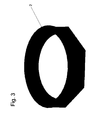
- FIG. 3 shows a ring 2 as a transition ring, which jumps from a rectangular shape in the lower part to a round shape.
- This ring can be placed on a octagonal in the present case lower tower section and offers the aufdin adapter 1 an optimal bearing surface.
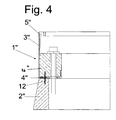
- FIG. 4 shows a section of an adapter 1 "rests on the ring 2".
- the lower leg 4 has an opening which is a connecting element 12 receives.
- the connecting element extends both into a recess in the ring 2 "and into a recess in the concrete ring 1a”.
Landscapes
- Engineering & Computer Science (AREA)
- Architecture (AREA)
- Chemical & Material Sciences (AREA)
- Life Sciences & Earth Sciences (AREA)
- Mechanical Engineering (AREA)
- Combustion & Propulsion (AREA)
- Sustainable Energy (AREA)
- General Engineering & Computer Science (AREA)
- Sustainable Development (AREA)
- Civil Engineering (AREA)
- Structural Engineering (AREA)
- Materials Engineering (AREA)
- Wood Science & Technology (AREA)
- Bridges Or Land Bridges (AREA)
- Wind Motors (AREA)
Description
- Die Erfindung betrifft einen Hybridturm mit einem aus Beton bestehenden rohrförmigen unteren Turmabschnitt und einem aus Stahl bestehenden rohrförmigen oberen Turmabschnitt sowie mit einem zwischen den beiden Turmabschnitten angeordneten Adapter zum Verbinden der beiden Turmabschnitte.
- Die
EP 1 654 460 B1 offenbart einen Hybridturm, bei dem ein Verankerungselemente aufweisender Endbereich des Turmabschnittes aus Metall in den Turmabschnitt aus Beton eingelassen ist. Als Alternative wird hier vorgeschlagen, den Endbereich des Turmabschnittes aus Metall über eine schwierig herzustellende Dichtung auf den Turmabschnitt aus Beton aufzusetzen, und über Spannlitzen die beiden Turmabschnitte gegeneinander zu verspannen. - Durch die
DE 10 2010 039 796 A1 ist ein Hybridturm bekannt geworden, bei dem das Adapterstück einen ringförmigen, im Querschnitt auf dem Kopf stehenden U-förmigen Metallring aufweist. Zur Herstellung des Adapters wird der Metallring, der immerhin einen Durchmesser von 4,50 m aufweisen kann, aufwendig um 180° gedreht, so dass in die dann vorliegende U-Form Beton gegossen werden kann. Dabei müssen neben Hüllrohren für die Spannlitzen zusätzlich noch eine große Anzahl von Ankern gesetzt werden, an denen später der obere Turmabschnitt angeschraubt werden kann. Damit werden die Zug- und Biegekräfte vom oberen Turmabschnitt über die Ankerelemente in den Betonkörper des Adapters eingeleitet und von diesem über den U-förmigen Flansch auf die Zuglitzen übertragen. Neben der sehr aufwendigen Herstellung dieses Adapters ist auch das Einleiten der Kräfte vom oberen Turmabschnitt in den unteren Turmabschnitt problematisch. - Die
EP 2 282 051 offenbart die Verschraubung der Gondel einer Windkraftanlage an der Spitze eines Betonturms. Es wird aber auch ein Adapter aufgezeigt, der vollkommen aus Metall besteht, und der mit der Spitze eines Betonturms verschraubt ist. - Die
DE 20 2006 009 554 U1 offenbart ein Stahladapterelement, welches die Spitze eines Betonturms umgibt und über in die Wandung des Betonturms ragende Verankerungselemente mit dem Betonturm verbunden ist. - Die
DE 102 30 273 B3 offenbart einen Metalladapter, bei dem die Spannlitzen außen am Turm geführt sind, und daher aufwändig durch Verkleidungsbelche geschützt werden müssen. - Die
DE 10 2007 031 065 offenbart einen Hybridturm, bei dem der Adapter aus einem Betonring besteht, der Hüllrohre zur Aufnahme von Ankerbolzen aufweist, mittels derer der obere Turmabschnitt am Adapter befestigt wird. Zusätzlich sind auch hier im Beton eingelassene Spannlitzen, die den unteren Turmabschnitt vorspannen, vorgesehen. Auch hier müssen zusätzlich Hüllrohren für die Spannlitzen weitere Hüllrohre für die Ankerbolzen zunächst justiert und dann eingegossen werden, was die Herstellung des Adapters kompliziert und verteuert. - Die
DE 20 2006 009 554 U1 offenbart einen Adapter mit einem ringförmigen Betonelement, welches von einem Stahlelement umgeben ist. Dabei weist das Stahlelement eine große Anzahl von Verankerungselementen auf, über welche der Betonring mit dem Stahladapterelement verbunden ist. Das Betonelement weist wiederum Hüllrohre für die Spannlitzen auf. Die Zug- und Druckkräfte, die am oberen Turmabschnitt auftreten können, müssen dabei komplett über die Ankerelemente in den Betonring eingeleitet werden. - Der Erfindung liegt die Aufgabe zugrunde, einen Hybridturm so weiterzuentwickeln, dass dessen Adapter günstig hergestellt werden kann und dennoch die am oberen Turmabschnitt entstehenden Zug- bzw. Druckkräfte problemlos auf den unteren Turmabschnitt übertragen werden können.
- Die Aufgabe wird dadurch gelöst, dass der Adapter aus einem im Schnitt annähernd C-förmig ausgestalteten Ring aus Stahl besteht, dass das die Schenkel des C-förmigen Rings verbindende Joch den Außenbereich des Rings bildet, dass der untere Schenkel über den Ring verteilt angeordnete Bohrungen zur Aufnahme der Spannlitzen des unteren Turmabschnitts aufweist, dass der obere Schenkel des C-förmigen Rings ebenfalls über den Ring verteilt angeordnete Bohrungen zur Aufnahme von Befestigungsschrauben für den oberen Turmabschnitt aufweist, dass der untere Schenkel des C-förmigen Rings auf der Krone des unteren Turmabschnitts aufgesetzt ist und dass der Adapter mittels der Spannlitzen in dem unteren Turmabschnitt mit vorgespannt ist.
- Damit werden am, mit dem Adapter fest verbundenen oberen Turmabschnitt entstehende Druckkräfte über das Joch auf den unteren Schenkel und von diesem direkt auf den unteren Turmabschnitt übertragen. Zugkräfte werden über das Joch und den unteren Schenkel in die Spannlitzen eingeleitet, so dass sich das Vorsehen von Ankerbolzen erübrigt. Dadurch ist der Adapter kostengünstig herzustellen und leitet dennoch Zug- oder Druckkräfte, die am oberen Turmabschnitt entstehen, optimal in den unteren Turmabschnitt ein.
- Eine besonders gute Verteilung der insbesondere möglichen auftretenden Zugkräfte ergibt sich, wenn der C-förmige Ring im unteren Bereich mit Beton verfüllt ist und die Bohrungen im unteren Schenkel des C-förmigen Rings von Hüllrohren für die Spannlitzen übergriffen sind.
- Durch den in den Ring eingebrachten Beton lassen sich die Zugkräfte der Spannlitzen sehr gut auf die unteren Schenkel verteilen, so dass die Spann- bzw. Zugkräfte optimaler in den unteren Turmabschnitt eingeleitet werden können.
- Es hat sich bewährt, dass am dem Joch gegenüber liegenden Ende des unteren Schenkels ein aufstehender, kreisförmiger Flansch als verlorene Schalung ausgebildet ist.
- Diese Schalung kann in ihrer Höhe der Höhe des einzubringenden Fertigbetons entsprechen. Sie kann jedoch auch niedriger liegen und als Anschlag für eine weitere aufzusetzende Schalung dienen.
- Es empfiehlt sich, dass sich das umlaufende Joch über die Anbindung des unteren Steges hinaus nach unten erstreckt und einen umlaufenden Sicherungsring zur Lagesicherung des Adapters auf dem unteren Turmabschnitt bildet.
- Dieser Sicherungsring dient insbesondere beim Aufbau des Turms zur Zentrierung des Adapters auf dem unteren Turmabschnitt und zur Lagesicherung des Adapters auf dem unteren Turmabschnitt. Es besteht aber auch die Möglichkeit, dass anstelle eines umlaufenden Sicherungsrings ein mit Unterbrechung versehener Sicherungsring in Form von z. B. drei Nasen, die im Abstand von z. B. 120° angeordnet sind, vorgesehen ist.
- Es hat sich als vorteilhaft erwiesen, dass die Krone des unteren Turmabschnitts mindestens eine Ausnehmung zur Aufnahme des Sicherungsrings aufweist. Damit ist gewährleistet, dass der Turm nach außen eine glatte Oberfläche aufweist und der Sicherungsring nicht vorspringt.
- Zweckmäßig kann aber auch sein, dass der untere Schenkel in dem auf der Krone des unteren Turmabschnittes aufliegenden Bereich mindestens eine Durchbrechung aufweist, und dass die Durchbrechung ein Verbindungselement aufnimmt, wobei die Krone des unteren Turmabschnitts mindestens eine Ausnehmung zur Aufnahme des Verbindungselementes aufweisen sollte. Auch damit ist eine Zentrierung des Adapters auf dem unteren Turmabschnitt möglich.
- Nachahmenswert ist, dass die Krone des unteren Turmabschnitts als ein aus Fertigbeton gefertigter Ring ausgebildet ist. Wird der untere Turmabschnitt z. B. aus einzelnen Segmenten aufgebaut, so ergeben sich senkrechte Fugen auf der Krone des unteren Turmabschnittes. Hier könnte der Adapter, der mit einem unteren Steg auf der mit Fugen versehene Krone aufgelegt werden. Sauberer lässt sich der Adapter jedoch an einen entsprechenden aus Beton gefertigten keine Unterbrechungen aufweisenden Ring aufsetzen.
- Bemerkenswert ist, dass der Ring als Übergang nicht nur von einem runden segmentierten Turmabschnitt auf einen runden geschlossenen Turmabschnitt, sondern auch von einem eckigen segmentierten Turmabschnitt auf einen runden geschlossenen Turmabschnitt ausgebildet sein kann. Damit kann der untere Turmabschnitt sowohl rund als auch mehreckig ausgebildet werden. Es muss lediglich der entsprechend passende Ring verwendet werden.
- Die Erfindung wird anhand einer Zeichnung näher erläutert. Dabei zeigt
- Figur 1
- zeigt einen erfindungsgemäßen Adapter in geschnittener Darstellung,
- Figur 2
- den Ausschnitt eines erfindungsgemäßen Adapters,
- Figur 3
- einen erfindungsgemäßen Übergangsring, und
- Figur 4
- den Ausschnitt eines weiteren erfindungsgemäßen Adapters.
- In der
Figur 1 ist ein Adapter 1 zu erkennen, der auf einem Ring 2, der als Übergangsring dient, aufgesetzt ist. Der Adapter 1 besteht im Wesentlichen aus einem C-förmigen Ring aus Stahl mit einem nach außen weisenden Joch 3, dem unteren Schenkel 4 sowie dem oberen Schenkel 5. Im unteren Schenkel 4 sind Bohrungen 6 angeordnet, die zum Aufnehmen von Spannlitzen 7 dienen. Über die Spannlitzen 7 kann der Adapter 1 mit dem Ring 2 und dem darunter befindlichen Turm aus Beton verspannt werden. Der in dem Adapter 1 vorgesehene Betonring 1 a dient dabei zur Verteilung der Spannkräfte auf den unteren Schenkel 4. - Am oberen Schenkel 5 sind Bohrungen 8 vorgesehen, die zur Aufnahme von Befestigungselementen, z. B. Schraube-Mutter-Verbindungen dienen über welche der obere Turmabschnitt mit dem Adapter 1 verbunden werden kann. Selbstverständlich könne die Bohrungen 8 auch Gewinde aufweisen, die mit den Befestigungsschrauben zusammenwirken.
- Die
Figur 2 zeigt einen Ausschnitt eines Adapters 1', auf dessen oberen Schenkel 5 der Flansch 9 eines unteren Schusses des oberen Turmabschnittes aufliegend dargestellt und über schrauben mit dem Adapter 1' verbunden ist. Am unteren Ende des Joches 3' ist ein Sicherungsring 10 gezeigt, der in entsprechende Ausnehmungen 11 des Ringes 2' eingreift. Damit ist der Adapter 1' in seiner Lage in horizontaler Richtung auf dem Ring 2' gesichert. -
Figur 3 zeigt einen Ring 2 als Übergangsring, der von einer eckigen Form im unteren Bereich auf eine runde Form überspringt. Dieser Ring kann auf einen im vorliegenden Fall achteckigen unteren Turmabschnitt aufgesetzt werden und bietet dem aufzusetzenden Adapter 1 eine optimale Auflagefläche. -
Figur 4 zeigt einen Ausschnitt eines Adapters 1" der auf dem Ring 2" aufliegt. Der untere Schenkel 4" weist eine Durchbrechung auf, die ein Verbindungselement 12 aufnimmt. Das Verbindungselement erstreckt sich sowohl in eine Ausnehmung im Ring 2" als auch in eine Ausnehmung im Betonring 1a". -
- 1
- Adapter
- 2
- Ring
- 3
- Joch
- 4
- unterer Schenkel
- 5
- oberer Schenkel
- 6
- Bohrung
- 7
- Spannlitze
- 8
- Bohrung
- 9
- Flansch
- 10
- Sicherungsring
- 11
- Ausnehmung
- 12
- Verbindungselement
Claims (8)
- Hybridturm, vorzugsweise für Windenergieanlagen, mit einem unteren, aus Betonfertigteilen zusammengesetzten, über Spannlitzen (7) verspannten rohrförmigen unteren Turmabschnitt und einem aus Stahl bestehenden, vorzugsweise aus einzelnen Rohrschüssen zusammengesetzten rohrförmigen oberen Turmabschnitt sowie mit einem zwischen den beiden Turmabschnitten angeordneten, aus einem im Schnitt annähernd C-förmig ausgestalteten Ring aus Stahl bestehenden Adapter (1) zum Verbinden der Turmabschnitte, wobei das die Schenkel (4, 5) des C-förmigen Rings verbindende Joch (3) den Außenbereich des Rings bildet, der untere Schenkel (4) über den Ring verteilt angeordnete Bohrungen (6, 6'..) zur Aufnahme der Spannlitzen (7, 7' ...) des unteren Turmabschnittes aufweist, der obere Schenkel (5) des C-förmigen Rings ebenfalls über den Ring verteilt angeordnete Bohrungen (8, 8' ...) zur Aufnahme von Befestigungsschrauben für den oberen Turmabschnitt aufweist, der untere Schenkel (4) des C-förmigen Rings auf der Krone des unteren Turmabschnittes aufgesetzt ist, der Adapter (1) mittels der Spannlitzen (7, 7' .) in dem unteren Turmabschnitt mit vorgespannt ist, und wobei die Bohrungen (6, 6' ..) im unteren Schenkel (4) des C-förmigen Rings von Hüllrohren für die Spannlitzen übergriffen sind, und der C-förmige Ring im unteren Bereich, die Hüllrohre umgebend, mit Beton gefüllt ist.
- Hybridturm nach Anspruch 1,
dadurch gekennzeichnet,
dass am, dem Joch (3) gegenüberliegenden Ende des unteren Schenkels (4) ein aufstehender, kreisförmiger Flansch als verlorene Schalung ausgebildet ist. - Hybridturm nach Anspruch 1 oder 2,
dadurch gekennzeichnet,
dass sich das umlaufende Joch (3) über die Anbindung des unteren Schenkels (4) hinaus nach unten erstreckt und einen umlaufenden Sicherungsring (10) zur Lagesicherung des Adapters (1) auf dem unteren Turmabschnitt bildet. - Hybridturm nach Anspruch 1 oder 2,
dadurch gekennzeichnet,
dass sich das umlaufende Joch (3) bereichweise über die Anbindung des unteren Schenkels (4) hinaus nach unten erstreckt und einen mit Unterbrechungen versehenen Sicherungsring zur Lagesicherung des Adapters (1) auf dem unteren Turmabschnitt bildet. - Hybridturm nach Anspruch 3 oder 4,
dadurch gekennzeichnet,
dass die Krone des unteren Turmabschnittes mindestens eine Ausnehmung (11) zur Aufnahme des Sicherungsrings (10) aufweist. - Hybridturm nach einem der Ansprüche 1 bis 5,
dadurch gekennzeichnet,
dass der untere Schenkel (4) in dem auf der Krone des unteren Turmabschnittes aufliegenden Bereich mindestens eine Durchbrechung aufweist, dass die Durchbrechung mindestens einer Ausnehmung in der Krone des unteren Turmabschnittes gegenüber angeordnet ist, und dass die Durchbrechung und die Ausnehmung ein Verbindungselement (12) aufnimmt. - Hybridturm nach einem der Ansprüche 1 bis 6,
dadurch gekennzeichnet,
dass die Krone des unteren Turmabschnittes als ein aus Fertigbeton gefertigter Ring (2, 2') ausgebildet ist. - Hybridturm nach Anspruch 7,
dadurch gekennzeichnet,
dass der Ring (2, 2') als Übergang von einem runden oder eckigen segmentierten Turmabschnitt aus Beton auf einen runden geschlossenen Turmabschnitt aus Beton ausgebildet ist.
Priority Applications (1)
| Application Number | Priority Date | Filing Date | Title |
|---|---|---|---|
| PL13701908T PL2807317T3 (pl) | 2012-01-23 | 2013-01-18 | Wieża hybrydowa |
Applications Claiming Priority (2)
| Application Number | Priority Date | Filing Date | Title |
|---|---|---|---|
| DE102012001109A DE102012001109A1 (de) | 2012-01-23 | 2012-01-23 | Hybridturm |
| PCT/EP2013/000146 WO2013110448A1 (de) | 2012-01-23 | 2013-01-18 | Hybridturm |
Publications (2)
| Publication Number | Publication Date |
|---|---|
| EP2807317A1 EP2807317A1 (de) | 2014-12-03 |
| EP2807317B1 true EP2807317B1 (de) | 2015-12-30 |
Family
ID=47630237
Family Applications (1)
| Application Number | Title | Priority Date | Filing Date |
|---|---|---|---|
| EP13701908.9A Active EP2807317B1 (de) | 2012-01-23 | 2013-01-18 | Hybridturm |
Country Status (6)
| Country | Link |
|---|---|
| EP (1) | EP2807317B1 (de) |
| DE (1) | DE102012001109A1 (de) |
| DK (1) | DK2807317T3 (de) |
| ES (1) | ES2562341T3 (de) |
| PL (1) | PL2807317T3 (de) |
| WO (1) | WO2013110448A1 (de) |
Cited By (5)
| Publication number | Priority date | Publication date | Assignee | Title |
|---|---|---|---|---|
| WO2019081491A1 (de) | 2017-10-26 | 2019-05-02 | Wobben Properties Gmbh | Ringförmige konsole zum externen spannen eines turmsegments, externes spannsystem eines hybridturms, turmabschnitt eines hybridturms, hybridturm, windenergieanlage und montageverfahren eines externen spannsystems für einen hybridturm |
| WO2023274477A1 (en) * | 2021-06-30 | 2023-01-05 | Vestas Wind Systems A/S | Transition piece for a hybrid wind turbine tower and method for assembling same |
| US12292029B2 (en) | 2021-07-13 | 2025-05-06 | Ge Vernova Infrastructure Technology Llc | Wind turbine tower structure with transition system between sections thereof |
| DE102024103277A1 (de) * | 2024-02-06 | 2025-08-07 | Max Bögl Wind AG | Adaptervorrichtung zur Verbindung eines unteren Betonturmabschnitts mit einem oberen Stahlturmabschnitt, Adapterstück und Übergangsstück für eine Adaptervorrichtung sowie Turm mit einer Adaptervorrichtung |
| US12529239B2 (en) | 2022-10-31 | 2026-01-20 | Ge Infrastructure Technology Llc | Wind turbine tower structure with stacked tower sections |
Families Citing this family (11)
| Publication number | Priority date | Publication date | Assignee | Title |
|---|---|---|---|---|
| WO2013156632A1 (es) * | 2012-02-28 | 2013-10-24 | Ms Enertech, S.L. | Conexión entre una torre de un aerogenerador y su cimentación |
| FR3011012B1 (fr) * | 2013-09-26 | 2015-11-13 | Pomagalski Sa | Dispositif et procede d'ancrage pour des fondations d'ouvrage de remontee mecanique et pylone de ligne comprenant un tel dispositif |
| US10138648B2 (en) * | 2015-01-09 | 2018-11-27 | Tindall Corporation | Tower and method for assembling tower |
| DE102016203526A1 (de) | 2016-01-20 | 2017-07-20 | Ventur GmbH | Adaptervorrichtung für einen Turm und Verfahren zur Herstellung |
| CN106013618B (zh) * | 2016-07-25 | 2018-01-16 | 佳木斯大学 | 一种建筑用预应力钢筋架 |
| DE102017009984A1 (de) * | 2017-10-26 | 2019-05-02 | Senvion Gmbh | Turm mit konischen Stahladapterelementen |
| DE102019103589A1 (de) * | 2019-02-13 | 2020-08-13 | Wobben Properties Gmbh | Hybrid-Turmabschnitt, Hybrid-Turm für eine Windenergieanlage sowie Herstellungsverfahren |
| DE102020200600A1 (de) | 2020-01-20 | 2021-07-22 | KTW Umweltschutztechnik GmbH | Verfahren zur Instandsetzung einer Stahlbeton-Bauteil-Anordnung |
| CN115992801A (zh) * | 2021-10-18 | 2023-04-21 | 上海风领新能源有限公司 | 钢-混凝土混合式塔筒及其施工工艺 |
| DK181357B1 (en) * | 2021-12-07 | 2023-08-29 | Stiesdal Offshore As | An offshore wind turbine installation with a concrete-cast transition piece between the wind turbine tower and its support |
| DE102024127388A1 (de) | 2024-09-23 | 2026-03-26 | Max Bögl Wind AG | Adapterstück zur Verbindung eines unteren, ringförmigen Betonturmabschnitts mit einem oberen, ringförmigen Stahlturmabschnitt sowie Turm mit einem Adapterstück |
Family Cites Families (8)
| Publication number | Priority date | Publication date | Assignee | Title |
|---|---|---|---|---|
| DE10230273B3 (de) * | 2002-07-05 | 2004-02-12 | Institut für Fertigteiltechnik und Fertigbau Weimar e.V. | Turm einer Windkraftanlage mit einem unteren Teil aus Spannbeton und einem aufgesetzten Stahlrohr |
| EP1654460B1 (de) * | 2003-08-09 | 2007-02-14 | General Electric Company | Turmfundament, insbesondere für eine windenergieturbine |
| DE202006009554U1 (de) | 2006-06-16 | 2006-11-02 | Oevermann Gmbh & Co. Kg | Hybrides Turmbauwerk |
| EP1947328B1 (de) * | 2007-01-18 | 2018-10-24 | GE Renewable Technologies | Verbindungsvorrichtung für hybride Windenergieanlagentürme |
| DE102007031065B4 (de) | 2007-06-28 | 2011-05-05 | Nordex Energy Gmbh | Windenergieanlagenturm |
| ES2378199B1 (es) * | 2009-06-24 | 2013-06-05 | Acciona Windpower S.A. | Sistema de unión de una góndola con la torre de hormigón de un aerogenerador. |
| DE102010039796A1 (de) | 2010-06-14 | 2011-12-15 | Max Bögl Bauunternehmung GmbH & Co. KG | Turm mit einem Adapterstück sowie Verfahren zur Herstellung eines Turms mit einem Adapterstück |
| US20110138704A1 (en) * | 2010-06-30 | 2011-06-16 | General Electric Company | Tower with tensioning cables |
-
2012
- 2012-01-23 DE DE102012001109A patent/DE102012001109A1/de not_active Ceased
-
2013
- 2013-01-18 EP EP13701908.9A patent/EP2807317B1/de active Active
- 2013-01-18 WO PCT/EP2013/000146 patent/WO2013110448A1/de not_active Ceased
- 2013-01-18 ES ES13701908.9T patent/ES2562341T3/es active Active
- 2013-01-18 PL PL13701908T patent/PL2807317T3/pl unknown
- 2013-01-18 DK DK13701908.9T patent/DK2807317T3/da active
Cited By (6)
| Publication number | Priority date | Publication date | Assignee | Title |
|---|---|---|---|---|
| WO2019081491A1 (de) | 2017-10-26 | 2019-05-02 | Wobben Properties Gmbh | Ringförmige konsole zum externen spannen eines turmsegments, externes spannsystem eines hybridturms, turmabschnitt eines hybridturms, hybridturm, windenergieanlage und montageverfahren eines externen spannsystems für einen hybridturm |
| US11136780B2 (en) | 2017-10-26 | 2021-10-05 | Wobben Properties Gmbh | Annular bracket for externally loading a tower segment, external loading system of a hybrid tower, tower section of a hybrid tower, hybrid tower, wind turbine, and assembly method of an external loading system for a hybrid tower |
| WO2023274477A1 (en) * | 2021-06-30 | 2023-01-05 | Vestas Wind Systems A/S | Transition piece for a hybrid wind turbine tower and method for assembling same |
| US12292029B2 (en) | 2021-07-13 | 2025-05-06 | Ge Vernova Infrastructure Technology Llc | Wind turbine tower structure with transition system between sections thereof |
| US12529239B2 (en) | 2022-10-31 | 2026-01-20 | Ge Infrastructure Technology Llc | Wind turbine tower structure with stacked tower sections |
| DE102024103277A1 (de) * | 2024-02-06 | 2025-08-07 | Max Bögl Wind AG | Adaptervorrichtung zur Verbindung eines unteren Betonturmabschnitts mit einem oberen Stahlturmabschnitt, Adapterstück und Übergangsstück für eine Adaptervorrichtung sowie Turm mit einer Adaptervorrichtung |
Also Published As
| Publication number | Publication date |
|---|---|
| DE102012001109A1 (de) | 2013-07-25 |
| WO2013110448A1 (de) | 2013-08-01 |
| ES2562341T3 (es) | 2016-03-03 |
| DK2807317T3 (da) | 2016-03-07 |
| PL2807317T3 (pl) | 2016-06-30 |
| EP2807317A1 (de) | 2014-12-03 |
Similar Documents
| Publication | Publication Date | Title |
|---|---|---|
| WO2013110448A1 (de) | Hybridturm | |
| DE102009016893B4 (de) | Verankerungsbauteil für einen Windenergieanlagenturm | |
| EP2009202B1 (de) | Windenergieanlagenturm | |
| EP2729621B1 (de) | Anordnung zum abstützen eines zugglieds, insbesondere eines schrägseils, quer zu seiner längserstreckungsrichtung | |
| EP1262614B2 (de) | Windkraftanlage | |
| EP2744955B1 (de) | Vorrichtung und verfahren für den übergang zwischen einem aufgehenden turmabschnitt und einem vorgespannten betonturmabschnitt | |
| WO2020012345A1 (de) | Fundament für ein windkraftwerk | |
| WO2002004766A2 (de) | Turm aus spannbeton-fertigteilen | |
| EP3662122A1 (de) | Fundament für ein bauwerk | |
| DE102016203494A1 (de) | Adaptervorrichtung für einen Turm und Verfahren zur Herstellung | |
| DE69314240T2 (de) | Entfernbarer Erdanker | |
| EP1609912A1 (de) | Ausbildung eines korrosionsgeschützten Zugglieds im Bereich einer an einer Abstützung angeordneten Umlenkstelle, insbesondere eines Schrägseils am Pylon einer Schrägseilbrücke | |
| DE102019112608A1 (de) | Betonfertigteilplatte und Verbundbauteil mit einer Betonfertigteilplatte | |
| EP1609911A1 (de) | Ausbildung eines korrosionsgeschützten Zugglieds im Bereich seines Eintritts in ein Bauwerk, insbesondere eines Schrägseils am Pylon einer Schrägseilbrücke | |
| DE29809541U1 (de) | Vorrichtung zum Herstellen von hohen, hohlen, turmartigen Bauwerken von zweihundert Metern Höhe und mehr, insbesondere von Türmen für Windkraftanlagen | |
| EP3891386A1 (de) | Verfahren zum vorspannen eines turms einer windenergieanlage | |
| DE202006009554U1 (de) | Hybrides Turmbauwerk | |
| EP4613954A2 (de) | Gewindehülse zur verankerung von bauelementen in einem betonbauwerk, und ein distanzrohr | |
| DE102009016892A1 (de) | Vorrichtung zur lösbaren Verbindung eines Turmabschnitts mit einem Fundament einer Windenergieanlage | |
| EP0181898A1 (de) | Bewehrungselement aus stahlteilen für spannbetonkonstruktionen und spannbeton-fertigteilen | |
| DE19901510A1 (de) | Fundament für oberirdische Türme | |
| EP1338724B1 (de) | Verfahren zur Errichtung eines Bauwerks mit einer umfangsgeschlossenen Betonwand | |
| WO2002012657A1 (de) | Baumodul zum herstellen von brücken, gebäuden und türmen, zum beispiel für windkraftanlagen | |
| EP1079040B1 (de) | Korrosionsgeschütztes freies Zugglied, vornehmlich externes Spannglied für Spannbeton | |
| DE20014322U1 (de) | Abstützung eines freien Zugglieds, insbesondere eines Schrägseils für eine Schrägseilbrücke |
Legal Events
| Date | Code | Title | Description |
|---|---|---|---|
| PUAI | Public reference made under article 153(3) epc to a published international application that has entered the european phase |
Free format text: ORIGINAL CODE: 0009012 |
|
| 17P | Request for examination filed |
Effective date: 20140704 |
|
| AK | Designated contracting states |
Kind code of ref document: A1 Designated state(s): AL AT BE BG CH CY CZ DE DK EE ES FI FR GB GR HR HU IE IS IT LI LT LU LV MC MK MT NL NO PL PT RO RS SE SI SK SM TR |
|
| DAX | Request for extension of the european patent (deleted) | ||
| GRAP | Despatch of communication of intention to grant a patent |
Free format text: ORIGINAL CODE: EPIDOSNIGR1 |
|
| INTG | Intention to grant announced |
Effective date: 20150623 |
|
| GRAS | Grant fee paid |
Free format text: ORIGINAL CODE: EPIDOSNIGR3 |
|
| GRAA | (expected) grant |
Free format text: ORIGINAL CODE: 0009210 |
|
| AK | Designated contracting states |
Kind code of ref document: B1 Designated state(s): AL AT BE BG CH CY CZ DE DK EE ES FI FR GB GR HR HU IE IS IT LI LT LU LV MC MK MT NL NO PL PT RO RS SE SI SK SM TR |
|
| REG | Reference to a national code |
Ref country code: GB Ref legal event code: FG4D Free format text: NOT ENGLISH |
|
| REG | Reference to a national code |
Ref country code: CH Ref legal event code: EP |
|
| REG | Reference to a national code |
Ref country code: AT Ref legal event code: REF Ref document number: 767575 Country of ref document: AT Kind code of ref document: T Effective date: 20160115 |
|
| REG | Reference to a national code |
Ref country code: FR Ref legal event code: PLFP Year of fee payment: 4 |
|
| REG | Reference to a national code |
Ref country code: IE Ref legal event code: FG4D Free format text: LANGUAGE OF EP DOCUMENT: GERMAN |
|
| REG | Reference to a national code |
Ref country code: DE Ref legal event code: R096 Ref document number: 502013001705 Country of ref document: DE |
|
| REG | Reference to a national code |
Ref country code: RO Ref legal event code: EPE |
|
| REG | Reference to a national code |
Ref country code: ES Ref legal event code: FG2A Ref document number: 2562341 Country of ref document: ES Kind code of ref document: T3 Effective date: 20160303 |
|
| REG | Reference to a national code |
Ref country code: DK Ref legal event code: T3 Effective date: 20160304 |
|
| REG | Reference to a national code |
Ref country code: SE Ref legal event code: TRGR |
|
| REG | Reference to a national code |
Ref country code: NL Ref legal event code: FP |
|
| REG | Reference to a national code |
Ref country code: LT Ref legal event code: MG4D |
|
| PG25 | Lapsed in a contracting state [announced via postgrant information from national office to epo] |
Ref country code: LT Free format text: LAPSE BECAUSE OF FAILURE TO SUBMIT A TRANSLATION OF THE DESCRIPTION OR TO PAY THE FEE WITHIN THE PRESCRIBED TIME-LIMIT Effective date: 20151230 Ref country code: HR Free format text: LAPSE BECAUSE OF FAILURE TO SUBMIT A TRANSLATION OF THE DESCRIPTION OR TO PAY THE FEE WITHIN THE PRESCRIBED TIME-LIMIT Effective date: 20151230 Ref country code: NO Free format text: LAPSE BECAUSE OF FAILURE TO SUBMIT A TRANSLATION OF THE DESCRIPTION OR TO PAY THE FEE WITHIN THE PRESCRIBED TIME-LIMIT Effective date: 20160330 |
|
| PG25 | Lapsed in a contracting state [announced via postgrant information from national office to epo] |
Ref country code: RS Free format text: LAPSE BECAUSE OF FAILURE TO SUBMIT A TRANSLATION OF THE DESCRIPTION OR TO PAY THE FEE WITHIN THE PRESCRIBED TIME-LIMIT Effective date: 20151230 Ref country code: LV Free format text: LAPSE BECAUSE OF FAILURE TO SUBMIT A TRANSLATION OF THE DESCRIPTION OR TO PAY THE FEE WITHIN THE PRESCRIBED TIME-LIMIT Effective date: 20151230 |
|
| REG | Reference to a national code |
Ref country code: GR Ref legal event code: EP Ref document number: 20160400289 Country of ref document: GR Effective date: 20160414 |
|
| PG25 | Lapsed in a contracting state [announced via postgrant information from national office to epo] |
Ref country code: LU Free format text: LAPSE BECAUSE OF FAILURE TO SUBMIT A TRANSLATION OF THE DESCRIPTION OR TO PAY THE FEE WITHIN THE PRESCRIBED TIME-LIMIT Effective date: 20160118 Ref country code: IS Free format text: LAPSE BECAUSE OF FAILURE TO SUBMIT A TRANSLATION OF THE DESCRIPTION OR TO PAY THE FEE WITHIN THE PRESCRIBED TIME-LIMIT Effective date: 20160430 Ref country code: EE Free format text: LAPSE BECAUSE OF FAILURE TO SUBMIT A TRANSLATION OF THE DESCRIPTION OR TO PAY THE FEE WITHIN THE PRESCRIBED TIME-LIMIT Effective date: 20151230 Ref country code: SK Free format text: LAPSE BECAUSE OF FAILURE TO SUBMIT A TRANSLATION OF THE DESCRIPTION OR TO PAY THE FEE WITHIN THE PRESCRIBED TIME-LIMIT Effective date: 20151230 Ref country code: SM Free format text: LAPSE BECAUSE OF FAILURE TO SUBMIT A TRANSLATION OF THE DESCRIPTION OR TO PAY THE FEE WITHIN THE PRESCRIBED TIME-LIMIT Effective date: 20151230 Ref country code: PT Free format text: LAPSE BECAUSE OF FAILURE TO SUBMIT A TRANSLATION OF THE DESCRIPTION OR TO PAY THE FEE WITHIN THE PRESCRIBED TIME-LIMIT Effective date: 20160502 |
|
| REG | Reference to a national code |
Ref country code: CH Ref legal event code: PL |
|
| PG25 | Lapsed in a contracting state [announced via postgrant information from national office to epo] |
Ref country code: MC Free format text: LAPSE BECAUSE OF FAILURE TO SUBMIT A TRANSLATION OF THE DESCRIPTION OR TO PAY THE FEE WITHIN THE PRESCRIBED TIME-LIMIT Effective date: 20151230 |
|
| REG | Reference to a national code |
Ref country code: DE Ref legal event code: R097 Ref document number: 502013001705 Country of ref document: DE |
|
| PG25 | Lapsed in a contracting state [announced via postgrant information from national office to epo] |
Ref country code: CH Free format text: LAPSE BECAUSE OF NON-PAYMENT OF DUE FEES Effective date: 20160131 Ref country code: LI Free format text: LAPSE BECAUSE OF NON-PAYMENT OF DUE FEES Effective date: 20160131 |
|
| REG | Reference to a national code |
Ref country code: IE Ref legal event code: MM4A |
|
| PLBE | No opposition filed within time limit |
Free format text: ORIGINAL CODE: 0009261 |
|
| STAA | Information on the status of an ep patent application or granted ep patent |
Free format text: STATUS: NO OPPOSITION FILED WITHIN TIME LIMIT |
|
| 26N | No opposition filed |
Effective date: 20161003 |
|
| REG | Reference to a national code |
Ref country code: FR Ref legal event code: PLFP Year of fee payment: 5 |
|
| PG25 | Lapsed in a contracting state [announced via postgrant information from national office to epo] |
Ref country code: IE Free format text: LAPSE BECAUSE OF NON-PAYMENT OF DUE FEES Effective date: 20160118 |
|
| PG25 | Lapsed in a contracting state [announced via postgrant information from national office to epo] |
Ref country code: SI Free format text: LAPSE BECAUSE OF FAILURE TO SUBMIT A TRANSLATION OF THE DESCRIPTION OR TO PAY THE FEE WITHIN THE PRESCRIBED TIME-LIMIT Effective date: 20151230 |
|
| PG25 | Lapsed in a contracting state [announced via postgrant information from national office to epo] |
Ref country code: MT Free format text: LAPSE BECAUSE OF FAILURE TO SUBMIT A TRANSLATION OF THE DESCRIPTION OR TO PAY THE FEE WITHIN THE PRESCRIBED TIME-LIMIT Effective date: 20151230 |
|
| REG | Reference to a national code |
Ref country code: FR Ref legal event code: PLFP Year of fee payment: 6 |
|
| PG25 | Lapsed in a contracting state [announced via postgrant information from national office to epo] |
Ref country code: HU Free format text: LAPSE BECAUSE OF FAILURE TO SUBMIT A TRANSLATION OF THE DESCRIPTION OR TO PAY THE FEE WITHIN THE PRESCRIBED TIME-LIMIT; INVALID AB INITIO Effective date: 20130118 |
|
| PG25 | Lapsed in a contracting state [announced via postgrant information from national office to epo] |
Ref country code: CY Free format text: LAPSE BECAUSE OF FAILURE TO SUBMIT A TRANSLATION OF THE DESCRIPTION OR TO PAY THE FEE WITHIN THE PRESCRIBED TIME-LIMIT Effective date: 20151230 |
|
| PG25 | Lapsed in a contracting state [announced via postgrant information from national office to epo] |
Ref country code: AL Free format text: LAPSE BECAUSE OF FAILURE TO SUBMIT A TRANSLATION OF THE DESCRIPTION OR TO PAY THE FEE WITHIN THE PRESCRIBED TIME-LIMIT Effective date: 20151230 |
|
| PGFP | Annual fee paid to national office [announced via postgrant information from national office to epo] |
Ref country code: GB Payment date: 20220119 Year of fee payment: 10 Ref country code: FI Payment date: 20220120 Year of fee payment: 10 Ref country code: DK Payment date: 20220121 Year of fee payment: 10 Ref country code: BG Payment date: 20220119 Year of fee payment: 10 Ref country code: AT Payment date: 20220120 Year of fee payment: 10 |
|
| PGFP | Annual fee paid to national office [announced via postgrant information from national office to epo] |
Ref country code: TR Payment date: 20220114 Year of fee payment: 10 Ref country code: SE Payment date: 20220119 Year of fee payment: 10 Ref country code: RO Payment date: 20220114 Year of fee payment: 10 Ref country code: PL Payment date: 20220114 Year of fee payment: 10 Ref country code: NL Payment date: 20220119 Year of fee payment: 10 Ref country code: MK Payment date: 20220114 Year of fee payment: 10 Ref country code: IT Payment date: 20220120 Year of fee payment: 10 Ref country code: GR Payment date: 20220120 Year of fee payment: 10 Ref country code: FR Payment date: 20220119 Year of fee payment: 10 Ref country code: ES Payment date: 20220325 Year of fee payment: 10 Ref country code: CZ Payment date: 20220117 Year of fee payment: 10 Ref country code: BE Payment date: 20220119 Year of fee payment: 10 |
|
| P01 | Opt-out of the competence of the unified patent court (upc) registered |
Effective date: 20230517 |
|
| REG | Reference to a national code |
Ref country code: DK Ref legal event code: EBP Effective date: 20230131 |
|
| REG | Reference to a national code |
Ref country code: SE Ref legal event code: EUG |
|
| REG | Reference to a national code |
Ref country code: NL Ref legal event code: MM Effective date: 20230201 |
|
| REG | Reference to a national code |
Ref country code: AT Ref legal event code: MM01 Ref document number: 767575 Country of ref document: AT Kind code of ref document: T Effective date: 20230118 |
|
| GBPC | Gb: european patent ceased through non-payment of renewal fee |
Effective date: 20230118 |
|
| REG | Reference to a national code |
Ref country code: BE Ref legal event code: MM Effective date: 20230131 |
|
| PG25 | Lapsed in a contracting state [announced via postgrant information from national office to epo] |
Ref country code: SE Free format text: LAPSE BECAUSE OF NON-PAYMENT OF DUE FEES Effective date: 20230119 Ref country code: RO Free format text: LAPSE BECAUSE OF NON-PAYMENT OF DUE FEES Effective date: 20230118 Ref country code: NL Free format text: LAPSE BECAUSE OF NON-PAYMENT OF DUE FEES Effective date: 20230201 Ref country code: GB Free format text: LAPSE BECAUSE OF NON-PAYMENT OF DUE FEES Effective date: 20230118 Ref country code: FI Free format text: LAPSE BECAUSE OF NON-PAYMENT OF DUE FEES Effective date: 20230118 Ref country code: CZ Free format text: LAPSE BECAUSE OF NON-PAYMENT OF DUE FEES Effective date: 20230118 Ref country code: AT Free format text: LAPSE BECAUSE OF NON-PAYMENT OF DUE FEES Effective date: 20230118 |
|
| PG25 | Lapsed in a contracting state [announced via postgrant information from national office to epo] |
Ref country code: GR Free format text: LAPSE BECAUSE OF NON-PAYMENT OF DUE FEES Effective date: 20230804 Ref country code: FR Free format text: LAPSE BECAUSE OF NON-PAYMENT OF DUE FEES Effective date: 20230131 Ref country code: BE Free format text: LAPSE BECAUSE OF NON-PAYMENT OF DUE FEES Effective date: 20230131 |
|
| PG25 | Lapsed in a contracting state [announced via postgrant information from national office to epo] |
Ref country code: IT Free format text: LAPSE BECAUSE OF NON-PAYMENT OF DUE FEES Effective date: 20230118 Ref country code: DK Free format text: LAPSE BECAUSE OF NON-PAYMENT OF DUE FEES Effective date: 20230131 |
|
| REG | Reference to a national code |
Ref country code: ES Ref legal event code: FD2A Effective date: 20240402 |
|
| PG25 | Lapsed in a contracting state [announced via postgrant information from national office to epo] |
Ref country code: ES Free format text: LAPSE BECAUSE OF NON-PAYMENT OF DUE FEES Effective date: 20230119 |
|
| PG25 | Lapsed in a contracting state [announced via postgrant information from national office to epo] |
Ref country code: ES Free format text: LAPSE BECAUSE OF NON-PAYMENT OF DUE FEES Effective date: 20230119 |
|
| PG25 | Lapsed in a contracting state [announced via postgrant information from national office to epo] |
Ref country code: PL Free format text: LAPSE BECAUSE OF NON-PAYMENT OF DUE FEES Effective date: 20230118 |
|
| PG25 | Lapsed in a contracting state [announced via postgrant information from national office to epo] |
Ref country code: BG Free format text: LAPSE BECAUSE OF NON-PAYMENT OF DUE FEES Effective date: 20230118 |
|
| PG25 | Lapsed in a contracting state [announced via postgrant information from national office to epo] |
Ref country code: BG Free format text: LAPSE BECAUSE OF NON-PAYMENT OF DUE FEES Effective date: 20230118 |
|
| REG | Reference to a national code |
Ref country code: DE Ref legal event code: R082 Ref document number: 502013001705 Country of ref document: DE Representative=s name: KLUEPPEL, WALTER, DIPL.-ING., DE Ref country code: DE Ref legal event code: R081 Ref document number: 502013001705 Country of ref document: DE Owner name: FUCHS FERTIGTEILWERKE SIEGEN GMBH, DE Free format text: FORMER OWNER: DROESSLER GMBH UMWELTTECHNIK, 57080 SIEGEN, DE |
|
| PGFP | Annual fee paid to national office [announced via postgrant information from national office to epo] |
Ref country code: DE Payment date: 20260121 Year of fee payment: 14 |