EP2807096B1 - System und verfahren zur überwachung des zustands eines förderbandes - Google Patents
System und verfahren zur überwachung des zustands eines förderbandes Download PDFInfo
- Publication number
- EP2807096B1 EP2807096B1 EP12700972.8A EP12700972A EP2807096B1 EP 2807096 B1 EP2807096 B1 EP 2807096B1 EP 12700972 A EP12700972 A EP 12700972A EP 2807096 B1 EP2807096 B1 EP 2807096B1
- Authority
- EP
- European Patent Office
- Prior art keywords
- conveyor belt
- condition
- signal
- processing unit
- sensor
- Prior art date
- Legal status (The legal status is an assumption and is not a legal conclusion. Google has not performed a legal analysis and makes no representation as to the accuracy of the status listed.)
- Active
Links
Images


Classifications
-
- B—PERFORMING OPERATIONS; TRANSPORTING
- B65—CONVEYING; PACKING; STORING; HANDLING THIN OR FILAMENTARY MATERIAL
- B65G—TRANSPORT OR STORAGE DEVICES, e.g. CONVEYORS FOR LOADING OR TIPPING, SHOP CONVEYOR SYSTEMS OR PNEUMATIC TUBE CONVEYORS
- B65G43/00—Control devices, e.g. for safety, warning or fault-correcting
- B65G43/02—Control devices, e.g. for safety, warning or fault-correcting detecting dangerous physical condition of load carriers, e.g. for interrupting the drive in the event of overheating
Definitions
- the invention relates to a system and a method for monitoring the condition of a conveyor belt according to the preamble of claims 1 and 13 respectively, where the conveyor belt is arranged to rotate about at least a drive pulley and an idler pulley, an electrical motor is arranged to drive the drive pulley and the system comprises at least one sensor unit.
- Belt conveyor systems are used for bulk material or good transportation in different industries and especially in mining.
- the essential part of a belt conveyor system is the conveyor belt which carries the bulk material, such as coal or lignite, or the goods, and transports them continuously over a long distance from one point to another.
- the belt conveyor systems are subject to harsh environmental conditions which cause wearing of the conveyor belt material and result in damages of the belt, such as cracks and rips. Such damages do not only reduce the lifetime of the conveyor belt but may also lead to an unexpected stop of production if not recognized in time to organize for the maintenance of the belt. Because the conveyor belt is continuously moving under normal operating conditions, it is difficult to monitor the condition of the belt and to measure the state of wear and tear or to detect any damages.
- US 6,047,814 discloses a method for monitoring a continuous moving belt, where two transponders are disposed in or on the belt in the connecting region of the belt, where the connecting region is the region in which the ends of the conveyor belt are connected to each other.
- the transponders each transmit a signal to an external transmitter/receiver unit when passing through an operating region of the external transmitter/receiver unit.
- the transponders are integrated circuits which are conductively connected to a coil.
- the transponders are positioned within the connecting region due to the fact that it was recognized that the connecting region is a weak location in the conveyor belt which have to be monitored for signs of loosening.
- a device for the non-destructive detection of an operating state of elastic components such as conveyor belts made of rubber.
- elastomer encoders are embedded in two so called measuring regions, where the first measuring region has a different timely behavior of its tensile strength compared to the second measuring region.
- the device further has a sensor station by means of which magnetic fields originating from the elastomer encoders can be detected when passing the sensor station, where the magnetic fields are then processed into information about the expansion or elongation of the corresponding measuring region.
- the US 4,436,198 describes a conveyor belt rip detection system, where a plurality of antennas is embedded in the belt generally transversely to the travel direction of the belt and where the respective antennas pass in capacitive coupling relation with a transmitter/receiver at a rip detector station and send an electrical signal to the transmitter/receiver.
- a rip or crack in the conveyor belt material will be recognized through the corresponding antenna being broken and not sending any signal to the transmitter/receiver.
- DE 31 11 219 A1 is disclosing a system and a method for monitoring the condition of a conveyor belt according to the preamble of claims 1 and 13 respectively; it discloses a device for preventing one or more conveyor belts in a belt-conveyor system from being slit longitudinally by objects which can be jammed at the charging points and/or transfer points for the goods to be conveyed.
- the device comprises in each case a monitoring member for each charging point and/or transfer point, which member transfers to a comparison unit characteristic values for the movement of the goods to be conveyed, e.g. the conveying rate, or for the loading of the drive, e.g. the motor power.
- Said comparison unit compares this value with a previously received characteristic value and, in the event of a deviation which exceeds a predetermined deviation, gives a switch-off command to the associated drive motor.
- the at least one sensor unit is arranged to determine at least one sensor signal representing at least one operating variable of the electrical motor driving the drive pulley, and at least one data processing unit is arranged to
- the method according to the invention contains the method steps performed by the at least one sensor unit and by the data processing unit.
- the splice region is the region in which the ends of the conveyor belt are connected to each other to form a joint or junction.
- the joint is made by lapping or butting, straight or on a bias, and it is held together through vulcanization or mechanical means.
- the splice region may also be called joint region or connecting region.
- the invention is based on the recognition of the fact that the above named irregularities can be observed permanently in measurement signals taken at a belt conveyor system, since the splice region has other mechanical characteristics than the rest of the conveyor belt due to being thicker. As a result, the splice region applies different forces to the drive pulley and/or the idler pulley than the rest of the belt.
- the shape and/or the frequency of the irregularities start to differ from those irregularities occurring with an intact conveyor belt. According to the invention, these differences are detected by the data processing unit and a corresponding monitoring output signal is displayed and/or stored and/or sent to a decision making unit for deciding whether maintenance or exchanging of the conveyor belt becomes necessary.
- a system and method are proposed for a non-invasive monitoring of the state of the conveyor belt, which is easily implemented in an existing conveyor belt system. Since commonly available sensor information of the electrical motor is used, the effort to integrate measuring parts in the belt material and to arrange a corresponding receiving device or an external sensor device at the belt conveyor system is avoided.
- the at least one operating variable of the electrical motor is one of a voltage, a current, a rotational speed, an acceleration, a torque or a force signal
- the at least one sensor unit is a current and/or voltage sensor, a speed encoder, a torque transducer, for example a strain gauge, or a force transducer.
- the at least one data signal may represent an amplitude over time or a frequency spectrum, where the time dependency of the frequency spectrum is achieved by repeatedly deriving the spectrum for subsequent points in time from the corresponding sensor signal.
- the at least one data processing unit may either be a single stand-alone processing device or it may be two or more processing devices interoperating with each other, where the two or more processing devices may be integrated in one and the same computer unit or in separate units.
- one or more of the processing devices are integrated parts of an electrical converter, in particular a frequency converter, where the converter is connected to the electrical motor and is arranged to supply it with a current and/or voltage.
- Most electrical motors are nowadays supplied and controlled via a corresponding electrical converter, where the controlling is performed in a processing device belonging to the converter.
- This processing device is supplied with one or multiple sensor signals representing one or multiple operating variables of the motor, respectively, and it derives from these sensor signals the corresponding time dependent data signals, which are needed for the control functions, such as current, voltage, torque and/or speed. Accordingly, it is especially advantageous to apply the proposed monitoring method in those cases where the driving motor of the conveyor belt is supplied via an electrical converter, since the required data signals are already present and need only be further processed with respect to the irregularities.
- the at least one data processing unit may be arranged to determine whether the condition of the conveyor belt has changed or not by comparing the shape and/or the frequency of the irregularities either with a corresponding threshold or with the shape and frequency of a reference irregularity, where the reference irregularity advantageously represents an intact and healthy conveyor belt.
- a model-based state observer may be used for determining the state or condition of the conveyor belt.
- the shape of the irregularities may be determined from a change in the amplitude height and/or from a change in the width of peaks of the irregularities.
- the at least one sensor unit is arranged to determine a first sensor signal and a second sensor signal representing a first and a second operating variable of the electrical motor, respectively, and where the at least one data processing unit is arranged to derive corresponding first and second data signals and to detect irregularities either in the first signal if the corresponding operating variable of the electrical motor is controlled to follow a first reference variable or in the second signal if the corresponding operating variable of the electrical motor is controlled to follow a second reference variable.
- the first sensor signal may for example be a speed signal and the second sensor signal may be a torque signal.
- the speed and torque are mechanical operating variables of the electrical motor, which can both be controlled.
- a control algorithm in general reacts to any unwanted irregularities and tries to reduce them, the effects of the splice region may become less visible in the data signals corresponding to a controlled variable compared to the data signals of an uncontrolled variable. Therefore, it is suggested to look for the irregularities rather in the signal of an uncontrolled variable, i.e. to observe the irregularities in the speed signal if the torque of the motor is controlled and vice versa.
- the system and method for monitoring the condition of the conveyor belt may be extended by in addition taking into account a vibration data signal, which may be derived in the form of an acceleration or speed sensor signal delivered by a vibration measurement unit, where the vibration measuring unit measures the vibration of a mechanical part attached to the electrical motor, such as the motor drum, a gear or a bearing.
- a vibration data signal which may be derived in the form of an acceleration or speed sensor signal delivered by a vibration measurement unit, where the vibration measuring unit measures the vibration of a mechanical part attached to the electrical motor, such as the motor drum, a gear or a bearing.
- the conveyor belt is arranged to rotate further about a take-up pulley and the at least one data processing unit is arranged to determine a change in the condition of the conveyor belt by further taking into account a displacement sensor signal delivered by a distance measurement unit measuring the displacement of the take-up pulley.
- a belt tension sensor signal delivered by a force measurement unit and/or an image sensor signal delivered by a radiation sensor observing the conveyor belt may be taken into account.
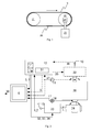
- Fig. 1 shows a simple conveyor belt 9 which rotates about a drive pulley 20 and an idler pulley 21.
- the conveyor belt is comparatively short having a length of about 18 meters.
- the conveyor belt has one splice region 26, where the splice region is the region where the ends of the belt material overlap and are fastened with each other. Other, and in particular longer, conveyor belts may have more than just one splice region.
- the splice region of the conveyor belt of Fig. 1 is approximately 4 meters long.
- An electrical motor 23 drives the drive pulley, where a gear 24 is installed between motor 23 and drive pulley 21.
- Figure 4 shows the measurement signal of a force transducer taken at the cylinder of idler pulley 21 of Fig. 1 . Apart from the force signal which is depicted as a solid line in the upper region of the diagram, Fig. 4 also shows the number of belt cycles, i.e. the number of revolutions of the belt. The corresponding line is the dotted line in the lower region of the diagram. As can be seen, the 111 th and the 112 th cycle are depicted in their full length.
- the conveyor belt 9 of Figs. 1 and 4 is intact, without any rips or cracks.
- the operating state shown in Fig. 4 is a linear acceleration of the conveyor belt. Accordingly, the cylinder force should simply show a linear increase.
- two irregularities in the form of peaks 27 occur in the force signal during the 111 th cycle at points in time T1 and T2, and two irregularities in the form of peaks 28 occur during the 112 th cycle at points in time T3 and T4.
- these peaks are no exceptions but occur frequently and coincide with the passing of the splice region at the drive pulley 20 and the idler pulley 21, respectively.
- the first of the two peaks 27 and 28, respectively always occurs when the splice region 26 passes the drive pulley 20, and the second of the two peaks 27 and 28, respectively, indicates the passing of the idler pulley 21.
- Figs. 5 to 7 the results of long time tests of the conveyor belt 9 of Fig. 1 are depicted.
- Fig. 5 shows a series of frequency spectra of the rotational speed n of motor 23 which were generated at subsequent points in time t.
- each frequency spectrum was calculated about 30 minutes after the previous one, so that Fig. 5 covers an overall time period of about two days.
- the amplitude and frequency ranges are both adjusted so that the dominant amplitude of the actual motor frequency is not visible.
- a first row of considerable amplitudes belongs to the rotational frequency f1 of conveyor belt 9, and a second row of even higher amplitudes belongs to the corresponding first harmonic f2, i.e. to the double rotational frequency of conveyor belt 9.
- Fig. 5 shows a series of frequency spectra of the rotational speed n of motor 23 which were generated at subsequent points in time t.
- each frequency spectrum was calculated about 30 minutes after the previous one, so that Fig. 5 covers an overall time period of about two days.
- the rotational frequency f1 corresponds to the time difference between the respective first of the two peaks 27 and 28, i.e. it is defined by the time period the conveyor belt takes to pass one of the pulleys 20 or 21, respectively. That the rotational frequency f1 is so clearly visible in the frequency spectrum is due to the above described effect of the splice region.
- Fig. 6 differs from Fig. 5 only in that the torque M of motor 23 is shown instead of rotational speed n.
- the amplitudes at the rotational frequency f1 of conveyor belt 9 and at its first harmonic f2 are again very prominent.
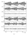
- a filtered speed signal n_filt and a filtered torque signal M_filt of motor 23 is shown for subsequent periods of time, where the filtering was performed with a bandpass filter in order to extract the first harmonic f2 from the respective signals n and M and where the uppermost diagrams of each filtered signal, n_filt1 and M_filt1, both show a first period of time at the beginning of one of the tests, the diagrams in the middle, n_filt2 and M_filt2, belong to a second period of time in the middle of the test, and the respective lowest diagrams, n_filt3 and M_filt3, both show a third period of time close to the end of the test.
- the general aim of the tests was to put the conveyor belt under considerable mechanical stress in order to simulate heavy operating conditions and in order to find out whether a weakening of the conveyor belt would be detectable in measured operating variables of motor 23.
- the conveyor belt 9 started to show clear signs of wear, and afterwards the test ended with the conveyor belt 9 starting to crack.
- n_filt and M_filt are reduced considerably, i.e. the amplitudes of the respective first harmonic f2 of the rotational belt frequency f1 are reduced, where these amplitudes equal to the peaks in the rotational speed n and the torque M of the motor caused by the splice region.
- This effect can be clearly seen not only in Fig. 7 but also in Figs. 5 and 6 where the amplitudes of n and M decrease towards the end of time axis t.
- a possible explanation for the reduced amplitudes is that the stiffness of the splice region fades with increased wearing of the belt material, so that the mechanical impact on the drive and idler pulleys is less intense.
- Torque M and rotational speed n are mechanical operating variables of motor 23. Since the torque M corresponds to the electrical current, similar effects as described above were also visible in this electrical operating variable of motor 23.
- FIG. 2 a top view of motor 23 and gear 24 applying a driving force to drive pulley 20 of conveyor belt 9 is shown.
- Motor 23 is a permanent magnet induction motor.
- a frequency converter 12 is installed.
- the frequency converter 12 receives current signals 1 and 2 from a current sensor unit 13, where the current signals 1 and 2 represent the stator currents of two of the three windings of motor 23.
- a processing unit 31 in converter 12 derives data signal 3 of the rotational speed n and data signal 7 of the torque M of motor 23 and determines signals for the voltages 32, 33, 34 to be applied to the three windings of motor 23.
- the three voltages 32 to 34 are then generated by the power electronic part of converter 12.
- a further data processing unit 6 which receives the data signals 3 and 7 of rotational speed and torque, respectively, from converter 12.
- Data processing unit 6 detects in at least one of the data signals 3 and 7 the irregularities or peaks which indicate that splice region 26 passed the drive pulley 20 and/or the idler pulley 21. These irregularities or peaks are detected for multiple points in time, so that a change in the shape or frequency of the irregularities can be recognized, and from this change it is determined whether the condition of the conveyor belt has changed or not.
- data processing unit 6 would detect an imminent crack in conveyor belt 9 from a reduction in the amplitude of the first harmonic f2 in data signal 3 or in data signal 7 or in both data signals or in corresponding frequency spectra.
- processing unit 6 sends a monitoring output signal 30, which preferably is a data message, to at least one of a display unit, a storage unit, such as a data logger or historian server, and/or a decision making unit.
- the output signal 30 reflects the detected change in the condition of the conveyor belt.
- the output signal 30 could for example be an alarm stating that a crack in conveyor belt 9 is likely to occur soon or it could be a direct instruction to stop the conveyor belt 9 as soon as possible and to carry out maintenance measures.
- Data signal 30 may be sent out continuously or only when a change in the condition of the conveyor belt occurs.
- a gearless motor 22 could be used, which is mechanically coupled in direct connection to the shaft or drum of drive pulley 20.
- a sensor signal 36 of the rotational speed of motor 22 is obtained by a speed encoder 10 and a sensor signal 37 of the torque by a torque transducer 11. These two sensor signals 36 and 37 are transmitted to the frequency converter 12, where they are processed and used in the above described way for the purpose of controlling the motor 22.
- the processing unit 31 generates from sensor signal 36 the data signal 3 of the rotational speed of motor 22 and sends it to the processing unit 6.
- the data signal 7 of the torque of motor 22 is generated from sensor signal 37 by the processing unit 6 instead of the processing unit 31 of converter 12.
- the data signals 3 and 7 are again used for the monitoring of the condition of conveyor belt 9 in the same way as described above.
- a vibration measurement unit 18 may deliver a vibration sensor signal 17, where the vibration measuring unit 18 measures the vibration of a mechanical part which is attached to motor 23, such as the drum of drive pulley 20, the gear 24 or a bearing in the shaft of drive pulley 20.
- the vibration sensor signal 17 the passing of splice region 26 at one of the pulleys 20 or 21 is detectable in a similar manner as in the operating variables of motor 23.
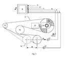
- FIG. 3 Further sensor information which may be used by processing unit 6 for improving the result of the condition monitoring is shown in Fig. 3 .
- the conveyor belt 9 is arranged to rotate further about a take-up pulley 16 and a further idler pulley 25.
- Take-up pulley 16 is used to apply a predefined tension to conveyor belt 9, where the tension is achieved through a displacement of the take-up pulley 16.
- the displacement 38 is measured by a distance measurement unit 15 and is delivered as a displacement sensor signal 5 to processing unit 6.
- the tension 39 of the conveyor belt 9 may be measured by a force measurement 14 and transmitted to processing unit 6 as a belt tension sensor signal 4.
- the processing unit 6 may take into account for the condition monitoring an image sensor signal 8 delivered by a radiation sensor 19 which observes the conveyor belt 9.
Landscapes
- Control Of Conveyors (AREA)
Claims (13)
- System zur Überwachung des Zustands eines Förderbands, bei dem das Förderband (9) angeordnet ist, um um wenigstens eine Antriebstrommel (20) und eine Umlenktrommel (21) zu rotieren und bei dem ein Elektromotor (22, 23) angeordnet ist, um die Antriebstrommel (20) anzutreiben, wobei das System Folgendes umfasst• wenigstens eine Datenverarbeitungseinheit (6),• wenigstens eine Sensoreinheit (10, 11, 13),wobei
die wenigstens eine Sensoreinheit (10, 11, 13) angeordnet ist, um wenigstens ein Sensorsignal (1, 2, 3, 7), das wenigstens eine Betriebsvariable des Elektromotors (22, 23) repräsentiert, zu ermitteln, und die wenigstens eine Datenverarbeitungseinheit (6, 31) angeordnet ist, um• aus dem wenigstens einen Sensorsignal (1, 2, 3, 7) wenigstens ein entsprechendes zeitabhängiges Datensignal abzuleiten,• Unregelmäßigkeiten (27, 28) in dem wenigstens einen Datensignal zu erkennen,• aus einer Änderung der Form oder Häufigkeit der Unregelmäßigkeiten (27, 28) zu ermitteln, ob sich der Zustand des Förderbands geändert hat, und• ein Überwachungsausgangssignal (30) zu senden, das eine Änderung des Zustands des Förderbands an wenigstens eine Anzeigeeinheit, eine Speichereinheit und/oder eine Entscheidungsfindungseinheit widerspiegelt,dadurch gekennzeichnet, dass die wenigstens eine Datenverarbeitungseinheit (6, 31) angeordnet ist, um Unregelmäßigkeiten (27, 28) in dem wenigstens einen Datensignal zu erkennen, die anzeigen, dass eine Spleißstelle (26) des Förderbands (9) die Antriebstrommel (20) und/oder die Umlenktrommel (21) passiert. - System nach dem Anspruch 1, bei dem die wenigstens eine Betriebsvariable entweder eine Spannung, ein Strom (1, 2), eine Rotationsdrehzahl (3), eine Beschleunigung, ein Drehmoment (7) oder eine Kraft ist.
- Verfahren nach dem Anspruch 1 oder 2, bei dem die wenigstens eine Sensoreinheit (10, 11, 13) ein Strom- und/oder Spannungssensor (13), ein Drehzahl-Impulsgeber (10), ein Drehmoment-Messwandler (11) oder ein Kraft-Messwandler ist.
- Verfahren nach einem beliebigen der vorstehenden Ansprüche, bei dem das wenigstens eine Datensignal eine Amplitude im Zeitverlauf oder ein Häufigkeitsspektrum repräsentiert.
- System nach einem beliebigen der vorstehenden Ansprüche, bei dem die wenigstens eine Datenverarbeitungseinheit (6) eine unabhängige Verarbeitungsvorrichtung und/oder ein integrierter Bestandteil eines elektrischen Wandlers (12) ist, bei dem der Wandler mit dem Elektromotor (22, 23) verbunden ist und angeordnet ist, diesen mit einem Strom und/oder einer Spannung zu versorgen.
- System nach einem beliebigen der vorstehenden Ansprüche, bei dem die wenigstens eine Datenverarbeitungseinheit angeordnet ist, um zu ermitteln, ob sich der Zustand des Förderbands geändert hat, indem sie die Form und/oder Häufigkeit der Unregelmäßigkeiten mit einer entsprechenden Schwelle oder mit der Form und Häufigkeit einer Referenz-Unregelmäßigkeit vergleicht oder indem sie einen modellgestützten Zustandsbeobachter verwendet.
- System nach einem beliebigen der vorstehenden Ansprüche, wobei die wenigstens eine Datenverarbeitungseinheit angeordnet ist, um eine Änderung in der Form der Unregelmäßigkeiten aus einer Änderung der Amplitudenhöhe und/oder aus einer Änderung in der Breite der Spitzenwerte der Unregelmäßigkeiten zu ermitteln.
- System nach einem beliebigen der vorstehenden Ansprüche, bei dem die wenigstens eine Sensoreinheit angeordnet ist, um ein erstes Sensorsignal (3) und ein zweites Sensorsignal (7), die jeweils eine erste (n) und eine zweite (M) Betriebsvariable des Elektromotors repräsentieren, zu ermitteln und bei dem die wenigstens eine Datenverarbeitungseinheit (6) angeordnet ist, um entsprechende erste und zweite Datensignale abzuleiten und Unregelmäßigkeiten entweder im ersten Datensignal (3) zu ermitteln, wenn die entsprechende Betriebsvariable (n) des Elektromotors gesteuert wird, um einer ersten Referenzvariablen zu folgen, oder im zweiten Datensignal (7) zu ermitteln, wenn die entsprechende Betriebsvariable (M) des Elektromotors gesteuert wird, um einer zweiten Referenzvariablen zu folgen.
- System nach einem beliebigen der vorstehenden Ansprüche, bei dem die wenigstens eine Datenverarbeitungseinheit angeordnet ist, um eine Änderung des Zustands des Förderbands zu ermitteln, indem sie weiterhin ein Schwingungssensorsignal (17) berücksichtigt, das von einer Schwingungsmesseinheit (18), die die Schwingung eines am Elektromotor angebrachten Maschinenbauteils misst, bereitgestellt wird.
- System nach einem beliebigen der vorstehenden Ansprüche, bei dem das Förderband angeordnet ist, um weiterhin um eine Spanntrommel (16) zu rotieren und bei dem die wenigstens eine Datenverarbeitungseinheit angeordnet ist, um eine Änderung des Zustands des Förderbands zu ermitteln, indem sie weiterhin ein Verlagerungssensorsignal (5) berücksichtigt, das von einer Entfernungsmesseinheit (15), die die Verlagerung der Spanntrommel (16) misst, bereitgestellt wird.
- System nach einem beliebigen der vorstehenden Ansprüche, bei dem die wenigstens eine Datenverarbeitungseinheit angeordnet ist, um eine Änderung des Zustands des Förderbands zu ermitteln, indem sie weiterhin ein Bandspannungssensorsignal (4) berücksichtigt, das von einer Kraftmesseinheit (14) bereitgestellt wird.
- System nach einem beliebigen der vorstehenden Ansprüche, bei dem die wenigstens eine Datenverarbeitungseinheit angeordnet ist, um eine Änderung des Zustands des Förderbands zu ermitteln, indem sie weiterhin ein Bildsensorsignal (8) berücksichtigt, das von einem Strahlungssensor (19), der das Förderband beobachtet, bereitgestellt wird.
- Verfahren zur Überwachung des Zustands eines Förderbands, bei dem das Förderband (9) angeordnet ist, um um wenigstens eine Antriebstrommel (20) und eine Umlenktrommel (21) zu rotieren und bei dem ein Elektromotor (22, 23) angeordnet ist, um die Antriebstrommel (20) anzutreiben,
die folgenden Schritte umfassend• Ermitteln wenigstens eines Sensorsignals (1, 2, 3, 7), das wenigstens eine Betriebsvariable des Elektromotors (22, 23) repräsentiert,• Ableiten wenigstens eines entsprechenden zeitabhängigen Datensignals aus dem wenigstens einen Sensorsignal (1, 2, 3, 7),• Erkennen von Unregelmäßigkeiten (27, 28) in dem wenigstens einen Datensignal,• Ermitteln, ob sich der Zustand des Förderbands geändert hat, aus einer Änderung der Form oder der Zeitpunkte (T1 bis T4) der Unregelmäßigkeiten (27, 28),• Senden eines Überwachungsausgangssignals (30), das eine Änderung des Zustands des Förderbands widerspiegelt, an wenigstens eine Anzeigeeinheit, eine Speichereinheit und/oder eine Entscheidungsfindungseinheit,gekennzeichnet durch den Schritt des Erkennens von Unregelmäßigkeiten (27, 28) in dem wenigstens einen Datensignal, die anzeigen, dass eine Spleißstelle (26) des Förderbands (9) die Antriebstrommel (20) und/oder die Umlenktrommel (21) passiert.
Priority Applications (1)
| Application Number | Priority Date | Filing Date | Title |
|---|---|---|---|
| PL12700972T PL2807096T3 (pl) | 2012-01-23 | 2012-01-23 | System i sposób monitorowania stanu taśmy przenośnika |
Applications Claiming Priority (1)
| Application Number | Priority Date | Filing Date | Title |
|---|---|---|---|
| PCT/EP2012/050949 WO2013110312A1 (en) | 2012-01-23 | 2012-01-23 | System and method for monitoring the condition of a conveyor belt |
Publications (2)
| Publication Number | Publication Date |
|---|---|
| EP2807096A1 EP2807096A1 (de) | 2014-12-03 |
| EP2807096B1 true EP2807096B1 (de) | 2015-10-07 |
Family
ID=45529087
Family Applications (1)
| Application Number | Title | Priority Date | Filing Date |
|---|---|---|---|
| EP12700972.8A Active EP2807096B1 (de) | 2012-01-23 | 2012-01-23 | System und verfahren zur überwachung des zustands eines förderbandes |
Country Status (8)
| Country | Link |
|---|---|
| US (1) | US9227793B2 (de) |
| EP (1) | EP2807096B1 (de) |
| CN (1) | CN104053616B (de) |
| AU (1) | AU2012367144B2 (de) |
| CA (1) | CA2862136A1 (de) |
| PL (1) | PL2807096T3 (de) |
| WO (1) | WO2013110312A1 (de) |
| ZA (1) | ZA201405183B (de) |
Cited By (1)
| Publication number | Priority date | Publication date | Assignee | Title |
|---|---|---|---|---|
| EP3540547B1 (de) | 2018-03-13 | 2022-07-20 | Gebhardt Fördertechnik GmbH | Verfahren zur funktionsüberwachung eines automatisierten fördersystems und entsprechendes fördersystem |
Families Citing this family (22)
| Publication number | Priority date | Publication date | Assignee | Title |
|---|---|---|---|---|
| US9359141B2 (en) | 2012-10-26 | 2016-06-07 | Laitram, L.L.C. | Positively-driven, low tension transfer conveyor |
| MX362056B (es) * | 2012-10-26 | 2019-01-07 | Laitram Llc | Transportador de transferencia de baja tensión, accionado positivamente. |
| US10399821B2 (en) | 2014-09-11 | 2019-09-03 | Otis Elevator Company | Vibration-based elevator tension member wear and life monitoring system |
| DE102015214159A1 (de) * | 2015-07-27 | 2017-02-02 | Phoenix Conveyor Belt Systems Gmbh | Förderanlage |
| JP6790339B2 (ja) * | 2015-08-24 | 2020-11-25 | 横浜ゴム株式会社 | コンベヤベルトのモニタリングシステム |
| EP3156337B1 (de) * | 2015-10-12 | 2018-04-11 | Becton Dickinson Rowa Germany GmbH | Verfahren zum betreiben einer verpackungsvorrichtung sowie verpackungsvorrichtung |
| DE102016111421A1 (de) * | 2016-06-22 | 2017-12-28 | Khs Gmbh | Transportvorrichtung und Verfahren zur Steuerung und Überwachung einer Transportvorrichtung |
| CN106542270A (zh) * | 2016-10-28 | 2017-03-29 | 津市市荣迪实业有限公司 | 皮带输送机 |
| JP6939271B2 (ja) * | 2017-08-31 | 2021-09-22 | 横浜ゴム株式会社 | コンベヤベルトのモニタリングシステム |
| AU2018247224B2 (en) | 2017-10-17 | 2022-07-14 | Joy Global Underground Mining Llc | Sensor systems and methods for detecting conveyor tension in a mining system |
| AU2018366033B2 (en) * | 2017-11-09 | 2021-09-16 | Gates Corporation | Belt drive monitoring system |
| EP3584199A1 (de) * | 2018-06-19 | 2019-12-25 | Siemens Aktiengesellschaft | Verfahren und system zur verschleisserkennung beim betreiben eines fördersystems |
| CN109409324B (zh) * | 2018-11-08 | 2022-09-09 | 深圳泰山体育科技有限公司 | 跑步机运行参数测量方法以及跑步机运行参数测量装置 |
| DE102019112868A1 (de) | 2019-01-23 | 2020-07-23 | Homag Gmbh | Transportsystem sowie Transportverfahren |
| RU188456U1 (ru) * | 2019-01-25 | 2019-04-15 | Федеральное государственное автономное образовательное учреждение высшего образования "Национальный исследовательский Томский политехнический университет" | Устройство приема-передачи сигнала системы контроля продольного разрыва полотна ленточного конвейера |
| CN110203644A (zh) * | 2019-05-10 | 2019-09-06 | 李江 | 输送线及输送线的失步检测方法 |
| US11401113B2 (en) | 2019-07-11 | 2022-08-02 | SYNCRUDE CANADA LTD. in trust for the owners of | Monitoring a transverse position of a conveyor belt and its material load by digital image analysis |
| CN110921241B (zh) * | 2019-11-18 | 2021-08-17 | 太仓北新建材有限公司 | 一种石膏板线皮带防刮伤方法及系统 |
| US12018995B2 (en) * | 2020-09-25 | 2024-06-25 | Braime Group Plc | System and method for pulley wear monitoring |
| CN113415602B (zh) * | 2021-06-21 | 2022-04-26 | 矿冶科技集团有限公司 | 皮带运输系统的故障检测方法、装置以及电子设备 |
| JP2023128604A (ja) * | 2022-03-04 | 2023-09-14 | 株式会社日立製作所 | ベルトコンベアの異常検知装置 |
| CN116654565A (zh) * | 2023-05-30 | 2023-08-29 | 北京力信德华科技有限公司 | 一种智能化运量检测装置、方法及输送系统 |
Family Cites Families (14)
| Publication number | Priority date | Publication date | Assignee | Title |
|---|---|---|---|---|
| DE3111219C2 (de) * | 1981-03-21 | 1984-03-29 | Alfred 5940 Lennestadt Tüschen | Einrichtung zur Sicherung des oder der Fördergurte einer Bandförderanlage gegen Längsschlitzung durch verklemmte Gegenstände |
| DE3131963A1 (de) * | 1981-08-13 | 1983-02-24 | Peter Lancier Maschinenbau-Hafenhütte GmbH & Co KG, 4400 Münster | Foerderanlagen- und laufrollenueberwachungssystem |
| US4436198A (en) | 1982-03-01 | 1984-03-13 | The B. F. Goodrich Company | Conveyor belt system having a phase shift indicator and adjuster for optimum tuning of a synchronous rip detector circuit |
| CN2223736Y (zh) * | 1993-11-18 | 1996-04-03 | 青岛建筑工程学院 | 输送带纵向防撕裂检测控制装置 |
| DE19643997C2 (de) | 1996-10-31 | 2002-12-05 | Contitech Transportbandsysteme | Verfahren zur Überwachung eines Fördergurtes |
| JPH11334852A (ja) * | 1998-05-27 | 1999-12-07 | Yokohama Rubber Co Ltd:The | ベルトコンベア装置 |
| US7308322B1 (en) * | 1998-09-29 | 2007-12-11 | Rockwell Automation Technologies, Inc. | Motorized system integrated control and diagnostics using vibration, pressure, temperature, speed, and/or current analysis |
| CN1231403C (zh) * | 2002-11-15 | 2005-12-14 | 谭孝冲 | 带式输送机胶带撕裂电流浮动差位对比监测保护方法 |
| DE102005055655A1 (de) | 2005-11-22 | 2007-05-31 | Siemens Ag | Vorrichtung zum Ermitteln des Zustandes eines Förderbandes |
| CN101443644A (zh) * | 2006-03-29 | 2009-05-27 | 马茨·利波夫斯基 | 用于检测传动带磨损和监视带传动系统性能的装置和方法 |
| DE102008018238A1 (de) | 2008-04-10 | 2009-10-15 | Rema Tip Top Gmbh | Vorrichtung und Verfahren zur zerstörungsfreien Überwachung des Betriebszustandes von Bauteilen aus Elastomeren |
| US9146175B2 (en) * | 2008-10-30 | 2015-09-29 | Abb Research Ltd | Method and a device for detecting abnormal changes in play in a transmission unit of a movable mechanical unit |
| DE102009052592A1 (de) * | 2009-11-10 | 2011-05-12 | GM Global Technology Operations LLC, Detroit | Fördereinrichtung |
| CN202063531U (zh) * | 2011-05-05 | 2011-12-07 | 李明洁 | 空芯砖机传送带控制装置 |
-
2012
- 2012-01-23 EP EP12700972.8A patent/EP2807096B1/de active Active
- 2012-01-23 WO PCT/EP2012/050949 patent/WO2013110312A1/en not_active Ceased
- 2012-01-23 PL PL12700972T patent/PL2807096T3/pl unknown
- 2012-01-23 CN CN201280067873.3A patent/CN104053616B/zh active Active
- 2012-01-23 CA CA2862136A patent/CA2862136A1/en not_active Abandoned
- 2012-01-23 AU AU2012367144A patent/AU2012367144B2/en not_active Ceased
-
2014
- 2014-07-15 ZA ZA2014/05183A patent/ZA201405183B/en unknown
- 2014-07-23 US US14/338,977 patent/US9227793B2/en not_active Expired - Fee Related
Cited By (1)
| Publication number | Priority date | Publication date | Assignee | Title |
|---|---|---|---|---|
| EP3540547B1 (de) | 2018-03-13 | 2022-07-20 | Gebhardt Fördertechnik GmbH | Verfahren zur funktionsüberwachung eines automatisierten fördersystems und entsprechendes fördersystem |
Also Published As
| Publication number | Publication date |
|---|---|
| WO2013110312A1 (en) | 2013-08-01 |
| AU2012367144B2 (en) | 2015-08-06 |
| US20140336812A1 (en) | 2014-11-13 |
| PL2807096T3 (pl) | 2016-03-31 |
| US9227793B2 (en) | 2016-01-05 |
| ZA201405183B (en) | 2015-11-25 |
| AU2012367144A1 (en) | 2014-07-03 |
| CA2862136A1 (en) | 2013-08-01 |
| CN104053616A (zh) | 2014-09-17 |
| CN104053616B (zh) | 2016-05-25 |
| EP2807096A1 (de) | 2014-12-03 |
Similar Documents
| Publication | Publication Date | Title |
|---|---|---|
| EP2807096B1 (de) | System und verfahren zur überwachung des zustands eines förderbandes | |
| US7494004B2 (en) | Method and apparatus for monitoring conveyor belts | |
| AU2014265091B2 (en) | Method for monitoring conveyor belt splices | |
| EP1783070B1 (de) | Verfahren zur Selbstsynchronisierung eines Sensorsystems für ein Förderband | |
| US5168266A (en) | Method for detecting longitudinal tear in a conveyor belt | |
| EP3424849B1 (de) | Verschleissdetektionsvorrichtung für förderband | |
| US8191703B2 (en) | Conveyor system monitoring and maintenance | |
| US20080257692A1 (en) | Sensor system for conveyor belt | |
| EP2186757A1 (de) | Förderbandrissdetektionssystem | |
| US20090120768A1 (en) | Device for monitoring a conveyor | |
| FI127826B (en) | Method of detecting a worn link in a chain, and lifting device | |
| JP4873359B2 (ja) | コンベヤベルトの縦裂検出装置 | |
| EP2815993B1 (de) | Spleißüberwachungssystem für Förderbänder in der Bergbauindustrie | |
| WO2013062428A1 (en) | System for continuous detection of cord defects in flat steel-plastic elevator ropes | |
| US20250250120A1 (en) | Systems and methods for determining operational conditions of a linear motor conveyor system | |
| US20240183748A1 (en) | Transmission belt arrangement | |
| US20240183749A1 (en) | Transmission belt arrangement | |
| Joshi et al. | Chapter-40 Surveillance System of Conveyor Belt’s Health-A Review | |
| WO2019003368A1 (ja) | 回転機の診断装置、診断方法および回転機システム | |
| CN118125036A (zh) | 传送带装置 | |
| AT16482U1 (de) | System zur Überwachung des Zustands eines Förderbands |
Legal Events
| Date | Code | Title | Description |
|---|---|---|---|
| PUAI | Public reference made under article 153(3) epc to a published international application that has entered the european phase |
Free format text: ORIGINAL CODE: 0009012 |
|
| 17P | Request for examination filed |
Effective date: 20140606 |
|
| AK | Designated contracting states |
Kind code of ref document: A1 Designated state(s): AL AT BE BG CH CY CZ DE DK EE ES FI FR GB GR HR HU IE IS IT LI LT LU LV MC MK MT NL NO PL PT RO RS SE SI SK SM TR |
|
| DAX | Request for extension of the european patent (deleted) | ||
| GRAP | Despatch of communication of intention to grant a patent |
Free format text: ORIGINAL CODE: EPIDOSNIGR1 |
|
| INTG | Intention to grant announced |
Effective date: 20150721 |
|
| GRAS | Grant fee paid |
Free format text: ORIGINAL CODE: EPIDOSNIGR3 |
|
| GRAA | (expected) grant |
Free format text: ORIGINAL CODE: 0009210 |
|
| AK | Designated contracting states |
Kind code of ref document: B1 Designated state(s): AL AT BE BG CH CY CZ DE DK EE ES FI FR GB GR HR HU IE IS IT LI LT LU LV MC MK MT NL NO PL PT RO RS SE SI SK SM TR |
|
| REG | Reference to a national code |
Ref country code: GB Ref legal event code: FG4D |
|
| REG | Reference to a national code |
Ref country code: AT Ref legal event code: REF Ref document number: 753603 Country of ref document: AT Kind code of ref document: T Effective date: 20151015 Ref country code: CH Ref legal event code: EP |
|
| REG | Reference to a national code |
Ref country code: IE Ref legal event code: FG4D |
|
| REG | Reference to a national code |
Ref country code: DE Ref legal event code: R096 Ref document number: 602012011307 Country of ref document: DE |
|
| REG | Reference to a national code |
Ref country code: NL Ref legal event code: MP Effective date: 20151007 |
|
| REG | Reference to a national code |
Ref country code: AT Ref legal event code: MK05 Ref document number: 753603 Country of ref document: AT Kind code of ref document: T Effective date: 20151007 |
|
| REG | Reference to a national code |
Ref country code: LT Ref legal event code: MG4D |
|
| PG25 | Lapsed in a contracting state [announced via postgrant information from national office to epo] |
Ref country code: HR Free format text: LAPSE BECAUSE OF FAILURE TO SUBMIT A TRANSLATION OF THE DESCRIPTION OR TO PAY THE FEE WITHIN THE PRESCRIBED TIME-LIMIT Effective date: 20151007 Ref country code: IS Free format text: LAPSE BECAUSE OF FAILURE TO SUBMIT A TRANSLATION OF THE DESCRIPTION OR TO PAY THE FEE WITHIN THE PRESCRIBED TIME-LIMIT Effective date: 20160207 Ref country code: IT Free format text: LAPSE BECAUSE OF FAILURE TO SUBMIT A TRANSLATION OF THE DESCRIPTION OR TO PAY THE FEE WITHIN THE PRESCRIBED TIME-LIMIT Effective date: 20151007 Ref country code: NL Free format text: LAPSE BECAUSE OF FAILURE TO SUBMIT A TRANSLATION OF THE DESCRIPTION OR TO PAY THE FEE WITHIN THE PRESCRIBED TIME-LIMIT Effective date: 20151007 Ref country code: LT Free format text: LAPSE BECAUSE OF FAILURE TO SUBMIT A TRANSLATION OF THE DESCRIPTION OR TO PAY THE FEE WITHIN THE PRESCRIBED TIME-LIMIT Effective date: 20151007 Ref country code: ES Free format text: LAPSE BECAUSE OF FAILURE TO SUBMIT A TRANSLATION OF THE DESCRIPTION OR TO PAY THE FEE WITHIN THE PRESCRIBED TIME-LIMIT Effective date: 20151007 Ref country code: NO Free format text: LAPSE BECAUSE OF FAILURE TO SUBMIT A TRANSLATION OF THE DESCRIPTION OR TO PAY THE FEE WITHIN THE PRESCRIBED TIME-LIMIT Effective date: 20160107 |
|
| PG25 | Lapsed in a contracting state [announced via postgrant information from national office to epo] |
Ref country code: LV Free format text: LAPSE BECAUSE OF FAILURE TO SUBMIT A TRANSLATION OF THE DESCRIPTION OR TO PAY THE FEE WITHIN THE PRESCRIBED TIME-LIMIT Effective date: 20151007 Ref country code: SE Free format text: LAPSE BECAUSE OF FAILURE TO SUBMIT A TRANSLATION OF THE DESCRIPTION OR TO PAY THE FEE WITHIN THE PRESCRIBED TIME-LIMIT Effective date: 20151007 Ref country code: RS Free format text: LAPSE BECAUSE OF FAILURE TO SUBMIT A TRANSLATION OF THE DESCRIPTION OR TO PAY THE FEE WITHIN THE PRESCRIBED TIME-LIMIT Effective date: 20151007 Ref country code: FI Free format text: LAPSE BECAUSE OF FAILURE TO SUBMIT A TRANSLATION OF THE DESCRIPTION OR TO PAY THE FEE WITHIN THE PRESCRIBED TIME-LIMIT Effective date: 20151007 Ref country code: PT Free format text: LAPSE BECAUSE OF FAILURE TO SUBMIT A TRANSLATION OF THE DESCRIPTION OR TO PAY THE FEE WITHIN THE PRESCRIBED TIME-LIMIT Effective date: 20160208 Ref country code: AT Free format text: LAPSE BECAUSE OF FAILURE TO SUBMIT A TRANSLATION OF THE DESCRIPTION OR TO PAY THE FEE WITHIN THE PRESCRIBED TIME-LIMIT Effective date: 20151007 Ref country code: BE Free format text: LAPSE BECAUSE OF NON-PAYMENT OF DUE FEES Effective date: 20160131 Ref country code: GR Free format text: LAPSE BECAUSE OF FAILURE TO SUBMIT A TRANSLATION OF THE DESCRIPTION OR TO PAY THE FEE WITHIN THE PRESCRIBED TIME-LIMIT Effective date: 20160108 |
|
| REG | Reference to a national code |
Ref country code: DE Ref legal event code: R097 Ref document number: 602012011307 Country of ref document: DE |
|
| PG25 | Lapsed in a contracting state [announced via postgrant information from national office to epo] |
Ref country code: CZ Free format text: LAPSE BECAUSE OF FAILURE TO SUBMIT A TRANSLATION OF THE DESCRIPTION OR TO PAY THE FEE WITHIN THE PRESCRIBED TIME-LIMIT Effective date: 20151007 |
|
| REG | Reference to a national code |
Ref country code: DE Ref legal event code: R081 Ref document number: 602012011307 Country of ref document: DE Owner name: ABB SCHWEIZ AG, CH Free format text: FORMER OWNER: ABB TECHNOLOGY AG, ZUERICH, CH |
|
| PLBE | No opposition filed within time limit |
Free format text: ORIGINAL CODE: 0009261 |
|
| STAA | Information on the status of an ep patent application or granted ep patent |
Free format text: STATUS: NO OPPOSITION FILED WITHIN TIME LIMIT |
|
| PG25 | Lapsed in a contracting state [announced via postgrant information from national office to epo] |
Ref country code: DK Free format text: LAPSE BECAUSE OF FAILURE TO SUBMIT A TRANSLATION OF THE DESCRIPTION OR TO PAY THE FEE WITHIN THE PRESCRIBED TIME-LIMIT Effective date: 20151007 Ref country code: RO Free format text: LAPSE BECAUSE OF FAILURE TO SUBMIT A TRANSLATION OF THE DESCRIPTION OR TO PAY THE FEE WITHIN THE PRESCRIBED TIME-LIMIT Effective date: 20151007 Ref country code: SM Free format text: LAPSE BECAUSE OF FAILURE TO SUBMIT A TRANSLATION OF THE DESCRIPTION OR TO PAY THE FEE WITHIN THE PRESCRIBED TIME-LIMIT Effective date: 20151007 Ref country code: LU Free format text: LAPSE BECAUSE OF FAILURE TO SUBMIT A TRANSLATION OF THE DESCRIPTION OR TO PAY THE FEE WITHIN THE PRESCRIBED TIME-LIMIT Effective date: 20160123 Ref country code: SK Free format text: LAPSE BECAUSE OF FAILURE TO SUBMIT A TRANSLATION OF THE DESCRIPTION OR TO PAY THE FEE WITHIN THE PRESCRIBED TIME-LIMIT Effective date: 20151007 Ref country code: EE Free format text: LAPSE BECAUSE OF FAILURE TO SUBMIT A TRANSLATION OF THE DESCRIPTION OR TO PAY THE FEE WITHIN THE PRESCRIBED TIME-LIMIT Effective date: 20151007 |
|
| REG | Reference to a national code |
Ref country code: CH Ref legal event code: PL |
|
| 26N | No opposition filed |
Effective date: 20160708 |
|
| GBPC | Gb: european patent ceased through non-payment of renewal fee |
Effective date: 20160123 |
|
| PG25 | Lapsed in a contracting state [announced via postgrant information from national office to epo] |
Ref country code: MC Free format text: LAPSE BECAUSE OF FAILURE TO SUBMIT A TRANSLATION OF THE DESCRIPTION OR TO PAY THE FEE WITHIN THE PRESCRIBED TIME-LIMIT Effective date: 20151007 |
|
| REG | Reference to a national code |
Ref country code: FR Ref legal event code: ST Effective date: 20160930 |
|
| PG25 | Lapsed in a contracting state [announced via postgrant information from national office to epo] |
Ref country code: LI Free format text: LAPSE BECAUSE OF NON-PAYMENT OF DUE FEES Effective date: 20160131 Ref country code: CH Free format text: LAPSE BECAUSE OF NON-PAYMENT OF DUE FEES Effective date: 20160131 Ref country code: GB Free format text: LAPSE BECAUSE OF NON-PAYMENT OF DUE FEES Effective date: 20160123 |
|
| REG | Reference to a national code |
Ref country code: IE Ref legal event code: MM4A |
|
| PG25 | Lapsed in a contracting state [announced via postgrant information from national office to epo] |
Ref country code: FR Free format text: LAPSE BECAUSE OF NON-PAYMENT OF DUE FEES Effective date: 20160201 Ref country code: SI Free format text: LAPSE BECAUSE OF FAILURE TO SUBMIT A TRANSLATION OF THE DESCRIPTION OR TO PAY THE FEE WITHIN THE PRESCRIBED TIME-LIMIT Effective date: 20151007 |
|
| PG25 | Lapsed in a contracting state [announced via postgrant information from national office to epo] |
Ref country code: BE Free format text: LAPSE BECAUSE OF FAILURE TO SUBMIT A TRANSLATION OF THE DESCRIPTION OR TO PAY THE FEE WITHIN THE PRESCRIBED TIME-LIMIT Effective date: 20151007 |
|
| PG25 | Lapsed in a contracting state [announced via postgrant information from national office to epo] |
Ref country code: IE Free format text: LAPSE BECAUSE OF NON-PAYMENT OF DUE FEES Effective date: 20160123 |
|
| REG | Reference to a national code |
Ref country code: DE Ref legal event code: R081 Ref document number: 602012011307 Country of ref document: DE Owner name: ABB SCHWEIZ AG, CH Free format text: FORMER OWNER: ABB SCHWEIZ AG, BADEN, CH |
|
| PG25 | Lapsed in a contracting state [announced via postgrant information from national office to epo] |
Ref country code: MT Free format text: LAPSE BECAUSE OF FAILURE TO SUBMIT A TRANSLATION OF THE DESCRIPTION OR TO PAY THE FEE WITHIN THE PRESCRIBED TIME-LIMIT Effective date: 20151007 |
|
| PG25 | Lapsed in a contracting state [announced via postgrant information from national office to epo] |
Ref country code: HU Free format text: LAPSE BECAUSE OF FAILURE TO SUBMIT A TRANSLATION OF THE DESCRIPTION OR TO PAY THE FEE WITHIN THE PRESCRIBED TIME-LIMIT; INVALID AB INITIO Effective date: 20120123 |
|
| PG25 | Lapsed in a contracting state [announced via postgrant information from national office to epo] |
Ref country code: MK Free format text: LAPSE BECAUSE OF FAILURE TO SUBMIT A TRANSLATION OF THE DESCRIPTION OR TO PAY THE FEE WITHIN THE PRESCRIBED TIME-LIMIT Effective date: 20151007 Ref country code: CY Free format text: LAPSE BECAUSE OF FAILURE TO SUBMIT A TRANSLATION OF THE DESCRIPTION OR TO PAY THE FEE WITHIN THE PRESCRIBED TIME-LIMIT Effective date: 20151007 Ref country code: MT Free format text: LAPSE BECAUSE OF FAILURE TO SUBMIT A TRANSLATION OF THE DESCRIPTION OR TO PAY THE FEE WITHIN THE PRESCRIBED TIME-LIMIT Effective date: 20160131 |
|
| PG25 | Lapsed in a contracting state [announced via postgrant information from national office to epo] |
Ref country code: BG Free format text: LAPSE BECAUSE OF FAILURE TO SUBMIT A TRANSLATION OF THE DESCRIPTION OR TO PAY THE FEE WITHIN THE PRESCRIBED TIME-LIMIT Effective date: 20151007 |
|
| PG25 | Lapsed in a contracting state [announced via postgrant information from national office to epo] |
Ref country code: AL Free format text: LAPSE BECAUSE OF FAILURE TO SUBMIT A TRANSLATION OF THE DESCRIPTION OR TO PAY THE FEE WITHIN THE PRESCRIBED TIME-LIMIT Effective date: 20151007 Ref country code: TR Free format text: LAPSE BECAUSE OF FAILURE TO SUBMIT A TRANSLATION OF THE DESCRIPTION OR TO PAY THE FEE WITHIN THE PRESCRIBED TIME-LIMIT Effective date: 20151007 |
|
| PGFP | Annual fee paid to national office [announced via postgrant information from national office to epo] |
Ref country code: DE Payment date: 20250121 Year of fee payment: 14 |
|
| PGFP | Annual fee paid to national office [announced via postgrant information from national office to epo] |
Ref country code: PL Payment date: 20250113 Year of fee payment: 14 |