EP2806962B1 - Élément filtrant et procédé de fabrication d'un élément filtrant - Google Patents
Élément filtrant et procédé de fabrication d'un élément filtrant Download PDFInfo
- Publication number
- EP2806962B1 EP2806962B1 EP12703731.5A EP12703731A EP2806962B1 EP 2806962 B1 EP2806962 B1 EP 2806962B1 EP 12703731 A EP12703731 A EP 12703731A EP 2806962 B1 EP2806962 B1 EP 2806962B1
- Authority
- EP
- European Patent Office
- Prior art keywords
- filter
- melt adhesive
- hot
- adhesive
- weight
- Prior art date
- Legal status (The legal status is an assumption and is not a legal conclusion. Google has not performed a legal analysis and makes no representation as to the accuracy of the status listed.)
- Active
Links
- 238000004519 manufacturing process Methods 0.000 title claims description 10
- 239000004831 Hot glue Substances 0.000 claims description 238
- 239000000853 adhesive Substances 0.000 claims description 115
- 230000001070 adhesive effect Effects 0.000 claims description 115
- 238000007789 sealing Methods 0.000 claims description 68
- 239000000203 mixture Substances 0.000 claims description 63
- 239000000463 material Substances 0.000 claims description 43
- 229920000728 polyester Polymers 0.000 claims description 38
- 229920002647 polyamide Polymers 0.000 claims description 31
- WNLRTRBMVRJNCN-UHFFFAOYSA-N adipic acid Chemical compound OC(=O)CCCCC(O)=O WNLRTRBMVRJNCN-UHFFFAOYSA-N 0.000 claims description 22
- 230000000087 stabilizing effect Effects 0.000 claims description 21
- 238000000034 method Methods 0.000 claims description 17
- 239000011265 semifinished product Substances 0.000 claims description 15
- 238000002844 melting Methods 0.000 claims description 14
- 230000008018 melting Effects 0.000 claims description 14
- GWEVSGVZZGPLCZ-UHFFFAOYSA-N Titan oxide Chemical compound O=[Ti]=O GWEVSGVZZGPLCZ-UHFFFAOYSA-N 0.000 claims description 13
- 239000000155 melt Substances 0.000 claims description 11
- 238000002156 mixing Methods 0.000 claims description 11
- 239000001361 adipic acid Substances 0.000 claims description 10
- 235000011037 adipic acid Nutrition 0.000 claims description 10
- 239000008187 granular material Substances 0.000 claims description 6
- 239000000049 pigment Substances 0.000 claims description 6
- 229920002635 polyurethane Polymers 0.000 claims description 6
- 239000004814 polyurethane Substances 0.000 claims description 6
- 229920005989 resin Polymers 0.000 claims description 6
- 239000011347 resin Substances 0.000 claims description 6
- 239000004408 titanium dioxide Substances 0.000 claims description 6
- 239000012463 white pigment Substances 0.000 claims description 6
- 239000004744 fabric Substances 0.000 claims description 4
- 239000003292 glue Substances 0.000 claims description 4
- 238000010438 heat treatment Methods 0.000 claims description 4
- 238000004026 adhesive bonding Methods 0.000 claims description 3
- 239000000843 powder Substances 0.000 claims description 3
- 229920000642 polymer Polymers 0.000 claims description 2
- 239000010410 layer Substances 0.000 description 69
- 239000012530 fluid Substances 0.000 description 14
- 229910052751 metal Inorganic materials 0.000 description 14
- 239000002184 metal Substances 0.000 description 14
- 239000004033 plastic Substances 0.000 description 13
- 229920003023 plastic Polymers 0.000 description 13
- 238000011144 upstream manufacturing Methods 0.000 description 12
- 239000004952 Polyamide Substances 0.000 description 11
- 239000000835 fiber Substances 0.000 description 9
- 239000007788 liquid Substances 0.000 description 9
- KKEYFWRCBNTPAC-UHFFFAOYSA-N Terephthalic acid Chemical compound OC(=O)C1=CC=C(C(O)=O)C=C1 KKEYFWRCBNTPAC-UHFFFAOYSA-N 0.000 description 8
- JBKVHLHDHHXQEQ-UHFFFAOYSA-N epsilon-caprolactam Chemical compound O=C1CCCCCN1 JBKVHLHDHHXQEQ-UHFFFAOYSA-N 0.000 description 8
- 238000001914 filtration Methods 0.000 description 7
- 230000037303 wrinkles Effects 0.000 description 7
- IJGRMHOSHXDMSA-UHFFFAOYSA-N Atomic nitrogen Chemical compound N#N IJGRMHOSHXDMSA-UHFFFAOYSA-N 0.000 description 6
- 239000000945 filler Substances 0.000 description 6
- 239000000446 fuel Substances 0.000 description 6
- 238000000926 separation method Methods 0.000 description 6
- 239000000654 additive Substances 0.000 description 5
- NAQMVNRVTILPCV-UHFFFAOYSA-N hexane-1,6-diamine Chemical compound NCCCCCCN NAQMVNRVTILPCV-UHFFFAOYSA-N 0.000 description 5
- RNLHGQLZWXBQNY-UHFFFAOYSA-N 3-(aminomethyl)-3,5,5-trimethylcyclohexan-1-amine Chemical compound CC1(C)CC(N)CC(C)(CN)C1 RNLHGQLZWXBQNY-UHFFFAOYSA-N 0.000 description 4
- 239000002253 acid Substances 0.000 description 4
- 150000001412 amines Chemical class 0.000 description 4
- 238000001816 cooling Methods 0.000 description 4
- MTHSVFCYNBDYFN-UHFFFAOYSA-N diethylene glycol Chemical compound OCCOCCO MTHSVFCYNBDYFN-UHFFFAOYSA-N 0.000 description 4
- 239000007789 gas Substances 0.000 description 4
- 239000003921 oil Substances 0.000 description 4
- 238000003825 pressing Methods 0.000 description 4
- CXMXRPHRNRROMY-UHFFFAOYSA-N sebacic acid Chemical compound OC(=O)CCCCCCCCC(O)=O CXMXRPHRNRROMY-UHFFFAOYSA-N 0.000 description 4
- 229920001169 thermoplastic Polymers 0.000 description 4
- 239000004416 thermosoftening plastic Substances 0.000 description 4
- 238000004804 winding Methods 0.000 description 4
- JCUZDQXWVYNXHD-UHFFFAOYSA-N 2,2,4-trimethylhexane-1,6-diamine Chemical compound NCCC(C)CC(C)(C)CN JCUZDQXWVYNXHD-UHFFFAOYSA-N 0.000 description 3
- LYCAIKOWRPUZTN-UHFFFAOYSA-N Ethylene glycol Chemical compound OCCO LYCAIKOWRPUZTN-UHFFFAOYSA-N 0.000 description 3
- GLUUGHFHXGJENI-UHFFFAOYSA-N Piperazine Chemical compound C1CNCCN1 GLUUGHFHXGJENI-UHFFFAOYSA-N 0.000 description 3
- 230000000996 additive effect Effects 0.000 description 3
- 239000003570 air Substances 0.000 description 3
- WERYXYBDKMZEQL-UHFFFAOYSA-N butane-1,4-diol Chemical compound OCCCCO WERYXYBDKMZEQL-UHFFFAOYSA-N 0.000 description 3
- 238000002485 combustion reaction Methods 0.000 description 3
- 150000002009 diols Chemical class 0.000 description 3
- 229910052757 nitrogen Inorganic materials 0.000 description 3
- 238000005204 segregation Methods 0.000 description 3
- 230000006641 stabilisation Effects 0.000 description 3
- 238000011105 stabilization Methods 0.000 description 3
- PIICEJLVQHRZGT-UHFFFAOYSA-N Ethylenediamine Chemical compound NCCN PIICEJLVQHRZGT-UHFFFAOYSA-N 0.000 description 2
- 229910000831 Steel Inorganic materials 0.000 description 2
- ORLQHILJRHBSAY-UHFFFAOYSA-N [1-(hydroxymethyl)cyclohexyl]methanol Chemical compound OCC1(CO)CCCCC1 ORLQHILJRHBSAY-UHFFFAOYSA-N 0.000 description 2
- 150000007513 acids Chemical class 0.000 description 2
- 239000012790 adhesive layer Substances 0.000 description 2
- 125000001931 aliphatic group Chemical group 0.000 description 2
- 230000000712 assembly Effects 0.000 description 2
- 238000000429 assembly Methods 0.000 description 2
- 230000015572 biosynthetic process Effects 0.000 description 2
- CDQSJQSWAWPGKG-UHFFFAOYSA-N butane-1,1-diol Chemical compound CCCC(O)O CDQSJQSWAWPGKG-UHFFFAOYSA-N 0.000 description 2
- 238000004891 communication Methods 0.000 description 2
- 150000001875 compounds Chemical class 0.000 description 2
- 238000010276 construction Methods 0.000 description 2
- XXMIOPMDWAUFGU-UHFFFAOYSA-N hexane-1,6-diol Chemical compound OCCCCCCO XXMIOPMDWAUFGU-UHFFFAOYSA-N 0.000 description 2
- 229920006270 hydrocarbon resin Polymers 0.000 description 2
- 238000009434 installation Methods 0.000 description 2
- QQVIHTHCMHWDBS-UHFFFAOYSA-N isophthalic acid Chemical compound OC(=O)C1=CC=CC(C(O)=O)=C1 QQVIHTHCMHWDBS-UHFFFAOYSA-N 0.000 description 2
- SLCVBVWXLSEKPL-UHFFFAOYSA-N neopentyl glycol Chemical compound OCC(C)(C)CO SLCVBVWXLSEKPL-UHFFFAOYSA-N 0.000 description 2
- 229940117969 neopentyl glycol Drugs 0.000 description 2
- BDJRBEYXGGNYIS-UHFFFAOYSA-N nonanedioic acid Chemical compound OC(=O)CCCCCCCC(O)=O BDJRBEYXGGNYIS-UHFFFAOYSA-N 0.000 description 2
- 239000004745 nonwoven fabric Substances 0.000 description 2
- 239000012188 paraffin wax Substances 0.000 description 2
- XNGIFLGASWRNHJ-UHFFFAOYSA-N phthalic acid Chemical compound OC(=O)C1=CC=CC=C1C(O)=O XNGIFLGASWRNHJ-UHFFFAOYSA-N 0.000 description 2
- 238000006068 polycondensation reaction Methods 0.000 description 2
- 239000002243 precursor Substances 0.000 description 2
- 238000002360 preparation method Methods 0.000 description 2
- 125000006850 spacer group Chemical class 0.000 description 2
- 239000010959 steel Substances 0.000 description 2
- 239000000758 substrate Substances 0.000 description 2
- KDYFGRWQOYBRFD-UHFFFAOYSA-N succinic acid Chemical compound OC(=O)CCC(O)=O KDYFGRWQOYBRFD-UHFFFAOYSA-N 0.000 description 2
- 239000004753 textile Substances 0.000 description 2
- WTHDKMILWLGDKL-UHFFFAOYSA-N urea;hydrate Chemical compound O.NC(N)=O WTHDKMILWLGDKL-UHFFFAOYSA-N 0.000 description 2
- 239000001993 wax Substances 0.000 description 2
- 238000003466 welding Methods 0.000 description 2
- IWHLYPDWHHPVAA-UHFFFAOYSA-N 6-hydroxyhexanoic acid Chemical compound OCCCCCC(O)=O IWHLYPDWHHPVAA-UHFFFAOYSA-N 0.000 description 1
- RSWGJHLUYNHPMX-UHFFFAOYSA-N Abietic-Saeure Natural products C12CCC(C(C)C)=CC2=CCC2C1(C)CCCC2(C)C(O)=O RSWGJHLUYNHPMX-UHFFFAOYSA-N 0.000 description 1
- 240000006829 Ficus sundaica Species 0.000 description 1
- 239000013032 Hydrocarbon resin Substances 0.000 description 1
- -1 Luft Chemical compound 0.000 description 1
- KHPCPRHQVVSZAH-HUOMCSJISA-N Rosin Natural products O(C/C=C/c1ccccc1)[C@H]1[C@H](O)[C@@H](O)[C@@H](O)[C@@H](CO)O1 KHPCPRHQVVSZAH-HUOMCSJISA-N 0.000 description 1
- VYPSYNLAJGMNEJ-UHFFFAOYSA-N Silicium dioxide Chemical compound O=[Si]=O VYPSYNLAJGMNEJ-UHFFFAOYSA-N 0.000 description 1
- 125000002723 alicyclic group Chemical group 0.000 description 1
- 150000008064 anhydrides Chemical class 0.000 description 1
- 125000003118 aryl group Chemical group 0.000 description 1
- BRPQOXSCLDDYGP-UHFFFAOYSA-N calcium oxide Chemical compound [O-2].[Ca+2] BRPQOXSCLDDYGP-UHFFFAOYSA-N 0.000 description 1
- 239000000292 calcium oxide Substances 0.000 description 1
- ODINCKMPIJJUCX-UHFFFAOYSA-N calcium oxide Inorganic materials [Ca]=O ODINCKMPIJJUCX-UHFFFAOYSA-N 0.000 description 1
- 150000001718 carbodiimides Chemical class 0.000 description 1
- 239000001913 cellulose Substances 0.000 description 1
- 229920002678 cellulose Polymers 0.000 description 1
- 238000002425 crystallisation Methods 0.000 description 1
- 230000008025 crystallization Effects 0.000 description 1
- 235000014113 dietary fatty acids Nutrition 0.000 description 1
- 239000000539 dimer Substances 0.000 description 1
- 230000000694 effects Effects 0.000 description 1
- 150000002148 esters Chemical class 0.000 description 1
- 239000000194 fatty acid Substances 0.000 description 1
- 229930195729 fatty acid Natural products 0.000 description 1
- 150000004665 fatty acids Chemical class 0.000 description 1
- 238000005187 foaming Methods 0.000 description 1
- 238000009472 formulation Methods 0.000 description 1
- 229910021485 fumed silica Inorganic materials 0.000 description 1
- 239000012943 hotmelt Substances 0.000 description 1
- 230000007062 hydrolysis Effects 0.000 description 1
- 238000006460 hydrolysis reaction Methods 0.000 description 1
- 239000010687 lubricating oil Substances 0.000 description 1
- 238000003754 machining Methods 0.000 description 1
- 238000005555 metalworking Methods 0.000 description 1
- 239000003209 petroleum derivative Substances 0.000 description 1
- 229920006149 polyester-amide block copolymer Polymers 0.000 description 1
- 229910052573 porcelain Inorganic materials 0.000 description 1
- 238000004382 potting Methods 0.000 description 1
- 239000000047 product Substances 0.000 description 1
- 239000002994 raw material Substances 0.000 description 1
- 230000000284 resting effect Effects 0.000 description 1
- 238000005096 rolling process Methods 0.000 description 1
- 239000000565 sealant Substances 0.000 description 1
- 239000007787 solid Substances 0.000 description 1
- 239000000126 substance Substances 0.000 description 1
- 229960005137 succinic acid Drugs 0.000 description 1
- 230000008961 swelling Effects 0.000 description 1
- KHPCPRHQVVSZAH-UHFFFAOYSA-N trans-cinnamyl beta-D-glucopyranoside Natural products OC1C(O)C(O)C(CO)OC1OCC=CC1=CC=CC=C1 KHPCPRHQVVSZAH-UHFFFAOYSA-N 0.000 description 1
Images


Classifications
-
- B—PERFORMING OPERATIONS; TRANSPORTING
- B01—PHYSICAL OR CHEMICAL PROCESSES OR APPARATUS IN GENERAL
- B01D—SEPARATION
- B01D46/00—Filters or filtering processes specially modified for separating dispersed particles from gases or vapours
- B01D46/0002—Casings; Housings; Frame constructions
- B01D46/0005—Mounting of filtering elements within casings, housings or frames
-
- B—PERFORMING OPERATIONS; TRANSPORTING
- B01—PHYSICAL OR CHEMICAL PROCESSES OR APPARATUS IN GENERAL
- B01D—SEPARATION
- B01D46/00—Filters or filtering processes specially modified for separating dispersed particles from gases or vapours
- B01D46/42—Auxiliary equipment or operation thereof
- B01D46/4227—Manipulating filters or filter elements, e.g. handles or extracting tools
-
- B—PERFORMING OPERATIONS; TRANSPORTING
- B01—PHYSICAL OR CHEMICAL PROCESSES OR APPARATUS IN GENERAL
- B01D—SEPARATION
- B01D39/00—Filtering material for liquid or gaseous fluids
- B01D39/08—Filter cloth, i.e. woven, knitted or interlaced material
-
- B—PERFORMING OPERATIONS; TRANSPORTING
- B01—PHYSICAL OR CHEMICAL PROCESSES OR APPARATUS IN GENERAL
- B01D—SEPARATION
- B01D46/00—Filters or filtering processes specially modified for separating dispersed particles from gases or vapours
- B01D46/0001—Making filtering elements
-
- B—PERFORMING OPERATIONS; TRANSPORTING
- B01—PHYSICAL OR CHEMICAL PROCESSES OR APPARATUS IN GENERAL
- B01D—SEPARATION
- B01D46/00—Filters or filtering processes specially modified for separating dispersed particles from gases or vapours
- B01D46/24—Particle separators, e.g. dust precipitators, using rigid hollow filter bodies
- B01D46/2403—Particle separators, e.g. dust precipitators, using rigid hollow filter bodies characterised by the physical shape or structure of the filtering element
- B01D46/2411—Filter cartridges
-
- B—PERFORMING OPERATIONS; TRANSPORTING
- B01—PHYSICAL OR CHEMICAL PROCESSES OR APPARATUS IN GENERAL
- B01D—SEPARATION
- B01D46/00—Filters or filtering processes specially modified for separating dispersed particles from gases or vapours
- B01D46/52—Particle separators, e.g. dust precipitators, using filters embodying folded corrugated or wound sheet material
- B01D46/521—Particle separators, e.g. dust precipitators, using filters embodying folded corrugated or wound sheet material using folded, pleated material
- B01D46/523—Particle separators, e.g. dust precipitators, using filters embodying folded corrugated or wound sheet material using folded, pleated material with means for maintaining spacing between the pleats or folds
-
- B—PERFORMING OPERATIONS; TRANSPORTING
- B01—PHYSICAL OR CHEMICAL PROCESSES OR APPARATUS IN GENERAL
- B01D—SEPARATION
- B01D46/00—Filters or filtering processes specially modified for separating dispersed particles from gases or vapours
- B01D46/52—Particle separators, e.g. dust precipitators, using filters embodying folded corrugated or wound sheet material
- B01D46/521—Particle separators, e.g. dust precipitators, using filters embodying folded corrugated or wound sheet material using folded, pleated material
- B01D46/525—Particle separators, e.g. dust precipitators, using filters embodying folded corrugated or wound sheet material using folded, pleated material which comprises flutes
-
- B—PERFORMING OPERATIONS; TRANSPORTING
- B32—LAYERED PRODUCTS
- B32B—LAYERED PRODUCTS, i.e. PRODUCTS BUILT-UP OF STRATA OF FLAT OR NON-FLAT, e.g. CELLULAR OR HONEYCOMB, FORM
- B32B37/00—Methods or apparatus for laminating, e.g. by curing or by ultrasonic bonding
- B32B37/12—Methods or apparatus for laminating, e.g. by curing or by ultrasonic bonding characterised by using adhesives
- B32B37/1207—Heat-activated adhesive
- B32B2037/1215—Hot-melt adhesive
-
- B—PERFORMING OPERATIONS; TRANSPORTING
- B32—LAYERED PRODUCTS
- B32B—LAYERED PRODUCTS, i.e. PRODUCTS BUILT-UP OF STRATA OF FLAT OR NON-FLAT, e.g. CELLULAR OR HONEYCOMB, FORM
- B32B37/00—Methods or apparatus for laminating, e.g. by curing or by ultrasonic bonding
- B32B37/12—Methods or apparatus for laminating, e.g. by curing or by ultrasonic bonding characterised by using adhesives
- B32B2037/1269—Methods or apparatus for laminating, e.g. by curing or by ultrasonic bonding characterised by using adhesives multi-component adhesive
Definitions
- the invention relates to a filter element, in particular for the filtration of fluids of internal combustion engines, for.
- a filter element in particular for the filtration of fluids of internal combustion engines, for.
- intake air lubricating oil, fuel or urea-water solution
- a process for its preparation and the use of a hot melt adhesive for bonding filter elements As intake air, lubricating oil, fuel or urea-water solution, a process for its preparation and the use of a hot melt adhesive for bonding filter elements.
- a filter whose folds are connected by means of individual hot melt adhesive points.
- the problem is that in the application of the hot melt adhesives, especially in a spur-shaped application with elongated hot melt adhesive traces barren order application, z. B. by means of application nozzles, job roles, etc., form between the application equipment and the ends of the hot melt adhesive hot melt adhesive threads that cool and harden quickly and remain in the order range on the filter.
- the problem is especially common when closing application nozzles.
- This can be disadvantageous in particular in the case of adhesive bonding on the clean side of the filter elements, since pieces of cooled melt-adhesive threads detach in operation and can be entrained by the fluid flow.
- This can be a disadvantage, in particular in the filtration of intake air of internal combustion engines.
- hot melt adhesives are used regularly.
- Non-reactive hot melt adhesives are products which are solvent-free and more or less solid at room temperature and are applied to an adhesive surface when hot and produce the adhesive bond on cooling. This group of adhesives is also known as hotmelt and is based on various chemical raw materials.
- DIN EN 923 defines hot melt adhesive as a thermally fusible adhesive system that develops cohesion after cooling. Melting points are usually between 80 ° C and 250 ° C.
- the invention has for its object to provide a bonded by means of hot melt adhesive filter element with a smaller amount of hot melt adhesive threads and a process for its preparation.
- a hotmelt adhesive mixture used consists of 15-85% by weight of polyester and 15-85% by weight of polyamide, this mixture having a total content of more than 75% by weight of the total hot melt adhesive system.
- a filter element according to claim 1 in particular for the filtration of gases and liquids, in particular for the filtration of intake air, fuel, oil or urea-water solution of internal combustion engines or for the filtration of machining fluids of metalworking machines, in particular EDM machines, comprising a filter body from at least one layer of a flat, web-shaped filter medium which separates a raw side from a clean side, z. B. a zigzag folded, formed from a flat filter medium filter bellows.
- the filter bellows can be designed as a rectangular, zigzag-shaped filter bellows or as a ring-shaped, star-shaped folded filter bellows.
- the filter element can be used as a filter body, in particular mutually closed channels forming filter medium, wherein the filter body is formed by winding or layering and juxtaposition of a two filter media layers comprehensive semifinished product comprising a smooth layer and a corrugated layer arranged thereon.
- the filter element is glued according to the invention by means of a hot melt adhesive system.
- the hot-melt adhesive system comprises a hot-melt adhesive mixture comprising hot melt adhesive composition comprising 15-85% by weight, in particular 30-70% by weight of a first hot-melt adhesive based on polyester, and 15-85% by weight, in particular 30-70% by weight of a second hot-melt adhesive Hot melt adhesive based on polyamide dissolved.
- the proportions by weight of the first and of the second hot melt adhesive preferably together make up 100% by weight of the hot melt adhesive mixture.
- the hot melt adhesive mixture has a content of 75-100% by weight (preferably almost or exactly 100% by weight) of the hot melt adhesive system, the balance of fillers such as chalk and / or pigments such as titanium dioxide as a white pigment and / or a tackifying resin and / or at least one further melt adhesive based on polycondensate is formed.
- fillers such as chalk and / or pigments such as titanium dioxide as a white pigment and / or a tackifying resin and / or at least one further melt adhesive based on polycondensate is formed.
- filter media for example, cellulose media, meltblown fiber media, nonwoven webs or combinations thereof may be used.
- the filter element is glued to at least one trace of adhesive.
- the adhesive track (s) can be interrupted continuously or interrupted, in particular regularly or irregularly.
- the traces of adhesive in particular run perpendicular to the folded edges on the filter medium, but may also be arranged at an angle to the folded edges.
- adhesive tracks are arranged from a hot-melt adhesive system.
- the filter body on at least one surface of the flat, web-shaped filter medium on a sealing, uninterrupted adhesive trace from the hot melt adhesive system, which glued the filter body so that the raw and clean side of the filter element are sealingly separated from each other.
- the filter body is annular and formed of a zigzag folded filter bellows from a flat filter medium sheet, the annular is closed in such a fluid-tight manner that two opposite end portions of the filter medium sheet, in particular parallel to the fold edges, are sealingly connected by an adhesive trace from the hot melt adhesive system, which runs along the end edges at the end portions.
- the adhesive trace extends between the end edges and the fold edges, which are closest to the two end edges.
- the adhesive trace extends centrally between the end edges and the fold edges which are closest to the two end edges.
- the end portions are pressed on the adhesive track, in particular with a wave-shaped profile. As a result, a particularly dense and stable connection is achieved.
- the adhesive trace runs along the entire length of the end edges.
- end disks are arranged on the axial end faces of the annular filter body, sealing the end faces in such a way that the raw side is separated from the clean side, wherein the adhesive track is sealingly connected to the end disks.
- These can be designed as plastic injection-molded parts and welded to the filter bellows or glued by means of adhesive.
- end plates are conceivable, which are formed from a heat-swelling and hardening material, which inextricably connect with the use of heat during swelling with the filter bellows.
- the zigzag-shaped filter material is shaped into a bellows in that end sections or end fold sections are connected to one another by the adhesive track (sealing track).
- the zigzag folding results in a larger surface area of the filter material in the filter bellows.
- a filter bellows for a filter element the two end fold sections are joined together and sealed by the sealing track. From the interior of the bellows no fluid can escape through the interconnected end portions.
- the interconnected end portions are in particular pressed according to the invention, while the sealing track of hot melt adhesive is still liquid, preferably until the hot melt adhesive hardens.
- the pressing is preferably carried out by means of profiled profiles or pliers having a parallel to the Endfaltenabêten extending, wavy or serrated profiling. This results in correspondingly deformed end portions and a more consistent connection is created.
- the zigzag-shaped filter material sheet is preferably bent such that the two end fold sections lie flat on one another.
- the end edges preferably form a common end edge.
- the filter element according to the invention is embodied, for example, as an oil or fuel filter comprising a filter element as described here.
- the bellows formed from zigzag-shaped filter material is held between two lids. When bellows two end portions are fluid-tightly connected to each other by the sealing track.
- the upper lid is preferably provided with a port having an opening. Fluid to be filtered may flow through the pleats of the filter material and exit the filter element through the opening. Alternatively, a flow in the opposite direction is conceivable.
- the filter element can be introduced into a filter pot or a square bellows can be formed.
- lid made of foamed polyurethane conceivable. The sealing track is advantageous in each case in tight connection with the lids so that a reliable seal between raw and clean side takes place.
- the ends of the sealing track are embedded in the lid, in the case of a glued to the filter bellows lid, the ends of the sealing track are embedded in the adhesive layer between the lid and filter bellows or connected to it.
- a sheet-like filter material sheet is provided.
- the filter material sheet is rectangular shaped, for example. It is the opposite end portions are connected to each other, so that a tubular filter element body is formed. In particular, the end edges are placed next to each other in the sequence.
- the filter material sheet is first pleated or folded.
- Various methods for zigzag folding of filter materials are known. It can z.
- B. counter-folding blades are used to cause the folds of different orientation in the filter sheet.
- rotating knife assemblies are known. The end portions of the filter material sheet after folding correspond to final fold portions.
- this is formed from a semi-finished product of two superimposed layers of a filter medium, wherein the one layer is formed as a flat layer and the second layer as a corrugated layer.
- the semifinished product is wound or stacked on top of one another, thereby forming channels which can be flowed through between the layers, wherein the two layers are connected to each other by at least one continuous adhesive trace (sealing trace) from the hot-melt adhesive system.
- the adhesive trace runs on a flat side of the smooth layer along a first edge of the smooth layer and along an edge of the corrugated layer between the smooth layer and the corrugated layer perpendicular to the corrugations such that the throughflow channels are sealed at a first end.
- a second, uninterrupted adhesive trace is provided from the hot melt adhesive system through which the two layers are bonded together, wherein the second adhesive trace (seal trace) on the second side opposite the first face side of the smooth layer along a second, the first edge of the Smooth-facing edge between the smooth position and the corrugated layer perpendicular to the waves runs, that the flow-through Channels are sealed at a second end.
- a filter body is formed with mutually closed channels.
- the filter body is formed of a semifinished product of two superimposed, wound layers of a filter medium, wherein the one layer is formed as a flat layer and the second layer as a corrugated layer, whereby between the two layers effetströmbare channels are formed, wherein the two layers at least one adhesive trace from the hot melt adhesive system are connected together.
- the trace of adhesive (adhesive trace) runs on a side of the smooth layer facing the wave crests transversely, in particular perpendicularly to the waves such that the wave crests resting on the smooth layer are glued to the smooth layer, the height of the adhesive trace being less than the height of the waves. so that the flow-through channels are not closed by this trace of adhesive. Also an order on the wave mountains is conceivable.
- the filter body comprises both at least one of said adhesion traces and two of said sealing tracks through which a filter body is formed with mutually closed channels.
- the sealing tracks form in particular sealing plug for the channels.
- the filter body is formed from a zigzag folded filter bellows from a flat filter medium sheet, along the perpendicular to the folding edges extending end edges of the Filtemediumbogens each an uninterrupted adhesive trace is provided from the hot melt adhesive system, which closes the established folds side to form a fold pocket in that the raw and clean sides of the filter element are sealingly separated from one another.
- the folded edges on at least one side of the filter bellows form a plane, so that a one-sided or two-sided flat filter element is formed.
- a plane formed by the fold edges is enclosed by a particular molded seal which runs around the plane, in particular of a foamed polymer, in particular polyurethane, for the sealing separation of the raw side from the clean side in a filter housing.
- the filter body is formed of a zigzag-folded filter bellows from a flat filter medium sheet, wherein the filter bellows has an adhesive trace, which in a plane formed by the folding edges of the filter bellows on this uninterrupted across a plurality of folding edges away, in particular perpendicular to the folded edges applied in particular to stabilize the filter bellows and to keep constant the distance between the adjacent fold edges during operation.
- the filter body is formed from a zigzag-folded filter bellows from a flat filter medium arc with upstream folding edges and downstream creases and includes a pre-separator layer, in particular of a non-woven, which rests on the surface formed by the upstream Faltkanten, wherein the filter body by means of the hot melt adhesive system the pre-separator is glued.
- the bonding with the pre-separator layer is realized by adhesive dots or traces of adhesive, in particular by at least two traces of adhesive.
- the filter body is formed from a zigzag folded filter bellows from a flat filter medium arc, wherein the zigzag extending end edges of the filter medium arch span two end faces, wherein on at least one of the end faces a side band of a fabric or non-woven is applied, which by means of a wide, glued surface adhesive trace from the hot melt adhesive system.
- the sideband is adhesively bonded by means of the wide, flat adhesive track to the end side in such a way that the raw side is separated from the clean side.
- the sideband has two sections that overlap, wherein the two sections in the region where they overlap are adhered to an adhesive trace of the hot melt adhesive system.
- the adhesive track is a broad, flat adhesive track and preferably applied by means of a slot die.
- the filter element comprises a zigzag-folded filter medium which separates a raw side from a clean side and has alternating pleat tips and pleats, wherein in the pleat interspaces, in particular elongated stabilizing traces are arranged from the hot melt adhesive system, which extend alternately between pleat tips and pleat grounds, wherein on Raw side and preferably in particular also on the clean side of the filter medium in each case at least two adhesive tracks are arranged parallel to each other and perpendicular to the direction of the folding edges on the filter element, wherein the traces of adhesive on the raw side and / or the clean side are interrupted at regular intervals.
- the starting and end points of the interruptions of the adhesive tracks are preferably aligned on a plurality of straight lines.
- elongated stabilizing tracks are called, whose length in the order direction is 5 times longer, preferably 10 times longer than the width.
- the stabilizing traces comprise, in particular, regularly spaced dot-shaped hot melt adhesive dots.
- the stabilizing tracks comprise elongated, continuously applied sections, which in particular can be interrupted regularly by perforations.
- the start and end points of the interruptions of the stabilization tracks are aligned on a plurality of straight lines which run parallel to one another and form an angle of 10-80 °, preferably 45 +/- 15 °, with the folded edges.
- the stabilization traces on the clean side and / or on the raw side have an interruption of the adhesive trace, which surrounds the clean-side or raw-side fold tip.
- the stabilizing traces on the clean side and / or on the raw side have an interruption of the adhesive track, which surrounds the clean-side or untreated fold base.
- the interruptions of the opposite stabilizing tracks on the raw side and the clean side do not overlap.
- the beginning and ending points of the interruptions of the stabilizing tracks extend on at least two straight lines, each straight line comprising parallel straight lines, the corresponding straight lines intersecting on the filter medium, whereby an arrow-shaped or zigzag course of interruptions of the stabilizing track formed on the filter medium becomes.
- the beginning and ending points of the stops of the stabilizing tracks are defined by curves instead of straight lines, the curves having the same shape in particular, but displaced in a direction perpendicular (+/- 30 °) to the folded edges.
- the family of curves includes circular or elliptical sections, sine shapes or other regular waveforms.
- the distance between two consecutive interrupts i. the length of a continuous stabilizing tracks longer than at least one, preferably both subsequent to the continuous adhesive trace section interruptions.
- the length of at least one interruption, in particular of interruptions lying between the fold tip and the fold base is 5-20 mm, preferably 20-40 mm, alternatively 40-60 mm.
- the length of continuous sections of the stabilizing tracks is at least 5-20 mm, preferably 20-40 mm, alternatively greater than 40 mm.
- the dimensions of the interruptions and the continuous sections of the stabilizing tracks are chosen so that a sufficient stability of the filter medium is achieved and advantageously at the same time a communication between the separated by the adhesive traces fold sections is made possible.
- the filter element comprises a zigzag folded filter bellows, which has two end faces arranged perpendicular to the folded edges, which by means of glued or welded end plates, a potting compound (in particular foamed polyurethane) or a continuous, along the zigzagging extending end edges on the front sides of the filter bellows Hot melt adhesive track are sealed from the hot melt adhesive system, wherein the filter element is glued in the region between the end faces by at least one, in particular at least two, in particular regularly or irregularly interrupted traces of adhesive from a stabilizing traces.
- a potting compound in particular foamed polyurethane
- the filter element is formed in one embodiment as an annular filter element with annular end plates, wherein one of the end plates is preferably carried out closed and the second end plate has an inner fluid flow opening to which an axial or radial seal for Seal against a housing fluid channel, in particular the outlet channel at a flow from radially outside to inside, is arranged.
- the filter element has a rectangular shape with a raw-side upstream side and a downstream-side downstream side.
- the filter element is formed by a multiply folded filter medium, wherein the folds between the upstream side and the downstream side extend, d. H. There are each pleat tips on the upstream side and the downstream side.
- the non-perfused side surfaces of the filter element are surrounded by a non-woven, in particular by a polyester non-woven, which is provided on its side facing the filter element with a hot melt adhesive layer formed in particular with the hot-melt adhesive according to the invention.
- This hot-melt adhesive layer produces a surface bonding of the polyester fleece to the filter element, the end faces of the filter bellows also being sealed off.
- the filter element comprises a main frame and a subframe, the main frame carrying an axial seal which seals in the downstream direction and is inserted in a groove of the main frame or in a groove between the main frame and side surfaces.
- the subframe is advantageously connected in one embodiment with the side surfaces by an adhesive connection and has radial surfaces and / or axial surfaces for supporting the filter element in a filter housing.
- a plastic frame is applied by means of a hot melt adhesive compound formed in particular with the hot-melt adhesive according to the invention on the non-perfused side surfaces of the filter medium, wherein on the end faces by the hot melt adhesive and the sealing of the front side takes place.
- openings are made in the plastic frame on the end sides and / or the end faces.
- the plastic frame carries on the upstream side of an axial seal which can be brought into contact with a sealing surface of a filter housing for sealing between the raw side and the clean side.
- a handle is provided which communicates with the plastic frame and serves to better handle the filter element.
- the hot-melt adhesives in particular present in powder and / or granular form, of the two hot-melt adhesives are thoroughly mixed before heating and then heated and melted.
- the further mixing, heating and melting of the hot melt adhesives takes place in an extruder.
- a pump is arranged between the extruder and the application nozzle.
- the molten hot melt adhesive system is foamed with a gas, in particular nitrogen, air, CO2 or the like.
- the application of the adhesive takes place immediately after mixing, in particular to avoid segregation.
- a spur-shaped, regularly or irregularly interrupted application takes place on a flat, in particular fibrous, substrate.
- the application takes place by means of application nozzles, which are in particular each connected to a gear pump.
- the application is carried out by means of a slot die which is in a steel pipe with many holes (size and number depending on the desired adhesive dot image), being applied through the steel pipe.
- a slot die which is in a steel pipe with many holes (size and number depending on the desired adhesive dot image), being applied through the steel pipe.
- the dot size or the length of the hot melt adhesive application is determined in conjunction with the delivery rate of the adhesive.
- the method is used to produce a filter body according to the invention with mutually closed channels.
- a smooth layer and a corrugated layer of a web-shaped filter material are placed on each other to form a semifinished product.
- an uninterrupted sealing track of liquid hotmelt adhesive in particular as used for the present invention, is metered in between the smooth layer and corrugated layer onto the smooth layer along a front edge of the smooth layer by means of a nozzle.
- the sealing track sealing plug which closes the channels formed between smooth layer and corrugated layer on one side fluid-tight.
- it can also be applied to the corrugated layer.
- a flat adhesive trace of hot melt adhesive is additionally applied, which does not close any channels, but creates a bond between the smooth layer and the corrugated layer.
- the semi-finished product thus formed is then provided along the second, the first opposite end edge with a further sealing track and then, in particular wound around a core, in turn, channels are formed, which are closed by sealing plugs.
- a flow through the channels along the winding axis is thus only possible by entering into a closed end by sealing plug channel entering fluid through a filter media layer (smooth or corrugated layer) in a initially closed channel, whereby the fluid is purified.
- An alternative possibility for forming a flow-through filter element of the abovementioned semifinished product is that the semifinished product is glued to each other in several layers.
- the filter elements according to the invention are provided in particular on a through-flow surface with a seal for the separation of raw and clean side in a filter housing.
- a web of flat filter medium is preferably provided with desired folding edges, for. B. by pressing transversely to the web and feed direction or by welding along the desired folding edges of one or more layers, synthetic media, eg. As nonwovens and / or tissue and / or networks, for.
- synthetic media eg. As nonwovens and / or tissue and / or networks, for.
- thermoplastic fibers in particular of meltblown fibers.
- Continuous traces of hot melt adhesive (sealing traces), in particular of hotmelt adhesive according to this invention are applied along the end edges of the web.
- the folds are placed, whereby the sealing traces between two folding edges on the pleat height come into sealing contact and close the end faces sealing, such that the raw side is separated from the clean side.
- a further adhesive track (distance track) is applied, which on the folded edges continuously over a plurality of folding edges, in particular perpendicular to the Faltkanten, is applied, in particular to stabilize the filter bellows and to keep constant the distance between the adjacent fold edges in operation.
- This distance track preferably does not close the folds in the same way as the sealing tracks, but runs substantially (undulations are inevitable) in the plane spanned by the fold edges.
- This spacer track can also be used as a fastening means for a Vorabscheideculture, in particular a just on the upstream side arranged, flat Vorabscheidevlies when this is launched, as long as the Distance track is still liquid or at least can still produce adhesive bonds.
- further adhesive tracks can be applied in parallel in the same plane, in particular along and in the region of the end faces, z. B. at a distance not more than 10 cm, preferably 5 cm from the sealing tracks to the center, for connection of the subsequently aufabegenden Vorabscheidervlieses.
- a filter element according to the invention with a Vorabscheidervlies the raw side is completely surrounded by a seal, which serves for sealing installation in a filter housing.
- a filter element according to the invention is in particular a side band of two sections which connected by means of a broad slot nozzle, wide adhesive trace, preferably from the hot melt adhesive system used according to this invention, with the particular flat filter bellows.
- the adhesive trace is in particular uninterrupted in the region of the overlapping of the sections.
- two sidebands are used laterally, perpendicular to the fold edges, to form a sealed filter element from a pleated filter media web.
- the sidebands are in particular made of textile, plastic fabric, plastic mesh, in particular expanded metal mesh, or fleece, in particular thermoplastic fibers, in particular meltblown fibers.
- a flat, substantially at least the pleat height spanning, uninterrupted hot melt adhesive trace (sealing track) from the hot melt adhesive used according to this invention is applied in each case, in particular by means of a slot die.
- the width of the hot melt adhesive track is at most as wide as the sideband and does not surmount its edges.
- the sideband is pressed with the still liquid hot melt adhesive against the through the front edges of the web of filter medium, wherein the sealing track laterally seals the raised folds to form a fold pocket
- Raw and clean side of the filter element are sealingly separated from each other.
- side surfaces of the sideband can serve as sealing surfaces in a filter housing, in particular of an interior air filter system, in particular for the filtration of interior air of road vehicles, agricultural and construction machinery.
- another sealing sideband may be provided transverse to the first sidebands along the fold edges, also secured to the end of the web with a continuous hot melt adhesive trace (seal trace) spanning substantially at least the fold height from the hot melt adhesive used in this invention.
- the invention further relates to the use of a hot-melt adhesive system for the thread-tension-free bonding of filter elements according to the invention as claimed in claim 1.
- the adhesive member is adhered to a hot melt adhesive system comprising a hot melt adhesive system comprising a hot melt adhesive composition comprising 15-85% by weight, especially 30-70% by weight of a first hot melt adhesive based on polyester and 15-85% by weight. %, especially 30-70% by weight of a second hotmelt adhesive based on polyamide.
- the sum of the components should give 100% of the hot melt adhesive mixture and in particular 100% of the hot melt adhesive system.
- a hot melt adhesive from a hot melt adhesive system for adhering filter elements by means of hot melt adhesive tracks
- the hot melt adhesive system comprising a hot melt adhesive composition comprising hot melt adhesive composition comprising 15-85% by weight, especially 30-70% by weight, of a first hot melt adhesive based on polyester and 15-85% by weight, especially 30-70% by weight, of a second hot melt adhesive based on polyamide, wherein the weight proportions of the first and second hot melt adhesives together add up to 100% by weight of the hot melt adhesive composition, wherein the hot melt adhesive composition comprises a Proportion of more than 75% by weight, in particular more than 85% by weight, particularly preferably more than 95% by weight of the hot melt adhesive system, the balance of fillers such as chalk and / or pigments such as titanium dioxide as a white pigment and / or a sticky forming resin and / or at least one further polycondensate-based hot melt adhesive is formed.
- This hot melt adhesive system has surprisingly the advantage that it is possible, in particular by means of application nozzles on a substrate without or as far as possible without the formation of hot melt adhesive threads, in particular a regularly interrupted, spur-shaped application of the hot melt adhesive.
- first and second hotmelt adhesives are to be understood in that both the first and the second hot melt adhesives may in turn be formed from a plurality of respective polyester or polyamide based hotmelt adhesives, in particular in order to be able to finely adjust material parameters and mechanical properties.
- the hotmelt adhesive mixture has a proportion of more than 75% by weight, preferably more than 85% by weight, particularly preferably more than 95% by weight, in particular 100% by weight, of the hotmelt adhesive system, the remainder being composed of fillers such as chalk and or pigments such as titanium dioxide as a white pigment and / or a tackifying resin (aromatic, aliphatic or cycloaliphatic hydrocarbon resins or modified or hydrogenated versions thereof, for example rosin (esters) or aliphatic or alicyclic petroleum hydrocarbon resins or their hydrogenated derivatives; for example WO 2007/057059 A1 known) and / or paraffin and / or another melt adhesive based on polycondensate is formed.
- fillers such as chalk and or pigments such as titanium dioxide as a white pigment and / or a tackifying resin (aromatic, aliphatic or cycloaliphatic hydrocarbon resins or modified or hydrogenated versions thereof, for example rosin (esters) or aliphatic
- the hot melt adhesive system contains between 0-25% by weight of additives or fillers selected from the following additives and fillers of the base hot melt adhesives, namely, the first, polyester based hot melt adhesive and the second, polyamide based hot melt adhesive.
- the polyester-based hot melt adhesive contains as additive a carbodiimide, calcium oxide or anhydride, in particular for improving the hydrolysis resistance and / or the adhesive properties, in particular in a weight fraction of 0-5%.
- the polyester-based hot melt adhesive contains as additive a wax, in particular paraffin and / or an oxide wax or a powdered additive, in particular fumed silica, in particular for accelerating the crystallization, in particular in a weight fraction of 0-5%.
- the polyester-based hot melt adhesive has a density of between 1.15 and 1.35 g / cm 3 , preferably 1.2-1.3 g / cm 3 , more preferably 1.23-1.27 g / cm 3 ,
- the polyamide based hot melt adhesive has a density between 0.95 and 1 g / cm 3 , preferably 0.97-0.99 g / cm 3 .
- the polyester-based hotmelt adhesive has an elongation at break of> 50%, preferably> 70%, particularly preferably> 90 ° C., in particular measured according to ISO 527.
- the polyester based hot melt adhesive has a melting temperature between 150 ° C and 170 ° C, preferably between 150 ° C and 160 ° C.
- the polyamide based hot melt adhesive has a melting temperature between 180 ° C and 210 ° C. In one embodiment, the polyamide-based hotmelt adhesive has a softening temperature of less than 188.degree. C., preferably less than 175.degree. C., particularly preferably less than 165.degree.
- the polyamide based hot melt adhesive has a processing temperature between 180 ° C and 230 ° C.
- the polyester-based hot melt adhesive is formed from a composition of base materials comprising composition comprising 30-50% by weight, preferably 30-45% by weight, more preferably 30-40% by weight of butanediol or ethanediol or a mixture thereof.
- the polyester-based hot melt adhesive is formed from a composition of base materials comprising composition comprising> 20% by weight, preferably> 30% by weight terephthalic acid, in particular for reducing the tendency to thread and / or increasing the melting point.
- the polyester-based hotmelt adhesive is formed from a composition of base materials comprising composition comprising ⁇ 65% by weight, preferably ⁇ 45% by weight, particularly preferably ⁇ 35% by weight of terephthalic acid, in particular for reducing the thread tension tendency.
- the polyester-based hotmelt adhesive is formed from a composition of base materials, the composition comprising> 10% by weight, preferably> 20% by weight, particularly preferably> 25% by weight of adipic acid, in particular for reducing the melting point and / or the thread tension tendency ,
- the polyester-based hot melt adhesive is formed from a composition of base materials comprising composition comprising ⁇ 40% by weight, preferably ⁇ 30% by weight of adipic acid, in particular for reducing the melting point and / or the thread tension tendency.
- the polyamide-based hotmelt adhesive is formed from a composition of base materials comprising composition and ⁇ 30% by weight, preferably ⁇ 25% by weight, of sebacic acid, in particular for improving the heat resistance and / or for reducing the thread tension tendency.
- the polyamide-based hotmelt adhesive is composed of a composition of base materials, the composition comprising 50-90% by weight, preferably 60-80% by weight, particularly preferably 60-70% by weight ⁇ -caprolactam or hexamethylenediamine or 2.2, 4-trimethylhexamethylenediamine or a mixture of at least two of these amines formed.
- the polyamide-based hotmelt adhesive is formed from a composition of base materials, the composition comprising> 5% by weight, preferably> 10% by weight, particularly preferably> 15% by weight of adipic acid, in particular for improving the heat resistance and / or for reducing the thread tension tendency and / or to increase the elongation at break.
- the polyamide-based hotmelt adhesive is formed from a composition of base materials comprising composition and ⁇ 30% by weight, preferably ⁇ 25% by weight, of adipic acid, in particular for improving the heat resistance and / or for reducing the tendency to thread.
- the total proportion of adipic acid in the base materials of the polyamide-based hotmelt adhesive and of the polyester-based hotmelt adhesive is> 5% by weight, preferably> 10% by weight, more preferably> 15% by weight and at the same time ⁇ 35% by weight, preferably ⁇ 30% by weight and particularly preferably ⁇ 25% by weight, in particular for improving the heat resistance and / or for reducing the thread tension tendency.
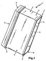
- FIG. 1 shows a filter element 1 with a raw-side upstream side 2 and a clean-side downstream side 3.
- the filter element is formed by a multi-folded filter medium 14, wherein the folds between the upstream side and the downstream side, ie there are each pleat tips on the upstream side and the downstream side ,
- the non-perfused side surfaces of the filter element 4 are in particular surrounded by a polyester fleece, which is provided on its side facing the filter element with a hot melt adhesive layer formed in particular with the hot-melt adhesive according to the invention.
- This hot melt adhesive layer produces a surface bonding of the polyester fleece to the filter element, the front side 5 of the filter bellows also being sealed off.
- the filter element 1 comprises a main frame 6 and an auxiliary frame 7, wherein the main frame carries an axial seal 8, which seals in the direction of the downstream side 3 and is inserted into a groove of the main frame or in a groove between the main frame and side surfaces 4.
- the subframe is connected to the side surfaces 4 by an adhesive connection and has radial surfaces 9 and axial surfaces 10 for supporting the filter element in a housing, not shown.
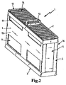
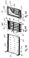
- FIG. 2 shows an embodiment of a filter element 1 with a raw-side upstream side 2 and a clean-side downstream 3.
- a plastic frame 16 is applied by means of a particular formed with the hot melt adhesive melt adhesive according to the invention, wherein on the end faces 5 by the hot melt adhesive also the sealing of the front side takes place.
- On the end sides 15 openings in the plastic frame 16 are introduced.
- the plastic frame 16 carries on the upstream side 2, an axial seal 12, which is engageable with a sealing surface of a housing, not shown.
- a handle 13 provided, which is in communication with the plastic frame 16 and for better handling of the filter element 1 is used.
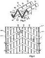
- FIG. 3 shows the detailed view of an arrangement of different traces of adhesive on a filter element according to the invention.
- stabilizing traces 101 are introduced into the folds, in particular from the hot-melt adhesive according to the invention, which extend between fold tips 102 and fold bottom 103.
- 105 stabilization traces 101 are introduced both on the clean side 104 and on the raw side.
- At least two, in particular continuous, stabilizing tracks 101 are applied to the filter medium 106 parallel to one another and perpendicular to the direction of the folded edges 102, 103 before the individual folds are set up.
- the particular otherwise continuous stabilizing traces 101 are interrupted in particular at regular intervals by an interruption 107.
- the adhesive trace is once interrupted between fold tip and wrinkle bottom.
- the interruption 107 is located centrally between the fold tip and wrinkle bottom and corresponds in length between one third and half of the fold height.
- the interruption 107 begins at a distance b from the raw-side fold bottom 103.
- the wrinkles are bonded on the raw side only in the area of the fold bottom and the fold tips.
- an interruption of the adhesive trace over a length a is provided, which surrounds the raw-side fold tip.
- the wrinkles are not glued on the raw side in the area of the pleat tips.
- the distances a and b of roh wornem wrinkle bottom and pure-side pleat tip are formed so that the interruption 107 of the clean side and the raw side adhesive track do not overlap. This ensures that an overlap of the clean-side 104 and raw-side 105 adhesive trace 101 is formed both in the region of the pure-side pleat tips and in the vicinity of the purely-sided pleat base.
- the straight lines x and y formed by the start and end points of the individual adhesive trace portions are parallel to the fold edges.
- uninterrupted sealing marks 201 on the raw side and, optionally, uninterrupted sealing traces 202 on the clean side are provided on the front side, which are provided on the clean side Setting up the folds the pleated folds so closes laterally to form a folding pocket, that raw and clean side of the filter element are sealingly separated from each other.
- the clean-side sealing traces 202 are not absolutely necessary with respect to the separation of raw and clean side, but advantageous in terms of the stability of the filter element.
- FIG. 4 shows an alternative arrangement of adhesive in particular formed with the hot melt adhesive according to the invention on a filter element according to the invention, wherein the illustration shows the filter media web in a flat, unfolded state.
- the start and end points of the interruptions of the stabilizing tracks 101 are aligned on a plurality of straight lines z, which run parallel to one another and form with the folding edges F an angle ⁇ of 10-80 °, preferably 45 +/- 15 °.
- the starting and ending points of the interruptions of the stabilizing tracks extend at least two straight lines z 'and z ", each straight line comprising mutually parallel straight lines, the corresponding straight lines intersecting on the filter medium, whereby an arrow-shaped or zigzag-shaped course of the interruptions 107 of the stabilizing track 101 is formed on the filter medium.
- Raw-side sealing traces 201 run along the end edges 203 of the filter medium in such a way that the sealing tracks when setting up the folds closes them laterally to form a fold pocket such that the raw and clean sides of the filter element are sealingly separated from one another ,
- FIG. 5 an embodiment of the sequence of a method according to the invention for producing a hot melt adhesive system is shown.
- the hardening of the hot-melt adhesive track applied before the folds are set up can take place in such a way, in particular after the folding of the bellows, that gluing of the wrinkles through the applied hot-melt adhesive mixture takes place during hardening.
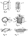
- Fig. 6 shows an embodiment of an annular filter bellows.
- the filter bag 301 is formed from a sheet of a flat filter medium, such as a filter fleece material.
- a flat filter medium such as a filter fleece material.
- rectangular filter material sheets are shaped so that end portions of the sheet 303 nestle against each other.
- Fig. 1 This results in an endless filter bellows 3022, wherein the end portions 303 are held by a sealing track 305 of the hot melt adhesive, which extends between the end portions 303 of the sheet.
- the sealing track 5 is shown in phantom.
- the filter bellows 301 can be introduced, for example, in a filter device into a filter pot, so that the fluid to be filtered, such as fuel, oil or air can pass through the filter medium and is thereby cleaned.
- the sealing track 305 connects over the entire length L or in the representation of Fig. 1 over the entire height, the respective two interconnected end portions fluid-tight.
- Fig. 7 shows a perspective view of another embodiment, wherein an annular filter bellows 310 is formed for a filter element of a zigzag folded filter material.
- the zigzag-shaped filter material is formed into a bellows 302 by connecting end portions or end-fold portions 303 to each other through the seal track 305.
- the zigzag-shaped folding results in a larger surface of the filter material in the filter bellows 310.
- the connection of the end sections 303 of the flat filter material is shown in more detail in the following figures.
- Fig. 8 is a cross section of in Fig. 7 shown embodiment of a filter bellows for a filter element.
- Fig. 8 Looking at the fold profile in the orientation of the Fig. 7 from above or below on the bellows.
- convolutions 306 and 315 each result in opposite orientation.
- the two Endfaltenabête 3031, 3032 are connected and sealed by the sealing track 305. From the interior of the bellows can escape through the interconnected end portions 3031, 3032 no fluid.
- the interconnected end portions 3031, 3032 are pressed, while the sealing track of hot melt adhesive is still liquid, preferably until the hot melt adhesive hardens.
- the pressing is preferably carried out by means of profiled profiles or pliers, which have, for example, a parallel to the Endfaltenabroughen extending, wavy or serrated profiling.
- profiled profiles or pliers which have, for example, a parallel to the Endfaltenabroughen extending, wavy or serrated profiling.
- correspondingly deformed end sections 3031, 3032 are formed as shown in the figure, and a more stable connection is produced.
- the zigzag-shaped filter material sheet is bent over so that the two Endfaltenabête 3031, 3032 lie flat on one another.
- the end edges 3041, 3042 form a common end edge.
- Fig. 9 shows a filter element 311, for example, as an oil or fuel filter, which is designed with a filter element 310 as described above.
- the filter element or the fuel filter 311 comprises a bellows 302, 310 formed of zigzag-shaped filter material, which is held between two covers 312, 313.
- the bellows corresponds to a filter element 310, in which two end sections are fluid-tightly connected to one another by the sealing track 305.
- the upper lid 313 is provided with a port 316 having an opening 317.
- fluid to be filtered can enter the interior of the bellows 310 in the direction of the arrow A, flow through the folds of the filter material and leave the filter element 311 through the opening 317 in the direction of the arrow B.
- a flow in the opposite direction is conceivable.
- the filter element can be introduced into a filter pot or a square bellows can be formed.
- the sealing track 305 is in each case in tight connection with the covers 312, 313, so that a reliable seal between raw and clean side takes place.
- the ends of the sealing track 305 are embedded in the lid, in the case of a glued to the filter bellows 302, 320 lid, the ends of the sealing track 305 in the adhesive layer embedded between the lid and filter bellows or connected to this.
- FIGS. 10, 11 serve to explain variants of the manufacturing process for corresponding filter elements.
- a sheet of filter material sheet 302 is provided.
- the filter material sheet 302 is rectangular in shape.
- the opposite end portions 3031, 3032 are to be connected together to form a tubular filter element body.
- the end edges 3041, 3042 are placed next to each other in the sequence.
- the Filter material sheet first pleated or folded. This is in Fig. 11 shown.
- Various methods for zigzag folding of filter materials are known. It can z. B. counter-folding blades are used to cause the folds of different orientation 306, 315 in the filter sheet. Also rotating knife assemblies are known.
- FIG. 12 a method for producing a filter body according to the invention is shown with mutually closed channels.
- a smooth layer 401 and a corrugated layer 402 of a web-shaped filter material are placed on each other to form a semifinished product.
- an uninterrupted sealing track 403 of liquid hotmelt adhesive between smooth layer 401 and corrugated layer 402 is metered onto the smooth layer along an end edge 408 of the smooth layer 401 by means of a nozzle 409.
- closure stopper 406 by the sealing track, which closes the channels formed between the smooth layer and corrugated layer on one side fluid-tight.
- a flat adhesive trace 404 of hotmelt adhesive is additionally applied, which does not close any channels, but produces a bond between the smooth layer 401 and the corrugated layer 402.
- the semi-finished product thus formed is then provided along the second, the first opposite end edge 410 with a further sealing track 405 and then wound in particular around a core 407, which in turn creates channels which are closed by sealing plugs.
- a flow through the channels along the winding axis 411 is thus only possible by passing into a closed end by plug 406 channel 412 incoming fluid through a filter media layer (smooth or corrugated layer) in a start-side sealed channel 413, whereby the fluid is purified.
- FIG. 13A An alternative way to form a z. B. in the flow direction 415 through-flow filter element of the aforementioned semifinished product is in Fig. 13A shown in which the semi-finished in sections analogous to Zig. 12 is glued to each other.
- the filter element is provided on a flow-through surface with a seal 414 for the separation of raw and clean side in a filter housing.
- FIG. 13B again, that is after Fig. 12 available wound filter body used.
- the same features are identified by the same reference numerals.
- FIG. 14 AC an inventive method for producing a filter element 510 according to the invention is shown.
- a web 501 of flat filter medium is preferably already provided with filter media, which require this, for example by rolling with predetermined folding edges 502, 504, z. B. by pressing transversely to the web and feed direction 511 or by welding along the desired folding edges of single or multi-layered, synthetic media, eg. As nonwovens and / or tissue and / or networks, for. B. from thermoplastic fibers, in particular meltblown fibers.
- adhesive traces are applied from hot melt adhesive.
- the wrinkles are set up, see Fig. 14B whereby the sealing traces between two folded edges 504 come into sealing contact over the pleat height h and seal the end faces 5033 and 5034 in such a manner that the raw side 512 is separated from the clean side 513.
- This distance track can additionally be used as a fastening means for a pre-separation stage, in particular a planar pre-separation fleece 508 arranged just on the inflow side, when this is laid on, as long as the distance lane is still liquid or at least can still produce adhesive bonds.
- further adhesive tracks can be applied parallel in the plane which is the same distance from the distance track, in particular along and in the region of the end faces 5033 and 5034, eg. In one Distance not more than 10 cm, preferably 5 cm from the sealing marks towards the center, for the connection of the pre-separating fleece 508 to be subsequently placed.
- Fig. 14C shows a view of a particular filter element according to the invention 510 with a Vorabscheidervlies 508 on the raw side 512, which is surrounded by a seal 509, which serves for sealing installation in a only two-dimensionally shown in two-dimensional filter housing 520.
- the Vorabscheidervlies 508 is shown cut out in sections are the spacer track 506 and the Vorvliesbefest Trentsspur 507 recognizable.
- the flow can also take place in the opposite direction, in this case, a Vorabscheidervlies on the side facing away from the seal 509 side should be attached as described.
- FIG. 15 shows a produced by a particular method according to the invention side band of two sections 6011, 6012, which are connected by means of a preferably applied by means of slot die, wide adhesive trace 6013 from the used according to this invention hot melt adhesive system.
- the adhesive trace is in particular uninterrupted in the region of the overlap.
- the use of this hot melt adhesive has the advantage that when closing the application nozzles significantly less hot melt adhesive threads.
- Fig. 16 shows a means of two sidebands 601 laterally, perpendicular to the folded edges 504 completed filter element 610 from a folded filter media web.
- the sidebands are in particular according to a method described in the previous section (s. Fig. 15 ) connected by sections.
- the sidebands are in particular made of textile, plastic fabric, plastic mesh, in particular expanded metal mesh, or fleece, in particular thermoplastic fibers, in particular meltblown fibers.
- the width of the adhesive adhesive track is at most as wide as the sideband 601 and does not protrude beyond its edges.
- side surfaces of the side band 601 as sealing surfaces in a filter housing, in particular of a cabin air filter system, in particular for the filtration of indoor air of road vehicles, agricultural and construction machinery.
- another sealing side band 6011 may be provided across the first side bands 601 along the creasing edges, likewise with a continuous hot melt adhesive trace (sealing trace) 605 spanning substantially at least the pleat height h from the hot melt adhesive used in accordance with this invention at the end of FIG Lane 501 attached.
- a polyester hotmelt adhesive (Sika SikaMelt 9120) having a density of 1.25 g / cm 3 and an elongation at break of in the range of 75-115% and a polyamide hot melt adhesive (Henkel Marcomet 6208) having a density of 0.98 g / cm 3 are each heated separately to the processing temperature (200 ° C) with mixing.
- the yarn tension is qualitatively determined so that a 1 mm thick metal rod dipped into the melt and pulled out jerkily.
- a drop of hot melt adhesive remains on the metal round bar, on which a melt adhesive thread remains directly when it is withdrawn from the melt, which cools and hardens. A remaining, solidified thread is visible.
- the thread tension tendency is therefore judged to be high. Furthermore, the granules of the two mentioned hotmelt adhesives are mixed and the mixed granules are heated to 200 ° C and melted together. Immediately thereafter, in order to keep the segregation low, an order is made by means of a directly coupled with a gear pump application nozzle on a flat filter medium. In this case, surprisingly, a lower formation of filaments than in the use of the two hot melt adhesives in a separate form observed. Also, the yarn tension of the hot melt adhesive composition is assessed qualitatively, such that a 1 mm thick metal round bar in the before again in a heated to working temperature porcelain bowl dynamically mixed melt is dipped and pulled out jerkily. There remains a drop of hot melt adhesive on the metal bar into which the thread formed directly after pulling the metal bar back out of the melt retreats. A remaining thread is not recognizable. The thread tension tendency is therefore judged to be low.
- a polyester hot melt adhesive having a melting point at 150-160 ° C, essentially formed from 40% by weight of butanediol, 33% by weight of terephthalic acid, 27% by weight of adipic acid and a polyamide hot melt adhesive having a melting point at 130 ° C. from 67% by weight of ⁇ -caprolactam, 5% by weight of 2,2,4-trimethylhexamethylenediamine, 12% by weight of 1-amino-3-aminomethyl-3,5,5-trimethylcyclohexane and 16% by weight of adipic acid in granule form and mixed together melted with dynamic mixing.
- the yarn tension is qualitatively determined so that a 1 mm thick metal rod dipped into the melt and pulled out jerkily.
- Example 2 a drop of hot melt adhesive remains on the metal bar, into which the thread formed directly after pulling the metal bar out of the melt retreats. A remaining thread is not recognizable. The thread tension tendency is therefore judged to be low.
- the polyester hotmelt adhesive (Sika Sikamelt 9420) with an elongation at break of about 50-60% is obtained in proportions by weight 60:40, 65:35, 70:30 (the polyester hotmelt adhesive is first mentioned in each case) with a polyamide hotmelt adhesive (Henkel Macromet 6208) with a melting temperature between 188 and 195 ° C and a density of 1.02 g / cm 3 as in Example 1 mixed and checked for thread tension tendency.
- a polyamide hotmelt adhesive Heenkel Macromet 6208
- Example 3 a drop of hot melt adhesive remains on the metal rod into which the thread formed directly after the metal rod has been withdrawn from the melt retreats completely or partially, depending on the mixing ratio. The effect is significantly less pronounced than in the application of the two hot melt adhesives in separate use.
- the polyester hotmelt adhesive from Example 2 and a polyamide hotmelt adhesive having a density of 0.97 g / cm 3 , a softening point of 190-205 ° C. are obtained in proportions by weight 30:70, 50:50 and 70:30 analogously to Example 1 mixed and tested.
- a drop of hot melt adhesive remains on the metal bar into which the thread formed directly after the withdrawal of the metal rod from the melt retreats. A remaining thread is not recognizable or significantly less pronounced than in the application of the two hot melt adhesives in separate use wherein from a weight fraction of 70% of said polyester adhesive, the thread tension tendency increases again. The thread tension tendency is therefore judged to be low.
Landscapes
- Chemical & Material Sciences (AREA)
- Chemical Kinetics & Catalysis (AREA)
- Engineering & Computer Science (AREA)
- Textile Engineering (AREA)
- Physics & Mathematics (AREA)
- Geometry (AREA)
- Filtering Materials (AREA)
- Filtering Of Dispersed Particles In Gases (AREA)
- Adhesives Or Adhesive Processes (AREA)
- Combustion & Propulsion (AREA)
- Mechanical Engineering (AREA)
- General Engineering & Computer Science (AREA)
Claims (19)
- Élément filtrant comprenant un corps de filtre constitué d'au moins une couche d'un milieu filtrant plat en forme de bande qui sépare un côté brut d'un côté pur, p. ex. un soufflet de filtre plié en accordéon, le corps de filtre étant collé au moyen d'un système de colles thermofusibles, le système de colles thermofusibles comprenant un mélange de colles thermofusibles, le mélange de colles thermofusibles comprenant 15 à 85 % en poids, en particulier 30 à 70 % en poids, d'une première colle thermofusible à base de polyester, et 15 à 85 % en poids, en particulier 30 à 70 % en poids, d'une deuxième colle thermofusible à base de polyamide, le pourcentage en poids de la première et de la deuxième colles thermofusibles représentant un total de 100 % en poids du mélange de colles thermofusibles, le mélange de colles thermofusibles représentant une part de plus de 75 % en poids du système de colles thermofusibles, le reste étant constitué de matières de charge telles que de la craie et/ou des pigments tels que du dioxyde de titane en tant que pigment blanc et/ou d'une résine rendant adhésive et/ou d'au moins une autre colle thermofusible à base de polycondensat, le corps de filtre présentant sur au moins une surface du milieu filtrant plat en forme de bande un cordon de colle d'étanchéité ininterrompu issu du système de colles thermofusibles qui colle le corps de filtre de telle manière que le côté brut et le côté pur de l'élément filtrant soient séparés l'un de l'autre de façon étanche.
- Élément filtrant selon la revendication 1, caractérisé en ce que le corps de filtre est d'une forme annulaire et constitué d'un soufflet de filtre plié en accordéon à partir d'une feuille de milieu filtrant plate qui est fermée de façon annulaire et étanche aux fluides de telle manière que deux sections d'extrémité situées face à face de la feuille de milieu filtrant soient reliées de manière étanche, en particulier parallèlement aux bords de pliage, par le biais d'un cordon de colle issu du système de colles thermofusibles et disposé le long des bords d'extrémité sur les sections d'extrémité.
- Élément filtrant selon la revendication 2, caractérisé en ce que les sections d'extrémité sont pressées sur le cordon de colle, en particulier avec un profil ondulé.
- Élément filtrant selon les revendications 2 à 3, caractérisé en ce que le cordon de colle est disposé tout au long des bords d'extrémité.
- Élément filtrant selon les revendications 2 à 4, caractérisé en ce que des disques d'extrémité sont disposés sur les faces frontales axiales du corps de filtre de forme annulaire et obturent les faces frontales de manière étanche de sorte que le côté brut soit séparé du côté pur, le cordon de colle étant relié de manière étanche aux disques d'extrémité.
- Élément filtrant selon la revendication 1, caractérisé en ce que le corps de filtre est constitué d'un demi-produit fait de deux couches superposées d'un milieu filtrant, l'une de ces couches étant exécutée en tant que couche plate et la deuxième couche étant exécutée en tant que couche ondulée, le demi-produit étant enroulé ou empilé par couches superposées, de sorte que des canaux de passage soient formés entre les couches, les deux couches étant reliées entre elles respectivement par le biais d'au moins un cordon de colle ininterrompu issu du système de colles thermofusibles, le cordon de colle étant disposé entre la couche lisse et la couche ondulée, verticalement aux ondulations, sur un côté plan de la couche lisse le long d'un premier bord de la couche lisse et le long d'un bord de la couche ondulée, de telle manière que les canaux de passage soient obturés de manière étanche à une première extrémité.
- Élément filtrant selon la revendication 6, caractérisé en ce qu'un deuxième cordon de colle ininterrompu issu du système de colles thermofusibles est prévu, par le biais duquel les deux couches sont reliées entre elles, le deuxième cordon de colle étant disposé entre la couche lisse et la couche ondulée, verticalement aux ondulations, sur le deuxième côté situé en face du premier côté plan de la couche lisse, le long d'un deuxième bord situé en face du premier bord de la couche lisse, de telle manière que les canaux de passage soient obturés de manière étanche à une deuxième extrémité, de manière à ce qu'un corps de filtre présentant des canaux obturés en alternance soit formé.
- Élément filtrant selon la revendication 1, 6 ou 7, caractérisé en ce que le corps de filtre est constitué d'un demi-produit fait de deux couches enroulées superposées d'un milieu filtrant, l'une de ces couches étant exécutée en tant que couche plate et la deuxième couche étant exécutée en tant que couche ondulée, de sorte que des canaux de passage soient formés entre les deux couches, les deux couches étant reliées entre elles par le biais d'au moins un cordon de colle issu du système de colles thermofusibles, le cordon de colle étant disposé en travers, sur un côté orienté vers les sommets des ondulations de la couche lisse, en particulier verticalement aux ondulations, de telle manière que les sommets des ondulations appliqués contre la couche lisse soient collés sur la couche lisse, la hauteur du cordon de colle étant inférieure à la hauteur des ondulations, de sorte que les canaux de passage ne soient pas obturés par ce cordon de colle.
- Élément filtrant selon la revendication 1, caractérisé en ce que le corps de filtre est constitué d'un soufflet de filtre plié en accordéon à partir d'une feuille de milieu filtrant plate, respectivement un cordon de colle ininterrompu issu du système de colles thermofusibles étant prévu le long des bords frontaux de la feuille de milieu filtrant évoluant verticalement aux bords de pliage, ce cordon de colle ininterrompu obturant latéralement les plis dressés en formant une poche de pli de manière à ce que le côté brut et le côté pur de l'élément filtrant soient séparés l'un de l'autre de manière étanche.
- Élément filtrant selon la revendication précédente, caractérisé en ce que les bords de pliage forment un plan sur au moins un côté du soufflet de filtre.
- Élément filtrant selon la revendication précédente, caractérisé en ce qu'un plan formé par les bords de pliage est entouré d'un joint qui encercle le plan et qui est constitué en particulier d'une mousse polymère, en particulier de polyuréthane, pour séparer de manière étanche le côté brut du côté pur dans un boîtier de filtre.
- Élément filtrant selon la revendication 1, en particulier selon la revendication 10 ou 11, caractérisé en ce que le corps de filtre est constitué d'un soufflet de filtre plié en accordéon à partir d'une feuille de milieu filtrant plate, le soufflet de filtre présentant un cordon de colle qui est appliqué, dans un plan du soufflet de filtre formé par les bords de pliage, de façon ininterrompue sur plusieurs de ces bords de pliage, en particulier verticalement aux bords de pliage, en particulier pour stabiliser le soufflet de filtre et maintenir à un niveau constant, durant le fonctionnement, la distance entre les bords de pliage voisins.
- Élément filtrant selon l'une des revendications 1 ou 10 à 12, caractérisé en ce que le corps de filtre est constitué d'un soufflet de filtre plié en accordéon à partir d'une feuille de milieu filtrant plate, avec des bords de pliage du côté entrée et des bords de pliage du côté sortie, et qui comprend une couche de pré-séparateur, constituée en particulier d'un non-tissé, qui repose sur la surface formée par les bords de pliage du côté entrée, le corps de filtre étant collé sur la couche de pré-séparateur au moyen du système de colles thermofusibles, en particulier au moyen de points de colle ou de cordons de colle, en particulier au moyen d'au moins deux cordons de colle, conformément à la revendication 12.
- Élément filtrant selon la revendication 1 ou 10 à 13, caractérisé en ce que le corps de filtre est constitué d'un soufflet de filtre plié en accordéon à partir d'une feuille de milieu filtrant plate, les bords frontaux en accordéon de la feuille de milieu filtrant formant deux faces frontales, une bande latérale faite d'un tissu ou d'un non-tissé étant appliquée sur au moins une des faces frontales, cette bande latérale étant collée en particulier au moyen d'un cordon de colle plan et large issu du système de colles thermofusibles de telle manière que la bande latérale soit collée de manière étanche sur la face frontale au moyen du cordon plan et large, de sorte que le côté brut soit séparé du côté pur.
- Élément filtrant selon l'une des revendications 9 à 14, comprenant un milieu filtrant plié en accordéon qui sépare un côté brut d'un côté pur et qui présente en alternance des crêtes de pli et des creux de pli, des cordons de stabilisation issus du système de colles thermofusibles, qui s'étendent en alternance entre les crêtes de pli et les creux de pli, étant situés dans les interstices de pliage, respectivement au moins deux cordons de colle étant disposés sur l'élément filtrant, aussi bien sur le côté brut que sur le côté pur du milieu filtrant, et ce parallèlement l'un par rapport à l'autre et en particulier verticalement au sens des bords de pliage, les cordons de colle étant interrompus à des distances régulières sur le côté brut et/ou sur le côté pur, les points de départ et les points finaux des interruptions des cordons de colle étant alignés sur une multitude de lignes droites.
- Élément filtrant selon l'une des revendications précédentes, le pourcentage global d'acide adipique dans les substances de base de la première colle thermofusible à base de polyester et de la deuxième colle thermofusible à base de polyamide correspondant à > 5 % en poids, de préférence à > 10 % en poids, et plus spécialement à > 15 % en poids, et en même temps à < 35 % en poids, de préférence à < 30 % en poids, et plus spécialement à < 25 % en poids.
- Procédé de fabrication d'un élément filtrant selon l'une des revendications précédentes, ce procédé comprenant les étapes suivantes :a. fusion d'une première colle thermofusible en particulier exclusivement à base de polyester et d'une deuxième colle thermofusible en particulier exclusivement à base de polyamide,b. en particulier mélange dynamique des deux colles thermofusibles, en particulier en générant des forces de cisaillement dans la matière fondue,c. application du mélange fondu de colles thermofusibles sur un milieu filtrant en forme de bande sous forme d'au moins un cordon de colle ininterrompu avec un effet d'étanchéité et issu du système de colles thermofusibles, sur au moins une surface du milieu filtrant plat en forme de bande, en particulier au moyen d'une buse d'application, de sorte que le corps de filtre soit collé de manière à ce que le côté brut et le côté pur de l'élément filtrant soient séparés l'un de l'autre de manière étanche,d. durcissement du cordon de colle, au nombre d'au moins un, en reliant des sections d'une bande de milieu filtrant du milieu filtrant à d'autres sections de la même bande de milieu filtrant ou à des sections d'une deuxième bande de milieu filtrant, ondulée en particulier, et/ou à un non-tissé du pré-séparateur.
- Procédé selon la revendication précédente, caractérisé en ce que les deux colles thermofusibles, se présentant en particulier sous forme de poudre ou de granulats, sont mélangées avant d'être chauffées, puis sont chauffées et fondues.
- Utilisation d'une colle thermofusible issue d'un système de colles thermofusibles pour le collage d'éléments filtrants selon la revendication 1 au moyen de cordons de colles thermofusibles, le système de colles thermofusibles comprenant un mélange de colles thermofusibles, le mélange de colles thermofusibles comprenant 15 à 85 % en poids, en particulier 30 à 70 % en poids, d'une première colle thermofusible à base de polyester, et 15 à 85 % en poids, en particulier 30 à 70 % en poids, d'une deuxième colle thermofusible à base de polyamide, le pourcentage en poids de la première et de la deuxième colles thermofusibles représentant un total de 100 % en poids du mélange de colles thermofusibles, le mélange de colles thermofusibles représentant une part de plus de 75 % en poids, en particulier de plus de 85 % en poids, et plus spécialement de plus de 95 % en poids du système de colles thermofusibles, le reste étant constitué de matières de charge telles que de la craie et/ou des pigments tels que du dioxyde de titane en tant que pigment blanc et/ou d'une résine rendant adhésive et/ou d'au moins une autre colle thermofusible à base de polycondensat.
Applications Claiming Priority (1)
| Application Number | Priority Date | Filing Date | Title |
|---|---|---|---|
| PCT/EP2012/051254 WO2013110335A1 (fr) | 2012-01-26 | 2012-01-26 | Élément filtrant et procédé de fabrication d'un élément filtrant |
Publications (2)
| Publication Number | Publication Date |
|---|---|
| EP2806962A1 EP2806962A1 (fr) | 2014-12-03 |
| EP2806962B1 true EP2806962B1 (fr) | 2016-03-30 |
Family
ID=45592338
Family Applications (1)
| Application Number | Title | Priority Date | Filing Date |
|---|---|---|---|
| EP12703731.5A Active EP2806962B1 (fr) | 2012-01-26 | 2012-01-26 | Élément filtrant et procédé de fabrication d'un élément filtrant |
Country Status (4)
| Country | Link |
|---|---|
| US (1) | US9669341B2 (fr) |
| EP (1) | EP2806962B1 (fr) |
| CN (1) | CN104066490B (fr) |
| WO (1) | WO2013110335A1 (fr) |
Families Citing this family (12)
| Publication number | Priority date | Publication date | Assignee | Title |
|---|---|---|---|---|
| CN104165106A (zh) * | 2014-06-30 | 2014-11-26 | 赖昭文 | 方便清洗的空气滤芯 |
| US20160030874A1 (en) * | 2014-08-04 | 2016-02-04 | Todd John Shafer | Air filter assembly |
| USD792957S1 (en) * | 2015-02-10 | 2017-07-25 | Blake Starkenburg | Vaporizing device outer lid and basket assembly |
| JP6029701B2 (ja) * | 2015-03-13 | 2016-11-24 | 大紀商事株式会社 | 抽出用シート、抽出用フィルターおよび抽出用バッグ |
| TWI534006B (zh) * | 2015-04-09 | 2016-05-21 | Filter element and its forming method | |
| CN104958968B (zh) * | 2015-05-26 | 2017-09-29 | 杭州南方环境净化设备有限公司 | 扁形滤筒及其制造方法 |
| WO2018075385A1 (fr) | 2016-10-20 | 2018-04-26 | Cummins Filtration Ip, Inc. | Gaufrage directionnel interrompu de feuille plate |
| US10914228B2 (en) | 2016-11-15 | 2021-02-09 | Cummins Inc. | Waste heat recovery with active coolant pressure control system |
| DE102016015062A1 (de) * | 2016-12-19 | 2018-06-21 | Mann + Hummel Gmbh | Filterelement, insbesondere zur Gasfiltration |
| WO2020112482A1 (fr) * | 2018-11-29 | 2020-06-04 | Cummins Filtration Ip, Inc. | Cadre de filtre multicouche amélioré |
| DE112020006342T5 (de) * | 2019-12-26 | 2022-10-20 | Cummins Filtration Inc | Filterelement mit strömungleitenden durchlässigkeitsschichten |
| CN113041715B (zh) * | 2021-03-11 | 2022-07-19 | 清远华滤环保设备有限公司 | 过滤件加工设备及过滤件加工方法 |
Family Cites Families (24)
| Publication number | Priority date | Publication date | Assignee | Title |
|---|---|---|---|---|
| DE1299230B (de) | 1966-12-24 | 1969-07-10 | Draegerwerk Ag | Verfahren zum Herstellen eines Schwebstoffiltereinsatzes aus gefaltetem Filtermaterial fuer Schwebstoffilter von Atemschutzgeraeten |
| US4217435A (en) * | 1976-12-02 | 1980-08-12 | Eastman Kodak Company | Adhesive composition |
| JPS6017359B2 (ja) * | 1978-09-20 | 1985-05-02 | 旭化成株式会社 | ポリエステル系ホツトメルト接着剤 |
| US5236480A (en) * | 1989-01-05 | 1993-08-17 | Camfil Ab | Air filter for workstations and methods of making and using such air filter |
| DE4430333C2 (de) * | 1994-08-29 | 2000-02-17 | Mann & Hummel Filter | Filter |
| US5783086A (en) * | 1995-09-29 | 1998-07-21 | W. L. Gore & Associates, Inc. | Filter for a wet/dry vacuum cleaner for wet material collection |
| AU1593599A (en) * | 1998-01-08 | 1999-07-26 | H.B. Fuller Licensing And Financing Inc. | Thermoplastic compositions comprising crystalline water soluble polymers and amorphous water sensitive polymers |
| CN2352239Y (zh) * | 1998-08-18 | 1999-12-08 | 江南造船(集团)有限责任公司 | 烟尘气过滤用滤芯 |
| US6926781B2 (en) * | 2002-03-14 | 2005-08-09 | 3M Innovative Properties Company | Continuous filter framing strip storable in roll form |
| ATE424245T1 (de) * | 2002-07-18 | 2009-03-15 | Freudenberg Nonwovens Ltd Part | Filterpack mit vliesstofffiltermedien und vliesstoffrandbindungsrahmen |
| US7258717B2 (en) * | 2004-06-28 | 2007-08-21 | 3M Innovative Properties Company | Filter cross brace |
| US7896940B2 (en) * | 2004-07-09 | 2011-03-01 | 3M Innovative Properties Company | Self-supporting pleated filter media |
| DE102005030431A1 (de) | 2005-06-30 | 2007-01-11 | Henkel Kgaa | Schmelzklebstoff mit Duftstoffen |
| US7708797B2 (en) * | 2006-01-20 | 2010-05-04 | Donaldson Company, Inc. | Air cleaner configured for receipt of various sized filter cartridges; components thereof; and, methods |
| US8328896B2 (en) * | 2006-03-10 | 2012-12-11 | Lpd Technologies, Inc. | Frame for filter pack |
| DE102007034907A1 (de) * | 2007-07-24 | 2009-01-29 | Mann + Hummel Gmbh | Filterelement mit Dichtung und Verfahren zur Herstellung des Filterelements |
| US8673040B2 (en) * | 2008-06-13 | 2014-03-18 | Donaldson Company, Inc. | Filter construction for use with air in-take for gas turbine and methods |
| CN201253524Y (zh) * | 2008-07-26 | 2009-06-10 | 蚌埠市昊业滤清器有限公司 | 蜂窝式空气滤清器滤芯 |
| CN201310731Y (zh) * | 2008-10-31 | 2009-09-16 | 蚌埠捷特威过滤器有限公司 | 机油滤芯 |
| DE102009040202B4 (de) * | 2009-09-07 | 2015-10-01 | Mann + Hummel Gmbh | Filter |
| DE102010032294A1 (de) * | 2010-07-26 | 2012-01-26 | Mann + Hummel Gmbh | Schmelzklebstoff und Verfahren zur Herstellung eines Schmelzklebstoffes |
| DE102010032295A1 (de) * | 2010-07-26 | 2012-01-26 | Mann + Hummel Gmbh | Filterelement und Verfahren zur Herstellung eines Filterelements |
| LT2622035T (lt) * | 2010-09-27 | 2023-06-12 | Henkel Ag & Co. Kgaa | Klijavimas karšto lydalo klijais |
| CN201969424U (zh) * | 2011-01-19 | 2011-09-14 | 康斐尔过滤设备(昆山)有限公司 | 过滤器的滤芯改良结构 |
-
2012
- 2012-01-26 CN CN201280068251.2A patent/CN104066490B/zh not_active Expired - Fee Related
- 2012-01-26 EP EP12703731.5A patent/EP2806962B1/fr active Active
- 2012-01-26 WO PCT/EP2012/051254 patent/WO2013110335A1/fr active Application Filing
-
2014
- 2014-07-28 US US14/444,336 patent/US9669341B2/en not_active Expired - Fee Related
Also Published As
| Publication number | Publication date |
|---|---|
| WO2013110335A1 (fr) | 2013-08-01 |
| US9669341B2 (en) | 2017-06-06 |
| CN104066490A (zh) | 2014-09-24 |
| US20140331627A1 (en) | 2014-11-13 |
| EP2806962A1 (fr) | 2014-12-03 |
| CN104066490B (zh) | 2016-09-14 |
Similar Documents
| Publication | Publication Date | Title |
|---|---|---|
| EP2806962B1 (fr) | Élément filtrant et procédé de fabrication d'un élément filtrant | |
| EP2598227B1 (fr) | Élément filtrant et procédé de fabrication d'un élément filtrant | |
| EP1409106B1 (fr) | Procede de realisation d'une interface de connexion d'un element filtrant | |
| EP3415213B1 (fr) | Élément filtrant | |
| EP0737092B1 (fr) | Procede de fabrication d'une cartouche de filtre | |
| DE69225981T2 (de) | Filtersystem zum filtrieren von fluiden | |
| WO2011113876A1 (fr) | Dispositif de pliage d'un média filtrant sous forme de bande continue et procédé de fabrication d'un élément filtrant plié en accordéon | |
| EP2135662A1 (fr) | Elément filtrant compressible avec des capuchons d'extrémité inclinés les uns vers les autres | |
| EP1862206A1 (fr) | Elément de filtre destiné au nettoyage d'un fluide | |
| WO2022023301A1 (fr) | Elément filtrant et procédé de fabrication d'un élément filtrant | |
| DE102009041401A1 (de) | Filterelement mit einem Filtermedium sowie Verfahren zum Herstellen desselben | |
| WO2007093291A1 (fr) | Element filtrant et agencement | |
| WO2000038820A1 (fr) | Procede pour produire un element filtrant | |
| WO2018059830A1 (fr) | Élément filtre | |
| DE102010024093A1 (de) | Innenraumluftfilterelement, Filteraufnahme, Filteranordnung und Verfahren zum Herstellen des Innenraumluftfilterelements | |
| WO2012019681A1 (fr) | Bande de matière filtrante et élément de filtre réalisé à partir de celle-ci | |
| EP4003570B1 (fr) | Élément filtrant, filtre à air intérieur et procédé de production | |
| WO2016046127A1 (fr) | Élément formant filtre pourvu d'un soufflet de filtre | |
| WO2021063699A1 (fr) | Élément filtrant et procédé de fabrication d'un élément filtrant | |
| EP4277720A1 (fr) | Procédé de formation d'un milieu filtrant | |
| EP2431086A2 (fr) | Filtre à air pour espaces intérieurs et son procédé de fabrication | |
| WO2019016228A1 (fr) | Matériau filtrant, paquet de plis, élément filtrant, procédé de fabrication d'un matériau filtrant et d'un paquet de plis, et procédé de filtration d'un fluide | |
| DE20214975U1 (de) | Flexibler Filter |
Legal Events
| Date | Code | Title | Description |
|---|---|---|---|
| PUAI | Public reference made under article 153(3) epc to a published international application that has entered the european phase |
Free format text: ORIGINAL CODE: 0009012 |
|
| 17P | Request for examination filed |
Effective date: 20140612 |
|
| AK | Designated contracting states |
Kind code of ref document: A1 Designated state(s): AL AT BE BG CH CY CZ DE DK EE ES FI FR GB GR HR HU IE IS IT LI LT LU LV MC MK MT NL NO PL PT RO RS SE SI SK SM TR |
|
| DAX | Request for extension of the european patent (deleted) | ||
| REG | Reference to a national code |
Ref country code: DE Ref legal event code: R079 Ref document number: 502012006500 Country of ref document: DE Free format text: PREVIOUS MAIN CLASS: B01D0039080000 Ipc: B01D0046000000 |
|
| RIC1 | Information provided on ipc code assigned before grant |
Ipc: B01D 39/08 20060101ALI20150730BHEP Ipc: B01D 46/00 20060101AFI20150730BHEP Ipc: F01N 3/022 20060101ALI20150730BHEP Ipc: B32B 37/12 20060101ALI20150730BHEP |
|
| GRAP | Despatch of communication of intention to grant a patent |
Free format text: ORIGINAL CODE: EPIDOSNIGR1 |
|
| GRAP | Despatch of communication of intention to grant a patent |
Free format text: ORIGINAL CODE: EPIDOSNIGR1 |
|
| INTG | Intention to grant announced |
Effective date: 20150923 |
|
| INTG | Intention to grant announced |
Effective date: 20151022 |
|
| GRAS | Grant fee paid |
Free format text: ORIGINAL CODE: EPIDOSNIGR3 |
|
| GRAA | (expected) grant |
Free format text: ORIGINAL CODE: 0009210 |
|
| AK | Designated contracting states |
Kind code of ref document: B1 Designated state(s): AL AT BE BG CH CY CZ DE DK EE ES FI FR GB GR HR HU IE IS IT LI LT LU LV MC MK MT NL NO PL PT RO RS SE SI SK SM TR |
|
| REG | Reference to a national code |
Ref country code: GB Ref legal event code: FG4D Free format text: NOT ENGLISH |
|
| REG | Reference to a national code |
Ref country code: CH Ref legal event code: EP |
|
| REG | Reference to a national code |
Ref country code: AT Ref legal event code: REF Ref document number: 784746 Country of ref document: AT Kind code of ref document: T Effective date: 20160415 |
|
| REG | Reference to a national code |
Ref country code: IE Ref legal event code: FG4D Free format text: LANGUAGE OF EP DOCUMENT: GERMAN |
|
| REG | Reference to a national code |
Ref country code: DE Ref legal event code: R096 Ref document number: 502012006500 Country of ref document: DE |
|
| REG | Reference to a national code |
Ref country code: LT Ref legal event code: MG4D |
|
| PG25 | Lapsed in a contracting state [announced via postgrant information from national office to epo] |
Ref country code: NO Free format text: LAPSE BECAUSE OF FAILURE TO SUBMIT A TRANSLATION OF THE DESCRIPTION OR TO PAY THE FEE WITHIN THE PRESCRIBED TIME-LIMIT Effective date: 20160630 Ref country code: FI Free format text: LAPSE BECAUSE OF FAILURE TO SUBMIT A TRANSLATION OF THE DESCRIPTION OR TO PAY THE FEE WITHIN THE PRESCRIBED TIME-LIMIT Effective date: 20160330 Ref country code: GR Free format text: LAPSE BECAUSE OF FAILURE TO SUBMIT A TRANSLATION OF THE DESCRIPTION OR TO PAY THE FEE WITHIN THE PRESCRIBED TIME-LIMIT Effective date: 20160701 Ref country code: HR Free format text: LAPSE BECAUSE OF FAILURE TO SUBMIT A TRANSLATION OF THE DESCRIPTION OR TO PAY THE FEE WITHIN THE PRESCRIBED TIME-LIMIT Effective date: 20160330 |
|
| REG | Reference to a national code |
Ref country code: NL Ref legal event code: MP Effective date: 20160330 |
|
| PG25 | Lapsed in a contracting state [announced via postgrant information from national office to epo] |
Ref country code: LV Free format text: LAPSE BECAUSE OF FAILURE TO SUBMIT A TRANSLATION OF THE DESCRIPTION OR TO PAY THE FEE WITHIN THE PRESCRIBED TIME-LIMIT Effective date: 20160330 Ref country code: LT Free format text: LAPSE BECAUSE OF FAILURE TO SUBMIT A TRANSLATION OF THE DESCRIPTION OR TO PAY THE FEE WITHIN THE PRESCRIBED TIME-LIMIT Effective date: 20160330 Ref country code: RS Free format text: LAPSE BECAUSE OF FAILURE TO SUBMIT A TRANSLATION OF THE DESCRIPTION OR TO PAY THE FEE WITHIN THE PRESCRIBED TIME-LIMIT Effective date: 20160330 Ref country code: SE Free format text: LAPSE BECAUSE OF FAILURE TO SUBMIT A TRANSLATION OF THE DESCRIPTION OR TO PAY THE FEE WITHIN THE PRESCRIBED TIME-LIMIT Effective date: 20160330 |
|
| PG25 | Lapsed in a contracting state [announced via postgrant information from national office to epo] |
Ref country code: NL Free format text: LAPSE BECAUSE OF FAILURE TO SUBMIT A TRANSLATION OF THE DESCRIPTION OR TO PAY THE FEE WITHIN THE PRESCRIBED TIME-LIMIT Effective date: 20160330 |
|
| PG25 | Lapsed in a contracting state [announced via postgrant information from national office to epo] |
Ref country code: IS Free format text: LAPSE BECAUSE OF FAILURE TO SUBMIT A TRANSLATION OF THE DESCRIPTION OR TO PAY THE FEE WITHIN THE PRESCRIBED TIME-LIMIT Effective date: 20160730 Ref country code: PL Free format text: LAPSE BECAUSE OF FAILURE TO SUBMIT A TRANSLATION OF THE DESCRIPTION OR TO PAY THE FEE WITHIN THE PRESCRIBED TIME-LIMIT Effective date: 20160330 Ref country code: EE Free format text: LAPSE BECAUSE OF FAILURE TO SUBMIT A TRANSLATION OF THE DESCRIPTION OR TO PAY THE FEE WITHIN THE PRESCRIBED TIME-LIMIT Effective date: 20160330 |
|
| PG25 | Lapsed in a contracting state [announced via postgrant information from national office to epo] |
Ref country code: PT Free format text: LAPSE BECAUSE OF FAILURE TO SUBMIT A TRANSLATION OF THE DESCRIPTION OR TO PAY THE FEE WITHIN THE PRESCRIBED TIME-LIMIT Effective date: 20160801 Ref country code: SM Free format text: LAPSE BECAUSE OF FAILURE TO SUBMIT A TRANSLATION OF THE DESCRIPTION OR TO PAY THE FEE WITHIN THE PRESCRIBED TIME-LIMIT Effective date: 20160330 Ref country code: ES Free format text: LAPSE BECAUSE OF FAILURE TO SUBMIT A TRANSLATION OF THE DESCRIPTION OR TO PAY THE FEE WITHIN THE PRESCRIBED TIME-LIMIT Effective date: 20160330 Ref country code: RO Free format text: LAPSE BECAUSE OF FAILURE TO SUBMIT A TRANSLATION OF THE DESCRIPTION OR TO PAY THE FEE WITHIN THE PRESCRIBED TIME-LIMIT Effective date: 20160330 Ref country code: CZ Free format text: LAPSE BECAUSE OF FAILURE TO SUBMIT A TRANSLATION OF THE DESCRIPTION OR TO PAY THE FEE WITHIN THE PRESCRIBED TIME-LIMIT Effective date: 20160330 Ref country code: SK Free format text: LAPSE BECAUSE OF FAILURE TO SUBMIT A TRANSLATION OF THE DESCRIPTION OR TO PAY THE FEE WITHIN THE PRESCRIBED TIME-LIMIT Effective date: 20160330 |
|
| REG | Reference to a national code |
Ref country code: DE Ref legal event code: R097 Ref document number: 502012006500 Country of ref document: DE |
|
| PG25 | Lapsed in a contracting state [announced via postgrant information from national office to epo] |
Ref country code: DK Free format text: LAPSE BECAUSE OF FAILURE TO SUBMIT A TRANSLATION OF THE DESCRIPTION OR TO PAY THE FEE WITHIN THE PRESCRIBED TIME-LIMIT Effective date: 20160330 |
|
| PLBE | No opposition filed within time limit |
Free format text: ORIGINAL CODE: 0009261 |
|
| STAA | Information on the status of an ep patent application or granted ep patent |
Free format text: STATUS: NO OPPOSITION FILED WITHIN TIME LIMIT |
|
| 26N | No opposition filed |
Effective date: 20170103 |
|
| PG25 | Lapsed in a contracting state [announced via postgrant information from national office to epo] |
Ref country code: SI Free format text: LAPSE BECAUSE OF FAILURE TO SUBMIT A TRANSLATION OF THE DESCRIPTION OR TO PAY THE FEE WITHIN THE PRESCRIBED TIME-LIMIT Effective date: 20160330 Ref country code: BE Free format text: LAPSE BECAUSE OF NON-PAYMENT OF DUE FEES Effective date: 20170131 |
|
| REG | Reference to a national code |
Ref country code: CH Ref legal event code: PL |
|
| GBPC | Gb: european patent ceased through non-payment of renewal fee |
Effective date: 20170126 |
|
| PG25 | Lapsed in a contracting state [announced via postgrant information from national office to epo] |
Ref country code: MC Free format text: LAPSE BECAUSE OF FAILURE TO SUBMIT A TRANSLATION OF THE DESCRIPTION OR TO PAY THE FEE WITHIN THE PRESCRIBED TIME-LIMIT Effective date: 20160330 |
|
| REG | Reference to a national code |
Ref country code: FR Ref legal event code: ST Effective date: 20170929 |
|
| PG25 | Lapsed in a contracting state [announced via postgrant information from national office to epo] |
Ref country code: LI Free format text: LAPSE BECAUSE OF NON-PAYMENT OF DUE FEES Effective date: 20170131 Ref country code: CH Free format text: LAPSE BECAUSE OF NON-PAYMENT OF DUE FEES Effective date: 20170131 Ref country code: FR Free format text: LAPSE BECAUSE OF NON-PAYMENT OF DUE FEES Effective date: 20170131 |
|
| REG | Reference to a national code |
Ref country code: IE Ref legal event code: MM4A |
|
| PG25 | Lapsed in a contracting state [announced via postgrant information from national office to epo] |
Ref country code: LU Free format text: LAPSE BECAUSE OF NON-PAYMENT OF DUE FEES Effective date: 20170126 Ref country code: GB Free format text: LAPSE BECAUSE OF NON-PAYMENT OF DUE FEES Effective date: 20170126 |
|
| REG | Reference to a national code |
Ref country code: BE Ref legal event code: MM Effective date: 20170131 |
|
| PG25 | Lapsed in a contracting state [announced via postgrant information from national office to epo] |
Ref country code: IE Free format text: LAPSE BECAUSE OF NON-PAYMENT OF DUE FEES Effective date: 20170126 |
|
| REG | Reference to a national code |
Ref country code: DE Ref legal event code: R081 Ref document number: 502012006500 Country of ref document: DE Owner name: MANN+HUMMEL GMBH, DE Free format text: FORMER OWNER: MANN + HUMMEL GMBH, 71638 LUDWIGSBURG, DE |
|
| PG25 | Lapsed in a contracting state [announced via postgrant information from national office to epo] |
Ref country code: MT Free format text: LAPSE BECAUSE OF FAILURE TO SUBMIT A TRANSLATION OF THE DESCRIPTION OR TO PAY THE FEE WITHIN THE PRESCRIBED TIME-LIMIT Effective date: 20160330 |
|
| PG25 | Lapsed in a contracting state [announced via postgrant information from national office to epo] |
Ref country code: AL Free format text: LAPSE BECAUSE OF FAILURE TO SUBMIT A TRANSLATION OF THE DESCRIPTION OR TO PAY THE FEE WITHIN THE PRESCRIBED TIME-LIMIT Effective date: 20160330 |
|
| PG25 | Lapsed in a contracting state [announced via postgrant information from national office to epo] |
Ref country code: HU Free format text: LAPSE BECAUSE OF FAILURE TO SUBMIT A TRANSLATION OF THE DESCRIPTION OR TO PAY THE FEE WITHIN THE PRESCRIBED TIME-LIMIT; INVALID AB INITIO Effective date: 20120126 |
|
| PG25 | Lapsed in a contracting state [announced via postgrant information from national office to epo] |
Ref country code: BG Free format text: LAPSE BECAUSE OF FAILURE TO SUBMIT A TRANSLATION OF THE DESCRIPTION OR TO PAY THE FEE WITHIN THE PRESCRIBED TIME-LIMIT Effective date: 20160330 |
|
| PG25 | Lapsed in a contracting state [announced via postgrant information from national office to epo] |
Ref country code: CY Free format text: LAPSE BECAUSE OF FAILURE TO SUBMIT A TRANSLATION OF THE DESCRIPTION OR TO PAY THE FEE WITHIN THE PRESCRIBED TIME-LIMIT Effective date: 20160330 |
|
| PG25 | Lapsed in a contracting state [announced via postgrant information from national office to epo] |
Ref country code: MK Free format text: LAPSE BECAUSE OF FAILURE TO SUBMIT A TRANSLATION OF THE DESCRIPTION OR TO PAY THE FEE WITHIN THE PRESCRIBED TIME-LIMIT Effective date: 20160330 |
|
| PG25 | Lapsed in a contracting state [announced via postgrant information from national office to epo] |
Ref country code: TR Free format text: LAPSE BECAUSE OF FAILURE TO SUBMIT A TRANSLATION OF THE DESCRIPTION OR TO PAY THE FEE WITHIN THE PRESCRIBED TIME-LIMIT Effective date: 20160330 |
|
| PGFP | Annual fee paid to national office [announced via postgrant information from national office to epo] |
Ref country code: IT Payment date: 20200131 Year of fee payment: 9 Ref country code: AT Payment date: 20200122 Year of fee payment: 9 |
|
| REG | Reference to a national code |
Ref country code: AT Ref legal event code: MM01 Ref document number: 784746 Country of ref document: AT Kind code of ref document: T Effective date: 20210126 |
|
| PG25 | Lapsed in a contracting state [announced via postgrant information from national office to epo] |
Ref country code: AT Free format text: LAPSE BECAUSE OF NON-PAYMENT OF DUE FEES Effective date: 20210126 |
|
| PG25 | Lapsed in a contracting state [announced via postgrant information from national office to epo] |
Ref country code: IT Free format text: LAPSE BECAUSE OF NON-PAYMENT OF DUE FEES Effective date: 20210126 |
|
| PGFP | Annual fee paid to national office [announced via postgrant information from national office to epo] |
Ref country code: DE Payment date: 20240119 Year of fee payment: 13 |