EP2806446B1 - Interrupteur destiné à la réception d'un actionneur - Google Patents
Interrupteur destiné à la réception d'un actionneur Download PDFInfo
- Publication number
- EP2806446B1 EP2806446B1 EP14169489.3A EP14169489A EP2806446B1 EP 2806446 B1 EP2806446 B1 EP 2806446B1 EP 14169489 A EP14169489 A EP 14169489A EP 2806446 B1 EP2806446 B1 EP 2806446B1
- Authority
- EP
- European Patent Office
- Prior art keywords
- actuator
- switch
- switching unit
- pivoting
- shaft
- Prior art date
- Legal status (The legal status is an assumption and is not a legal conclusion. Google has not performed a legal analysis and makes no representation as to the accuracy of the status listed.)
- Not-in-force
Links
- 230000008878 coupling Effects 0.000 claims description 19
- 238000010168 coupling process Methods 0.000 claims description 19
- 238000005859 coupling reaction Methods 0.000 claims description 19
- 238000003780 insertion Methods 0.000 claims description 4
- 230000037431 insertion Effects 0.000 claims description 4
- 230000004044 response Effects 0.000 claims description 2
- 238000007789 sealing Methods 0.000 description 8
- 230000008901 benefit Effects 0.000 description 4
- 230000000712 assembly Effects 0.000 description 3
- 238000000429 assembly Methods 0.000 description 3
- 230000000694 effects Effects 0.000 description 3
- 238000005192 partition Methods 0.000 description 3
- 238000000926 separation method Methods 0.000 description 3
- 230000009471 action Effects 0.000 description 2
- 230000007246 mechanism Effects 0.000 description 2
- 238000012544 monitoring process Methods 0.000 description 2
- 230000001960 triggered effect Effects 0.000 description 2
- XLYOFNOQVPJJNP-UHFFFAOYSA-N water Substances O XLYOFNOQVPJJNP-UHFFFAOYSA-N 0.000 description 2
- 230000006978 adaptation Effects 0.000 description 1
- 238000005452 bending Methods 0.000 description 1
- 230000000903 blocking effect Effects 0.000 description 1
- 238000010276 construction Methods 0.000 description 1
- 230000001419 dependent effect Effects 0.000 description 1
- 238000001514 detection method Methods 0.000 description 1
- 238000006073 displacement reaction Methods 0.000 description 1
- 230000003628 erosive effect Effects 0.000 description 1
- 239000007788 liquid Substances 0.000 description 1
- 239000000463 material Substances 0.000 description 1
- 230000001681 protective effect Effects 0.000 description 1
- 230000035945 sensitivity Effects 0.000 description 1
- 239000007921 spray Substances 0.000 description 1
- 230000008719 thickening Effects 0.000 description 1
Images

Classifications
-
- H—ELECTRICITY
- H01—ELECTRIC ELEMENTS
- H01H—ELECTRIC SWITCHES; RELAYS; SELECTORS; EMERGENCY PROTECTIVE DEVICES
- H01H27/00—Switches operated by a removable member, e.g. key, plug or plate; Switches operated by setting members according to a single predetermined combination out of several possible settings
-
- H—ELECTRICITY
- H01—ELECTRIC ELEMENTS
- H01H—ELECTRIC SWITCHES; RELAYS; SELECTORS; EMERGENCY PROTECTIVE DEVICES
- H01H1/00—Contacts
- H01H1/12—Contacts characterised by the manner in which co-operating contacts engage
- H01H1/14—Contacts characterised by the manner in which co-operating contacts engage by abutting
- H01H1/20—Bridging contacts
-
- H—ELECTRICITY
- H01—ELECTRIC ELEMENTS
- H01H—ELECTRIC SWITCHES; RELAYS; SELECTORS; EMERGENCY PROTECTIVE DEVICES
- H01H9/00—Details of switching devices, not covered by groups H01H1/00 - H01H7/00
- H01H9/02—Bases, casings, or covers
- H01H9/04—Dustproof, splashproof, drip-proof, waterproof, or flameproof casings
- H01H2009/048—Dustproof, splashproof, drip-proof, waterproof, or flameproof casings using a sealing boot, e.g. the casing having separate elastic body surrounding the operating member and hermetically closing the opening for it
-
- H—ELECTRICITY
- H01—ELECTRIC ELEMENTS
- H01H—ELECTRIC SWITCHES; RELAYS; SELECTORS; EMERGENCY PROTECTIVE DEVICES
- H01H3/00—Mechanisms for operating contacts
- H01H3/32—Driving mechanisms, i.e. for transmitting driving force to the contacts
- H01H3/48—Driving mechanisms, i.e. for transmitting driving force to the contacts using lost-motion device
Definitions
- the invention relates to a switching unit, a switch assembly with a switching unit and a security system for a door, in particular for an elevator door.
- electrical switching units are considered, which perform an electrical switching function in dependence on the position of an associated actuator.
- Such switching units, or switch assemblies formed of switching units and associated actuators can be used for detecting the position of two mechanical elements relative to each other, wherein the switching unit is arranged on one of the elements of the actuator and on the other element, so that in a predetermined receiving position the actuator is received in a receiving area of the switching unit and thereby a switching function is performed.
- switching units and switch assemblies can be used as a safety switch or machine switch, for example.
- a safety switch or machine switch for example.
- a limit switch or door contact In the form of a limit switch or door contact.
- the G 8120 397 shows such a safety switch with a switch housing and a control housing, in which a switch is controlled by the stroke of a moving from the control housing plunger.
- a control roller In the control housing, a control roller is pivotable about a shaft.
- a toggle lever To the control roller and the plunger a toggle lever is articulated so that is raised or lowered at a pivoting of the control roller, the plunger.
- the actuation takes place by an actuating bow, which is inserted through a slot in the control housing, comes into contact with a control wing of the control roller and pivoted on further forward sliding the control roller.
- a blocking wing of the control roller engages in a window of the control bar and serves to ensure the inevitability of the contact operation when pulling out the actuating bracket.
- the publication WO 2012/113102 A1 describes an electrical switch with two spaced electrical contacts.
- An actuator is inserted through an opening in a housing and there caused by engagement with a driver, the rotation of a main shaft.
- a translational force is exerted on a contact holder, through which the contacts are closed.
- engagement with the driver results in rotation in the opposite direction and separation of the contacts.
- a ratchet wheel is rotatably mounted about an axis on a shaft.
- the ratchet is operatively connected to the plunger of a switch via circumferentially positively driven rollers in a cam track of the ratchet wheel.
- the operative connection between plunger and ratchet wheel can also be made by means of a connecting rod.
- the switch with electrical contacts is housed in a closed switching space of the housing into which the plunger is guided.
- the plunger is sealed against the switch room by means of a seal in the region of the passage.
- a frame-like actuator is used for switching the switching wheel.
- a cross bar on the actuator engages in a slot of the switching frame.
- the publication JP 08285183 A concerns a switch, for example on the door of a copier.
- An actuator has an elastic member and an actuator member which comes into contact with a switch.
- the actuator part When closing the door, the actuator part is guided by guides to the switch.
- the elastic part When the door is open, the elastic part prevents damage when exposed.
- the publication DE 295 04 673 U1 relates to an actuator for a safety position switch.
- the actuator engages an insertion channel of the safety position switch with a key element that is resiliently pivotally attached to a mounting member.
- the switching unit according to the invention has a receiving area for receiving an actuator.
- the recording of the actuator is preferably carried out in the form of a translational movement of the actuator in a retraction in the receiving area.
- the receiving area may in principle be open to several sides, but preferred is a receiving chamber enclosed by a housing except for an insertion.
- a pivoting element is arranged and designed such that the receptacle of the actuator in the retraction direction leads to a pivoting movement of the pivoting element.
- the actuator applies to the pivot element and causes the pivoting movement with further retraction. While possible embodiments of the pivoting element will be described in more detail below, it is generally preferred that the pivoting element has at least one part, designed, for example, as a leg, with which the actuator comes into contact when entering the receiving space and thus effects the pivoting movement.
- the switching unit further includes an electrical switch element and a switch actuating element therefor, the electrical switch element closing or interrupting an electrical contact in response to the actuation by the switch actuating element.
- the switch actuating element is displaceable in an actuating direction to effect the actuation of the electrical switch element.
- a propulsion coupling is provided to adjust the switch actuator in the direction of actuation.
- the propulsion coupling is coupled to the pivoting element via a shaft, so that an adjustment of the switch actuating element takes place during the pivoting movement of the pivoting element.
- the inclusion of the actuator in the receiving area causes a pivoting movement of the pivot member, which is transmitted via the shaft to the drive coupling and leads to an adjustment of the switch actuating element in the actuating direction, which in turn actuates the electric Switch element is done.
- the electrical switch element is mechanically coupled via said elements with the pivot member, wherein the proposed type of mechanical coupling brings a number of advantages.
- the proposed type of mechanical coupling brings a number of advantages.
- the only indirect coupling of the movement of the actuator and the movement of the switch operating element a suitable adaptation of operating paths and mechanical tolerances in particular well possible.
- a very accurate guidance and positioning of the switch actuating element is advantageous for a safe electrical switching operation, the movement of the actuator in the receiving area can be reliably detected despite greater mechanical tolerances.
- a Studentsfahrweg be ensured in which after a successful tripping of the switch operation further movement of the actuator in the retraction direction is easily possible.
- the receiving area and the pivoting element can preferably be designed so that a first part of the movement of the actuator leads to the pivoting movement, while the actuator is received in further movement over the first part of addition out in a transit space without the pivot member performs a further pivoting movement ,
- the switching unit can be constructed very compact, in particular with a small overall depth in the retraction direction. This can be achieved particularly well when the actuating direction is arranged parallel to the retraction direction, and the switch actuating element is spaced transversely to the actuating direction of the receiving area.
- the parallel arrangement with a coupling via the shaft then allows a very short switching unit in the retraction direction.
- the switching unit has a propulsion chamber for receiving the propulsion coupling.
- the propulsion chamber is separated from the necessarily open receiving area by a wall which is penetrated only by the shaft. In this case, already by appropriate fit a first sealing function can be realized, further sealing measures can be easily additionally provided on the shaft.
- a separate switch chamber may be provided for receiving the switch element. Also between the propulsion chamber and the switch chamber is preferably a chamber wall formed with an opening for the switch actuator.
- a sealing function can already be achieved by appropriate fitting, preferably an additional sealing element is provided, for example as an O-ring or particularly preferably as a bellows.
- the pivoting member is formed so that the retraction of the actuator into the receiving area leads to a pivoting movement in a first pivoting direction, and that the extension of the actuator out of the receiving area leads to a pivoting movement in a second, opposite direction.
- the pivoting element have at least one first leg for contact with the actuator in the retraction direction, and a second leg for contact with the actuator during extension.
- a positive reception is particularly preferably given after the retraction of the actuator and the pivoting movement of the pivoting element, so that the retraction of the actuator inevitably leads to the pivoting movement in the second pivoting direction.
- said legs may protrude radially from the shaft, wherein, for example, the first and the second leg are at an angle to each other, preferably at 90 °.
- the actuator may have a shaft which extends, for example, rod-shaped in the retraction direction, and a head which is shaped differently from the shaft and in particular may preferably have at least one step for the positive reception.
- the head may be formed as a disk or a thickening at the end of the shaft, particularly preferably a T-shaped configuration.
- the pivoting element is designed to cooperate with such an actuator with shaft and head, wherein, for example, a first leg of the pivoting element is deflectable through the head for bringing about the pivoting movement in the first pivoting direction.
- the second leg has a fork, wherein the pivoting element is arranged so that during the pivoting movement in the first pivoting direction the shaft of the actuator is received in the fork, while the fork locks the head in a form-fitting manner.
- a return spring may be provided.
- the return spring acts on the pivoting element for returning to a starting position.
- the return spring can be supported by a return spring and the extension of the actuator, the pivotal movement of the pivot member in the second, opposite pivoting direction.
- the return spring can preferably be mounted so that it acts on the shaft. More preferably, the spring may be provided in the propulsion chamber. In particular, a leg spring comes into question to effect the restoring force.
- a propulsion coupling can be formed, for example by a toothed region (eg linear toothed area comparable to a toothed rack) on the switch actuating element and a propulsion element having a toothed circumference region (for example a toothed or partial toothed wheel) which is coupled to the shaft or even is integrally formed therewith.
- the toothed areas are in engagement with each other, so that a rotation of the driving element causes a linear movement of the switch actuating element.
- the propulsion coupling comprises a driver fork and a cam engaged with the dog fork.
- the driving fork may be coupled as a driving element with the shaft, while the cam received in the fork is part of the switch actuating element or at least coupled thereto.
- a rotation of the drive element then causes an adjustment of the switch actuating element, preferably in the form of a translational linear movement.
- the switch element has according to a development of the invention at least two electrical contacts, which are arranged at a distance from each other.
- a contact bridge may be provided on the switch actuating element or coupled thereto, so that in a first position of the switch actuating element, the contact bridge at a distance from at least one, preferably two of the contacts is disposed, and in a second position of the switch actuating element, the contact bridge rests against both contacts and connects them electrically.
- the contact bridge for example, be resilient, so that in the second position on the one hand by the spring action, the contacts for safe electrical contact are pressed together, and on the other hand always guaranteed a safe contact even with contact erosion over the life.
- the switching unit thus preferably comprises a simple mechanical switch, for example in the form of a make or break contact. Thus, no additional electrical circuit or power supply is necessary.
- the switch position can be evaluated by direct connection, for example, in a series circuit of several switching units.
- the switch assembly comprises a switching unit and a relative to the switching unit movably arranged actuator.
- the actuator may have a shaft which comprises at least one flexible region. This allows by bending a recording of the actuator and safe triggering of the switching function, even in the case of larger mechanical tolerances.
- this is attached as a door contact so that when opening or closing a door, the actuator is received in the receiving area. So can be reliably detected by the electrical switching function, whether the door is in the respectively monitored open or closed position.
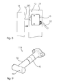
- a switch assembly 12 is formed of a switch unit 10 and a separate actuator 14.
- the switch unit 10 is fixedly mounted to a stationary part 16 of a hoistway, while the actuator 14 is mounted on the door 18 movable with respect to the fixed part 16.
- the actuator 14 moves into a receiving area 20 of the switching unit 10, which in the illustration of Fig. 8 is not visible, but will be explained in more detail below for various embodiments.
- the triggering of an electrical switch in the preferred embodiment by closing a contact, which can be queried by the electrical connection 22 of the switching unit 10 takes place.
- the actuator 14 moves out of the receiving area 20 and the electrical contact within the switching unit 10 is opened again. In this way, by a suitable safety circuit for the elevator system (not shown), the closed state of the door 18 are monitored.
- a seal of the electrical switch is important in addition to a simple and compact design. Meaning this has, for example, that in case of fire, the elevator system should continue to function despite the use of extinguishing water.
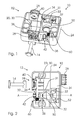
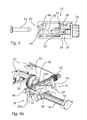
- Fig. 1-3 shows a first embodiment of the switch assembly 12 with the switching unit 10 and the actuator 14.
- the housing 24 encloses the switching unit 10 and has as openings only a sealed with a pinch seal passage 26 for the electrical connection 22 and in the front side wall an inlet opening 28 for the actuator 14. Inside, the housing 24 is divided into mutually separated by side walls 31,33, each closed chambers, namely a receiving chamber 30, a propulsion chamber 32 and a switch chamber 34th
- the receiving area 20 for the actuator 14 is formed within the receiving chamber 30.
- a pivoting element 36 Arranged therein is a pivoting element 36, the shape of which, in particular, can be seen from the illustrations in FIG Fig. 4a .
- Fig. 4b is clearly visible.
- the pivoting element 36 comprises, starting from a shaft 40, a first leg (receiving leg) 36a and a second leg (forked locking leg) 36b.
- the pivoting element 36 is formed integrally with the shaft 40 and can by its rotatable mounting in the housing 24 between a basic position ( Fig. 1-3 . 4a ) and a triggering position ( Fig. 4b ) are pivoted.
- the shaft 40 extends through an opening in an inner partition wall 31 into the propulsion chamber 32.
- a switch actuating element 38 which can be displaced longitudinally in an actuating direction in a guide is arranged, which is coupled to the shaft 40 via a propulsion coupling 42.
- the propulsion coupling is 42 formed by an integrally formed on the shaft 40 Mitauergabel 44 and provided on the switch actuating element 38 cam 46 which is received in the Mitauergabel 44.
- a leg spring 60 is provided in the propulsion chamber 32.
- the leg spring 60 acts on the shaft 40 in such a way that it in the direction of Fig. 1, Fig. 2 .
- Fig. 4a illustrated basic position of the pivot member 36 is reset for receiving the actuator 14.
- the switch actuating element 38 extends, in particular from the sectional view in FIG Fig. 3 can be seen, through an opening 48 in an inner partition wall 33 to the switch chamber 34.
- the opening 48 is sealed to the switch actuator 38 while a seal in the form of a bellows 50.
- Fig. 4a In the switch chamber is, as in particular from the perspective views Fig. 4a .
- Fig. 4b can be seen, an electrical switch element comprising two electrical contacts 52.
- On the switch actuator 38 is also in Fig. 4a .
- Fig. 4b illustrated contact bridge 54 arranged.
- Fig. 4b separately shown in two different switching states mechanism that when a recording of the actuator 14 in the receiving space 20 of the switch closed, so the electrical contact between the contacts 52 is made, while the retraction of the actuator 14 from the receiving space 20 of the switch is opened again.
- the mechanism for coupling the electrical switching function to the position of the actuator 14 includes, as shown, the pivot member 36, the shaft 40, the propulsion coupling 42, the switch actuator 38, and the switch element formed from the contact bridge 54 and the electrical contacts 52.
- the actuator 14 at its longitudinally aligned shaft 56 has a T-shaped, transversely arranged head 58.
- the receiving leg 36a behind the inlet opening 28 is arranged so that the head 58 of the actuator presses against movement in the retraction direction against it, and so Pivoting element 36, and thus also the integrally formed therewith axis 40 and driving fork 44 against the force of the spring 60 is pivoted.
- Fig. 1, Fig. 2 can be seen at the bottom of the receiving chamber 30 rails for guiding provided which are comb-like manner in the embodiment shown with the receiving leg 36a of the pivot member 36 so that retraction of the actuator 14 in the receiving area 20 is only possible if the pivot member 36 is pivoted ,
- the locking leg 36b By the pivoting movement of the locking leg 36b locks the head 58 of the actuator 14 in the receiving area 20.
- the locking leg 36b is fork-shaped, wherein the shaft 56 of the actuator 14 as in Fig. 4b shown in the fork.
- the electrical switching function is triggered by the pivoting movement of the pivoting element 36, in that the switch actuating element 38 is moved further in the longitudinal direction (actuating direction) into the switch chamber 34 via the propulsion coupling 42, as shown in FIG Fig. 4b shown the contact bridge 54 rests against the contacts 52 and so makes the electrical contact.
- the contact bridge 54 is resilient and selected by the Vorreteenkplung 42 predetermined path accordingly, so that due to a certain deflection of the contact bridge 54, a resilient contact with the contacts 52 is given.
- the switching unit 10 as in particular Fig. 2 can be seen, a relatively small space in the retraction of the actuator 14, while still the above-mentioned Kochfahrweg remains ensured.
- the longitudinally displaceable switch actuator 38 can be arranged with its actuating direction parallel to the retraction, but spaced from the receiving space 20.
- the switching unit 10 is constructed so that the electrical switch element from the contacts 52 and the contact bridge 54 is completely sealed.
- the switch chamber 54 is completely closed off except for the sealed cable connection 26 and the opening 48 to the drive chamber 32.
- the opening 48 is sealed by the bellows 50 so that movement of the switch actuating element 38 in the longitudinal direction is possible without hindrance, but at the same time the seal is completely guaranteed.
- the propulsion chamber 32 is already separated from the open receiving chamber 30 by the inner dividing wall 31, which is penetrated only by the shaft 40, so that a multi-stage seal is achieved. Therefore, even when exposed to spray water from the outside, the sufficient sealing of the switch chamber 34 can be ensured.
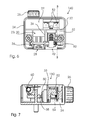
- a second embodiment of a switching unit 110 is shown.
- the switching unit 110 largely corresponds to the switching unit 10 according to the first embodiment described above.
- the same elements are marked with the same reference numerals.
- the propulsion coupling 42 instead of as described above with a driving fork and a cam now executed by means of a gear member 144 formed integrally with the shaft 40 and a gear portion 146 disposed on the switch operating member 38.
- the gear member 144 in the illustrated embodiment is formed only as a partial gear having a gear portion extending only over a part of its circumference. This is possible due to the limited range of movement predetermined by the pivoting movement anyway.
- the gear portion of the gear member 144 is engaged with the linear gear portion 146 of the switch operating member 38 so that even in the second embodiment of a Vortriebskopplung 42, the pivotal movement of the pivot member 36 and the shaft 40 is converted into a linear displacement of the switch actuator member 38 in the longitudinal direction.
- An advantage of the illustrated construction according to both embodiments is the low sensitivity to tolerances in the receiving area 20. As already described, a travel distance for the actuator 14 is ensured. Due to the positive reception of the actuator 14, the function is also ensured even with considerable tolerances in the transverse direction.
- an alternative embodiment of an actuator 114 are used, which has a flexible portion 62 in its shaft 56. While the actuator 14 is otherwise made in one piece, for example, from plastic, in the region 62 at least partially deviating from the rest of the shaft, more flexible material is used, so that the shaft can bend to be received in the receiving space 20.
- the illustrated switching unit can also be used as a door contact for other purposes in which a monitoring of the position of the actuator 14 relative to the switching unit 10, 10 should take place, for example as a machine switch.
Landscapes
- Rotary Switch, Piano Key Switch, And Lever Switch (AREA)
Claims (14)
- Interrupteur avec- une région de réception (20) destinée à recevoir un actionneur (14),- un élément pivotant (36) agencé dans la région de réception (20), lequel est conçu de manière à exécuter un mouvement de pivotement lors d'un mouvement de translation de l'actionneur (14) dans une direction d'insertion dans la région de réception (20),- un élément d'actionnement d'interrupteur (38) apte à coulisser dans une direction d'actionnement pour actionner un élément d'interrupteur électrique (52, 54),- une chambre de traction (32) étant prévue pour la réception d'un accouplement de traction (42), afin de déplacer l'élément d'actionnement d'interrupteur (38) dans la direction d'actionnement,caractérisé en ce que- la chambre de traction (32) est séparée de la région de réception (20) par une paroi (31) traversée par un arbre (40),- et l'accouplement de traction (42) est accouplé à l'élément pivotant (36) par le biais de l'arbre (40), de manière à déplacer l'élément d'actionnement d'interrupteur (38) lors d'un mouvement de pivotement.
- Interrupteur selon la revendication 1, dans lequel- la direction d'actionnement est parallèle à la direction d'insertion,- l'élément d'actionnement d'interrupteur (38) est espacé de la région de réception (20) transversalement à la direction d'actionnement.
- Interrupteur selon l'une des revendications précédentes, dans lequel- la région de réception (20) et l'élément pivotant (36) sont conçus de manière à ce qu'un premier tronçon d'un mouvement de l'actionneur (14) entraîne le mouvement de pivotement,- et à ce que lors d'un mouvement supplémentaire, l'actionneur (14) est reçu dans un espace de dépassement, sans que l'élément pivotant (36) n'effectue un mouvement de pivotement supplémentaire.
- Interrupteur selon l'une des revendications précédentes, dans lequel- il est prévu une chambre d'interrupteur (34) destinée à recevoir l'élément d'interrupteur (52, 54),- la chambre d'interrupteur (34) étant fermée.
- Interrupteur selon la revendication 4, dans lequel- la chambre d'interrupteur (34) est reliée à la chambre de traction (32) par le biais d'un passage (48) pour l'élément d'actionnement d'interrupteur (38), un joint d'étanchéité (50) étant prévu sur le passage.
- Interrupteur selon l'une des revendications précédentes, dans lequel- l'élément pivotant (36) présente une première branche (36a) pour la réception de l'actionneur (14),- de sorte que l'insertion de l'actionneur (14) dans la région de réception (20) entraîne un mouvement de pivotement dans une première direction de pivotement,- et une deuxième branche (36b) pour la réception de l'actionneur (14), de sorte que la sortie de l'actionneur (14) hors de la région de réception (20) entraîne un mouvement de pivotement dans une deuxième direction de pivotement opposée.
- Interrupteur selon l'une des revendications précédentes, dans lequel- l'élément pivotant (36) est conçu avec une tige (56) et une tête (58) pour coopérer avec un actionneur (14),- la première branche (36a) pouvant être déviée par la tête (58) pour amener le mouvement de pivotement,- et la deuxième branche (36b) présente une fourche, l'élément pivotant (36) étant agencé de manière à ce que la tige (56) de l'actionneur (14) soit reçu dans la fourche de façon à ce que la fourche verrouille la tête (58), lors du mouvement de pivotement dans la première direction.
- Interrupteur selon l'une des revendications précédentes, dans lequel- il est prévu un ressort de rappel (60), de sorte que le mouvement de pivotement s'effectue contre la force de ressort.
- Interrupteur selon l'une des revendications précédentes, dans lequel- l'élément d'actionnement d'interrupteur (38) présente une région de denture (146),- et il est prévu un élément de traction (144) accouplé à l'arbre (40), avec une région de pourtour de denture,- la région de denture (146) et la région de pourtour de denture étant en prise l'une avec l'autre, de sorte qu'une rotation de l'élément de traction (144) entraîne un déplacement de l'élément d'actionnement d'interrupteur (38).
- Interrupteur selon l'une des revendications précédentes, dans lequel- l'accouplement de traction (42) présente une fourche d'entraînement (44) accouplée à l'arbre (40),- et l'élément d'actionnement d'interrupteur (38) présente un ergot (46) en prise avec la fourche d'entraînement (44),- de sorte qu'un pivotement de la fourche d'entraînement (44) provoque un déplacement de l'élément d'actionnement d'interrupteur (38).
- Interrupteur selon l'une des revendications précédentes, dans lequel- l'élément d'interrupteur présente deux contacts (52),- et un pont de contact (54) est accouplé à l'élément d'actionnement d'interrupteur (38),- le pont de contact (54) étant agencé à distance d'au moins l'un des deux contacts dans une première position de l'élément d'actionnement d'interrupteur (38), et le pont de contact (54) étant appliqué sur les contacts (52) et reliant ceux-ci électriquement dans une deuxième position de l'élément d'actionnement d'interrupteur (38).
- Bloc d'interrupteur avec- un interrupteur (10, 110) selon l'une des revendications précédentes,- et avec un actionneur (14, 114) agencé de façon à pouvoir se déplacer par rapport à l'interrupteur (10, 110), pour la réception dans la région de réception (20) de l'interrupteur (10, 110).
- Bloc d'interrupteur selon la revendication 12, dans lequel- l'actionneur (114) présente une tige (56) comportant au moins une région souple (62).
- Système de sécurité pour une porte, en particulier pour une porte d'ascenseur, avec- au moins un bloc d'interrupteur (12) selon l'une des revendications 12, 13,- le bloc d'interrupteur (12) étant, en tant que contact de porte, fixé de manière à ce que l'actionneur (14) soit reçu dans la région de réception (20) de l'interrupteur (10, 110) lors de l'ouverture ou de la fermeture de la porte (18).
Applications Claiming Priority (1)
| Application Number | Priority Date | Filing Date | Title |
|---|---|---|---|
| DE102013105373.4A DE102013105373A1 (de) | 2013-05-24 | 2013-05-24 | Schalteinheit zur Aufnahme eines Betätigers |
Publications (2)
| Publication Number | Publication Date |
|---|---|
| EP2806446A1 EP2806446A1 (fr) | 2014-11-26 |
| EP2806446B1 true EP2806446B1 (fr) | 2016-01-06 |
Family
ID=50884674
Family Applications (1)
| Application Number | Title | Priority Date | Filing Date |
|---|---|---|---|
| EP14169489.3A Not-in-force EP2806446B1 (fr) | 2013-05-24 | 2014-05-22 | Interrupteur destiné à la réception d'un actionneur |
Country Status (2)
| Country | Link |
|---|---|
| EP (1) | EP2806446B1 (fr) |
| DE (1) | DE102013105373A1 (fr) |
Family Cites Families (5)
| Publication number | Priority date | Publication date | Assignee | Title |
|---|---|---|---|---|
| DE3943376C1 (fr) * | 1989-12-30 | 1991-06-20 | Kloeckner-Moeller Gmbh, 5300 Bonn, De | |
| DE4303367C1 (de) * | 1993-02-05 | 1994-02-24 | Schmersal K A Gmbh & Co | Sicherheitsschalter |
| DE29504673U1 (de) * | 1995-03-18 | 1996-07-11 | Klöckner-Moeller GmbH, 53115 Bonn | Bewegungsflexibler Betätiger für Sicherheitspositionsschalter |
| JP3620090B2 (ja) * | 1995-04-14 | 2005-02-16 | 富士ゼロックス株式会社 | インターロックスイッチ装置 |
| WO2012113102A1 (fr) * | 2011-02-25 | 2012-08-30 | Honeywell International Inc. | Système et ensemble de commutation électrique |
-
2013
- 2013-05-24 DE DE102013105373.4A patent/DE102013105373A1/de not_active Withdrawn
-
2014
- 2014-05-22 EP EP14169489.3A patent/EP2806446B1/fr not_active Not-in-force
Also Published As
| Publication number | Publication date |
|---|---|
| EP2806446A1 (fr) | 2014-11-26 |
| DE102013105373A1 (de) | 2014-11-27 |
Similar Documents
| Publication | Publication Date | Title |
|---|---|---|
| DE3100862C2 (de) | Sicherheitsschalter | |
| EP3825497B1 (fr) | Serrure de véhicule automobile | |
| EP2174814B1 (fr) | Profilé pour une porte de véhicule dotée d'une protection contre les coincements | |
| EP3336292B1 (fr) | Procédé d'actionnement d'une serrure de porte et serrure de porte | |
| DE102018123949A1 (de) | Betätigungsvorrichtung | |
| EP2584577B1 (fr) | Agencement de sécurisation du commutateur à plusieurs pôles pour systèmes de barre collectrice | |
| EP2476856B1 (fr) | Installation de porte coulissante | |
| EP2957696B1 (fr) | Dispositif de fixation pour un battant | |
| WO2013127377A1 (fr) | Interrupteur protégé contre la poussière et l'eau | |
| EP3002773B1 (fr) | Appareil de commutation équipé d'un dispositif d'arrêt indépendant de l'opérateur | |
| DE69304811T2 (de) | Schloss für die Tür eines Kraftfahrzeuges | |
| EP0330229A2 (fr) | Dispositif de verrouillage | |
| DE20303501U1 (de) | Schloß für eine Tür eines Kraftfahrzeuges | |
| EP3503148B1 (fr) | Unité de contact de commutation destinée à être montée sur un pli entre un châssis dormant et un battant de fenêtre ou de porte | |
| EP2806446A1 (fr) | Interrupteur destiné à la réception d'un actionneur | |
| DE102004037827A1 (de) | Elektrischer Türöffner | |
| DE102004034529B3 (de) | Elektromechanisches Türschloss | |
| DE102012203042B4 (de) | Schaltvorrichtung und Elektrisches Schaltgerät | |
| DE10050138C2 (de) | Antrieb für elektrische Schalter | |
| EP3224110B1 (fr) | Dispositif de contrôle de la position de fin de course de pièces mobiles d'un aiguillage ferroviaire | |
| EP2792827A2 (fr) | Verrouillage de battant de porte ou de fenêtre | |
| DE19922657A1 (de) | Vorrichtung zum Wirksamsetzen einer Öffnungshilfe für verschließbare Teile an Fahrzeugen, wie Klappen, Türen o. dgl. | |
| EP2567389B1 (fr) | Disjoncteur d'installation électrique | |
| EP2618358A1 (fr) | Dispositif de déclenchement pour un disjoncteur | |
| WO2006106078A2 (fr) | Dispositif de detection d'un obstacle situe dans la zone d'ouverture d'un element de fermeture entraine par la force, en particulier d'une vitre de vehicule a moteur |
Legal Events
| Date | Code | Title | Description |
|---|---|---|---|
| PUAI | Public reference made under article 153(3) epc to a published international application that has entered the european phase |
Free format text: ORIGINAL CODE: 0009012 |
|
| 17P | Request for examination filed |
Effective date: 20140522 |
|
| AK | Designated contracting states |
Kind code of ref document: A1 Designated state(s): AL AT BE BG CH CY CZ DE DK EE ES FI FR GB GR HR HU IE IS IT LI LT LU LV MC MK MT NL NO PL PT RO RS SE SI SK SM TR |
|
| AX | Request for extension of the european patent |
Extension state: BA ME |
|
| R17P | Request for examination filed (corrected) |
Effective date: 20150212 |
|
| RBV | Designated contracting states (corrected) |
Designated state(s): AL AT BE BG CH CY CZ DE DK EE ES FI FR GB GR HR HU IE IS IT LI LT LU LV MC MK MT NL NO PL PT RO RS SE SI SK SM TR |
|
| GRAP | Despatch of communication of intention to grant a patent |
Free format text: ORIGINAL CODE: EPIDOSNIGR1 |
|
| RIC1 | Information provided on ipc code assigned before grant |
Ipc: H01H 1/20 20060101ALN20150422BHEP Ipc: H01H 27/00 20060101AFI20150422BHEP Ipc: H01H 9/04 20060101ALN20150422BHEP Ipc: H01H 3/48 20060101ALN20150422BHEP |
|
| INTG | Intention to grant announced |
Effective date: 20150521 |
|
| GRAS | Grant fee paid |
Free format text: ORIGINAL CODE: EPIDOSNIGR3 |
|
| RIC1 | Information provided on ipc code assigned before grant |
Ipc: H01H 27/00 20060101AFI20150930BHEP Ipc: H01H 1/20 20060101ALN20150930BHEP Ipc: H01H 9/04 20060101ALN20150930BHEP Ipc: H01H 3/48 20060101ALN20150930BHEP |
|
| GRAR | Information related to intention to grant a patent recorded |
Free format text: ORIGINAL CODE: EPIDOSNIGR71 |
|
| RIC1 | Information provided on ipc code assigned before grant |
Ipc: H01H 3/48 20060101ALN20151029BHEP Ipc: H01H 27/00 20060101AFI20151029BHEP Ipc: H01H 9/04 20060101ALN20151029BHEP Ipc: H01H 1/20 20060101ALN20151029BHEP |
|
| GRAA | (expected) grant |
Free format text: ORIGINAL CODE: 0009210 |
|
| INTG | Intention to grant announced |
Effective date: 20151111 |
|
| AK | Designated contracting states |
Kind code of ref document: B1 Designated state(s): AL AT BE BG CH CY CZ DE DK EE ES FI FR GB GR HR HU IE IS IT LI LT LU LV MC MK MT NL NO PL PT RO RS SE SI SK SM TR |
|
| REG | Reference to a national code |
Ref country code: GB Ref legal event code: FG4D Free format text: NOT ENGLISH |
|
| REG | Reference to a national code |
Ref country code: CH Ref legal event code: EP |
|
| REG | Reference to a national code |
Ref country code: IE Ref legal event code: FG4D Free format text: LANGUAGE OF EP DOCUMENT: GERMAN |
|
| REG | Reference to a national code |
Ref country code: AT Ref legal event code: REF Ref document number: 769486 Country of ref document: AT Kind code of ref document: T Effective date: 20160215 |
|
| REG | Reference to a national code |
Ref country code: DE Ref legal event code: R096 Ref document number: 502014000268 Country of ref document: DE |
|
| REG | Reference to a national code |
Ref country code: LT Ref legal event code: MG4D |
|
| REG | Reference to a national code |
Ref country code: NL Ref legal event code: MP Effective date: 20160106 |
|
| PG25 | Lapsed in a contracting state [announced via postgrant information from national office to epo] |
Ref country code: NL Free format text: LAPSE BECAUSE OF FAILURE TO SUBMIT A TRANSLATION OF THE DESCRIPTION OR TO PAY THE FEE WITHIN THE PRESCRIBED TIME-LIMIT Effective date: 20160106 |
|
| PG25 | Lapsed in a contracting state [announced via postgrant information from national office to epo] |
Ref country code: FI Free format text: LAPSE BECAUSE OF FAILURE TO SUBMIT A TRANSLATION OF THE DESCRIPTION OR TO PAY THE FEE WITHIN THE PRESCRIBED TIME-LIMIT Effective date: 20160106 Ref country code: HR Free format text: LAPSE BECAUSE OF FAILURE TO SUBMIT A TRANSLATION OF THE DESCRIPTION OR TO PAY THE FEE WITHIN THE PRESCRIBED TIME-LIMIT Effective date: 20160106 Ref country code: GR Free format text: LAPSE BECAUSE OF FAILURE TO SUBMIT A TRANSLATION OF THE DESCRIPTION OR TO PAY THE FEE WITHIN THE PRESCRIBED TIME-LIMIT Effective date: 20160407 Ref country code: ES Free format text: LAPSE BECAUSE OF FAILURE TO SUBMIT A TRANSLATION OF THE DESCRIPTION OR TO PAY THE FEE WITHIN THE PRESCRIBED TIME-LIMIT Effective date: 20160106 Ref country code: NO Free format text: LAPSE BECAUSE OF FAILURE TO SUBMIT A TRANSLATION OF THE DESCRIPTION OR TO PAY THE FEE WITHIN THE PRESCRIBED TIME-LIMIT Effective date: 20160406 |
|
| PG25 | Lapsed in a contracting state [announced via postgrant information from national office to epo] |
Ref country code: RS Free format text: LAPSE BECAUSE OF FAILURE TO SUBMIT A TRANSLATION OF THE DESCRIPTION OR TO PAY THE FEE WITHIN THE PRESCRIBED TIME-LIMIT Effective date: 20160106 Ref country code: BE Free format text: LAPSE BECAUSE OF NON-PAYMENT OF DUE FEES Effective date: 20160531 Ref country code: IS Free format text: LAPSE BECAUSE OF FAILURE TO SUBMIT A TRANSLATION OF THE DESCRIPTION OR TO PAY THE FEE WITHIN THE PRESCRIBED TIME-LIMIT Effective date: 20160506 Ref country code: PL Free format text: LAPSE BECAUSE OF FAILURE TO SUBMIT A TRANSLATION OF THE DESCRIPTION OR TO PAY THE FEE WITHIN THE PRESCRIBED TIME-LIMIT Effective date: 20160106 Ref country code: PT Free format text: LAPSE BECAUSE OF FAILURE TO SUBMIT A TRANSLATION OF THE DESCRIPTION OR TO PAY THE FEE WITHIN THE PRESCRIBED TIME-LIMIT Effective date: 20160506 Ref country code: LT Free format text: LAPSE BECAUSE OF FAILURE TO SUBMIT A TRANSLATION OF THE DESCRIPTION OR TO PAY THE FEE WITHIN THE PRESCRIBED TIME-LIMIT Effective date: 20160106 Ref country code: SE Free format text: LAPSE BECAUSE OF FAILURE TO SUBMIT A TRANSLATION OF THE DESCRIPTION OR TO PAY THE FEE WITHIN THE PRESCRIBED TIME-LIMIT Effective date: 20160106 Ref country code: LV Free format text: LAPSE BECAUSE OF FAILURE TO SUBMIT A TRANSLATION OF THE DESCRIPTION OR TO PAY THE FEE WITHIN THE PRESCRIBED TIME-LIMIT Effective date: 20160106 |
|
| REG | Reference to a national code |
Ref country code: DE Ref legal event code: R097 Ref document number: 502014000268 Country of ref document: DE |
|
| PG25 | Lapsed in a contracting state [announced via postgrant information from national office to epo] |
Ref country code: EE Free format text: LAPSE BECAUSE OF FAILURE TO SUBMIT A TRANSLATION OF THE DESCRIPTION OR TO PAY THE FEE WITHIN THE PRESCRIBED TIME-LIMIT Effective date: 20160106 Ref country code: DK Free format text: LAPSE BECAUSE OF FAILURE TO SUBMIT A TRANSLATION OF THE DESCRIPTION OR TO PAY THE FEE WITHIN THE PRESCRIBED TIME-LIMIT Effective date: 20160106 |
|
| PLBE | No opposition filed within time limit |
Free format text: ORIGINAL CODE: 0009261 |
|
| STAA | Information on the status of an ep patent application or granted ep patent |
Free format text: STATUS: NO OPPOSITION FILED WITHIN TIME LIMIT |
|
| PG25 | Lapsed in a contracting state [announced via postgrant information from national office to epo] |
Ref country code: SM Free format text: LAPSE BECAUSE OF FAILURE TO SUBMIT A TRANSLATION OF THE DESCRIPTION OR TO PAY THE FEE WITHIN THE PRESCRIBED TIME-LIMIT Effective date: 20160106 Ref country code: CZ Free format text: LAPSE BECAUSE OF FAILURE TO SUBMIT A TRANSLATION OF THE DESCRIPTION OR TO PAY THE FEE WITHIN THE PRESCRIBED TIME-LIMIT Effective date: 20160106 Ref country code: SK Free format text: LAPSE BECAUSE OF FAILURE TO SUBMIT A TRANSLATION OF THE DESCRIPTION OR TO PAY THE FEE WITHIN THE PRESCRIBED TIME-LIMIT Effective date: 20160106 Ref country code: RO Free format text: LAPSE BECAUSE OF FAILURE TO SUBMIT A TRANSLATION OF THE DESCRIPTION OR TO PAY THE FEE WITHIN THE PRESCRIBED TIME-LIMIT Effective date: 20160106 |
|
| 26N | No opposition filed |
Effective date: 20161007 |
|
| PG25 | Lapsed in a contracting state [announced via postgrant information from national office to epo] |
Ref country code: LU Free format text: LAPSE BECAUSE OF FAILURE TO SUBMIT A TRANSLATION OF THE DESCRIPTION OR TO PAY THE FEE WITHIN THE PRESCRIBED TIME-LIMIT Effective date: 20160522 |
|
| REG | Reference to a national code |
Ref country code: IE Ref legal event code: MM4A |
|
| PG25 | Lapsed in a contracting state [announced via postgrant information from national office to epo] |
Ref country code: BG Free format text: LAPSE BECAUSE OF FAILURE TO SUBMIT A TRANSLATION OF THE DESCRIPTION OR TO PAY THE FEE WITHIN THE PRESCRIBED TIME-LIMIT Effective date: 20160406 Ref country code: SI Free format text: LAPSE BECAUSE OF FAILURE TO SUBMIT A TRANSLATION OF THE DESCRIPTION OR TO PAY THE FEE WITHIN THE PRESCRIBED TIME-LIMIT Effective date: 20160106 |
|
| REG | Reference to a national code |
Ref country code: FR Ref legal event code: ST Effective date: 20170131 |
|
| PG25 | Lapsed in a contracting state [announced via postgrant information from national office to epo] |
Ref country code: FR Free format text: LAPSE BECAUSE OF NON-PAYMENT OF DUE FEES Effective date: 20160531 |
|
| PG25 | Lapsed in a contracting state [announced via postgrant information from national office to epo] |
Ref country code: IE Free format text: LAPSE BECAUSE OF NON-PAYMENT OF DUE FEES Effective date: 20160522 |
|
| PGFP | Annual fee paid to national office [announced via postgrant information from national office to epo] |
Ref country code: DE Payment date: 20170529 Year of fee payment: 4 |
|
| PGFP | Annual fee paid to national office [announced via postgrant information from national office to epo] |
Ref country code: IT Payment date: 20170531 Year of fee payment: 4 |
|
| REG | Reference to a national code |
Ref country code: CH Ref legal event code: PL |
|
| PG25 | Lapsed in a contracting state [announced via postgrant information from national office to epo] |
Ref country code: CH Free format text: LAPSE BECAUSE OF NON-PAYMENT OF DUE FEES Effective date: 20170531 Ref country code: LI Free format text: LAPSE BECAUSE OF NON-PAYMENT OF DUE FEES Effective date: 20170531 |
|
| PG25 | Lapsed in a contracting state [announced via postgrant information from national office to epo] |
Ref country code: HU Free format text: LAPSE BECAUSE OF FAILURE TO SUBMIT A TRANSLATION OF THE DESCRIPTION OR TO PAY THE FEE WITHIN THE PRESCRIBED TIME-LIMIT; INVALID AB INITIO Effective date: 20140522 |
|
| PG25 | Lapsed in a contracting state [announced via postgrant information from national office to epo] |
Ref country code: MT Free format text: LAPSE BECAUSE OF FAILURE TO SUBMIT A TRANSLATION OF THE DESCRIPTION OR TO PAY THE FEE WITHIN THE PRESCRIBED TIME-LIMIT Effective date: 20160106 Ref country code: CY Free format text: LAPSE BECAUSE OF FAILURE TO SUBMIT A TRANSLATION OF THE DESCRIPTION OR TO PAY THE FEE WITHIN THE PRESCRIBED TIME-LIMIT Effective date: 20160106 Ref country code: MC Free format text: LAPSE BECAUSE OF FAILURE TO SUBMIT A TRANSLATION OF THE DESCRIPTION OR TO PAY THE FEE WITHIN THE PRESCRIBED TIME-LIMIT Effective date: 20160106 Ref country code: MK Free format text: LAPSE BECAUSE OF FAILURE TO SUBMIT A TRANSLATION OF THE DESCRIPTION OR TO PAY THE FEE WITHIN THE PRESCRIBED TIME-LIMIT Effective date: 20160106 |
|
| PG25 | Lapsed in a contracting state [announced via postgrant information from national office to epo] |
Ref country code: AL Free format text: LAPSE BECAUSE OF FAILURE TO SUBMIT A TRANSLATION OF THE DESCRIPTION OR TO PAY THE FEE WITHIN THE PRESCRIBED TIME-LIMIT Effective date: 20160106 Ref country code: TR Free format text: LAPSE BECAUSE OF FAILURE TO SUBMIT A TRANSLATION OF THE DESCRIPTION OR TO PAY THE FEE WITHIN THE PRESCRIBED TIME-LIMIT Effective date: 20160106 |
|
| REG | Reference to a national code |
Ref country code: DE Ref legal event code: R119 Ref document number: 502014000268 Country of ref document: DE |
|
| GBPC | Gb: european patent ceased through non-payment of renewal fee |
Effective date: 20180522 |
|
| PG25 | Lapsed in a contracting state [announced via postgrant information from national office to epo] |
Ref country code: DE Free format text: LAPSE BECAUSE OF NON-PAYMENT OF DUE FEES Effective date: 20181201 Ref country code: IT Free format text: LAPSE BECAUSE OF NON-PAYMENT OF DUE FEES Effective date: 20180522 Ref country code: GB Free format text: LAPSE BECAUSE OF NON-PAYMENT OF DUE FEES Effective date: 20180522 |
|
| REG | Reference to a national code |
Ref country code: AT Ref legal event code: MM01 Ref document number: 769486 Country of ref document: AT Kind code of ref document: T Effective date: 20190522 |
|
| PG25 | Lapsed in a contracting state [announced via postgrant information from national office to epo] |
Ref country code: AT Free format text: LAPSE BECAUSE OF NON-PAYMENT OF DUE FEES Effective date: 20190522 |