EP2806265A1 - Vorrichtung für gefriernachweis - Google Patents
Vorrichtung für gefriernachweis Download PDFInfo
- Publication number
- EP2806265A1 EP2806265A1 EP13738758.5A EP13738758A EP2806265A1 EP 2806265 A1 EP2806265 A1 EP 2806265A1 EP 13738758 A EP13738758 A EP 13738758A EP 2806265 A1 EP2806265 A1 EP 2806265A1
- Authority
- EP
- European Patent Office
- Prior art keywords
- liquid
- detecting unit
- temperature detecting
- ice
- temperature
- Prior art date
- Legal status (The legal status is an assumption and is not a legal conclusion. Google has not performed a legal analysis and makes no representation as to the accuracy of the status listed.)
- Granted
Links
Images

Classifications
-
- F—MECHANICAL ENGINEERING; LIGHTING; HEATING; WEAPONS; BLASTING
- F25—REFRIGERATION OR COOLING; COMBINED HEATING AND REFRIGERATION SYSTEMS; HEAT PUMP SYSTEMS; MANUFACTURE OR STORAGE OF ICE; LIQUEFACTION SOLIDIFICATION OF GASES
- F25D—REFRIGERATORS; COLD ROOMS; ICE-BOXES; COOLING OR FREEZING APPARATUS NOT OTHERWISE PROVIDED FOR
- F25D21/00—Defrosting; Preventing frosting; Removing condensed or defrost water
- F25D21/02—Detecting the presence of frost or condensate
-
- B—PERFORMING OPERATIONS; TRANSPORTING
- B67—OPENING, CLOSING OR CLEANING BOTTLES, JARS OR SIMILAR CONTAINERS; LIQUID HANDLING
- B67D—DISPENSING, DELIVERING OR TRANSFERRING LIQUIDS, NOT OTHERWISE PROVIDED FOR
- B67D1/00—Apparatus or devices for dispensing beverages on draught
- B67D1/08—Details
- B67D1/0857—Cooling arrangements
-
- F—MECHANICAL ENGINEERING; LIGHTING; HEATING; WEAPONS; BLASTING
- F25—REFRIGERATION OR COOLING; COMBINED HEATING AND REFRIGERATION SYSTEMS; HEAT PUMP SYSTEMS; MANUFACTURE OR STORAGE OF ICE; LIQUEFACTION SOLIDIFICATION OF GASES
- F25D—REFRIGERATORS; COLD ROOMS; ICE-BOXES; COOLING OR FREEZING APPARATUS NOT OTHERWISE PROVIDED FOR
- F25D31/00—Other cooling or freezing apparatus
- F25D31/002—Liquid coolers, e.g. beverage cooler
- F25D31/003—Liquid coolers, e.g. beverage cooler with immersed cooling element
-
- G—PHYSICS
- G01—MEASURING; TESTING
- G01K—MEASURING TEMPERATURE; MEASURING QUANTITY OF HEAT; THERMALLY-SENSITIVE ELEMENTS NOT OTHERWISE PROVIDED FOR
- G01K7/00—Measuring temperature based on the use of electric or magnetic elements directly sensitive to heat ; Power supply therefor, e.g. using thermoelectric elements
- G01K7/16—Measuring temperature based on the use of electric or magnetic elements directly sensitive to heat ; Power supply therefor, e.g. using thermoelectric elements using resistive elements
-
- G—PHYSICS
- G01—MEASURING; TESTING
- G01N—INVESTIGATING OR ANALYSING MATERIALS BY DETERMINING THEIR CHEMICAL OR PHYSICAL PROPERTIES
- G01N25/00—Investigating or analyzing materials by the use of thermal means
- G01N25/02—Investigating or analyzing materials by the use of thermal means by investigating changes of state or changes of phase; by investigating sintering
- G01N25/04—Investigating or analyzing materials by the use of thermal means by investigating changes of state or changes of phase; by investigating sintering of melting point; of freezing point; of softening point
- G01N25/06—Analysis by measuring change of freezing point
-
- B—PERFORMING OPERATIONS; TRANSPORTING
- B67—OPENING, CLOSING OR CLEANING BOTTLES, JARS OR SIMILAR CONTAINERS; LIQUID HANDLING
- B67D—DISPENSING, DELIVERING OR TRANSFERRING LIQUIDS, NOT OTHERWISE PROVIDED FOR
- B67D1/00—Apparatus or devices for dispensing beverages on draught
- B67D1/08—Details
- B67D1/0857—Cooling arrangements
- B67D1/0858—Cooling arrangements using compression systems
- B67D1/0859—Cooling arrangements using compression systems the evaporator being in direct heat contact with the beverage, e.g. placed inside a beverage container
-
- B—PERFORMING OPERATIONS; TRANSPORTING
- B67—OPENING, CLOSING OR CLEANING BOTTLES, JARS OR SIMILAR CONTAINERS; LIQUID HANDLING
- B67D—DISPENSING, DELIVERING OR TRANSFERRING LIQUIDS, NOT OTHERWISE PROVIDED FOR
- B67D1/00—Apparatus or devices for dispensing beverages on draught
- B67D1/08—Details
- B67D1/0878—Safety, warning or controlling devices
-
- B—PERFORMING OPERATIONS; TRANSPORTING
- B67—OPENING, CLOSING OR CLEANING BOTTLES, JARS OR SIMILAR CONTAINERS; LIQUID HANDLING
- B67D—DISPENSING, DELIVERING OR TRANSFERRING LIQUIDS, NOT OTHERWISE PROVIDED FOR
- B67D2210/00—Indexing scheme relating to aspects and details of apparatus or devices for dispensing beverages on draught or for controlling flow of liquids under gravity from storage containers for dispensing purposes
- B67D2210/00028—Constructional details
- B67D2210/00099—Temperature control
- B67D2210/00104—Cooling only
-
- F—MECHANICAL ENGINEERING; LIGHTING; HEATING; WEAPONS; BLASTING
- F25—REFRIGERATION OR COOLING; COMBINED HEATING AND REFRIGERATION SYSTEMS; HEAT PUMP SYSTEMS; MANUFACTURE OR STORAGE OF ICE; LIQUEFACTION SOLIDIFICATION OF GASES
- F25B—REFRIGERATION MACHINES, PLANTS OR SYSTEMS; COMBINED HEATING AND REFRIGERATION SYSTEMS; HEAT PUMP SYSTEMS
- F25B2700/00—Sensing or detecting of parameters; Sensors therefor
- F25B2700/11—Sensor to detect if defrost is necessary
-
- F—MECHANICAL ENGINEERING; LIGHTING; HEATING; WEAPONS; BLASTING
- F25—REFRIGERATION OR COOLING; COMBINED HEATING AND REFRIGERATION SYSTEMS; HEAT PUMP SYSTEMS; MANUFACTURE OR STORAGE OF ICE; LIQUEFACTION SOLIDIFICATION OF GASES
- F25D—REFRIGERATORS; COLD ROOMS; ICE-BOXES; COOLING OR FREEZING APPARATUS NOT OTHERWISE PROVIDED FOR
- F25D2700/00—Means for sensing or measuring; Sensors therefor
- F25D2700/12—Sensors measuring the inside temperature
-
- G—PHYSICS
- G01—MEASURING; TESTING
- G01N—INVESTIGATING OR ANALYSING MATERIALS BY DETERMINING THEIR CHEMICAL OR PHYSICAL PROPERTIES
- G01N33/00—Investigating or analysing materials by specific methods not covered by groups G01N1/00 - G01N31/00
- G01N33/02—Food
- G01N33/14—Beverages
- G01N33/146—Beverages containing alcohol
Definitions
- the present invention relates to a freezing detection device to be applied to e.g. a beverage cooling apparatus for making beverages (e.g. beer) cold.
- beverages e.g. beer
- the ice thermal-storage cooling apparatus cools water (beverage cooling liquid) stored in a water tank provided inside the cooling apparatus by an evaporator of a vapor-compression refrigerator located in the water tank so that ice is formed around the evaporator for thermal storage, and cools beer by allowing the beer guided from a beer keg to pass through a pipe placed inside the water tank so that the beer is cooled to an appropriate temperature for drinking (e.g. about 5 °C).
- water beverage cooling liquid
- such an ice thermal-storage cooling apparatus is provided with a freezing detection device for detecting that the amount of ice formed around the evaporator has reached the predetermined amount.
- a conventional freezing detection device is provided with a pair of electrodes at a position corresponding to a desired amount of ice, and determines whether or not the water has frozen around the electrodes on the basis of a difference in electrical conductivity between water in a liquid state and water having frozen into a solid state, thereby determining whether or not the desired amount of ice has been formed.
- Such a conventional freezing detection device sometimes makes an incorrect determination that the desired amount of ice has been formed in spite of the fact that the desired amount of ice has not been formed, due to decrease in electrical conductivity of the water stored in the water tank, when the water stored in the water tank has changed in quality with the passage of time, and the amount of electrolyte contained in the water has decreased.
- beverage having an appropriate temperature for drinking (e.g. -2 °C) that is lower than the temperature to which a conventional ice thermal-storage cooling apparatus can cool the beverage.
- an apparatus for cooling such beverages to the appropriate temperature for drinking there is known an apparatus which utilizes an antifreeze liquid whose freezing temperature is lower than that of water, instead of water, as a beverage cooling liquid and cools the antifreeze liquid by a vapor-compression refrigerator to achieve the temperature of beverage which is lower than that achieved by a conventional ice thermal-storage cooling apparatus.
- an antifreeze liquid as a beverage cooling liquid in such a manner, it is difficult to determine on the basis of a difference in electrical conductivity whether or not the antifreeze liquid has frozen because the antifreeze liquid, which is usually higher in electrical conductivity than water, exhibits a high electrical conductivity even in a frozen state.
- Japanese Patent Application Laid-Open No. 2011-73775 describes a beer server including a freezing sensor located in the vicinity of an evaporator pipe in a water tank and configured to detect on the basis of change in electrical resistance (electrical conductivity) of water whether or not a predetermined thickness of ice has been formed around the evaporator pipe; and a beer server including a temperature sensor for freezing detection configured to detect whether or not a predetermined thickness of ice has been formed around an evaporator pipe through the use of a difference in temperature between cooling water and ice.
- a freezing sensor located in the vicinity of an evaporator pipe in a water tank and configured to detect on the basis of change in electrical resistance (electrical conductivity) of water whether or not a predetermined thickness of ice has been formed around the evaporator pipe
- a beer server including a temperature sensor for freezing detection configured to detect whether or not a predetermined thickness of ice has been formed around an evaporator pipe through the use of a difference in temperature between cooling water and ice.
- Patent Document 1 Japanese Patent Application Laid-Open No. 2011-73775 ( ⁇ 0047, 0048, FIG. 2 , ⁇ 0080, FIG. 12)
- An object of the present invention is to provide a freezing detection device capable of determining whether a liquid whose freezing is to be detected has frozen or not, irrespective of electrical conductivity of the liquid whose freezing is to be detected.
- a freezing detection device is a freezing detection device to be applied to a liquid cooling apparatus including a liquid tank for storing a liquid whose freezing is to be detected and a cooling unit located inside the liquid tank to cool the liquid, and the freezing detection device comprises: a temperature detecting unit located at a predetermined distance from the cooling unit; and a determining unit configured to determine whether or not the liquid has frozen around the temperature detecting unit based on an output from the temperature detecting unit, the determining unit determining whether or not the liquid has frozen around the temperature detecting unit based on whether the output from the temperature detecting unit is fluctuating or not.
- the determining unit may be configured to determine that the liquid has not frozen around the temperature detecting unit when the output from the temperature detecting unit is fluctuating, and determine that the liquid has frozen around the temperature detecting unit when the output from the temperature detecting unit is not fluctuating. Furthermore, the determining unit may be configured to determine whether or not the liquid has frozen around the temperature detecting unit based on whether a temperature detected by the temperature detecting unit is fluctuating or not.
- the temperature detecting unit may comprise a thermistor (e.g. NTC thermistor).
- a thermistor e.g. NTC thermistor
- a liquid cooling apparatus comprises: a liquid tank for storing a liquid whose freezing is to be detected; a cooling unit located inside the liquid tank to cool the liquid; and the above-described freezing detection device.
- the liquid cooling apparatus may further comprise an agitator configured to stir the liquid stored in the liquid tank.
- the cooling unit may comprise an evaporator of a vapor-compression refrigerator.
- the vapor-compression refrigerator may be controlled to operate when the determining unit determines that the liquid has not frozen around the temperature detecting unit, and to stop operating when the determining unit determines that the liquid has frozen around the temperature detecting unit.
- the liquid may be e.g. water or an antifreeze liquid.
- a beverage cooling apparatus comprises: the above-described liquid cooling apparatus; and a beverage-channel-defining section defining a beverage channel through which a beverage to be cooled is allowed to flow, the beverage-channel-defining section being located inside the liquid tank.
- the freezing detection device may determine whether or not a desired amount of ice has been formed around the cooling unit. Furthermore, the temperature detecting unit may be located at a position corresponding to the desired amount.
- the present invention it is possible to determine whether a liquid whose freezing is to be detected has frozen or not, irrespective of electrical conductivity of the liquid whose freezing is to be detected.
- beer cooling apparatus for cooling beer as a beverage
- This beer cooling apparatus is used for cooling beer supplied from an outside source. More specifically, this beer cooling apparatus is configured to cool beer at a predetermined temperature (e.g. 25 °C) supplied from an outside source (e.g. a beer keg) to a predetermined appropriate temperature for drinking (e.g. about 5 °C), and supply the cooled beer to an outside destination (e.g. a pouring tap).
- a predetermined temperature e.g. 25 °C
- an outside source e.g. a beer keg
- predetermined appropriate temperature for drinking e.g. about 5 °C
- FIG. 1 is an explanatory view of a structure of a beer cooling apparatus incorporating a freezing detection device according to the present invention.
- the beer cooling apparatus 100 to which a freezing detection device according to the present invention is applied, includes a liquid tank 110, an ice-making pipe 120, a beverage cooling pipe 130, a cooling liquid agitator 140, a temperature detecting unit 150 and a control unit 160.
- the liquid tank 110 is a container for storing a cooling liquid (water in the case of the present embodiment) 111 for cooling beer as a beverage to be cooled.
- cooling liquid 111 is the subject of freezing detection by the freezing detection device according to the present invention.
- the ice-making pipe 120 (cooling unit), located inside the liquid tank 110 to cool the cooling liquid 111 stored in the liquid tank 110, is in a shape of a pipe formed in a coiled (spiral) manner and allows a refrigerant (e.g. chlorofluorocarbon) to pass therethrough.
- a refrigerant e.g. chlorofluorocarbon
- FIG. 1 and the like show only a cross-section of the ice-making pipe 120.
- the ice-making pipe 120 comprises an evaporator of a vapor-compression refrigerator.
- the ice-making pipe 120 is connected to a compressor 101, a condenser 102, and the like to constitute a refrigeration cycle.
- the refrigerant discharged though the other end of the ice-making pipe 120 (an end 122 located on the lower side in the case of this embodiment) is returned to the compressor 101.
- the beverage cooling pipe 130 (beverage-channel-defining section), located inside the liquid tank 110, defines a beverage channel through which a beverage (beer in the case of this embodiment) is allowed to pass, inside the liquid tank 110.
- a beverage beer in the case of this embodiment
- the beverage cooling pipe 130 is in a shape of a pipe formed in a coiled (spiral) manner and allows beer to pass therethrough. It is to be noted that, for the sake of simplicity, FIG. 1 and the like show only a cross-section of the beverage cooling pipe 130, as in the case of the ice-making pipe 120.
- the beverage cooling pipe 130 is formed such that a coil thereof is smaller in diameter than a coil of the ice-making pipe 120, and the coil formed by the beverage cooling pipe 130 is placed inside the coil formed by the ice-making pipe 120.
- Beer introduced from an outside source e.g. a beer keg
- a predetermined temperature e.g. 5 °C
- the cooling liquid 111 stored in the liquid tank 110 is cooled to a predetermined temperature (e.g. 5 °C) by the cooling liquid 111 stored in the liquid tank 110 during passage through the beverage cooling pipe 130, and the beer thus cooled is delivered to an outside destination (e.g. a pouring tap) through the other end of the beverage cooling pipe 130 (an end 132 located on the upper side in the case of this embodiment).
- the cooling liquid agitator 140 configured to stir the cooling liquid 111 stored in the liquid tank 110 so that the cooling liquid 111 is uniformly cooled, includes a stirring fin 141 and a stirring motor 142.
- the stirring fin 141 is located inside the liquid tank 110 to stir the cooling liquid 111 stored in the liquid tank 110.
- the stirring motor 142 is connected to the stirring fin 140 to drive the stirring fin 141 to rotate.
- the stirring fin 141 is located inside a hollow cylinder defined by the beverage cooling pipe 130, and rotation of the stirring fin 141 causes the cooling liquid to flow downward in the hollow cylinder defined by the beverage cooling pipe 130. When the cooling liquid flowing downward collides with a bottom surface of the liquid tank 110, then the cooling liquid is caused by the collision to flow outward.
- the temperature detecting unit 150 comprises the freezing detection device according to the present invention, and is placed in the vicinity of the ice-making pipe 120.
- the temperature detecting unit 150 includes a detecting unit 151 and a mounting section 152.
- the detecting unit 151 has its tip (temperature detecting portion) located in the vicinity of the ice-making pipe 120 to detect the temperature of an area around the tip.
- the detecting unit 151 is obtained by placing a thermistor (NTC thermistor in the case of this embodiment) in an inside (tip portion) of a cylindrical stainless-steel case.
- the mounting section 152 fixes the detecting unit 151 such that the tip of the detecting unit 151 is located at a predetermined position.
- the temperature detecting unit 150 is mounted on the liquid tank 110 such that the tip of the detecting unit 151 is located at a position corresponding to a desired amount of ice.
- the control unit 160 controls the operation of the beer cooling apparatus 100.
- the functions of the control unit 160 are basically implemented by a microprocessor.
- the control unit 160 along with the temperature detecting unit 150, comprises the freezing detection device according to the present invention.
- the control unit 160 comprises a determining unit configured to determine whether or not a liquid whose freezing is to be detected (the cooling liquid 111 in the case of this embodiment) has frozen around the temperature detecting unit 150 based on an output from the temperature detecting unit 150.
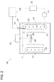
- FIG. 2 is a view showing a state where ice has been formed around the ice-making pipe 120.
- FIG. 2 shows a state where the desired amount of ice has been formed.
- the temperature detecting unit 150 is located at such a position that its tip (temperature detecting portion) is buried in the ice 123 at a point in time when the desired amount of ice 123 has been formed around the ice-making pipe 120.
- the control unit 160 starts the operation of the compressor 101.
- a refrigerant introduced into the ice-making pipe 120 through the condenser 102 and an expansion valve (not shown) evaporates to cool the cooling liquid 111 stored in the liquid tank 110.
- ice is caused to start being formed around the ice-making pipe 120 after a while.
- the compressor 101 so as to continuously cool the cooling liquid 111 stored in the liquid tank 110, the ice formed around the ice-making pipe 120 is caused to grow and eventually reach the tip of the temperature detecting unit 150, with the result that, as shown in FIG. 2 , the tip of the temperature detecting unit 150 comes to be buried in the ice 123.
- the control unit 160 which comprises the freezing detection device along with the temperature detecting unit 150, starts monitoring whether or not the tip of the temperature detecting unit 150 has been buried in ice based on an output signal from the temperature detecting unit 150. Then, upon detection of the fact that the tip of the temperature detecting unit 150 has been buried in ice, i.e., the state where a predetermined amount of ice has been formed, the control unit 160 stops the operation of the compressor 101.
- a predetermined temperature e.g. a freezing temperature
- the control unit 160 which comprises the freezing detection device along with the temperature detecting unit 150, starts monitoring whether or not the tip of the temperature detecting unit 150 has been buried in ice based on an output signal from the temperature detecting unit 150. Then, upon detection of the fact that the tip of the temperature detecting unit 150 has been buried in ice, i.e., the state where a predetermined amount of ice has been formed, the control unit 160 stops the operation of the compressor 101.
- the control unit 160 appropriately monitors whether the ice formed around the ice-making pipe 120 has melted to the extent that the tip of the temperature detecting unit 150 is exposed out of the ice. Then, upon detection of the fact that the tip of the temperature detecting unit 150 is exposed out of the ice, i.e., the state where the amount of ice formed around the ice-making pipe 120 is less than the predetermined amount, the control unit 160 starts the operation of the compressor 101 again. In such a manner, after the predetermined amount of ice has been formed around the ice-making pipe 120, the control unit 160 performs the on-off control of the compressor 101 such that the predetermined amount of ice is maintained.
- beer introduced into the beverage cooling pipe 130 through the one end 131 thereof is cooled to a desired temperature (e.g. 5 °C) by the cooling liquid 111 stored in the liquid tank 110 during passage through the beverage cooling pipe 130 to be delivered from the other end 132 thereof.
- a desired temperature e.g. 5 °C
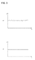
- FIG. 3 is time-dependent temperature graphs each showing how the temperature detected by a temperature detecting unit 150 varies as a function of time.
- the horizontal axis represents time (t)
- the vertical axis represents temperature (T).
- FIG. 3 (a) shows time variation of temperature when ice has been formed around the ice-making pipe 120 but has not reached an area around the tip of the temperature detecting unit 150.
- FIG. 3 (b) shows time variation of temperature when the ice formed around the ice-making pipe 120 has grown to reach an area around the tip of the temperature detecting unit 150 as shown in FIG. 2 .
- the tip (a portion at which the NTC thermistor is located) of the temperature detecting unit 150 is exposed to the cooling liquid 111.
- the cooling liquid 111 stored in the liquid tank 110 is stirred by the cooling liquid agitator 140, there is a flow of the cooling liquid 111 inside the liquid tank 110.
- the tip of the temperature detecting unit 150 is always subjected to collision with the flow of the cooling liquid 111.
- the cooling liquid 111 stored in the liquid tank 110 is cooled gradually from an area around the ice-making pipe 120, there occurs a certain degree of temperature difference depending upon regions inside the liquid tank 110.
- the stirring of the cooling liquid 111 by the cooling liquid agitator 140 gives rise to a certain degree of temperature difference for the cooling liquid colliding with the tip of the temperature detecting unit 150.
- the temperature detected by the temperature detecting unit 150 fluctuates within a certain range with the passage of time.
- the freezing detection device discriminates such a difference in temporal variation of the temperature detected by the temperature detecting unit 150, thereby determining whether or not the tip of the temperature detecting unit 150 has been buried in ice, i.e., whether or not the cooling liquid has frozen around the tip of the temperature detecting unit 150.
- the freezing detection device determines that the tip of the temperature detecting unit 150 is not buried in ice, i.e., no ice is formed in the proximity of the tip of the temperature detecting unit 150.
- the freezing detection device determines that the tip of the temperature detecting unit 150 is buried in ice, i.e., ice has been formed around the tip of the temperature detecting unit 150.
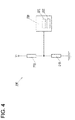
- FIG. 4 is a diagram showing an example configuration of a temperature detecting circuit used for realizing the freezing detection device according to the present invention.
- the temperature detecting circuit 200 includes an NTC thermistor 210, a resistor 220, and a microprocessor 230.
- the NTC thermistor 210 comprises the temperature detecting unit 150
- the microprocessor 230 comprises the control unit 160.
- the NTC thermistor 210 has one terminal grounded, and has the other terminal connected to one terminal of the resistor 220 as well as an analog input terminal of the microprocessor 230.
- the resistor 220 has the other terminal connected to a power supply voltage V+.
- a variation of resistance value of the NTC thermistor 210 occurring in accordance with a variation of ambient temperature leads to a variation of voltage value of a signal input to the microprocessor 230.
- the microprocessor 230 has an A/D converter 231 incorporated therein, and the voltage value (analog data) of a signal input through the analog input terminal is converted appropriately by the A/D converter 231 into digital data.
- the microprocessor 230 operates the A/D converter 231 at regular intervals (e.g. every 0.1 second) so as to convert the voltage value of a signal input through the analog input terminal into digital data, and further converts the digitized voltage value into a temperature (temperature data) in accordance with a conversion table prepared in advance (sampling).
- a plurality of pieces of temperature data thus obtained are stored in sequence by the microprocessor 230 in a temperature data storage area allocated in an internal memory 232 of the microprocessor 230 (or in an external memory which is not shown).
- the temperature data storage area such a size is reserved that a predetermined amount of temperature data (e.g. 100 pieces of temperature data) over a predetermined period of time (e.g. 10 seconds) can be stored. Furthermore, the temperature data storage area is managed in such a manner that the temperature data storage area forms a ring buffer, and that, after a predetermined period of time (e.g. 10 seconds) has elapsed, a predetermined amount (e.g. 100 pieces) of the most recent temperature data over a predetermined period of time (e.g. 10 seconds) is always stored in the temperature data storage area.
- a predetermined amount of temperature data e.g. 100 pieces of temperature data
- a predetermined period of time e.g. 10 seconds
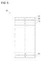
- FIG. 5 is an explanatory diagram of a structure of a temperature data storage area.
- the temperature data storage area 500 is a data storage area having such a size that a predetermined amount of temperature data T 1 to T N (N pieces of temperature data in the example shown in FIG. 5 ) can be stored.
- the microprocessor 230 stores the temperature data T 1 in an area 501 located at the top of the temperature data storage area 500. Subsequently, upon obtaining temperature data T 2 at a time t 2 through sampling at the time t 2 as a sampling time subsequent to the time t 1 , the microprocessor 230 stores the temperature data T 2 in an area 502 located subsequently to the area 501.
- the microprocessor 230 stores the temperature data T 3 in an area 503 located subsequently to the area 502.
- the microprocessor 230 repeats such a process at each sampling time.
- the microprocessor 230 stores the temperature data T N in an area 511 located at the bottom of the temperature data storage area 500.
- N pieces of temperature data T 1 to T N over the predetermined period of time i.e., the time t 1 to time t N are stored in the temperature data storage area 500.
- the microprocessor 230 upon obtaining temperature data T N+1 at a time t N+1 through sampling at the time t N+1 as a sampling time subsequent to the time t N , the microprocessor 230 returns to the area 501 located at the top to store the temperature data T N+1 in the area 501.
- N pieces of the most recent temperature data T 2 to T N+1 over the time t 2 to time t N+1 are stored in the temperature data storage area 500.
- the area 502 is the first area and the area 501 is the last area while the areas 503, 511, and the like are therebetween.
- the microprocessor 230 stores the temperature data T N+2 in the area 502 located subsequently to the area 501.
- N pieces of the most recent temperature data T 3 to T N+2 over the time t 3 to time t N+2 are stored in the temperature data storage area 500.
- the area 503 is the first area and the area 502 is the last area while the areas 511, 501, and the like are therebetween.
- N pieces of the most recent temperature data over a predetermined period of time are always stored in the temperature data storage area 500.
- the addresses of the logically (chronologically) first and last areas are managed appropriately by the microprocessor 230.
- Ti denotes each piece of temperature data stored in the temperature data storage area 500, where T 1 denotes the oldest piece of temperature data stored in the temperature data storage area 500, and T N denotes the most recent piece of temperature data stored in the temperature data storage area 500.
- the microprocessor 230 determines whether or not the sum S thus calculated is greater than or equal to a predetermined threshold value. If the sum S is greater than or equal to the predetermined threshold value, the microprocessor 230 determines that the temperature is varying with the passage of time (i.e. the NTC thermistor 210 is not buried in ice). On the other hand, if the sum S is less than the predetermined threshold value, the microprocessor 230 determines that the temperature is not varying (over a predetermined period of time) (i.e. the NTC thermistor 210 is buried in ice).
- the determination as to whether or not the temperature data stored in the temperature data storage area 500 is varying with the passage of time is made at an appropriate timing in accordance with implementation conditions such as the cycle of fluctuation in temperature, the sampling cycle, and the processing speed of the microprocessor 230.
- the determination is made every time a sampling time comes, and the latest temperature data is stored in the temperature data storage area 500, i.e., every time one of a predetermined number of pieces of temperature data (e.g. 100 pieces of temperature data) over a predetermined period of time (e.g. 10 seconds) stored in the temperature data storage area 500 is updated.
- the freezing detection device it is determined whether or not the tip of the temperature detecting unit 150 has been buried in ice, i.e., whether or not a desired amount of ice has been formed, on the basis of whether or not the temperature detected by the temperature detecting unit 150 is fluctuating (within a predetermined period of time), which enables the freezing detection device to detect the formation of the desired amount of ice irrespective of the electrical conductivity of the cooling liquid 111. For example, therefore, even if the electrical conductivity of the cooling liquid stored in the liquid tank changes with the passage of time, it is possible to determine correctly whether or not the desired amount of ice has been formed. Further, even when an antifreeze liquid exhibiting a high electrical conductivity even in a frozen state is used as the cooling liquid, it is possible to determine whether or not the desired amount of ice has been formed.
- the temperature detecting unit is constituted by an NTC thermistor in the embodiment described above, the temperature detecting unit may alternatively be constituted by other temperature detection means (e.g. a platinum resistance temperature sensor or a thermocouple).
- a digitized voltage value is further converted into temperature data in the embodiment described above, the digitized voltage value may be directly used to determine whether or not the tip of the temperature detecting unit 150 has been buried in ice on the basis of whether the voltage value is fluctuating or not.
- the temperature detecting unit 150 has its tip (temperature detecting portion) located in the vicinity of the end 121 which is on the upper side of the ice-making pipe 120 in the embodiment described above, the temperature detecting unit 150 may alternatively have its tip located at any other position corresponding to a desired amount of ice e.g. in the vicinity of the end 122 which is on the lower side of the ice-making pipe 120.
- water is used as the cooling liquid to be stored in the liquid tank 110 in the embodiment described above, other liquid (e.g. an antifreeze liquid) may alternatively be used.
- other liquid e.g. an antifreeze liquid
Landscapes
- Engineering & Computer Science (AREA)
- Physics & Mathematics (AREA)
- Chemical & Material Sciences (AREA)
- Combustion & Propulsion (AREA)
- Mechanical Engineering (AREA)
- Thermal Sciences (AREA)
- General Engineering & Computer Science (AREA)
- General Physics & Mathematics (AREA)
- Life Sciences & Earth Sciences (AREA)
- Analytical Chemistry (AREA)
- Biochemistry (AREA)
- General Health & Medical Sciences (AREA)
- Health & Medical Sciences (AREA)
- Immunology (AREA)
- Pathology (AREA)
- Devices That Are Associated With Refrigeration Equipment (AREA)
- Investigating Or Analyzing Materials Using Thermal Means (AREA)
- Devices For Dispensing Beverages (AREA)
Applications Claiming Priority (2)
| Application Number | Priority Date | Filing Date | Title |
|---|---|---|---|
| JP2012007506A JP5945378B2 (ja) | 2012-01-17 | 2012-01-17 | 凍結検出装置 |
| PCT/JP2013/050276 WO2013108702A1 (ja) | 2012-01-17 | 2013-01-10 | 凍結検出装置 |
Publications (3)
| Publication Number | Publication Date |
|---|---|
| EP2806265A1 true EP2806265A1 (de) | 2014-11-26 |
| EP2806265A4 EP2806265A4 (de) | 2015-12-23 |
| EP2806265B1 EP2806265B1 (de) | 2021-11-17 |
Family
ID=48799128
Family Applications (1)
| Application Number | Title | Priority Date | Filing Date |
|---|---|---|---|
| EP13738758.5A Not-in-force EP2806265B1 (de) | 2012-01-17 | 2013-01-10 | Vorrichtung für gefriernachweis |
Country Status (4)
| Country | Link |
|---|---|
| US (1) | US9897367B2 (de) |
| EP (1) | EP2806265B1 (de) |
| JP (1) | JP5945378B2 (de) |
| WO (1) | WO2013108702A1 (de) |
Cited By (1)
| Publication number | Priority date | Publication date | Assignee | Title |
|---|---|---|---|---|
| CN108593702A (zh) * | 2017-03-15 | 2018-09-28 | 中山大学 | 适用观察低温固液相变的可视化测试装置及其使用方法 |
Families Citing this family (6)
| Publication number | Priority date | Publication date | Assignee | Title |
|---|---|---|---|---|
| CN105180551B (zh) * | 2014-05-30 | 2017-11-28 | 青岛海尔特种电冰柜有限公司 | 一种罐/瓶体饮品的冷藏方法 |
| CN105202861B (zh) * | 2014-05-30 | 2017-11-28 | 青岛海尔特种电冰柜有限公司 | 一种罐/瓶体饮品速冷机的速冷方法 |
| AU2016351373A1 (en) * | 2015-11-13 | 2018-06-28 | IceColdNow, Inc. | Coldwave appliance |
| SG11202107159UA (en) * | 2019-02-12 | 2021-08-30 | Carlsberg Breweries As | Monitoring of a beverage dispensing system |
| US11479455B2 (en) * | 2019-05-17 | 2022-10-25 | Pepsico, Inc. | Water dispensing station |
| CN112649584A (zh) * | 2020-12-18 | 2021-04-13 | 联想(北京)有限公司 | 一种液体的状态检测方法及设备 |
Family Cites Families (20)
| Publication number | Priority date | Publication date | Assignee | Title |
|---|---|---|---|---|
| US2494512A (en) * | 1946-06-11 | 1950-01-10 | Revco Inc | Milk cooler having automatic control means |
| US3882693A (en) * | 1974-02-01 | 1975-05-13 | Rayne International | Water cooler |
| JPS5559302A (en) * | 1978-10-30 | 1980-05-02 | Mayekawa Mfg Co Ltd | Freezing thickness detector |
| JPS5658650A (en) * | 1979-10-19 | 1981-05-21 | Tsuruga Denki Seisakusho:Kk | Detecting device for freezing |
| JPS596888B2 (ja) * | 1980-09-26 | 1984-02-15 | 川崎製鉄株式会社 | 高炉炉壁の付着物検出方法 |
| US4662184A (en) * | 1986-01-06 | 1987-05-05 | General Electric Company | Single-sensor head pump defrost control system |
| US5022233A (en) * | 1987-11-02 | 1991-06-11 | The Coca-Cola Company | Ice bank control system for beverage dispenser |
| US4907417A (en) * | 1988-03-21 | 1990-03-13 | Emerson Electric Co. | Refrigeration control system for cold drink dispenser |
| US4932222A (en) * | 1988-10-18 | 1990-06-12 | Adams Jr Thomas A | In-line milk cooler |
| JPH0989546A (ja) * | 1995-09-28 | 1997-04-04 | Mitsubishi Materials Corp | 氷厚測定装置 |
| US5839291A (en) * | 1996-08-14 | 1998-11-24 | Multiplex Company, Inc. | Beverage cooling and dispensing system with diagnostics |
| JP3852630B2 (ja) * | 1997-03-11 | 2006-12-06 | オリオン機械株式会社 | 蓄氷式冷水製造装置 |
| US5987897A (en) * | 1997-05-30 | 1999-11-23 | Ranco Incorporated Of Delaware | Ice bank system |
| JP3870308B2 (ja) * | 1997-07-30 | 2007-01-17 | 株式会社大泉製作所 | 製氷検知器 |
| US6581391B2 (en) * | 2000-05-01 | 2003-06-24 | Technology Licensing Corporation | Ice thickness control system and sensor probe |
| JP4269616B2 (ja) * | 2002-09-24 | 2009-05-27 | 株式会社Ihi | 過冷却水製造装置の制御方法及び装置 |
| CA2448893A1 (en) * | 2003-11-12 | 2005-05-12 | Icefloe Technologies Inc. | Method and apparatus for controlled ice crystal formation in a beverage |
| KR100982701B1 (ko) * | 2007-04-24 | 2010-09-17 | 웅진코웨이주식회사 | 수처리 장치 |
| JP5474518B2 (ja) * | 2009-12-14 | 2014-04-16 | アサヒビール株式会社 | 液体供給装置及び冷却水状態判断装置 |
| JP5474481B2 (ja) | 2009-10-01 | 2014-04-16 | アサヒビール株式会社 | 液体供給装置及び稼働状況管理装置 |
-
2012
- 2012-01-17 JP JP2012007506A patent/JP5945378B2/ja active Active
-
2013
- 2013-01-10 EP EP13738758.5A patent/EP2806265B1/de not_active Not-in-force
- 2013-01-10 WO PCT/JP2013/050276 patent/WO2013108702A1/ja not_active Ceased
-
2014
- 2014-07-16 US US14/333,389 patent/US9897367B2/en not_active Expired - Fee Related
Cited By (1)
| Publication number | Priority date | Publication date | Assignee | Title |
|---|---|---|---|---|
| CN108593702A (zh) * | 2017-03-15 | 2018-09-28 | 中山大学 | 适用观察低温固液相变的可视化测试装置及其使用方法 |
Also Published As
| Publication number | Publication date |
|---|---|
| US9897367B2 (en) | 2018-02-20 |
| JP5945378B2 (ja) | 2016-07-05 |
| US20140326009A1 (en) | 2014-11-06 |
| WO2013108702A1 (ja) | 2013-07-25 |
| EP2806265B1 (de) | 2021-11-17 |
| EP2806265A4 (de) | 2015-12-23 |
| JP2013148399A (ja) | 2013-08-01 |
Similar Documents
| Publication | Publication Date | Title |
|---|---|---|
| US9897367B2 (en) | Freezing detection device | |
| US20250172327A1 (en) | Draining the sump of an ice maker to prevent growth of harmful biological material | |
| US10788250B2 (en) | Ice making assemblies and methods for making clear ice | |
| EP2409095B1 (de) | Mikroprozessorgesteuerte abtaubeendigung | |
| US6581391B2 (en) | Ice thickness control system and sensor probe | |
| EP3610209B1 (de) | Ein kühlbad für eine zu kühlende flüssigkeit | |
| US20030000233A1 (en) | Methods and system for cooling device control | |
| CN107796173A (zh) | 用于冷却液体的方法和制冷器具 | |
| KR20140041009A (ko) | 음용수 냉각장치의 온도조절시스템 | |
| JP6689079B2 (ja) | 飲料サーバ | |
| CN217504052U (zh) | 一种提升冰淇淋机制冷性能的制冷系统及冰淇淋机 | |
| JP5875797B2 (ja) | 飲料冷却装置 | |
| JP4008393B2 (ja) | 冷水機 | |
| KR0126390B1 (ko) | 냉각기의 냉각온도 조절장치 | |
| US11920848B2 (en) | Sensor assembly for detecting ice level in a water jacket cooled ice storage chamber | |
| EP3376142B1 (de) | Kühlschrank mit erweitertem frostfreiem betrieb | |
| EP3339773B1 (de) | Anregungsbasierte detektionseinheit, kühlschrank mit eisdetektionseinheit und verfahren zum abtauen eines kühlschranks | |
| EP3640568A1 (de) | Gefriersensor | |
| JP2004142767A (ja) | 清酒及びアルコール飲料の過冷却状態を簡便に識別する方法 | |
| JP2018071847A (ja) | 冷却系の運転方法 | |
| JPH04104050A (ja) | 氷点降下法による浸透圧測定方法 |
Legal Events
| Date | Code | Title | Description |
|---|---|---|---|
| PUAI | Public reference made under article 153(3) epc to a published international application that has entered the european phase |
Free format text: ORIGINAL CODE: 0009012 |
|
| 17P | Request for examination filed |
Effective date: 20140805 |
|
| AK | Designated contracting states |
Kind code of ref document: A1 Designated state(s): AL AT BE BG CH CY CZ DE DK EE ES FI FR GB GR HR HU IE IS IT LI LT LU LV MC MK MT NL NO PL PT RO RS SE SI SK SM TR |
|
| DAX | Request for extension of the european patent (deleted) | ||
| RA4 | Supplementary search report drawn up and despatched (corrected) |
Effective date: 20151120 |
|
| RIC1 | Information provided on ipc code assigned before grant |
Ipc: G01N 33/14 20060101ALI20151116BHEP Ipc: F25D 21/02 20060101ALI20151116BHEP Ipc: F25D 31/00 20060101ALI20151116BHEP Ipc: B67D 1/08 20060101ALI20151116BHEP Ipc: G01N 25/00 20060101ALI20151116BHEP Ipc: G01N 25/02 20060101AFI20151116BHEP Ipc: G01K 7/16 20060101ALI20151116BHEP Ipc: F25D 11/00 20060101ALI20151116BHEP |
|
| STAA | Information on the status of an ep patent application or granted ep patent |
Free format text: STATUS: EXAMINATION IS IN PROGRESS |
|
| 17Q | First examination report despatched |
Effective date: 20170710 |
|
| GRAP | Despatch of communication of intention to grant a patent |
Free format text: ORIGINAL CODE: EPIDOSNIGR1 |
|
| STAA | Information on the status of an ep patent application or granted ep patent |
Free format text: STATUS: GRANT OF PATENT IS INTENDED |
|
| INTG | Intention to grant announced |
Effective date: 20210222 |
|
| GRAJ | Information related to disapproval of communication of intention to grant by the applicant or resumption of examination proceedings by the epo deleted |
Free format text: ORIGINAL CODE: EPIDOSDIGR1 |
|
| STAA | Information on the status of an ep patent application or granted ep patent |
Free format text: STATUS: EXAMINATION IS IN PROGRESS |
|
| INTC | Intention to grant announced (deleted) | ||
| GRAP | Despatch of communication of intention to grant a patent |
Free format text: ORIGINAL CODE: EPIDOSNIGR1 |
|
| STAA | Information on the status of an ep patent application or granted ep patent |
Free format text: STATUS: GRANT OF PATENT IS INTENDED |
|
| INTG | Intention to grant announced |
Effective date: 20210720 |
|
| GRAS | Grant fee paid |
Free format text: ORIGINAL CODE: EPIDOSNIGR3 |
|
| GRAA | (expected) grant |
Free format text: ORIGINAL CODE: 0009210 |
|
| STAA | Information on the status of an ep patent application or granted ep patent |
Free format text: STATUS: THE PATENT HAS BEEN GRANTED |
|
| AK | Designated contracting states |
Kind code of ref document: B1 Designated state(s): AL AT BE BG CH CY CZ DE DK EE ES FI FR GB GR HR HU IE IS IT LI LT LU LV MC MK MT NL NO PL PT RO RS SE SI SK SM TR |
|
| REG | Reference to a national code |
Ref country code: GB Ref legal event code: FG4D |
|
| REG | Reference to a national code |
Ref country code: DE Ref legal event code: R096 Ref document number: 602013080084 Country of ref document: DE |
|
| REG | Reference to a national code |
Ref country code: IE Ref legal event code: FG4D |
|
| REG | Reference to a national code |
Ref country code: AT Ref legal event code: REF Ref document number: 1448449 Country of ref document: AT Kind code of ref document: T Effective date: 20211215 |
|
| REG | Reference to a national code |
Ref country code: LT Ref legal event code: MG9D |
|
| REG | Reference to a national code |
Ref country code: NL Ref legal event code: MP Effective date: 20211117 |
|
| REG | Reference to a national code |
Ref country code: AT Ref legal event code: MK05 Ref document number: 1448449 Country of ref document: AT Kind code of ref document: T Effective date: 20211117 |
|
| PG25 | Lapsed in a contracting state [announced via postgrant information from national office to epo] |
Ref country code: RS Free format text: LAPSE BECAUSE OF FAILURE TO SUBMIT A TRANSLATION OF THE DESCRIPTION OR TO PAY THE FEE WITHIN THE PRESCRIBED TIME-LIMIT Effective date: 20211117 Ref country code: LT Free format text: LAPSE BECAUSE OF FAILURE TO SUBMIT A TRANSLATION OF THE DESCRIPTION OR TO PAY THE FEE WITHIN THE PRESCRIBED TIME-LIMIT Effective date: 20211117 Ref country code: FI Free format text: LAPSE BECAUSE OF FAILURE TO SUBMIT A TRANSLATION OF THE DESCRIPTION OR TO PAY THE FEE WITHIN THE PRESCRIBED TIME-LIMIT Effective date: 20211117 Ref country code: BG Free format text: LAPSE BECAUSE OF FAILURE TO SUBMIT A TRANSLATION OF THE DESCRIPTION OR TO PAY THE FEE WITHIN THE PRESCRIBED TIME-LIMIT Effective date: 20220217 Ref country code: AT Free format text: LAPSE BECAUSE OF FAILURE TO SUBMIT A TRANSLATION OF THE DESCRIPTION OR TO PAY THE FEE WITHIN THE PRESCRIBED TIME-LIMIT Effective date: 20211117 |
|
| PG25 | Lapsed in a contracting state [announced via postgrant information from national office to epo] |
Ref country code: IS Free format text: LAPSE BECAUSE OF FAILURE TO SUBMIT A TRANSLATION OF THE DESCRIPTION OR TO PAY THE FEE WITHIN THE PRESCRIBED TIME-LIMIT Effective date: 20220317 Ref country code: SE Free format text: LAPSE BECAUSE OF FAILURE TO SUBMIT A TRANSLATION OF THE DESCRIPTION OR TO PAY THE FEE WITHIN THE PRESCRIBED TIME-LIMIT Effective date: 20211117 Ref country code: PT Free format text: LAPSE BECAUSE OF FAILURE TO SUBMIT A TRANSLATION OF THE DESCRIPTION OR TO PAY THE FEE WITHIN THE PRESCRIBED TIME-LIMIT Effective date: 20220317 Ref country code: PL Free format text: LAPSE BECAUSE OF FAILURE TO SUBMIT A TRANSLATION OF THE DESCRIPTION OR TO PAY THE FEE WITHIN THE PRESCRIBED TIME-LIMIT Effective date: 20211117 Ref country code: NO Free format text: LAPSE BECAUSE OF FAILURE TO SUBMIT A TRANSLATION OF THE DESCRIPTION OR TO PAY THE FEE WITHIN THE PRESCRIBED TIME-LIMIT Effective date: 20220217 Ref country code: NL Free format text: LAPSE BECAUSE OF FAILURE TO SUBMIT A TRANSLATION OF THE DESCRIPTION OR TO PAY THE FEE WITHIN THE PRESCRIBED TIME-LIMIT Effective date: 20211117 Ref country code: LV Free format text: LAPSE BECAUSE OF FAILURE TO SUBMIT A TRANSLATION OF THE DESCRIPTION OR TO PAY THE FEE WITHIN THE PRESCRIBED TIME-LIMIT Effective date: 20211117 Ref country code: HR Free format text: LAPSE BECAUSE OF FAILURE TO SUBMIT A TRANSLATION OF THE DESCRIPTION OR TO PAY THE FEE WITHIN THE PRESCRIBED TIME-LIMIT Effective date: 20211117 Ref country code: GR Free format text: LAPSE BECAUSE OF FAILURE TO SUBMIT A TRANSLATION OF THE DESCRIPTION OR TO PAY THE FEE WITHIN THE PRESCRIBED TIME-LIMIT Effective date: 20220218 Ref country code: ES Free format text: LAPSE BECAUSE OF FAILURE TO SUBMIT A TRANSLATION OF THE DESCRIPTION OR TO PAY THE FEE WITHIN THE PRESCRIBED TIME-LIMIT Effective date: 20211117 |
|
| PG25 | Lapsed in a contracting state [announced via postgrant information from national office to epo] |
Ref country code: SM Free format text: LAPSE BECAUSE OF FAILURE TO SUBMIT A TRANSLATION OF THE DESCRIPTION OR TO PAY THE FEE WITHIN THE PRESCRIBED TIME-LIMIT Effective date: 20211117 Ref country code: SK Free format text: LAPSE BECAUSE OF FAILURE TO SUBMIT A TRANSLATION OF THE DESCRIPTION OR TO PAY THE FEE WITHIN THE PRESCRIBED TIME-LIMIT Effective date: 20211117 Ref country code: RO Free format text: LAPSE BECAUSE OF FAILURE TO SUBMIT A TRANSLATION OF THE DESCRIPTION OR TO PAY THE FEE WITHIN THE PRESCRIBED TIME-LIMIT Effective date: 20211117 Ref country code: EE Free format text: LAPSE BECAUSE OF FAILURE TO SUBMIT A TRANSLATION OF THE DESCRIPTION OR TO PAY THE FEE WITHIN THE PRESCRIBED TIME-LIMIT Effective date: 20211117 Ref country code: DK Free format text: LAPSE BECAUSE OF FAILURE TO SUBMIT A TRANSLATION OF THE DESCRIPTION OR TO PAY THE FEE WITHIN THE PRESCRIBED TIME-LIMIT Effective date: 20211117 Ref country code: CZ Free format text: LAPSE BECAUSE OF FAILURE TO SUBMIT A TRANSLATION OF THE DESCRIPTION OR TO PAY THE FEE WITHIN THE PRESCRIBED TIME-LIMIT Effective date: 20211117 |
|
| REG | Reference to a national code |
Ref country code: DE Ref legal event code: R097 Ref document number: 602013080084 Country of ref document: DE |
|
| PG25 | Lapsed in a contracting state [announced via postgrant information from national office to epo] |
Ref country code: MC Free format text: LAPSE BECAUSE OF FAILURE TO SUBMIT A TRANSLATION OF THE DESCRIPTION OR TO PAY THE FEE WITHIN THE PRESCRIBED TIME-LIMIT Effective date: 20211117 |
|
| REG | Reference to a national code |
Ref country code: CH Ref legal event code: PL |
|
| PLBE | No opposition filed within time limit |
Free format text: ORIGINAL CODE: 0009261 |
|
| STAA | Information on the status of an ep patent application or granted ep patent |
Free format text: STATUS: NO OPPOSITION FILED WITHIN TIME LIMIT |
|
| REG | Reference to a national code |
Ref country code: BE Ref legal event code: MM Effective date: 20220131 |
|
| 26N | No opposition filed |
Effective date: 20220818 |
|
| PG25 | Lapsed in a contracting state [announced via postgrant information from national office to epo] |
Ref country code: LU Free format text: LAPSE BECAUSE OF NON-PAYMENT OF DUE FEES Effective date: 20220110 Ref country code: AL Free format text: LAPSE BECAUSE OF FAILURE TO SUBMIT A TRANSLATION OF THE DESCRIPTION OR TO PAY THE FEE WITHIN THE PRESCRIBED TIME-LIMIT Effective date: 20211117 |
|
| PG25 | Lapsed in a contracting state [announced via postgrant information from national office to epo] |
Ref country code: SI Free format text: LAPSE BECAUSE OF FAILURE TO SUBMIT A TRANSLATION OF THE DESCRIPTION OR TO PAY THE FEE WITHIN THE PRESCRIBED TIME-LIMIT Effective date: 20211117 Ref country code: BE Free format text: LAPSE BECAUSE OF NON-PAYMENT OF DUE FEES Effective date: 20220131 |
|
| PG25 | Lapsed in a contracting state [announced via postgrant information from national office to epo] |
Ref country code: LI Free format text: LAPSE BECAUSE OF NON-PAYMENT OF DUE FEES Effective date: 20220131 Ref country code: CH Free format text: LAPSE BECAUSE OF NON-PAYMENT OF DUE FEES Effective date: 20220131 |
|
| PG25 | Lapsed in a contracting state [announced via postgrant information from national office to epo] |
Ref country code: IE Free format text: LAPSE BECAUSE OF NON-PAYMENT OF DUE FEES Effective date: 20220110 |
|
| PG25 | Lapsed in a contracting state [announced via postgrant information from national office to epo] |
Ref country code: IT Free format text: LAPSE BECAUSE OF FAILURE TO SUBMIT A TRANSLATION OF THE DESCRIPTION OR TO PAY THE FEE WITHIN THE PRESCRIBED TIME-LIMIT Effective date: 20211117 |
|
| PG25 | Lapsed in a contracting state [announced via postgrant information from national office to epo] |
Ref country code: HU Free format text: LAPSE BECAUSE OF FAILURE TO SUBMIT A TRANSLATION OF THE DESCRIPTION OR TO PAY THE FEE WITHIN THE PRESCRIBED TIME-LIMIT; INVALID AB INITIO Effective date: 20130110 |
|
| PG25 | Lapsed in a contracting state [announced via postgrant information from national office to epo] |
Ref country code: MK Free format text: LAPSE BECAUSE OF FAILURE TO SUBMIT A TRANSLATION OF THE DESCRIPTION OR TO PAY THE FEE WITHIN THE PRESCRIBED TIME-LIMIT Effective date: 20211117 Ref country code: CY Free format text: LAPSE BECAUSE OF FAILURE TO SUBMIT A TRANSLATION OF THE DESCRIPTION OR TO PAY THE FEE WITHIN THE PRESCRIBED TIME-LIMIT Effective date: 20211117 |
|
| PGFP | Annual fee paid to national office [announced via postgrant information from national office to epo] |
Ref country code: DE Payment date: 20231122 Year of fee payment: 12 Ref country code: GB Payment date: 20240124 Year of fee payment: 12 |
|
| PGFP | Annual fee paid to national office [announced via postgrant information from national office to epo] |
Ref country code: FR Payment date: 20240124 Year of fee payment: 12 |
|
| PG25 | Lapsed in a contracting state [announced via postgrant information from national office to epo] |
Ref country code: TR Free format text: LAPSE BECAUSE OF FAILURE TO SUBMIT A TRANSLATION OF THE DESCRIPTION OR TO PAY THE FEE WITHIN THE PRESCRIBED TIME-LIMIT Effective date: 20211117 |
|
| PG25 | Lapsed in a contracting state [announced via postgrant information from national office to epo] |
Ref country code: MT Free format text: LAPSE BECAUSE OF FAILURE TO SUBMIT A TRANSLATION OF THE DESCRIPTION OR TO PAY THE FEE WITHIN THE PRESCRIBED TIME-LIMIT Effective date: 20211117 |
|
| REG | Reference to a national code |
Ref country code: DE Ref legal event code: R119 Ref document number: 602013080084 Country of ref document: DE |
|
| GBPC | Gb: european patent ceased through non-payment of renewal fee |
Effective date: 20250110 |
|
| PG25 | Lapsed in a contracting state [announced via postgrant information from national office to epo] |
Ref country code: DE Free format text: LAPSE BECAUSE OF NON-PAYMENT OF DUE FEES Effective date: 20250801 |
|
| PG25 | Lapsed in a contracting state [announced via postgrant information from national office to epo] |
Ref country code: GB Free format text: LAPSE BECAUSE OF NON-PAYMENT OF DUE FEES Effective date: 20250110 |
|
| PG25 | Lapsed in a contracting state [announced via postgrant information from national office to epo] |
Ref country code: FR Free format text: LAPSE BECAUSE OF NON-PAYMENT OF DUE FEES Effective date: 20250131 |