EP2806246A1 - Doppellaserinterferometer - Google Patents
Doppellaserinterferometer Download PDFInfo
- Publication number
- EP2806246A1 EP2806246A1 EP13169159.4A EP13169159A EP2806246A1 EP 2806246 A1 EP2806246 A1 EP 2806246A1 EP 13169159 A EP13169159 A EP 13169159A EP 2806246 A1 EP2806246 A1 EP 2806246A1
- Authority
- EP
- European Patent Office
- Prior art keywords
- wavelength
- frequency
- absolute distance
- light
- interferometric
- Prior art date
- Legal status (The legal status is an assumption and is not a legal conclusion. Google has not performed a legal analysis and makes no representation as to the accuracy of the status listed.)
- Granted
Links
Images


Classifications
-
- G—PHYSICS
- G01—MEASURING; TESTING
- G01B—MEASURING LENGTH, THICKNESS OR SIMILAR LINEAR DIMENSIONS; MEASURING ANGLES; MEASURING AREAS; MEASURING IRREGULARITIES OF SURFACES OR CONTOURS
- G01B9/00—Measuring instruments characterised by the use of optical techniques
- G01B9/02—Interferometers
-
- G—PHYSICS
- G01—MEASURING; TESTING
- G01B—MEASURING LENGTH, THICKNESS OR SIMILAR LINEAR DIMENSIONS; MEASURING ANGLES; MEASURING AREAS; MEASURING IRREGULARITIES OF SURFACES OR CONTOURS
- G01B11/00—Measuring arrangements characterised by the use of optical techniques
-
- G—PHYSICS
- G01—MEASURING; TESTING
- G01B—MEASURING LENGTH, THICKNESS OR SIMILAR LINEAR DIMENSIONS; MEASURING ANGLES; MEASURING AREAS; MEASURING IRREGULARITIES OF SURFACES OR CONTOURS
- G01B9/00—Measuring instruments characterised by the use of optical techniques
- G01B9/02—Interferometers
- G01B9/02001—Interferometers characterised by controlling or generating intrinsic radiation properties
- G01B9/02002—Interferometers characterised by controlling or generating intrinsic radiation properties using two or more frequencies
- G01B9/02003—Interferometers characterised by controlling or generating intrinsic radiation properties using two or more frequencies using beat frequencies
-
- G—PHYSICS
- G01—MEASURING; TESTING
- G01B—MEASURING LENGTH, THICKNESS OR SIMILAR LINEAR DIMENSIONS; MEASURING ANGLES; MEASURING AREAS; MEASURING IRREGULARITIES OF SURFACES OR CONTOURS
- G01B9/00—Measuring instruments characterised by the use of optical techniques
- G01B9/02—Interferometers
- G01B9/02001—Interferometers characterised by controlling or generating intrinsic radiation properties
- G01B9/02002—Interferometers characterised by controlling or generating intrinsic radiation properties using two or more frequencies
- G01B9/02004—Interferometers characterised by controlling or generating intrinsic radiation properties using two or more frequencies using frequency scans
-
- G—PHYSICS
- G01—MEASURING; TESTING
- G01B—MEASURING LENGTH, THICKNESS OR SIMILAR LINEAR DIMENSIONS; MEASURING ANGLES; MEASURING AREAS; MEASURING IRREGULARITIES OF SURFACES OR CONTOURS
- G01B9/00—Measuring instruments characterised by the use of optical techniques
- G01B9/02—Interferometers
- G01B9/02001—Interferometers characterised by controlling or generating intrinsic radiation properties
- G01B9/02007—Two or more frequencies or sources used for interferometric measurement
-
- G—PHYSICS
- G01—MEASURING; TESTING
- G01B—MEASURING LENGTH, THICKNESS OR SIMILAR LINEAR DIMENSIONS; MEASURING ANGLES; MEASURING AREAS; MEASURING IRREGULARITIES OF SURFACES OR CONTOURS
- G01B2290/00—Aspects of interferometers not specifically covered by any group under G01B9/02
- G01B2290/25—Fabry-Perot in interferometer, e.g. etalon, cavity
Definitions
- the invention relates to a device and a method for absolute distance measurement, and, in particular, to the technology of absolute distance measurement by interferometry.
- Interferometric measurement devices typically use incremental methods for determining the displacement of an object with high positional resolution.
- incremental methods for tracking a position of an object often do not allow to determine the absolute distance of an object in repeatable measurements.
- EP 2 363 685 A1 discloses a device for acquiring the position with a confocal Fabry-Pérot interferometer. Though allowing for high accuracy and long displacement path measurements, the device does not allow for the determination of an accurate absolute distance in repeated measurements.
- the device for position or absolute distance measurement may comprise a first tunable light source and a second light source.
- a first wavelength light emitted from the first tunable light source is modulated by a first modulating frequency
- a second wavelength light emitted from the second light source is modulated by a second modulating frequency.
- the first wavelength light and the second wavelength light are coupled into a Fabry-Pérot interferometer cavity.
- An interferometer detector is coupled to the Fabry-Pérot interferometer cavity and configured to provide an interference measurement signal based on detected interference patterns of interferometric first and second wavelength light generated by the Fabry-Pérot interferometer cavity.
- a demodulator unit is configured to generate a first demodulation signal based on the interference measurement signal by demodulation with the first modulating frequency and a second demodulation signal based on the interference measurement signal by demodulation with the second modulating frequency.
- a computation unit is configured to compute an absolute distance (or position) by evaluating the first demodulation signal acquired during a sweep of the first tunable frequency and by evaluating the second demodulation signal.
- a frequency sweep control unit is configured to sweep the first tunable frequency over a first frequency interval.
- the frequency sweep control unit may be configured to control a variation of the temperature of the first tunable light source in order to sweep the first tunable frequency.
- the second light source is (also) a tunable light source, i.e. the second frequency is a second tunable frequency.
- the tunability of the second light source may, according to one aspect, be used for correction of nonlinearities of phase values derived by evaluating the second wavelength light. Further, the tunability of the second light source may be use for determining an absolute distance or to increase the accuracy of the determination of the absolute distance.
- the device 100 may comprise a first tunable light source 110 denoted by A and a second light source 120 denoted by B.
- the first tunable light source 110 may be configured to emit a first wavelength ⁇ a light of a first tunable frequency and the second light source 120 may be configured to emit a second wavelength ⁇ b light of a second frequency.
- the first wavelength light may be modulated by a first modulating frequency f a and the second wavelength light may be modulated by a second modulating frequency f b .
- the first modulating frequency f a and the second modulating frequency f b are different.
- the indices a, b are used to distinguish between quantities related to the first tunable light source 110 (light source A) and the second light source 120 (light source B), respectively.
- the first light of the first tunable light source 110 may be guided to an optical coupler 130 by, e.g., an optical fiber 111, and the second light emitted from the second light source 120 may be guided to e.g. the same optical coupler 130 by, e.g., an optical fiber 121.
- the optical coupler 130 may be configured to superimpose the first light and the second light.
- the superimposed first and second light may be guided via, e.g., an optical fiber 131 to a Fabry-Pérot interferometer cavity 140. All optical fibers 111, 121, 131 may e.g. be SMFs (single mode fibers).
- the Fabry-Pérot interferometer cavity 140 may comprise a first resonator mirror 141 and a second resonator mirror 142.
- the first resonator mirror 141 may be semi-transparent and retro-reflects a portion of the incident light. The other portion traverses the first resonator mirror 141 and the resonator cavity and is reflected at the second resonator mirror 142.
- the reflected light is either partially passed by the first resonator mirror 141 back into the optical fiber 131 or is reflected back into the resonator cavity for one or more other back and forth passes through the resonator. In the following the number of (back and forth) passes through the resonator is denoted by p.
- the Fabry-Pérot interferometer cavity 140 may be configured as a confocal Fabry-Pérot interferometer cavity as described, e.g., in EP 2 363 685 A1 .
- the stability against misalignment which may be caused, e.g., by vibration or movement of the object, may be an important property in many applications, in particular, if long range displacement paths of an object are to be monitored.
- the disclosure of EP 2 363 685 A1 relating to a confocal Fabry-Pérot interferometer for displacement paths greater than some millimeters or centimeters is incorporated into the specification herein by way of reference.
- the device 100 may further comprise an interferometer detector 150 coupled to the Fabry-Pérot interferometer cavity 140 and configured to provide at last one interference measurement signal 151 based on a detected interference pattern.
- the interferometer detector 150 may, e.g., be coupled to the optical fiber 131, in which light reflected by the Fabry-Pérot interferometer cavity 140 is available.
- the light reflected by the Fabry-Pérot interferometer cavity 140 may result from a superimposition of the light reflected by the first resonator mirror 141 on the light reflected by the second resonator mirror 142. In this case, superimposition may occur at the first resonator mirror 141.
- the interferometer detector 150 may be coupled to the Fabry-Pérot interferometer cavity 140 to detect the light transmitted by the Fabry-Pérot interferometer cavity 140.
- the interference measurement signal 151 provided by the interferometer detector 150 is based on a detected interference pattern of interferometric light output from the Fabry-Pérot interferometer cavity 140.
- the device 100 may further comprise an evaluation circuit 180.
- the evaluation circuit 180 may comprise a demodulator unit 160 and a computation unit 170.
- the interferometer detector 150 may be coupled to the demodulator unit 160 for feeding the interference measurement signal 151 into the demodulator unit 160.
- the demodulator unit 160 may be configured to generate a first demodulation signal 161a associated with the first modulating frequency f a and a second demodulation signal 161b associated with the second modulating frequency f b .
- the demodulator unit 160 provides for "frequency division de-multiplexing".
- the first demodulation signal 161a recovers the phase ⁇ a between the measurement light of the first laser 110 reflected by the (movable) second resonator mirror 142 and the reference light of the first light source 110 reflected by the first resonator mirror 141.
- the second demodulation signal 161b recovers the phase ⁇ b between the measurement light of the second laser 120 reflected by the (movable) second resonator mirror 142 and the reference light of the second light source 120 reflected by the first resonator mirror 141.
- the first demodulation signal 161a and the second demodulation signal 161b may be fed into the computation unit 170.
- the computation unit 170 may be configured to compute an absolute distance x 1 by evaluating the first demodulation signal 161a acquired during a sweep of the first tunable frequency and by evaluating the second demodulation signal 161b. Further, if the second light source is tunable, the computation unit 170 may be configured to compute the absolute distance x 1 by further evaluating the second demodulation signal 161b acquired during a sweep of the second tunable frequency.
- the computation of the absolute distance x 1 may be performed without the use of any reference length or length standard which, in conventional techniques, may be necessary to obtain an absolute distance measurement. Further, no (second) reference interferometer is needed to obtain the absolute distance measurement.
- a very simple, robust and inexpensive apparatus is feasible without the need of using, e.g., optical filters, cavity beam splitters, a high number of interferometer detectors, etc.
- Figure 2 illustrates an exemplary device 200 for absolute distance measurement.
- the first tunable light source 110, the second light source 120, the optical coupler 130, the Fabry-Pérot interferometer cavity 140, the interferometer detector 150, the demodulator unit 160, and the computation unit 170 are illustrated by way of example in Figure 2 . It is to be noted that these more specific units are merely exemplary and may be selectively combined with or incorporated into device 100.
- the device 200 may comprise a laser control circuitry 210.
- a control circuitry (not shown) having one or more of the functions of the laser control circuitry 210 could also be used to control the first tunable light source 110 and the second light source 120 in device 100.
- the first and second light sources 110, 120 may be lasers, e.g. diode lasers A and B, respectively.
- the optical coupler 130 may, e.g., comprise a first coupler 231, a second coupler 232, a third coupler 233, and/or a fourth coupler 234.
- First laser 110 (laser A) may be connected to the first coupler 231 and second laser 120 (laser B) may be connected to the second coupler 232.
- the first coupler 231 and the second coupler 232 may each provide an output to the third coupler 233, which may provide for frequency division multiplexing.
- a further output of the first coupler 231 may be connected to a first gas cell 235 and a further output of the second coupler 232 may be connected to a second gas cell 236.
- An output of the third coupler 233 may be connected via, e.g., the fourth coupler 234 to an input of an interferometer head 243 of the Fabry-Pérot interferometer cavity 140.
- the interferometer head 243 may be coupled to the output of the fourth coupler 234 by the optical fiber 131, e.g. a SMF.
- the interferometer head 243 may comprise the first resonator mirror 141 and, e.g., a collimator 244.
- the first resonator mirror 141 may, e.g., be formed by the light exit surface of the core of the optical fiber 131 leading to the interferometer head 243.
- the collimator 244 may provide for a parallel light beam in the resonator cavity 140.
- the second resonator mirror 142 may be movable and is shown to be displaced from absolute distance x 1 to absolute distance x 2 .
- the zero point of absolute distance measurement may be defined by the first resonator mirror 141.
- the interference takes place at the first resonator mirror 141, e.g. at the light exit surface (end face) of the optical fiber 131.
- the first laser 110 and the second laser 120 may both be stabilized lasers. Further, one or both of these lasers 110, 120 may be tunable to allow a frequency sweep from a frequency sweep start frequency to a frequency sweep end frequency. And still another aspect is that each of the lasers 110 and 120 are modulated in order to allow frequency division multiplexing for recovering laser specific phase information from the light reflected from the Fabry-Pérot interferometer cavity 140. These aspects, by way of example, are now described for the first laser 110. The same may apply for the second laser 120, however, reiteration is omitted for the sake of brevity.
- the frequency band defined by the tuning range of the first tunable frequency corresponding to wavelength ⁇ a is spaced apart from the second frequency corresponding to wavelength ⁇ b . If the second frequency is also a tunable frequency, the second frequency band defined by the tuning range of the second tunable frequency may be spaced apart from the first frequency band of the first tunable frequency, i.e. both frequency bands may be non-overlapping.
- the wavelength ⁇ a emitted by the first laser 110 may be controlled by a feedback circuitry.
- the laser control circuitry 210 may comprise a demodulator (DEMOD 5) 211a, a controller (PID A) 212a, a wavelength control unit (CONa) 213a, an oscillator 214a and, e.g., a comparator 215a.
- the demodulator 211a demodulates a signal received from the first detector 237 (e.g. a gas cell photo-diode) using the first modulating frequency ⁇ a .
- the demodulator 211a provides the feedback process variable by demodulating the signal from the first detector 237.
- the comparator 215a may compare the process variable with a set point (e.g. 0) and outputs the difference thereof.
- the controller 212a may calculate a control signal which may be routed to the wavelength control unit 213a.
- the wavelength control unit 213a controls the laser wavelength.
- laser wavelength control may comprise controlling laser current or laser temperature or both.
- the frequency sweep of the first laser 110 may be based on the control of the laser temperature, i.e. the laser wavelength control may be configured to provide for controlled temperature ramping.
- the laser wavelength stabilization (which may also be performed during the frequency sweep) may be based on the control of the laser current. Further, laser current modulation may be used to modulate the laser wavelength ⁇ a by the first modulating frequency ⁇ a .
- the laser control circuitry 210 may further comprise a demodulator (DEMOD 6) 211b, a controller (PID B) 212b, a wavelength control unit (CONb) 213b, an oscillator 214b and a comparator 215b.
- the laser control circuitry 210 may further comprise a trigger 216a for triggering a frequency sweep operation of the first laser 110.
- a corresponding trigger (not shown) may be included in the laser control circuitry 210 if a frequency sweep operation shall also be performed by the second laser 120.
- the temperature control of the second laser 120 may, e.g., also need to provide for controlled temperature ramping, otherwise not.
- the laser control circuitry 210 may provide for two feedback loops locking both lasers 110, 120 to different frequencies of a wavelength reference. If one or more gas cells 235, 236 are used as wavelength references, both lasers 110, 120 may be locked to different absorption lines of the gas or gases contained in the gas cells 235, 236. These laser stabilization feedback loops may be operated continuously on the basis of a laser current control. A frequency sweep may be performed by raising the temperature at the respective laser 110, 120 from a first temperature to a second temperature. Further, laser wavelength modulation may be performed by laser current modulation of the laser current controlled by the respective laser stabilization feedback loop.
- Figures 3 and 6 illustrate, by way of example, how a frequency sweep of the lasers 110, 120 may be performed.
- the first laser 110 is considered for explanatory purposes.
- the laser temperature of laser 110 is controlled to change from T 1 to T 2 .
- the temperature difference T 2 - T 1 between T 2 and T 1 may, e.g., be equal to or greater than 5°C, 10°C, or, e.g., 14°C as used by way of example in Figure 6 .
- the laser wavelength ⁇ a is locked to different absorption lines of the first molecular absorption gas cell 235 during the sweep.
- Figure 6 exemplarily shows the wavelength sweep demodulation signal of an acetylene 12 molecular absorption gas cell when changing the temperature from T 1 to T 2 .
- the laser temperature control can hold the laser wavelength within the temperature control interval 601 at temperature T 1 and the temperature control interval 602 at temperature T 2 , but e.g. not within the acquired wavelength accuracy. For this reason, the wavelength may be locked on, e.g., a 0 V demodulation signal by means of the feedback loop explained above.
- the wavelength references e.g. the gas cells 235, 236) may not only be used to stabilize the laser wavelengths ⁇ a , ⁇ b , respectively, but may also provide an absolute wavelength calibration reference. That way, the laser wavelengths ⁇ a and ⁇ b can be defined as the absorption wavelength which are well-known.
- the first laser 110 (laser A) could be locked to absorption line R17 of acetylene 12 having a wavelength of 1516.44130 nm and the second laser 120 (laser B) could be locked to absorption line P17 of acetylene 12 having a wavelength of 1535.3928 nm.
- Another possibility is to lock the first laser 110 to the aforementioned absorption line R17 of acetylene 12 and to lock the second laser 120 to the absorption line P18 of acetylene 13 having a wavelength of 1543.6237 nm.
- the wavelength sweep range of the first laser 110 or, if used, the wavelength sweep range of the second laser 120 is significantly smaller than the wavelength distance between the absorption lines to which the respective lasers 110, 120 are locked.
- the demodulator unit 160 may comprise a first demodulator (DEMOD 1) 261 and a second demodulator (DEMOD 2) 262.
- Demodulator 261 and demodulator 262 may be coupled to the oscillator 241a generating the first modulating frequency ⁇ a .
- the first demodulator 261 may be configured to demodulate the measurement signal provided by interferometer detector (D3) 250 (which corresponds to interferometer detector 150 of Figure 1 ) with the first modulating frequency ⁇ a
- the second demodulator 262 may be configured to demodulate the measurement signal with a harmonic of the first modulating frequency, e.g. with 2 ⁇ a .
- the first and second demodulators 261, 262 may be coupled to an output of the oscillator 214a.
- the demodulator unit 160 may further comprise a third demodulator (DEMOD 3) 263 and a fourth demodulator (DEMOD 4) 264.
- the third demodulator 263 and the fourth demodulator 264 may be coupled to an output of the oscillator 214b.
- the third demodulator 263 may be configured to demodulate the interference measurement signal with the second modulating frequency ⁇ b and the fourth demodulator 264 may be configured to demodulate the interference measurement signal with a harmonic of the second modulating frequency, e.g. with 2 ⁇ b .
- a quadrature detection method may be employed, where the first demodulator 261 produces a demodulation signal associated with the first laser wavelength and the second demodulator 262 produces a demodulation signal associated with the first laser wavelength shifted by 90°.
- These two demodulated signals may be routed to e.g. a first processor (P1) 271 of the computation unit 170.
- the first processor 271 may be configured to recover the interferometric phase ⁇ a associated with the first laser wavelength ⁇ a based on the outputs of the first and second demodulators 261, 262. To this end, the first processor 271 may e.g.
- the first processor 271 may output a time-dependent phase ⁇ a (t) of the interference pattern related to the first wavelength ⁇ a .
- the third demodulator 263 and the fourth demodulator 264 are configured to operate in accordance with the disclosure concerning the first demodulator 261 and the second demodulator 262, except that the second laser frequency ⁇ b is used instead of the first laser frequency ⁇ a .
- the output of the third demodulator 263 and the output of the fourth demodulator 264 may be passed to, e.g., a second processor (P2) 272 of the computation unit 170.
- the second processor 272 is configured to compute a time-dependent phase ⁇ b (t) based on the outputs of the third and fourth demodulators 263, 264.
- a look-up table (LUT) may e.g. be accessed by the second processor 272 in order to correct the calculated real phase for nonlinearity included therein.
- the computation unit 170 may derive the time-dependent absolute distance x(t) based on the phases ⁇ a (t) and ⁇ b (t).
- the phases ⁇ a (t) and ⁇ b (t) are passed to a third processor 273 (P3) of the computation unit 170.
- the third processor 273 may be configured to derive the time-dependent absolute distance x(t).
- a plurality of methods and variations thereof are available to calculate the absolute distance x(t). In each of these methods, at least one frequency sweep (e.g. a frequency sweep of the first laser 110) is needed. Further, at least in some of these methods, also a frequency sweep of the second laser 120 is performed.
- the interferometer cavity length may be obtained by sweeping the wavelength ⁇ of this laser and measuring the corresponding phase change ⁇ .
- Equation (3) shows that a very large tuning range is needed to reduce the total error ⁇ x/x to equal to or smaller than about 10 -7 or 10 -8 , which can be reached in accordance with the disclosure herein.
- a laser with sufficient large tuning range could be too expensive for most commercial purposes.
- the repeatability of the wavelength sweep measurement which is important to find a certain position again, would be limited to an accuracy ⁇ x/x in the order of 10 -4 due to several error sources.
- One error sources are periodic nonlinearities, meaning that the measured displacement is not directly proportional to the actual displacement, but there are deviations that repeat periodically with a distance proportional to the wavelength. Such phase deviations may be periodic in 2 ⁇ or 4 ⁇ , depending on the reflector alignment.
- the 2 ⁇ periodic nonlinearities may be caused by multiple reflection of the laser beam inside the interferometer cavity 140 and by a non-sinusoidal transfer function of the wavelength modulation, whereas the 4 ⁇ periodic nonlinearities may be caused by double modulation which is due to a reflector misalignment, meaning that one part of the light traverses the cavity once and the other part traverses it twice.
- Other error sources are wavelength uncertainties which may, e.g., depend on the laser wavelength stabilization feedback loop, and phase noise mainly caused by parasitic cavities inside the optical fiber circuit.
- a significant measurement error may be produced by cavity drifts during the frequency sweep (which is also referred to as wavelength sweep in the following).
- the second laser 120 (e.g. laser B) may be used.
- n a is the refractive index at wavelength ⁇ a
- n b is the refractive index at wavelength ⁇ b
- ⁇ b is the phase change due to cavity drifts, which is measured with the second laser 120 (i.e. laser B).
- the cavity drift correction disclosed herein may be based only on the usage of a second laser 120. Neither a reference or standard length nor a second interferometer (i.e. a reference interferometer for measuring the reference or standard length) needs to be used for the cavity drift correction.
- a quadrature detection method is disclosed by way of example.
- the demodulator unit 160 may process the interferometer measurement signal from interferometer detector 150, 250 in accordance with a quadrature detection method. More specifically, a quadrature detection method may be applied to each of the interference signals observed in the Fabry-Pérot interferometer cavity 140 associated with one laser. The following description is therefore applicable to each of the first wavelength light and the second wavelength light, and indices are omitted for ease of notation.
- a quadrature detection method may detect both the displacement and its direction with constant sensitivity.
- two signals phase-shifted by 90° are used to recover the interferometric phase ⁇ .
- the detector intensity I( ⁇ ) can be split into a sine and a cosine term by means of the Bessel functions J i ( ⁇ ) indicating the modulation amplitudes at harmonics of the carrier frequency ⁇ .
- the phase ⁇ may be recovered by using the detector DC signal I DC and the signal I ⁇ ,demod given by demodulating the detector signal at the fundamental frequency ⁇ .
- both lasers 110, 120 the phase information is encoded by the modulation frequency of the laser, because the detector DC signals are superimposed and thus cannot be used as a quadrature signal component.
- both lasers have to be modulated with different frequencies, i.e. ⁇ a ⁇ ⁇ b .
- equation (12) both phases may then be recovered according to equation (12), i.e.
- ⁇ a arctan J 2 ⁇ ⁇ I ⁇ a , demod / - J 1 ⁇ ⁇ I 2 ⁇ ⁇ a
- demod ⁇ b arctan J 2 ⁇ ⁇ I ⁇ b , demod / - J 1 ⁇ ⁇ I 2 ⁇ ⁇ b , demod .
- X 2f is the demodulator output signal of the second and fourth demodulators 162, 264, and X f is the demodulator output signal of the first and third demodulators 261, 263, respectively.
- S will also be referred to as in-phase demodulation signal and SQ will also be referred to as quadrature demodulation signal.
- Equation (15) may e.g. be performed in the demodulator unit 160 or in the computation unit 170.
- Figure 4B illustrates the corresponding phase change of the first laser light reflected from the Fabry-Pérot interferometer cavity 142 during the wavelength sweep of the first laser 110 as represented by a Lissajous figure. This phase change is, inter alia, due to the wavelength change and a cavity drift.
- Figure 5A illustrates the in-phase and quadrature demodulation signals S b and SQ b associated with the reflected light of the second laser 120 when the cavity drifts from x 1 to x 2 during the wavelength sweep of the first laser 110.
- Figure 5B illustrates the phase change detected on the reflected light of the second laser 120 when the cavity drifts from x 1 to x 2 during the wavelength sweep of the first laser 110.
- ⁇ b ( ⁇ x) as shown in Figure 5B is based on the cavity drift.
- the second laser 120 may thus be used to track the cavity drift during the frequency sweep of the first laser 110. This allows to compute the phase shift due to the wavelength sweep corrected by cavity drifts as set out in equation (6). Equation (7) may then be used to compute the absolute distance x fti corrected by cavity drifts.
- equation (7) only provides for a coarse estimate of the absolute distance, because the input phase shift quantities of equation (6) are, in reality, subjected to errors.
- a possible error of the phase shift quantities of equation (6) is caused by periodic nonlinearities of the phase computed from the demodulation signals S, SQ.
- the nonlinearities or phase deviations may have a period of 2 ⁇ or 4 ⁇ .
- Figure 9 illustrates these nonlinearities of a 110 mm length cavity measured for both laser 110, 120. The data are obtained by linearly sweeping the laser wavelength of each laser 110, 120 and subtracting a moving average from the measured phase change data.
- Phase data corrected by the nonlinearities shown in Figure 9 may be stored in the LUT of processor 271 for the first laser light and in the LUT of processor 272 for the second laser light.
- the periodic nonlinearities of ⁇ a and the periodic nonlinearities of ⁇ b may be obtained by two wavelength sweeps of the first and second lasers 110 and 120, respectively. These two wavelength sweeps are denoted in the following by CP1 (correction process 1) and CP2 (correction process 2), respectively. CP1 and/or CP2 may be performed for initial adjustment of the device, i.e. prior to regular device operation.
- a wavelength sweep of the first laser 110 may be performed from ⁇ a,min to ⁇ a,max .
- the ⁇ a data may be smoothed by using a moving average filter, and the smoothed ⁇ a data may be subtracted from the ⁇ a data.
- the phase nonlinearities of ⁇ a derived that way may then be used to correct the linear phase data stored in LUT of the first processor 271. That is, CP1 may be used to overwrite initial linear phase data stored in the LUT by corresponding phase-corrected phase data.
- a wavelength sweep of the second laser 120 may be performed from ⁇ b,min to ⁇ b,max .
- the ⁇ b data may be smoothed by using a moving average filter, and the smoothed ⁇ b data may be subtracted from the ⁇ b data.
- the phase nonlinearities of ⁇ b derived that way may then be used to correct the linear phase data stored in LUT of the second processor 272. That is, CP2 may be used to overwrite initial linear phase data stored in the LUT by corresponding phase-corrected phase data.
- CP2 requires a tunable second laser 120.
- the second laser 120 must not be a tunable laser.
- Synthetic Wavelength Approach SWA
- CFNA Combinatory Fringe Number Approach
- SWA Synthetic Wavelength Approach
- CFNA Combinatory Fringe Number Approach
- Both approaches may either use phase data corrected for nonlinearities (e.g. as obtained earlier during an initialization procedure, e.g. by CP1 and/or CP2) or, if lower resolution is sufficient, linear phase data which has not been corrected for nonlinearities.
- the SWA is a scheme to determine an absolute distance x with high accuracy. It may include a number of processes with refined determination of absolute distance. Each of these processes are exemplary and could e.g. be substituted by other processes. Further, depending on the accuracy needed, one or more of these processes may be omitted.
- a coarse absolute distance may be determined.
- a wavelength sweep of the first laser 110 is performed as already described herein.
- the phase ⁇ b is recorded during the wavelength sweep of the first laser 110.
- phase values of ⁇ b which are already corrected by their nonlinearities may be used.
- a coarse absolute distance x fti may be calculated according to equation (7).
- the coarse absolute distance is based on the first demodulation signal and on the second demodulation signal obtained during the sweep of the first frequency while the second frequency may be fixed.
- the coarse value of the absolute distance may be obtained by a method comprising sweeping the first tunable frequency of a first light modulated by the first modulating frequency over a first frequency interval; inputting the first light into the Fabry-Pérot interferometer cavity; measuring a first phase shift by demodulating an interference measurement signal based on a detected interference pattern generated by the Fabry-Pérot interferometer cavity with the first modulating frequency and a harmonic frequency thereof; generating a second frequency of a second light modulated by a second modulating frequency; inputting the second light into the Fabry-Pérot interferometer cavity; measuring a second phase shift by demodulating the interference measurement signal with the second modulating frequency and a harmonic frequency thereof; and computing the coarse value of the absolute distance based on the first frequency interval, the first phase shift and the second phase shift.
- an intermediate absolute distance x s may be determined.
- the determination of the intermediate absolute distance x s may be performed on a "synthetic" wavelength ⁇ that is greater than the two real wavelengths ⁇ a , ⁇ b .
- the synthetic wavelength ⁇ is greater than the uncertainty of the coarse absolute distance obtained in, e.g., SWA_P1
- the interference order i.e. the fringe number
- the computation unit 170 is configured to compute the intermediate absolute distance x s based on the fringe number N s and a phase of the synthetic wavelength ⁇ .
- the fringe number N s of the synthetic wavelength may be determined using the coarse absolute distance x fti as, e.g., determined from SWA_P1.
- the total uncertainty ⁇ x of the coarse absolute distance measurement (e.g. performed by SWA_P1) must not exceed 1/2p of the synthetic wavelength, expressed by the equation ⁇ x ⁇ ⁇ / 2 ⁇ p .
- ⁇ x is a given limit that comes along with the accuracy limit of the coarse absolute distance measurement, e.g. caused by the diode lasers used in the measurement device 100, 200.
- ⁇ x should be chosen to be as small as possible in order to be tolerant against the uncertainty ⁇ s of the synthetic phase.
- corrected synthetic phase values may be obtained by applying the LUT's that correct the nonlinearities of the real phases ⁇ a and ⁇ b .
- Figure 8A and zoomed Figure 8B illustrate the curves of the real phases ⁇ a , ⁇ b , the synthetic phase ⁇ s of a drifting cavity and the curve of the corrected synthetic phase ⁇ s,corr , which is obtained by using the corrected values of ⁇ a and ⁇ b , e.g. by applying a LUT that corrects for the nonlinearities of ⁇ a and ⁇ b .
- an assignment between synthetic and real fringe number may be made in a following process referred to as SWA_P3 in order to obtain a high accuracy absolute distance.
- a high accuracy absolute distance may be determined.
- the high accuracy absolute distance may be obtained by determining the interference order (i.e. fringe number) of one of the lasers 110, 120. That way, an absolute distance uncertainty in the nm range can be obtained.
- the fringe number N b of the second laser 120 may be determined using the intermediate absolute distance x s derived from, e.g., the synthetic wavelength evaluation of SWA_P2.
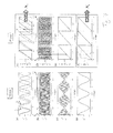
- Figure 7 illustrates exemplary signal curves and phase curves appearing in the SWA.
- Figures 7(a) and 7(b) illustrate the signals S a , S b obtained by demodulating the first and second laser light, respectively.
- Figure 7(c) illustrates the beating pattern generated by S a + S b .
- the synthetic phase ⁇ s having the periodicity of the beating pattern is illustrated in Figure 7(d) .
- Figures 7(e)-7(h) illustrate the processes P2 and P3 of the SWA as explained above.
- the coarse absolute distance x fti has already been determined, e.g., by SWA_P1 or another method for coarse absolute distance determination.
- the fringe number N s of the synthetic wavelength may be computed according to equation (21).
- the intermediate accurate absolute distance x s may then be calculated according to equation (22) based on the synthetic fringe number N s and the (possibly phase corrected) synthetic phase ⁇ s in, e.g. SWA_P2, see Figure 7(g) .
- the fringe number N b (or N a ) may be computed based on the intermediate absolute distance x s and equation (24), see Figures 7(f)-7(e) , and the high accuracy absolute distance x 0 may be computed based on the fringe number N b and a phase of the second wavelength light according to equation (25) - or based on the fringe number N a and a phase of the first wavelength light analogously to equation (25).
- the computation unit 170 is configured to calculate a high accuracy absolute distance x 0 based on the fringe number N b (or N a ) and a phase of the second wavelength ⁇ b (or a phase of the first wavelength ⁇ a ).
- SWA_P1, SWA_P2 and SWA_P3 are not required to be performed in combination.
- the coarse absolute distance x fti which is needed as an input variable, does not need to be determined by SWA_P1.
- the intermediate accurate absolute distance x s needed as an input variable may also be provided by a different process than SWA_P2. In some cases, the accuracy of SWA_P1 or SWA_P2 may be sufficient, and therefore, the following processes (SWA_P2 and SWA_P3 or SWA_P3) may not be needed.
- the CFNA provides another scheme to compute a high accuracy absolute distance x.
- no synthetic wavelength is used.
- basically only one of the two lasers 110, 120 must be tunable (at least if the correction process CP2 to obtain phase corrected values of ⁇ b is not performed or if such phase corrected values are obtained by other methods).
- both lasers are tunable, e.g. if more independent data sets are to be collected for obtaining higher accuracy or if a consistency check is desired.
- the wavelength sweep laser 110 e.g. laser A
- the displacement tracking laser 120 e.g. laser B
- the roles of both lasers as wavelength sweep laser (i.e. tunable wavelength operation) and displacement tracking laser (i.e. constant wavelength operation) may be interchanged during the course of the measurement.
- both laser wavelengths are modulated at two different frequencies so that they can be distinguished from each other in the computation unit 170.
- the same set-up as described above, e.g., with reference to devices 100, 200, can be used. That is, optical interferences in the Fabry-Pérot interferometer cavity 140 lead to photo measurement signals (in-phase signals and their quadrature signals) that can be determined independently for each of the two lasers.
- the correction processes CP1 and CP2 may have been performed in advance, e.g. during an initialization procedure as already described, such that, e.g., the LUT's are configured to correct the real phases ⁇ a , ⁇ b for their nonlinearities.
- the CFNA uses an extremum principle for determining a high accuracy absolute distance x.
- the CFNA may be based on recording fractional values of interferometric phases of both laser lights at start and/or stop points of wavelength sweeps, on establishing one or more sets of fringe number combinations based on a coarse knowledge of an absolute distance and on applying an extremum principle for electing a specific fringe number combination from each of the sets of fringe number combinations.
- the laser wavelengths of the first and second lasers 110, 120 may be set to start values ⁇ a,s and ⁇ b,s , respectively. This may be done by stabilizing the lasers 110, 120 to known wavelengths ⁇ a,s and ⁇ b,s , respectively, e.g. by using feedback loops and/or gas cells as described above.
- the index s refers to "start” and the index e refers to "end”.
- ⁇ a,s and ⁇ b,s are known to the desired accuracy.
- the cavity length e.g. the absolute distance x of the second resonator mirror 142, is unknown at the start of the initial measurement described below.
- fractional values 2 ⁇ a,s and 2 ⁇ b,s of the interferometric phases may be measured.
- These start fractional values 2 ⁇ a,s and 2 ⁇ b,s of both interferometric phases are recorded. This may be performed, e.g., independently from the quadrature signals originating from each of the lasers.
- the absolute phases i.e. the start fringe numbers N a,s and N b,s ) are unknown but the start fractional phase values 2 ⁇ a,s and 2 ⁇ b,s may be measured with high interferometric precision.
- the wavelength ⁇ a of the first laser 110 (laser A) is swept.
- the wavelength of the first laser 110 is shifted continuously to another precisely known wavelength value ⁇ a,e .
- the wavelength ⁇ b of the second laser 120 (laser B) may be maintained at a constant and exact value, e.g. at its stabilized start value ⁇ b,s . Shifting the wavelength of the first laser 110 is performed slow enough that the corresponding interferometric phase shift can be measured.
- the associated phase shift may be continuously recorded until the laser wavelength has reached its stable exact end value ⁇ a,e .
- the wavelength ⁇ a has reached its end value ⁇ a,e
- both the single value ⁇ a of the phase displacement of the light of the first laser 110 during the wavelength sweep as well as the single value ⁇ b of the phase displacement of the light of the second laser 120 during the wavelength sweep are recorded.
- the wavelength ⁇ b has been kept constant during this operation, a non-zero phase displacement ⁇ b will be solely due to a change ⁇ x in the cavity length x.
- the phase displacement ⁇ a results both from the intended wavelength shift caused by the wavelength sweep and from any change ⁇ x in the cavity length (e.g. a displacement ⁇ x of the target).
- equation (34) already solves the problem.
- the measured values of ⁇ a and ⁇ b may not be sufficiently exact and may deviate from the reality due to phase noise and other measurement errors inherent to interferometric displacement sensing.
- the effective wavelength ⁇ a is significantly longer than ⁇ a,s since the wavelength shift ⁇ a,e - ⁇ a,s is typically only a small fraction of ⁇ a,s .
- a leverage factor of ⁇ a / ⁇ a,s which may be about 10 3 . That is, an actual position error of 10 nm would lead to an error of 10 ⁇ m of the evaluated absolute distance x.
- the error of the evaluated absolute distance x may be far larger than the measurement pitch of ⁇ a /2p. Therefore, in reality, equation (34) may only provide for a coarse estimation of the absolute distance x.
- a determination of a coarse value of x may also be performed by processes different from CFNA_P3.
- a coarse absolute distance value of x is then input into the equations (42) and (43) to get coarse values of the fringe numbers N a,s , N b,s .
- the coarse value of x may be computed by CFNA_P3 or SWA_P2, however, also other procedures may be used to obtain the coarse absolute distance value x.
- N a , s + ⁇ a , s ⁇ ⁇ a , s 2 ⁇ p - N b , s + ⁇ b , s ⁇ ⁇ b , s 2 ⁇ p is calculated which is the condition of eliminating x between equations (42) and (43).
- the equation (46) is minimized over all possible combinations of [N a,s
- N' b,s ] provides the unknown value of x with high accuracy.
- CFNA_P5 In another process (P5) of the CFNA, which will be referred to as CFNA_P5 in the following, some others of the equations (42)-(45), namely e.g. equations (44)-(45) may be exploited to compute an accurate value of the absolute distance of x.
- CFNA_P5 may be performed instead of CFNA_P4 or in addition to CFNA_P4.
- a frequency sweep of the first laser 110 and a frequency sweep of the second laser 120 are performed to deliver two sets of data, which may then be exploited to compute an accurate value of x.
- the frequency sweep of the first laser 110 may be performed in accordance and, e.g., simultaneously with CFNA_P2, and reference is made to the corresponding description in order to avoid reiteration.
- the end fractional value 2 ⁇ a,e of the interferometric phase is recorded.
- the frequency sweep of the second laser 120 may be performed after the end of the frequency sweep of the first laser 110.
- the wavelength of the second laser 120 is shifted continuously to another precisely known wavelength value ⁇ b,e .
- the wavelength ⁇ a of the first laser 110 (laser A) may be maintained at a constant and exact value, e.g. at its stabilized end value ⁇ b,e .
- Shifting the wavelength of the second laser 120 is performed slow enough that the corresponding interferometric phase shift can be measured.
- the end fractional value 2 ⁇ b,e of the interferometric phase is recorded.
- the absolute phases i.e. the end fringe numbers N a,e and N b,e
- the end fractional values 2 ⁇ a,e and 2 ⁇ b,e of the interferometric phases may be measured with high interferometric precision.
- a coarse absolute distance value of x is then input into the equations (44) and (45) to get coarse values of the fringe numbers N a,e , N b,e .
- the coarse absolute distance value of x may have been computed in accordance with CFNA_P3 or SWA_P2, however, also other procedures may be used to obtain the coarse absolute distance value x.
- N a , e + ⁇ a , e ⁇ ⁇ a , e 2 ⁇ p - N b , e + ⁇ b , e ⁇ ⁇ b , e 2 ⁇ p may be calculated.
- an accurate value of the absolute distance x may be calculated from, e.g., equation (44) or equation (45).
- Equation (47) is minimized over all possible combinations of [N a,e
- N' b,e ] provides the unknown value of x with high accuracy based e.g. on equation (44) or (45).
- the device 100, 200 may be configured to measure a fractional phase of the interferometric first wavelength light at a known first wavelength ⁇ a and a fractional phase of the interferometric second wavelength light at a known second wavelength ⁇ b .
- the computation unit 170 may be configured to compute a plurality of possible combinations of [N a
- CFNA_P6 another process of the CFNA, which will be referred to as CFNA_P6 in the following
- the minimum combinations obtained in CFNA_P4 and CFNA_P5 or the absolute distance values x obtained in CFNA_P4 and CFNA_P5 may be combined.
- the accurate absolute distance value x(CFNA_P4) and the accurate absolute distance value x(CFNA_P5) may be combined, e.g., by averaging to derive a further absolute distance value x. Averaging could involve evaluating the distances of the minimum combinations from the 0 condition and weighting the average based on these distances.
- a consistency check may be performed on the basis of the sets of possible combinations or on the absolute distance values x obtained in CFNA_P4 and CFNA_P5.
- a predetermined threshold e.g. ⁇ /4 or ⁇ /8
- the device 100, 200 may be configured to measure two fractional phases of the interferometric first wavelength light at a known frequency sweep start first wavelength ⁇ a,s and a known frequency sweep end first wavelength ⁇ a,e , and to measure two fractional phases of the interferometric second wavelength light at a known frequency sweep start second wavelength ⁇ b,s and a known frequency sweep end second wavelength ⁇ b,e .
- the computation unit may be configured to compute two sets of possible combinations of [N a,s
- the computation unit 170 may be configured to determine a specific combination [N' a,s
- Figure 10 illustrates an interruption and full shutdown of an interferometer device at point A and, e.g. a few minutes or hours later, a system restart at point B.
- the object is subjected to a displacement caused, e.g., by external influences such as vibrations, etc.
- the device 100, 200 for absolute distance measurement is able to acquire an accurate absolute distance of the object at point B, i.e. when the system is turned back on and the measurement is resumed. This greatly improves the practical versatility of an interferometric position measurement device.
- the subsequent determination of x may be performed by applying a conventional incremental displacement measurement approach.
- Such incremental displacement measurement which is, e.g. described in EP 2 363 685 A1 , may merely require one laser (e.g. laser 110).
Priority Applications (4)
| Application Number | Priority Date | Filing Date | Title |
|---|---|---|---|
| EP13169159.4A EP2806246B1 (de) | 2013-05-24 | 2013-05-24 | Doppellaserinterferometer |
| DE202014101699.6U DE202014101699U1 (de) | 2013-05-24 | 2014-04-10 | Absolut-Entfernungs-Laserinterferometer |
| JP2014103601A JP6199801B2 (ja) | 2013-05-24 | 2014-05-19 | 絶対距離レーザ干渉計 |
| US14/284,756 US9829306B2 (en) | 2013-05-24 | 2014-05-22 | Absolute distance laser interferometer |
Applications Claiming Priority (1)
| Application Number | Priority Date | Filing Date | Title |
|---|---|---|---|
| EP13169159.4A EP2806246B1 (de) | 2013-05-24 | 2013-05-24 | Doppellaserinterferometer |
Publications (2)
| Publication Number | Publication Date |
|---|---|
| EP2806246A1 true EP2806246A1 (de) | 2014-11-26 |
| EP2806246B1 EP2806246B1 (de) | 2019-11-20 |
Family
ID=48463885
Family Applications (1)
| Application Number | Title | Priority Date | Filing Date |
|---|---|---|---|
| EP13169159.4A Active EP2806246B1 (de) | 2013-05-24 | 2013-05-24 | Doppellaserinterferometer |
Country Status (4)
| Country | Link |
|---|---|
| US (1) | US9829306B2 (de) |
| EP (1) | EP2806246B1 (de) |
| JP (1) | JP6199801B2 (de) |
| DE (1) | DE202014101699U1 (de) |
Cited By (2)
| Publication number | Priority date | Publication date | Assignee | Title |
|---|---|---|---|---|
| DE102016103109A1 (de) | 2016-02-23 | 2017-08-24 | Björn Habrich | Vermessung einer kavität mittels interferenzspektroskopie |
| US11385107B2 (en) | 2016-09-29 | 2022-07-12 | Halliburton Energy Services, Inc. | Distributed temperature sensing over extended temperature ranges |
Families Citing this family (21)
| Publication number | Priority date | Publication date | Assignee | Title |
|---|---|---|---|---|
| WO2016043850A2 (en) | 2014-07-30 | 2016-03-24 | Luna Innovations, Inc. | Methods and apparatus for interferometric interrogation of an optical sensor |
| US10247538B2 (en) | 2014-10-29 | 2019-04-02 | Bridger Photonics, Inc. | Accurate chirped synthetic wavelength interferometer |
| US9945740B2 (en) * | 2015-05-14 | 2018-04-17 | Kulite Semiconductor Products, Inc. | Two wavelength optical interferometric pressure switch and pressure transducers |
| DE102015110362B4 (de) | 2015-06-26 | 2018-01-18 | n-hands GmbH & Co. KG | Verfahren und Vorrichtung zur interferometrischen Absolutmessung einer Entfernung |
| WO2017046832A1 (en) | 2015-09-18 | 2017-03-23 | Hamamatsu Photonics K.K. | Optical distance measuring system |
| US9970756B2 (en) | 2015-10-06 | 2018-05-15 | Bridger Photonics, Inc. | High-sensitivity gas-mapping 3D imager and method of operation |
| WO2017163233A1 (en) * | 2016-03-22 | 2017-09-28 | B. G. Negev Technologies And Applications Ltd., At Ben-Gurion University | Frequency modulated multiple wavelength parallel phase shift interferometry |
| WO2018170478A1 (en) | 2017-03-16 | 2018-09-20 | Bridger Photonics, Inc. | Fmcw lidar methods and apparatuses including examples having feedback loops |
| US11422244B2 (en) | 2017-09-25 | 2022-08-23 | Bridger Photonics, Inc. | Digitization systems and techniques and examples of use in FMCW LiDAR methods and apparatuses |
| US11604280B2 (en) | 2017-10-02 | 2023-03-14 | Bridger Photonics, Inc. | Processing temporal segments of laser chirps and examples of use in FMCW LiDAR methods and apparatuses |
| WO2019079448A1 (en) | 2017-10-17 | 2019-04-25 | Bridger Photonics, Inc. | ROTARY OPTICAL REFLECTOR APPARATUSES AND METHODS |
| CA3082566A1 (en) | 2017-11-14 | 2019-05-23 | Bridger Photonics, Inc. | Apparatuses and methods for anomalous gas concentration detection |
| US11525737B2 (en) * | 2018-01-31 | 2022-12-13 | Asml Netherland B.V. | Wavelength tracking system, method to calibrate a wavelength tracking system, lithographic apparatus, method to determine an absolute position of a movable object, and interferometer system |
| DE102018208147A1 (de) * | 2018-05-24 | 2019-11-28 | Carl Zeiss Smt Gmbh | Messanordnung zur frequenszbasierten Positionsbestimmung einer Komponente |
| CN112204428B (zh) * | 2018-05-24 | 2024-03-22 | 三菱电机株式会社 | 光测距装置以及加工装置 |
| DE102018218488A1 (de) | 2018-10-29 | 2018-12-13 | Carl Zeiss Smt Gmbh | Messanordnung zur interferometrischen Absolutmessung des Abstandes zwischen zwei Komponenten in einem optischen System für die Mikrolithographie |
| CN111121651A (zh) | 2018-10-31 | 2020-05-08 | 财团法人工业技术研究院 | 光学测量稳定性控制系统 |
| CN110174058B (zh) * | 2019-06-06 | 2020-06-23 | 浙江理工大学 | 动态偏频锁定式正弦频率扫描干涉绝对测距装置和方法 |
| CN112667966B (zh) * | 2020-12-18 | 2022-05-20 | 清华大学 | 原子干涉陀螺仪信号解算方法、装置、计算机设备和存储介质 |
| CN114924281B (zh) * | 2022-07-19 | 2022-11-04 | 天津大学四川创新研究院 | 一种基于h13c14n气体池的调频连续波同时测距和测速方法及系统 |
| CN115327515B (zh) * | 2022-08-10 | 2023-04-18 | 哈尔滨工业大学 | 一种基于相位传递的双扫频干涉动态测量系统及测量方法 |
Citations (5)
| Publication number | Priority date | Publication date | Assignee | Title |
|---|---|---|---|---|
| EP0260894A1 (de) * | 1986-09-12 | 1988-03-23 | Cogent Limited | Faseroptisches Messsystem |
| US20100259760A1 (en) * | 2007-10-04 | 2010-10-14 | Attocube Systems Ag | Device for position detection |
| US20110205523A1 (en) * | 2008-09-11 | 2011-08-25 | Nikon Metrology N.V. | Compact fiber optic geometry for a counter chirp fmcw coherent laser radar |
| EP2363685A1 (de) | 2010-02-09 | 2011-09-07 | Attocube Systems AG | Vorrichtung zur Positionserfassung mit konfokalem Fabry-Perot Interferometer |
| EP2589923A1 (de) * | 2011-11-01 | 2013-05-08 | Canon Kabushiki Kaisha | Frequenz-Scanning-Interferrometer mit entgegengesetzter Frequenzmodulation |
Family Cites Families (12)
| Publication number | Priority date | Publication date | Assignee | Title |
|---|---|---|---|---|
| FR2468099A1 (fr) * | 1979-10-17 | 1981-04-30 | Anvar | Procede et appareil d'interferometrie laser a deux longueurs d'ondes |
| US4355899A (en) | 1980-05-22 | 1982-10-26 | The United States Of America As Represented By The Secretary Of The Air Force | Interferometric distance measurement method |
| US4830486A (en) * | 1984-03-16 | 1989-05-16 | Goodwin Frank E | Frequency modulated lasar radar |
| JPH0749922B2 (ja) * | 1987-08-05 | 1995-05-31 | 松下電器産業株式会社 | 光計測装置 |
| JP2808136B2 (ja) * | 1989-06-07 | 1998-10-08 | キヤノン株式会社 | 測長方法及び装置 |
| JP3400503B2 (ja) * | 1993-10-26 | 2003-04-28 | 松下電工株式会社 | 干渉測長器 |
| JP4443939B2 (ja) * | 2004-01-13 | 2010-03-31 | 日本信号株式会社 | 受信時刻計測装置及びこれを用いた距離計測装置 |
| US7292347B2 (en) * | 2005-08-01 | 2007-11-06 | Mitutoyo Corporation | Dual laser high precision interferometer |
| US7864331B2 (en) * | 2006-11-17 | 2011-01-04 | Fujifilm Corporation | Optical coherence tomographic imaging apparatus |
| DE102008033942B3 (de) | 2008-07-18 | 2010-04-08 | Luphos Gmbh | Faseroptisches Mehrwellenlängeninterferometer (MWLI) zur absoluten Vermessung von Abständen und Topologien von Oberflächen in großem Arbeitsabstand |
| JP5550384B2 (ja) * | 2010-03-01 | 2014-07-16 | キヤノン株式会社 | 光波干渉計測装置 |
| JP6298999B2 (ja) | 2013-06-28 | 2018-03-28 | 株式会社デンケン | 呈色測定装置および呈色測定プログラム |
-
2013
- 2013-05-24 EP EP13169159.4A patent/EP2806246B1/de active Active
-
2014
- 2014-04-10 DE DE202014101699.6U patent/DE202014101699U1/de not_active Expired - Lifetime
- 2014-05-19 JP JP2014103601A patent/JP6199801B2/ja active Active
- 2014-05-22 US US14/284,756 patent/US9829306B2/en active Active
Patent Citations (5)
| Publication number | Priority date | Publication date | Assignee | Title |
|---|---|---|---|---|
| EP0260894A1 (de) * | 1986-09-12 | 1988-03-23 | Cogent Limited | Faseroptisches Messsystem |
| US20100259760A1 (en) * | 2007-10-04 | 2010-10-14 | Attocube Systems Ag | Device for position detection |
| US20110205523A1 (en) * | 2008-09-11 | 2011-08-25 | Nikon Metrology N.V. | Compact fiber optic geometry for a counter chirp fmcw coherent laser radar |
| EP2363685A1 (de) | 2010-02-09 | 2011-09-07 | Attocube Systems AG | Vorrichtung zur Positionserfassung mit konfokalem Fabry-Perot Interferometer |
| EP2589923A1 (de) * | 2011-11-01 | 2013-05-08 | Canon Kabushiki Kaisha | Frequenz-Scanning-Interferrometer mit entgegengesetzter Frequenzmodulation |
Cited By (3)
| Publication number | Priority date | Publication date | Assignee | Title |
|---|---|---|---|---|
| DE102016103109A1 (de) | 2016-02-23 | 2017-08-24 | Björn Habrich | Vermessung einer kavität mittels interferenzspektroskopie |
| DE102016103109B4 (de) | 2016-02-23 | 2018-07-26 | Björn Habrich | Vermessung einer kavität mittels interferenzspektroskopie |
| US11385107B2 (en) | 2016-09-29 | 2022-07-12 | Halliburton Energy Services, Inc. | Distributed temperature sensing over extended temperature ranges |
Also Published As
| Publication number | Publication date |
|---|---|
| US20150019160A1 (en) | 2015-01-15 |
| JP6199801B2 (ja) | 2017-09-20 |
| EP2806246B1 (de) | 2019-11-20 |
| US9829306B2 (en) | 2017-11-28 |
| JP2014228545A (ja) | 2014-12-08 |
| DE202014101699U1 (de) | 2014-07-17 |
Similar Documents
| Publication | Publication Date | Title |
|---|---|---|
| EP2806246B1 (de) | Doppellaserinterferometer | |
| JP5265918B2 (ja) | モード選択同調器からの光フィードバック | |
| EP2816315B1 (de) | Interferometrische Bestimmung der Abstandsänderung mit Laserdiode, breitbandiger Detektion und schneller Signalverarbeitung | |
| Meiners-Hagen et al. | Multi-wavelength interferometry for length measurements using diode lasers | |
| US8363226B2 (en) | Optical interference measuring apparatus | |
| US11067690B2 (en) | Measuring apparatus comprising an interferometer and an absorption medium defining a dense line spectrum | |
| JP2009198477A (ja) | 光周波数発生器を用いた絶対距離測定方法及びシステム | |
| JPH039202A (ja) | 測長方法及び装置 | |
| Thurner et al. | Absolute distance sensing by two laser optical interferometry | |
| JP6019360B2 (ja) | 光ヘテロダイン距離計 | |
| Ishii | Recent developments in laser-diode interferometry | |
| JP6264547B2 (ja) | 光信号生成装置、距離測定装置、分光特性測定装置、周波数特性測定装置及び光信号生成方法 | |
| JP5421013B2 (ja) | 位置決め装置及び位置決め方法 | |
| JPH01205486A (ja) | 半導体レ−ザの波長安定化装置 | |
| US9857160B1 (en) | Multi-mode frequency sweeping interferometer and method of using same | |
| US4797552A (en) | Apparatus and method for locating the direction of an atomic beam | |
| US11885607B2 (en) | Device for interferometric distance measurement | |
| Wiseman | Novel applications and stabilisation for widely wavelength modulated laser interferometry for precision dimensional metrology. | |
| JPH0763506A (ja) | 干渉測長器 | |
| JPH08159710A (ja) | 光干渉式位置計測装置 | |
| WO2009081121A1 (en) | Distance measurement | |
| Pollinger et al. | Measurements of absolute long distances | |
| Kajima et al. | Self-zooming stable stage with sub-nm resolution using femtosecond frequency comb | |
| Suzuki et al. | Displacement measurement with a dual-colored sinusoidal phase-modulating interferometer |
Legal Events
| Date | Code | Title | Description |
|---|---|---|---|
| PUAI | Public reference made under article 153(3) epc to a published international application that has entered the european phase |
Free format text: ORIGINAL CODE: 0009012 |
|
| 17P | Request for examination filed |
Effective date: 20130524 |
|
| AK | Designated contracting states |
Kind code of ref document: A1 Designated state(s): AL AT BE BG CH CY CZ DE DK EE ES FI FR GB GR HR HU IE IS IT LI LT LU LV MC MK MT NL NO PL PT RO RS SE SI SK SM TR |
|
| AX | Request for extension of the european patent |
Extension state: BA ME |
|
| R17P | Request for examination filed (corrected) |
Effective date: 20150108 |
|
| RBV | Designated contracting states (corrected) |
Designated state(s): AL AT BE BG CH CY CZ DE DK EE ES FI FR GB GR HR HU IE IS IT LI LT LU LV MC MK MT NL NO PL PT RO RS SE SI SK SM TR |
|
| GRAP | Despatch of communication of intention to grant a patent |
Free format text: ORIGINAL CODE: EPIDOSNIGR1 |
|
| STAA | Information on the status of an ep patent application or granted ep patent |
Free format text: STATUS: GRANT OF PATENT IS INTENDED |
|
| INTG | Intention to grant announced |
Effective date: 20190614 |
|
| GRAS | Grant fee paid |
Free format text: ORIGINAL CODE: EPIDOSNIGR3 |
|
| GRAA | (expected) grant |
Free format text: ORIGINAL CODE: 0009210 |
|
| STAA | Information on the status of an ep patent application or granted ep patent |
Free format text: STATUS: THE PATENT HAS BEEN GRANTED |
|
| AK | Designated contracting states |
Kind code of ref document: B1 Designated state(s): AL AT BE BG CH CY CZ DE DK EE ES FI FR GB GR HR HU IE IS IT LI LT LU LV MC MK MT NL NO PL PT RO RS SE SI SK SM TR |
|
| REG | Reference to a national code |
Ref country code: GB Ref legal event code: FG4D |
|
| REG | Reference to a national code |
Ref country code: CH Ref legal event code: EP |
|
| REG | Reference to a national code |
Ref country code: IE Ref legal event code: FG4D |
|
| REG | Reference to a national code |
Ref country code: AT Ref legal event code: REF Ref document number: 1204670 Country of ref document: AT Kind code of ref document: T Effective date: 20191215 |
|
| REG | Reference to a national code |
Ref country code: DE Ref legal event code: R096 Ref document number: 602013063038 Country of ref document: DE |
|
| REG | Reference to a national code |
Ref country code: CH Ref legal event code: NV Representative=s name: SERVOPATENT GMBH, CH |
|
| REG | Reference to a national code |
Ref country code: NL Ref legal event code: FP |
|
| REG | Reference to a national code |
Ref country code: LT Ref legal event code: MG4D |
|
| PG25 | Lapsed in a contracting state [announced via postgrant information from national office to epo] |
Ref country code: LT Free format text: LAPSE BECAUSE OF FAILURE TO SUBMIT A TRANSLATION OF THE DESCRIPTION OR TO PAY THE FEE WITHIN THE PRESCRIBED TIME-LIMIT Effective date: 20191120 Ref country code: GR Free format text: LAPSE BECAUSE OF FAILURE TO SUBMIT A TRANSLATION OF THE DESCRIPTION OR TO PAY THE FEE WITHIN THE PRESCRIBED TIME-LIMIT Effective date: 20200221 Ref country code: NO Free format text: LAPSE BECAUSE OF FAILURE TO SUBMIT A TRANSLATION OF THE DESCRIPTION OR TO PAY THE FEE WITHIN THE PRESCRIBED TIME-LIMIT Effective date: 20200220 Ref country code: BG Free format text: LAPSE BECAUSE OF FAILURE TO SUBMIT A TRANSLATION OF THE DESCRIPTION OR TO PAY THE FEE WITHIN THE PRESCRIBED TIME-LIMIT Effective date: 20200220 Ref country code: FI Free format text: LAPSE BECAUSE OF FAILURE TO SUBMIT A TRANSLATION OF THE DESCRIPTION OR TO PAY THE FEE WITHIN THE PRESCRIBED TIME-LIMIT Effective date: 20191120 Ref country code: SE Free format text: LAPSE BECAUSE OF FAILURE TO SUBMIT A TRANSLATION OF THE DESCRIPTION OR TO PAY THE FEE WITHIN THE PRESCRIBED TIME-LIMIT Effective date: 20191120 Ref country code: LV Free format text: LAPSE BECAUSE OF FAILURE TO SUBMIT A TRANSLATION OF THE DESCRIPTION OR TO PAY THE FEE WITHIN THE PRESCRIBED TIME-LIMIT Effective date: 20191120 Ref country code: ES Free format text: LAPSE BECAUSE OF FAILURE TO SUBMIT A TRANSLATION OF THE DESCRIPTION OR TO PAY THE FEE WITHIN THE PRESCRIBED TIME-LIMIT Effective date: 20191120 |
|
| PG25 | Lapsed in a contracting state [announced via postgrant information from national office to epo] |
Ref country code: RS Free format text: LAPSE BECAUSE OF FAILURE TO SUBMIT A TRANSLATION OF THE DESCRIPTION OR TO PAY THE FEE WITHIN THE PRESCRIBED TIME-LIMIT Effective date: 20191120 Ref country code: IS Free format text: LAPSE BECAUSE OF FAILURE TO SUBMIT A TRANSLATION OF THE DESCRIPTION OR TO PAY THE FEE WITHIN THE PRESCRIBED TIME-LIMIT Effective date: 20200320 Ref country code: HR Free format text: LAPSE BECAUSE OF FAILURE TO SUBMIT A TRANSLATION OF THE DESCRIPTION OR TO PAY THE FEE WITHIN THE PRESCRIBED TIME-LIMIT Effective date: 20191120 |
|
| REG | Reference to a national code |
Ref country code: CH Ref legal event code: PCAR Free format text: NEW ADDRESS: WANNERSTRASSE 9/1, 8045 ZUERICH (CH) |
|
| PG25 | Lapsed in a contracting state [announced via postgrant information from national office to epo] |
Ref country code: AL Free format text: LAPSE BECAUSE OF FAILURE TO SUBMIT A TRANSLATION OF THE DESCRIPTION OR TO PAY THE FEE WITHIN THE PRESCRIBED TIME-LIMIT Effective date: 20191120 |
|
| PG25 | Lapsed in a contracting state [announced via postgrant information from national office to epo] |
Ref country code: DK Free format text: LAPSE BECAUSE OF FAILURE TO SUBMIT A TRANSLATION OF THE DESCRIPTION OR TO PAY THE FEE WITHIN THE PRESCRIBED TIME-LIMIT Effective date: 20191120 Ref country code: PT Free format text: LAPSE BECAUSE OF FAILURE TO SUBMIT A TRANSLATION OF THE DESCRIPTION OR TO PAY THE FEE WITHIN THE PRESCRIBED TIME-LIMIT Effective date: 20200412 Ref country code: EE Free format text: LAPSE BECAUSE OF FAILURE TO SUBMIT A TRANSLATION OF THE DESCRIPTION OR TO PAY THE FEE WITHIN THE PRESCRIBED TIME-LIMIT Effective date: 20191120 Ref country code: CZ Free format text: LAPSE BECAUSE OF FAILURE TO SUBMIT A TRANSLATION OF THE DESCRIPTION OR TO PAY THE FEE WITHIN THE PRESCRIBED TIME-LIMIT Effective date: 20191120 Ref country code: RO Free format text: LAPSE BECAUSE OF FAILURE TO SUBMIT A TRANSLATION OF THE DESCRIPTION OR TO PAY THE FEE WITHIN THE PRESCRIBED TIME-LIMIT Effective date: 20191120 |
|
| REG | Reference to a national code |
Ref country code: AT Ref legal event code: MK05 Ref document number: 1204670 Country of ref document: AT Kind code of ref document: T Effective date: 20191120 |
|
| REG | Reference to a national code |
Ref country code: DE Ref legal event code: R097 Ref document number: 602013063038 Country of ref document: DE |
|
| PG25 | Lapsed in a contracting state [announced via postgrant information from national office to epo] |
Ref country code: SM Free format text: LAPSE BECAUSE OF FAILURE TO SUBMIT A TRANSLATION OF THE DESCRIPTION OR TO PAY THE FEE WITHIN THE PRESCRIBED TIME-LIMIT Effective date: 20191120 Ref country code: SK Free format text: LAPSE BECAUSE OF FAILURE TO SUBMIT A TRANSLATION OF THE DESCRIPTION OR TO PAY THE FEE WITHIN THE PRESCRIBED TIME-LIMIT Effective date: 20191120 |
|
| PLBE | No opposition filed within time limit |
Free format text: ORIGINAL CODE: 0009261 |
|
| STAA | Information on the status of an ep patent application or granted ep patent |
Free format text: STATUS: NO OPPOSITION FILED WITHIN TIME LIMIT |
|
| 26N | No opposition filed |
Effective date: 20200821 |
|
| PG25 | Lapsed in a contracting state [announced via postgrant information from national office to epo] |
Ref country code: SI Free format text: LAPSE BECAUSE OF FAILURE TO SUBMIT A TRANSLATION OF THE DESCRIPTION OR TO PAY THE FEE WITHIN THE PRESCRIBED TIME-LIMIT Effective date: 20191120 Ref country code: PL Free format text: LAPSE BECAUSE OF FAILURE TO SUBMIT A TRANSLATION OF THE DESCRIPTION OR TO PAY THE FEE WITHIN THE PRESCRIBED TIME-LIMIT Effective date: 20191120 Ref country code: AT Free format text: LAPSE BECAUSE OF FAILURE TO SUBMIT A TRANSLATION OF THE DESCRIPTION OR TO PAY THE FEE WITHIN THE PRESCRIBED TIME-LIMIT Effective date: 20191120 |
|
| PG25 | Lapsed in a contracting state [announced via postgrant information from national office to epo] |
Ref country code: MC Free format text: LAPSE BECAUSE OF FAILURE TO SUBMIT A TRANSLATION OF THE DESCRIPTION OR TO PAY THE FEE WITHIN THE PRESCRIBED TIME-LIMIT Effective date: 20191120 Ref country code: IT Free format text: LAPSE BECAUSE OF FAILURE TO SUBMIT A TRANSLATION OF THE DESCRIPTION OR TO PAY THE FEE WITHIN THE PRESCRIBED TIME-LIMIT Effective date: 20191120 |
|
| REG | Reference to a national code |
Ref country code: BE Ref legal event code: MM Effective date: 20200531 |
|
| PG25 | Lapsed in a contracting state [announced via postgrant information from national office to epo] |
Ref country code: LU Free format text: LAPSE BECAUSE OF NON-PAYMENT OF DUE FEES Effective date: 20200524 |
|
| PG25 | Lapsed in a contracting state [announced via postgrant information from national office to epo] |
Ref country code: IE Free format text: LAPSE BECAUSE OF NON-PAYMENT OF DUE FEES Effective date: 20200524 |
|
| PG25 | Lapsed in a contracting state [announced via postgrant information from national office to epo] |
Ref country code: BE Free format text: LAPSE BECAUSE OF NON-PAYMENT OF DUE FEES Effective date: 20200531 |
|
| PG25 | Lapsed in a contracting state [announced via postgrant information from national office to epo] |
Ref country code: TR Free format text: LAPSE BECAUSE OF FAILURE TO SUBMIT A TRANSLATION OF THE DESCRIPTION OR TO PAY THE FEE WITHIN THE PRESCRIBED TIME-LIMIT Effective date: 20191120 Ref country code: MT Free format text: LAPSE BECAUSE OF FAILURE TO SUBMIT A TRANSLATION OF THE DESCRIPTION OR TO PAY THE FEE WITHIN THE PRESCRIBED TIME-LIMIT Effective date: 20191120 Ref country code: CY Free format text: LAPSE BECAUSE OF FAILURE TO SUBMIT A TRANSLATION OF THE DESCRIPTION OR TO PAY THE FEE WITHIN THE PRESCRIBED TIME-LIMIT Effective date: 20191120 |
|
| PG25 | Lapsed in a contracting state [announced via postgrant information from national office to epo] |
Ref country code: MK Free format text: LAPSE BECAUSE OF FAILURE TO SUBMIT A TRANSLATION OF THE DESCRIPTION OR TO PAY THE FEE WITHIN THE PRESCRIBED TIME-LIMIT Effective date: 20191120 |
|
| PGFP | Annual fee paid to national office [announced via postgrant information from national office to epo] |
Ref country code: NL Payment date: 20230519 Year of fee payment: 11 Ref country code: FR Payment date: 20230517 Year of fee payment: 11 Ref country code: DE Payment date: 20230217 Year of fee payment: 11 Ref country code: CH Payment date: 20230605 Year of fee payment: 11 |
|
| PGFP | Annual fee paid to national office [announced via postgrant information from national office to epo] |
Ref country code: GB Payment date: 20230522 Year of fee payment: 11 |