EP2805873A2 - Handhabung der Lenkung mit Kurzschluss von Batterie zur Masse - Google Patents
Handhabung der Lenkung mit Kurzschluss von Batterie zur Masse Download PDFInfo
- Publication number
- EP2805873A2 EP2805873A2 EP14001556.1A EP14001556A EP2805873A2 EP 2805873 A2 EP2805873 A2 EP 2805873A2 EP 14001556 A EP14001556 A EP 14001556A EP 2805873 A2 EP2805873 A2 EP 2805873A2
- Authority
- EP
- European Patent Office
- Prior art keywords
- power source
- node
- controller
- short
- secondary power
- Prior art date
- Legal status (The legal status is an assumption and is not a legal conclusion. Google has not performed a legal analysis and makes no representation as to the accuracy of the status listed.)
- Granted
Links
Images


Classifications
-
- B—PERFORMING OPERATIONS; TRANSPORTING
- B62—LAND VEHICLES FOR TRAVELLING OTHERWISE THAN ON RAILS
- B62D—MOTOR VEHICLES; TRAILERS
- B62D6/00—Arrangements for automatically controlling steering depending on driving conditions sensed and responded to, e.g. control circuits
-
- B—PERFORMING OPERATIONS; TRANSPORTING
- B62—LAND VEHICLES FOR TRAVELLING OTHERWISE THAN ON RAILS
- B62D—MOTOR VEHICLES; TRAILERS
- B62D5/00—Power-assisted or power-driven steering
- B62D5/04—Power-assisted or power-driven steering electrical, e.g. using an electric servo-motor connected to, or forming part of, the steering gear
- B62D5/0457—Power-assisted or power-driven steering electrical, e.g. using an electric servo-motor connected to, or forming part of, the steering gear characterised by control features of the drive means as such
- B62D5/0481—Power-assisted or power-driven steering electrical, e.g. using an electric servo-motor connected to, or forming part of, the steering gear characterised by control features of the drive means as such monitoring the steering system, e.g. failures
-
- H—ELECTRICITY
- H02—GENERATION; CONVERSION OR DISTRIBUTION OF ELECTRIC POWER
- H02H—EMERGENCY PROTECTIVE CIRCUIT ARRANGEMENTS
- H02H3/00—Emergency protective circuit arrangements for automatic disconnection directly responsive to an undesired change from normal electric working condition with or without subsequent reconnection ; integrated protection
- H02H3/16—Emergency protective circuit arrangements for automatic disconnection directly responsive to an undesired change from normal electric working condition with or without subsequent reconnection ; integrated protection responsive to fault current to earth, frame or mass
Definitions
- the present disclosure generally relates to steering systems, and more particularly, to systems and methods for providing redundant control of a steering system.
- Steering systems are commonly used in a variety of different fields to provide an operator with directional control of a vehicle, machine, or the like.
- electrical means such as electro-hydraulic or steer-by-wire steering systems, which convert operator input into mechanical or directional changes in the vehicle or machine.
- electro-hydraulic or steer-by-wire steering systems which convert operator input into mechanical or directional changes in the vehicle or machine.
- any significant interruption to the power source may limit or completely disable the operator's ability to control or steer the vehicle or machine.
- One known electrical failure occurs when there is a short circuit in the primary power source.
- a cable connected to a positive terminal of the batteries may short-circuit or come into contact to ground or a ground-wire.
- Such shorting of the primary power source can disable power to all electrical components connected thereto, including the associated electronic controller, or the electronic control module (ECM) that is, among other things, responsible for managing operation of the steering system. Without an operating ECM and without a fully functioning steering system, the operator may be unable to steer the vehicle or machine into more convenient or safer positions until the failure is repaired.
- ECM electronice control module
- a solution to the shorting problem implements shielded battery cables configured to provide early indications of wear potentially leading to short-circuit conditions.
- Shielded battery cables provide the battery cables with an extra insulating layer of protection, as well as conductivity therethrough which varies in response to any significant wear in the cable shielding.
- the shielded battery cables may be configured such that corresponding changes in the conductivity thereof trigger visual and/or audible indicators designed to warn the operator of such conditions.
- a method of providing redundant control of a steering system using one of a first controller and a second controller may provide an interface circuit between at least a first node and a second node of the steering system, where the first node may be electrically disposed between a primary power source and the first controller, and the second node may be electrically disposed between a secondary power source and the second controller.
- the method may further automatically engage a self-test of the primary power source and the secondary power source upon machine startup, engage the interface circuit to isolate the short from the secondary power source and engage the second controller to operate the steering system in response to a short at the first node, and engage the interface circuit to isolate the short from the primary power source and enable the first controller to operate the steering system in response to a short at the second node.
- a redundancy system for a steering system having a primary controller and a primary power source.
- the redundancy system may include a secondary controller coupled to a secondary power source and configured to manage control of the steering system, and an interface circuit disposed between at least a first node and a second node.
- the first node may be in electrical communication with the primary power source
- the second node may be in electrical communication with the secondary power source.
- the interface circuit may be configured to selectively engage a self-test of the primary power source and the secondary power source, isolate a short at the first node from the secondary power source, and isolate a short at the second node from the primary power source.
- a control system may include a primary power source in communication with a common bus associated with the control system, a secondary power source in selective communication with the common bus, a first controller in communication with a first node of the common bus configured to manage control of a steering system, a second controller in communication with a second node of the common bus configured to manage control of the steering system, and an interface circuit disposed between the first node and the second node.
- the interface circuit may include a blocking device configured to isolate a short at the first node from the secondary power source, a fusible link configured to isolate a short at the second node from the primary power source, and a self-test element configured to selectively engage a self-test of the primary power source and the secondary power source.
- a machine 100 for example, in the form of a motor grader is illustrated.
- the machine 100 may alternatively include any machine or vehicle that is steerable and performs some type of operation associated with an industry such as mining, construction, farming, transportation, or any other industry known in the art.
- the machine 100 may be a wheel loader, a tractor, a transport vehicle, such as truck, or the like.
- the representations of the various mechanisms presented herein are generic and are meant to encompass all possible mechanisms or devices used to convey an operator's commands to a machine, including, for example, joystick operation.
- the machine 100 may generally include a control system 102 for a steering mechanism or steering system 104 associated with the machine 100.
- the steering system 104 may manage operation of the steering capabilities of the machine 100 based on and according to input provided by an operator of the machine 100. Steering input may be provided, for example, using one or more joysticks, one or more steering wheels, or any other suitable means enabling an operator to steer and/or operate the machine 100.
- the steering system 104 may alternatively or additionally steer and operate the machine 100 in response to steering input provided remotely or off-site through electronic interfaces, controllers, and the like.
- the steering system 104 may implement fully or at least partially electrical mechanisms for steering the machine 100, such as electro-hydraulic or steer-by-wire steering systems, which convert mechanical and/or electrical operator input into mechanical or directional changes in the machine 100.
- the control system 102 may further provide redundancy to the steering system 104 using, for example, a first controller 106, a primary power source 108, a second controller 110, a secondary power source 112, an interface circuit 114, among others.
- the first and second controllers 106, 110 may ordinarily be powered by an alternator of the machine 100, and during fault conditions, the first and second controllers 106, 110 may be selectively powered by one of the primary and secondary power sources 108, 112 of the control system 102.
- Each of the first and second controllers 106, 110 may be configured to independently operate according to one or more predetermined algorithms which, among other things, enable any one of the controllers 106, 110 to at least temporarily manage control of the associated steering system 104.
- each of the first and second controllers 106, 110 may be implemented using one or more of a processor, a microprocessor, a microcontroller, an electronic control module (ECM), a digital signal processor (DSP), a field-programmable gate array (FPGA), an electronic control unit (ECU), or any other suitable means for managing operation of the steering system 104 associated with the machine 100.
- each of the primary power source 108 and the secondary power source 112 of FIG. 1 may employ any one or more of a variety of known power sources or energy storage devices, such as batteries, capable of selectively supplying direct current (DC) power to a corresponding one of the first controller 106 and the second controller 110 as needed.
- DC direct current
- the interface circuit 114 may be generally disposed in electrical communication between at least the first controller 106 and the second controller 110, and configured to appropriately isolate any short-circuit conditions which may occur along the lines interconnecting the power sources 108, 112 and the controllers 106, 110.
- the first controller 106 may be electrically coupled to the primary power source 108, depicted as series-connected batteries, through a first node 116
- the second controller 110 may be electrically coupled to the secondary power source 112, also shown as series-connected batteries, through a second node 118.
- first node 116 may be disposed anywhere along a common bus 120 extending between the first controller 106 and a positive terminal 122 of the primary power source 108, while the second node 118 may be disposed along any point between the second controller 110 and a positive terminal 124 of the secondary power source 112.
- the interface circuit 114 may be electrically coupled in between the first node 116 and the second node 118 as shown.
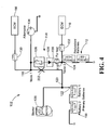
- the implementation of the interface circuit 114 of FIG. 2 may employ at least one fusible link 126 and at least one blocking device 128 disposed in series relative to one another and in between the first and second nodes 116, 118.
- the fusible link 126 may employ a fuse, a breaker, or any other known electrical device or component suitable for disconnecting, or opening, an electrical connection between the first node 116 and the second node 118 in the event of an over-current condition therethrough.
- the blocking device 128 may employ a fuse, a diode, a transistor, a switch, a breaker, or any other known electrical device or component suitable for restricting electrical current therethrough to flow from the second node 118 toward the first node 116.
- the control system 102 may further employ one or more protective elements 130, 132, for example, disposed between the first node 116 and the first controller 106, and between the second node 118 and the second controller 110.
- the protective elements 130, 132 may implement, for example, a breaker, a switch, a fuse, or any other suitable device adapted to automatically cause an open circuit and protect components of the control system 102 from short-circuit conditions, over-current conditions, or other electrical fault conditions.
- each of the protective elements 130, 132 may be configured with a current limit which approximates a current limit of the fusible link 126.
- the control system 102 of FIG. 2 may be coupled to an alternator 134 and a starter mechanism 136 associated with the machine 100.
- the alternator 134 may serve to convert mechanical or rotational input sourced by a prime mover, such as an engine, of the machine 100 into DC voltage that may be supplied to any variety of loads connected to the common bus 120.
- energy sourced by the alternator 134 and through the common bus 120 may be supplied to any of the first and second controllers 106, 110, thereby enabling proper control of at least steering system 104.
- the starter mechanism 136 may include a starter motor, or any other suitable device for initially powering the machine 100, the control system 102 and the steering system 104, among others.
- the interface circuit 114 of FIG. 2 may further include a self-test element 138, for example, electrically disposed between the first node 116 and the second node 118 as shown.
- the self-test element 138 may be used to ensure proper functionality of the redundant control system 102, and to pre-emptively test for or diagnose any fault conditions therein. More specifically, the self-test element 138 may enable the controllers 106, 110 to assess the state of each of the primary and secondary power sources 108, 112, and determine the ability of the power sources 108, 112 to properly function and backup the control system 102 in the event of a short-circuit or related fault condition.
- the self-test element 138 may employ one or more of a relay, a switch, or any other electrically controllable element that is selectively engageable between at least an opened state and a closed state.
- the self-test element 138 may be engaged manually, for example, in response to user input, and/or automatically, for example, upon every startup or in periodic cycles.
- the manner in which the self-test element 138 is engaged may be preprogrammed within one or more of the first and second controllers 106, 110, or any other control unit of the associated machine 100.
- controllers 106, 110 may be configured to engage the self-test element 138 to electrically open upon machine startup or after engine start so as to isolate the power sources 108, 112, and determine if the voltages thereof meet the minimum required to appropriately support the controllers 106, 110, for instance, during a fault condition.
- Other features not discussed or disclosed in the drawings will be apparent to those skilled in the art without departing from the scope of the appended claims.
- step 200-1 the method 200 may provide an interface circuit 114, as shown in FIG. 2 for example, that is electrically disposed between at least the first node 116 and the second node 118 of the control system 102, where the first node 116 is disposed between the first controller 106 and the primary power source 108 and the second node 118 is disposed between the second controller 110 and the secondary power source 112.
- the control system 102 may be configured to engage a self-test during step 200-2 if the machine 100 is determined to be at startup or after engine start.
- one or more of the controllers 106, 110 or any other associated control unit may be configured to, for example, automatically engage the self-test element 138 of FIG. 2 to cause an open circuit thereacross.
- the control system 102 may be able to substantially isolate and diagnose each of the primary and secondary power sources 108, 112 in step 200-3. If the DC voltage supplied across either of the power sources 108, 112 is detected to be less than the minimum bus voltage required to support the controllers 106, 108 during a fault condition, an error or appropriate warning may be triggered indicating the deficiency during step 200-4.
- the control system 102 may proceed to maintain normal operating conditions in step 200-5.
- the self-test may be automatically engaged based on other criteria, such as upon the expiration of a predefined time limit or based upon internal counters.
- the self-test may also be engaged manually and in response to user input.
- the control system 102 and interface circuit 114 may continue maintaining normal operating conditions in step 200-5 until a fault condition is determined. If a fault condition, such as a short-circuit to any of the primary or secondary power sources 108, 112, is detected, the control system 102 may proceed to either of steps 200-6 and 200-7 to respond accordingly. Specifically, if a short-circuit condition occurs in association with the first node 116, the interface circuit 114 may be configured to isolate the short-circuit from the second node 118, the second controller 110 and the secondary power source 112 in step 200-6. As illustrated in FIG.
- the voltage at the first node 116 as well as the voltage supplied to the first controller 106 may drop to zero.
- electrical current may be prevented from flowing from the secondary power source 112 and toward the first node 116 by the diode or blocking device 128, thereby isolating the short-circuit 202 from both the second controller 110 and the secondary power source 112.
- the second controller 110 which is operatively independent from the first controller 106, is isolated from the short-circuit 202 and because the power supplied thereto by the secondary power source 112 remains substantially uninterrupted, the second controller 110 may be engaged in step 200-7 to maintain normal operation of the steering system 102.
- the interface circuit 114 may be configured to isolate the short-circuit from the first node 116, the first controller 106 and the first power source 108 in step 200-8.
- the voltage at the second node 118 as well as the voltage to the second controller 110 may drop to zero.
- This short-circuit 202 may not only disable any operability of the second controller 110, but it may also create a potential difference with the first node 116 and the common bus 120.
- the fusible link 126 may serve as a fuse configured to disconnect, or create an open-circuit between the first and second nodes 116, 118, if the current flow therethrough exceeds a predetermined current limit.
- the predetermined current limit may be selected based on current levels that are anticipated short-circuit conditions at the second node 118.
- the power supplied to the first controller 106 by either the alternator 134 under normal operating conditions, or by the primary power source 108 under fault conditions, may remain substantially uninterrupted by the short-circuit 202 at the second node 118. Accordingly, the first controller 106 may be engaged in step 200-9 to maintain normal operation of the steering system 102.
- the foregoing disclosure finds utility in various applications relating to control systems for vehicles, machines, and the like.
- the disclosed systems and methods may be used to provide less costly, effective and more reliable redundancy and safeguard mechanisms to steering systems controlling vehicles and machines, such as motor graders, wheel loaders, tractors, transport vehicles, and other machines commonly used in the industries of mining, construction, farming, transportation, and the like.
- the present disclosure enables a steering system with redundancy that is not interrupted by short-circuit conditions at the battery terminals, but rather, at least temporarily, enables continued operator control in vehicles or machines employing electro-hydraulic or steer-by-wire steering systems.
- the present disclosure may enable the operator to manipulate or further steer the vehicle or machine into more convenient positions or locations until appropriate repairs can be made.
Landscapes
- Engineering & Computer Science (AREA)
- Chemical & Material Sciences (AREA)
- Combustion & Propulsion (AREA)
- Transportation (AREA)
- Mechanical Engineering (AREA)
- Power Steering Mechanism (AREA)
Applications Claiming Priority (1)
| Application Number | Priority Date | Filing Date | Title |
|---|---|---|---|
| US13/901,238 US9139223B2 (en) | 2013-05-23 | 2013-05-23 | Managing steering with short from battery to ground |
Publications (3)
| Publication Number | Publication Date |
|---|---|
| EP2805873A2 true EP2805873A2 (de) | 2014-11-26 |
| EP2805873A3 EP2805873A3 (de) | 2015-07-15 |
| EP2805873B1 EP2805873B1 (de) | 2016-09-21 |
Family
ID=50943010
Family Applications (1)
| Application Number | Title | Priority Date | Filing Date |
|---|---|---|---|
| EP14001556.1A Active EP2805873B1 (de) | 2013-05-23 | 2014-05-02 | Handhabung der Lenkung mit Kurzschluss von Batterie zur Masse |
Country Status (3)
| Country | Link |
|---|---|
| US (1) | US9139223B2 (de) |
| EP (1) | EP2805873B1 (de) |
| CN (1) | CN104184119B (de) |
Cited By (1)
| Publication number | Priority date | Publication date | Assignee | Title |
|---|---|---|---|---|
| EP3219579A1 (de) * | 2016-03-17 | 2017-09-20 | Jtekt Corporation | Motorsteuerungsvorrichtung und lenksteuerungsverfahren |
Families Citing this family (5)
| Publication number | Priority date | Publication date | Assignee | Title |
|---|---|---|---|---|
| CN107531271B (zh) * | 2015-05-08 | 2020-06-19 | 三菱电机株式会社 | 电动助力转向装置 |
| JP2017077832A (ja) * | 2015-10-21 | 2017-04-27 | 株式会社ジェイテクト | ステアリング装置 |
| US20180291860A1 (en) * | 2017-04-05 | 2018-10-11 | Parithi Gopal | Crimped wiring in an automotive power configuration |
| CN107499374B (zh) * | 2017-07-10 | 2019-04-02 | 清华大学 | 一种双余度线传转向系统 |
| CN111940954B (zh) * | 2020-08-14 | 2022-04-08 | 南京水木自动化科技有限公司 | 高可靠抗弧光干扰的焊接多形态数据智能处理方法 |
Family Cites Families (29)
| Publication number | Priority date | Publication date | Assignee | Title |
|---|---|---|---|---|
| JPS6080969A (ja) | 1983-10-13 | 1985-05-08 | Nissan Motor Co Ltd | パワ−ステアリング装置 |
| DE19834870A1 (de) | 1998-08-01 | 2000-02-03 | Bosch Gmbh Robert | Fehlertoleranter elektromechanischer steer-by-wire-Lenksteller |
| JP3968972B2 (ja) * | 2000-08-14 | 2007-08-29 | 日本精工株式会社 | 電動パワーステアリング装置の制御装置 |
| DE10053818B4 (de) | 2000-10-30 | 2006-03-30 | Sauer-Danfoss Holding Aps | Elektrisches Lenksystem |
| US6548969B2 (en) | 2000-12-29 | 2003-04-15 | Delphi Technologies, Inc. | Redundant steer-by-wire system |
| DE10101827A1 (de) | 2001-01-17 | 2002-07-18 | Daimler Chrysler Ag | Lenkanordnung für Kraftfahrzeuge |
| JP3623456B2 (ja) * | 2001-02-28 | 2005-02-23 | トヨタ自動車株式会社 | 車輌の走行制御装置 |
| JP3805657B2 (ja) * | 2001-09-18 | 2006-08-02 | 株式会社ジェイテクト | 電動パワーステアリング装置 |
| JP3839358B2 (ja) | 2002-06-12 | 2006-11-01 | 株式会社ジェイテクト | 車両の操舵制御装置及び車両の操舵制御方法 |
| JP3847702B2 (ja) | 2002-12-02 | 2006-11-22 | 株式会社ジェイテクト | 車両の操舵制御装置 |
| JP4155112B2 (ja) | 2003-06-02 | 2008-09-24 | トヨタ自動車株式会社 | 冗長型制御装置を備えた自動車 |
| DE10352494A1 (de) | 2003-11-11 | 2005-06-09 | Robert Bosch Gmbh | Momentensteller für ein Lenksystem in einem Kraftfahrzeug |
| US7289889B2 (en) * | 2004-04-13 | 2007-10-30 | General Motors Corporation | Vehicle control system and method |
| JP4030528B2 (ja) * | 2004-06-16 | 2008-01-09 | 三菱電機株式会社 | 電動パワーステアリング制御装置における駆動電流オフセットの調整方法 |
| JP2006168483A (ja) * | 2004-12-14 | 2006-06-29 | Nissan Motor Co Ltd | 車両用操舵制御装置 |
| WO2006129862A1 (ja) * | 2005-05-31 | 2006-12-07 | Kabushiki Kaisha Aichi Corporation | 車両の走行制御装置 |
| JP4853053B2 (ja) * | 2006-03-03 | 2012-01-11 | 日産自動車株式会社 | 車両用操舵制御装置 |
| US20080091319A1 (en) | 2006-10-17 | 2008-04-17 | Deere And Company | Electric circuit for a by-wire system |
| DE102006062300B4 (de) | 2006-12-18 | 2011-07-21 | Arnold, Roland, 72539 | Schaltung zur Steuerung eines Beschleunigungs-, Brems- und Lenksystems eines Fahrzeugs |
| JP5157429B2 (ja) | 2007-12-27 | 2013-03-06 | 株式会社ジェイテクト | 電動パワーステアリング装置 |
| CN201197086Y (zh) * | 2008-05-16 | 2009-02-18 | 鞍山钢铁集团公司第二发电厂 | 一种用于汽轮机数字式电液调节系统的冗余电源 |
| US8126642B2 (en) * | 2008-10-24 | 2012-02-28 | Gray & Company, Inc. | Control and systems for autonomously driven vehicles |
| US8055411B2 (en) | 2008-10-31 | 2011-11-08 | Caterpillar Inc. | Steering system and method of steering a machine |
| JP5563077B2 (ja) | 2010-06-18 | 2014-07-30 | 日立オートモティブシステムズ株式会社 | 電子制御装置 |
| US8789563B2 (en) * | 2010-10-12 | 2014-07-29 | Deere & Company | Intelligent grain bag loader |
| US9464410B2 (en) * | 2011-05-19 | 2016-10-11 | Deere & Company | Collaborative vehicle control using both human operator and automated controller input |
| CN102332747A (zh) * | 2011-08-29 | 2012-01-25 | 浪潮电子信息产业股份有限公司 | 一种冗余电源的短路保护方法 |
| JP2014125191A (ja) * | 2012-12-27 | 2014-07-07 | Kubota Corp | 重心移動により操縦可能な車両 |
| EP2765060B1 (de) * | 2013-02-06 | 2018-04-11 | Steering Solutions IP Holding Corporation | Elektrisches Fahrzeug-Servolenkungssystem |
-
2013
- 2013-05-23 US US13/901,238 patent/US9139223B2/en active Active
-
2014
- 2014-05-02 EP EP14001556.1A patent/EP2805873B1/de active Active
- 2014-05-22 CN CN201410220042.6A patent/CN104184119B/zh active Active
Non-Patent Citations (1)
| Title |
|---|
| None |
Cited By (2)
| Publication number | Priority date | Publication date | Assignee | Title |
|---|---|---|---|---|
| EP3219579A1 (de) * | 2016-03-17 | 2017-09-20 | Jtekt Corporation | Motorsteuerungsvorrichtung und lenksteuerungsverfahren |
| US10003286B2 (en) | 2016-03-17 | 2018-06-19 | Jtekt Corporation | Motor control device and steering control device |
Also Published As
| Publication number | Publication date |
|---|---|
| EP2805873B1 (de) | 2016-09-21 |
| EP2805873A3 (de) | 2015-07-15 |
| CN104184119A (zh) | 2014-12-03 |
| US20140350794A1 (en) | 2014-11-27 |
| CN104184119B (zh) | 2017-10-27 |
| US9139223B2 (en) | 2015-09-22 |
Similar Documents
| Publication | Publication Date | Title |
|---|---|---|
| EP2805873B1 (de) | Handhabung der Lenkung mit Kurzschluss von Batterie zur Masse | |
| CN108604516B (zh) | 继电器装置 | |
| US20110095601A1 (en) | Switch module for a power supply network and power supply network comprising at least one switch module | |
| US10994769B2 (en) | Electronic control unit and diagnostic method therefor | |
| US10811897B2 (en) | Relay device and power supply device | |
| CN108886266B (zh) | 继电器装置及车载系统 | |
| CN108604515B (zh) | 继电器装置 | |
| KR101974978B1 (ko) | 차량 내의 다전압 온-보드 전원 공급 시스템용 제어기 | |
| KR102053399B1 (ko) | 안전 모니터링 유닛 | |
| JP2007060762A (ja) | 負荷駆動システムの故障検出装置 | |
| US10153632B2 (en) | Device and method for protecting an electrical system component of a vehicle electrical system | |
| US20200406963A1 (en) | Control device for on-board device | |
| US9472941B2 (en) | Battery module | |
| CN109689438B (zh) | 继电器装置 | |
| EP3648277B1 (de) | Elektronische schaltung zur redundanten einspeisung einer elektrischen last | |
| CN111065551B (zh) | 工程机械 | |
| JP2015080327A (ja) | モータ制御システム | |
| KR20200020089A (ko) | 차량 전원 제어 장치 | |
| CN220291898U (zh) | 电机控制器、车辆制动系统及电动汽车 | |
| CN104685749A (zh) | 具有逆变器的电路装置 | |
| KR101692079B1 (ko) | 중장비의 전원차단 경보장치 및 그 제어방법 | |
| KR20220116054A (ko) | 전기 구동 차량의 서비스 연결 해제 라인을 진단하기 위한 회로 조립체 | |
| CN117795804A (zh) | 用于机动车的电设备 | |
| CN117751042A (zh) | 能量供应系统、能量供应系统的操作方法和包括带有冗余通信系统的能量供应系统的商用车辆 | |
| JP2020137166A (ja) | 電源装置 |
Legal Events
| Date | Code | Title | Description |
|---|---|---|---|
| PUAI | Public reference made under article 153(3) epc to a published international application that has entered the european phase |
Free format text: ORIGINAL CODE: 0009012 |
|
| 17P | Request for examination filed |
Effective date: 20140502 |
|
| AK | Designated contracting states |
Kind code of ref document: A2 Designated state(s): AL AT BE BG CH CY CZ DE DK EE ES FI FR GB GR HR HU IE IS IT LI LT LU LV MC MK MT NL NO PL PT RO RS SE SI SK SM TR |
|
| AX | Request for extension of the european patent |
Extension state: BA ME |
|
| PUAL | Search report despatched |
Free format text: ORIGINAL CODE: 0009013 |
|
| AK | Designated contracting states |
Kind code of ref document: A3 Designated state(s): AL AT BE BG CH CY CZ DE DK EE ES FI FR GB GR HR HU IE IS IT LI LT LU LV MC MK MT NL NO PL PT RO RS SE SI SK SM TR |
|
| AX | Request for extension of the european patent |
Extension state: BA ME |
|
| RIC1 | Information provided on ipc code assigned before grant |
Ipc: B62D 5/04 20060101AFI20150605BHEP |
|
| GRAP | Despatch of communication of intention to grant a patent |
Free format text: ORIGINAL CODE: EPIDOSNIGR1 |
|
| R17P | Request for examination filed (corrected) |
Effective date: 20160115 |
|
| RBV | Designated contracting states (corrected) |
Designated state(s): AL AT BE BG CH CY CZ DE DK EE ES FI FR GB GR HR HU IE IS IT LI LT LU LV MC MK MT NL NO PL PT RO RS SE SI SK SM TR |
|
| INTG | Intention to grant announced |
Effective date: 20160229 |
|
| GRAS | Grant fee paid |
Free format text: ORIGINAL CODE: EPIDOSNIGR3 |
|
| GRAA | (expected) grant |
Free format text: ORIGINAL CODE: 0009210 |
|
| AK | Designated contracting states |
Kind code of ref document: B1 Designated state(s): AL AT BE BG CH CY CZ DE DK EE ES FI FR GB GR HR HU IE IS IT LI LT LU LV MC MK MT NL NO PL PT RO RS SE SI SK SM TR |
|
| REG | Reference to a national code |
Ref country code: GB Ref legal event code: FG4D |
|
| REG | Reference to a national code |
Ref country code: CH Ref legal event code: EP |
|
| REG | Reference to a national code |
Ref country code: AT Ref legal event code: REF Ref document number: 830780 Country of ref document: AT Kind code of ref document: T Effective date: 20161015 |
|
| REG | Reference to a national code |
Ref country code: IE Ref legal event code: FG4D |
|
| REG | Reference to a national code |
Ref country code: DE Ref legal event code: R096 Ref document number: 602014003690 Country of ref document: DE |
|
| REG | Reference to a national code |
Ref country code: LT Ref legal event code: MG4D Ref country code: NL Ref legal event code: MP Effective date: 20160921 |
|
| PG25 | Lapsed in a contracting state [announced via postgrant information from national office to epo] |
Ref country code: RS Free format text: LAPSE BECAUSE OF FAILURE TO SUBMIT A TRANSLATION OF THE DESCRIPTION OR TO PAY THE FEE WITHIN THE PRESCRIBED TIME-LIMIT Effective date: 20160921 Ref country code: FI Free format text: LAPSE BECAUSE OF FAILURE TO SUBMIT A TRANSLATION OF THE DESCRIPTION OR TO PAY THE FEE WITHIN THE PRESCRIBED TIME-LIMIT Effective date: 20160921 Ref country code: LT Free format text: LAPSE BECAUSE OF FAILURE TO SUBMIT A TRANSLATION OF THE DESCRIPTION OR TO PAY THE FEE WITHIN THE PRESCRIBED TIME-LIMIT Effective date: 20160921 Ref country code: NO Free format text: LAPSE BECAUSE OF FAILURE TO SUBMIT A TRANSLATION OF THE DESCRIPTION OR TO PAY THE FEE WITHIN THE PRESCRIBED TIME-LIMIT Effective date: 20161221 |
|
| REG | Reference to a national code |
Ref country code: AT Ref legal event code: MK05 Ref document number: 830780 Country of ref document: AT Kind code of ref document: T Effective date: 20160921 |
|
| PG25 | Lapsed in a contracting state [announced via postgrant information from national office to epo] |
Ref country code: GR Free format text: LAPSE BECAUSE OF FAILURE TO SUBMIT A TRANSLATION OF THE DESCRIPTION OR TO PAY THE FEE WITHIN THE PRESCRIBED TIME-LIMIT Effective date: 20161222 Ref country code: SE Free format text: LAPSE BECAUSE OF FAILURE TO SUBMIT A TRANSLATION OF THE DESCRIPTION OR TO PAY THE FEE WITHIN THE PRESCRIBED TIME-LIMIT Effective date: 20160921 Ref country code: LV Free format text: LAPSE BECAUSE OF FAILURE TO SUBMIT A TRANSLATION OF THE DESCRIPTION OR TO PAY THE FEE WITHIN THE PRESCRIBED TIME-LIMIT Effective date: 20160921 Ref country code: NL Free format text: LAPSE BECAUSE OF FAILURE TO SUBMIT A TRANSLATION OF THE DESCRIPTION OR TO PAY THE FEE WITHIN THE PRESCRIBED TIME-LIMIT Effective date: 20160921 |
|
| REG | Reference to a national code |
Ref country code: FR Ref legal event code: PLFP Year of fee payment: 4 |
|
| PG25 | Lapsed in a contracting state [announced via postgrant information from national office to epo] |
Ref country code: EE Free format text: LAPSE BECAUSE OF FAILURE TO SUBMIT A TRANSLATION OF THE DESCRIPTION OR TO PAY THE FEE WITHIN THE PRESCRIBED TIME-LIMIT Effective date: 20160921 Ref country code: RO Free format text: LAPSE BECAUSE OF FAILURE TO SUBMIT A TRANSLATION OF THE DESCRIPTION OR TO PAY THE FEE WITHIN THE PRESCRIBED TIME-LIMIT Effective date: 20160921 |
|
| PG25 | Lapsed in a contracting state [announced via postgrant information from national office to epo] |
Ref country code: PT Free format text: LAPSE BECAUSE OF FAILURE TO SUBMIT A TRANSLATION OF THE DESCRIPTION OR TO PAY THE FEE WITHIN THE PRESCRIBED TIME-LIMIT Effective date: 20170123 Ref country code: SM Free format text: LAPSE BECAUSE OF FAILURE TO SUBMIT A TRANSLATION OF THE DESCRIPTION OR TO PAY THE FEE WITHIN THE PRESCRIBED TIME-LIMIT Effective date: 20160921 Ref country code: CZ Free format text: LAPSE BECAUSE OF FAILURE TO SUBMIT A TRANSLATION OF THE DESCRIPTION OR TO PAY THE FEE WITHIN THE PRESCRIBED TIME-LIMIT Effective date: 20160921 Ref country code: PL Free format text: LAPSE BECAUSE OF FAILURE TO SUBMIT A TRANSLATION OF THE DESCRIPTION OR TO PAY THE FEE WITHIN THE PRESCRIBED TIME-LIMIT Effective date: 20160921 Ref country code: ES Free format text: LAPSE BECAUSE OF FAILURE TO SUBMIT A TRANSLATION OF THE DESCRIPTION OR TO PAY THE FEE WITHIN THE PRESCRIBED TIME-LIMIT Effective date: 20160921 Ref country code: SK Free format text: LAPSE BECAUSE OF FAILURE TO SUBMIT A TRANSLATION OF THE DESCRIPTION OR TO PAY THE FEE WITHIN THE PRESCRIBED TIME-LIMIT Effective date: 20160921 Ref country code: IS Free format text: LAPSE BECAUSE OF FAILURE TO SUBMIT A TRANSLATION OF THE DESCRIPTION OR TO PAY THE FEE WITHIN THE PRESCRIBED TIME-LIMIT Effective date: 20170121 Ref country code: BG Free format text: LAPSE BECAUSE OF FAILURE TO SUBMIT A TRANSLATION OF THE DESCRIPTION OR TO PAY THE FEE WITHIN THE PRESCRIBED TIME-LIMIT Effective date: 20161221 Ref country code: AT Free format text: LAPSE BECAUSE OF FAILURE TO SUBMIT A TRANSLATION OF THE DESCRIPTION OR TO PAY THE FEE WITHIN THE PRESCRIBED TIME-LIMIT Effective date: 20160921 |
|
| REG | Reference to a national code |
Ref country code: DE Ref legal event code: R097 Ref document number: 602014003690 Country of ref document: DE |
|
| PG25 | Lapsed in a contracting state [announced via postgrant information from national office to epo] |
Ref country code: IT Free format text: LAPSE BECAUSE OF FAILURE TO SUBMIT A TRANSLATION OF THE DESCRIPTION OR TO PAY THE FEE WITHIN THE PRESCRIBED TIME-LIMIT Effective date: 20160921 |
|
| PLBE | No opposition filed within time limit |
Free format text: ORIGINAL CODE: 0009261 |
|
| STAA | Information on the status of an ep patent application or granted ep patent |
Free format text: STATUS: NO OPPOSITION FILED WITHIN TIME LIMIT |
|
| PG25 | Lapsed in a contracting state [announced via postgrant information from national office to epo] |
Ref country code: DK Free format text: LAPSE BECAUSE OF FAILURE TO SUBMIT A TRANSLATION OF THE DESCRIPTION OR TO PAY THE FEE WITHIN THE PRESCRIBED TIME-LIMIT Effective date: 20160921 |
|
| 26N | No opposition filed |
Effective date: 20170622 |
|
| PG25 | Lapsed in a contracting state [announced via postgrant information from national office to epo] |
Ref country code: LU Free format text: LAPSE BECAUSE OF NON-PAYMENT OF DUE FEES Effective date: 20170531 |
|
| PG25 | Lapsed in a contracting state [announced via postgrant information from national office to epo] |
Ref country code: SI Free format text: LAPSE BECAUSE OF FAILURE TO SUBMIT A TRANSLATION OF THE DESCRIPTION OR TO PAY THE FEE WITHIN THE PRESCRIBED TIME-LIMIT Effective date: 20160921 |
|
| REG | Reference to a national code |
Ref country code: CH Ref legal event code: PL |
|
| PG25 | Lapsed in a contracting state [announced via postgrant information from national office to epo] |
Ref country code: MC Free format text: LAPSE BECAUSE OF FAILURE TO SUBMIT A TRANSLATION OF THE DESCRIPTION OR TO PAY THE FEE WITHIN THE PRESCRIBED TIME-LIMIT Effective date: 20160921 |
|
| REG | Reference to a national code |
Ref country code: IE Ref legal event code: MM4A |
|
| PG25 | Lapsed in a contracting state [announced via postgrant information from national office to epo] |
Ref country code: CH Free format text: LAPSE BECAUSE OF NON-PAYMENT OF DUE FEES Effective date: 20170531 Ref country code: LI Free format text: LAPSE BECAUSE OF NON-PAYMENT OF DUE FEES Effective date: 20170531 |
|
| PG25 | Lapsed in a contracting state [announced via postgrant information from national office to epo] |
Ref country code: LU Free format text: LAPSE BECAUSE OF NON-PAYMENT OF DUE FEES Effective date: 20170502 |
|
| REG | Reference to a national code |
Ref country code: FR Ref legal event code: PLFP Year of fee payment: 5 |
|
| PG25 | Lapsed in a contracting state [announced via postgrant information from national office to epo] |
Ref country code: IE Free format text: LAPSE BECAUSE OF NON-PAYMENT OF DUE FEES Effective date: 20170502 |
|
| PG25 | Lapsed in a contracting state [announced via postgrant information from national office to epo] |
Ref country code: MT Free format text: LAPSE BECAUSE OF NON-PAYMENT OF DUE FEES Effective date: 20170502 |
|
| PG25 | Lapsed in a contracting state [announced via postgrant information from national office to epo] |
Ref country code: AL Free format text: LAPSE BECAUSE OF FAILURE TO SUBMIT A TRANSLATION OF THE DESCRIPTION OR TO PAY THE FEE WITHIN THE PRESCRIBED TIME-LIMIT Effective date: 20160921 |
|
| GBPC | Gb: european patent ceased through non-payment of renewal fee |
Effective date: 20180502 |
|
| PG25 | Lapsed in a contracting state [announced via postgrant information from national office to epo] |
Ref country code: GB Free format text: LAPSE BECAUSE OF NON-PAYMENT OF DUE FEES Effective date: 20180502 |
|
| PG25 | Lapsed in a contracting state [announced via postgrant information from national office to epo] |
Ref country code: HU Free format text: LAPSE BECAUSE OF FAILURE TO SUBMIT A TRANSLATION OF THE DESCRIPTION OR TO PAY THE FEE WITHIN THE PRESCRIBED TIME-LIMIT; INVALID AB INITIO Effective date: 20140502 |
|
| PG25 | Lapsed in a contracting state [announced via postgrant information from national office to epo] |
Ref country code: CY Free format text: LAPSE BECAUSE OF FAILURE TO SUBMIT A TRANSLATION OF THE DESCRIPTION OR TO PAY THE FEE WITHIN THE PRESCRIBED TIME-LIMIT Effective date: 20160921 |
|
| PG25 | Lapsed in a contracting state [announced via postgrant information from national office to epo] |
Ref country code: MK Free format text: LAPSE BECAUSE OF FAILURE TO SUBMIT A TRANSLATION OF THE DESCRIPTION OR TO PAY THE FEE WITHIN THE PRESCRIBED TIME-LIMIT Effective date: 20160921 |
|
| PG25 | Lapsed in a contracting state [announced via postgrant information from national office to epo] |
Ref country code: TR Free format text: LAPSE BECAUSE OF FAILURE TO SUBMIT A TRANSLATION OF THE DESCRIPTION OR TO PAY THE FEE WITHIN THE PRESCRIBED TIME-LIMIT Effective date: 20160921 |
|
| PG25 | Lapsed in a contracting state [announced via postgrant information from national office to epo] |
Ref country code: HR Free format text: LAPSE BECAUSE OF FAILURE TO SUBMIT A TRANSLATION OF THE DESCRIPTION OR TO PAY THE FEE WITHIN THE PRESCRIBED TIME-LIMIT Effective date: 20160921 |
|
| P01 | Opt-out of the competence of the unified patent court (upc) registered |
Effective date: 20230517 |
|
| PGFP | Annual fee paid to national office [announced via postgrant information from national office to epo] |
Ref country code: FR Payment date: 20230420 Year of fee payment: 10 Ref country code: DE Payment date: 20230419 Year of fee payment: 10 |
|
| PGFP | Annual fee paid to national office [announced via postgrant information from national office to epo] |
Ref country code: BE Payment date: 20230419 Year of fee payment: 10 |