EP2805869A1 - Dispositif de chauffage pour des véhicules automobiles, chauffage de siège et chauffage de volant doté d'un tel dispositif de chauffage et procédé de commande de la température d'un dispositif de chauffage pour des véhicules automobiles - Google Patents
Dispositif de chauffage pour des véhicules automobiles, chauffage de siège et chauffage de volant doté d'un tel dispositif de chauffage et procédé de commande de la température d'un dispositif de chauffage pour des véhicules automobiles Download PDFInfo
- Publication number
- EP2805869A1 EP2805869A1 EP14001457.2A EP14001457A EP2805869A1 EP 2805869 A1 EP2805869 A1 EP 2805869A1 EP 14001457 A EP14001457 A EP 14001457A EP 2805869 A1 EP2805869 A1 EP 2805869A1
- Authority
- EP
- European Patent Office
- Prior art keywords
- heating
- resistance heater
- temperature
- control device
- resistance
- Prior art date
- Legal status (The legal status is an assumption and is not a legal conclusion. Google has not performed a legal analysis and makes no representation as to the accuracy of the status listed.)
- Granted
Links
- 238000010438 heat treatment Methods 0.000 title claims abstract description 157
- 238000000034 method Methods 0.000 title claims abstract description 20
- 239000004020 conductor Substances 0.000 claims description 17
- 238000005259 measurement Methods 0.000 claims description 13
- 230000008859 change Effects 0.000 claims description 7
- 238000006243 chemical reaction Methods 0.000 claims description 2
- 230000002123 temporal effect Effects 0.000 claims description 2
- 238000010586 diagram Methods 0.000 description 12
- 230000001419 dependent effect Effects 0.000 description 7
- 230000008878 coupling Effects 0.000 description 4
- 238000010168 coupling process Methods 0.000 description 4
- 238000005859 coupling reaction Methods 0.000 description 4
- 230000001276 controlling effect Effects 0.000 description 3
- 230000008901 benefit Effects 0.000 description 2
- 238000001514 detection method Methods 0.000 description 2
- 230000000694 effects Effects 0.000 description 2
- 239000000463 material Substances 0.000 description 2
- 238000012546 transfer Methods 0.000 description 2
- 230000003213 activating effect Effects 0.000 description 1
- 230000004913 activation Effects 0.000 description 1
- 238000004378 air conditioning Methods 0.000 description 1
- 238000013459 approach Methods 0.000 description 1
- 230000008030 elimination Effects 0.000 description 1
- 238000003379 elimination reaction Methods 0.000 description 1
- 238000005516 engineering process Methods 0.000 description 1
- 230000007613 environmental effect Effects 0.000 description 1
- 238000009434 installation Methods 0.000 description 1
- 238000009413 insulation Methods 0.000 description 1
- 230000007774 longterm Effects 0.000 description 1
- 238000004519 manufacturing process Methods 0.000 description 1
- 238000000691 measurement method Methods 0.000 description 1
- 238000013021 overheating Methods 0.000 description 1
- 230000009467 reduction Effects 0.000 description 1
- 230000001105 regulatory effect Effects 0.000 description 1
Images


Classifications
-
- B—PERFORMING OPERATIONS; TRANSPORTING
- B60—VEHICLES IN GENERAL
- B60N—SEATS SPECIALLY ADAPTED FOR VEHICLES; VEHICLE PASSENGER ACCOMMODATION NOT OTHERWISE PROVIDED FOR
- B60N2/00—Seats specially adapted for vehicles; Arrangement or mounting of seats in vehicles
- B60N2/56—Heating or ventilating devices
- B60N2/5678—Heating or ventilating devices characterised by electrical systems
- B60N2/5685—Resistance
-
- G—PHYSICS
- G05—CONTROLLING; REGULATING
- G05D—SYSTEMS FOR CONTROLLING OR REGULATING NON-ELECTRIC VARIABLES
- G05D23/00—Control of temperature
- G05D23/19—Control of temperature characterised by the use of electric means
- G05D23/20—Control of temperature characterised by the use of electric means with sensing elements having variation of electric or magnetic properties with change of temperature
- G05D23/24—Control of temperature characterised by the use of electric means with sensing elements having variation of electric or magnetic properties with change of temperature the sensing element having a resistance varying with temperature, e.g. a thermistor
-
- H—ELECTRICITY
- H05—ELECTRIC TECHNIQUES NOT OTHERWISE PROVIDED FOR
- H05B—ELECTRIC HEATING; ELECTRIC LIGHT SOURCES NOT OTHERWISE PROVIDED FOR; CIRCUIT ARRANGEMENTS FOR ELECTRIC LIGHT SOURCES, IN GENERAL
- H05B1/00—Details of electric heating devices
- H05B1/02—Automatic switching arrangements specially adapted to apparatus ; Control of heating devices
- H05B1/0227—Applications
- H05B1/023—Industrial applications
- H05B1/0236—Industrial applications for vehicles
Definitions
- the present invention relates to a heating device according to the preamble of claim 1, a seat heating and a steering wheel heating with such a heater and a method for controlling the temperature of at least one heat conductor comprehensive electrical resistance heating for motor vehicles according to the preamble of claim.
- the DE 4141224 A1 describes a method for controlling the heating power of a surface heating element, in particular a motor vehicle seat heater, initially the desired temperature of the surface heating element specified as a setpoint and then the actual value in the form of a temperature-dependent timing of a heating energy source is brought to the temperature setpoint.
- the seat in the occupied state is considered as a closed system, on which no disturbances act.
- a target temperature on the seat surface of a seat cover can be set very precisely by means of a controller.
- This approach requires a precise knowledge of the thermal transfer resistance and the thermal capacity between resistance heating and seat surface.
- This type of electronics has shrunk so much in size that it is housed in the position of the temperature sensor. This eliminates an external temperature sensor. The influence of persons of different weights or the influence of partial or total covers of the surface to be heated is not recorded with this system and thus not taken into account.
- the control technology Disadvantages of the more massive and thereby slower temperature sensor have been compensated by timing functions.
- the DE 10206114 C1 describes an air conditioning device having, among other things, a heating device.
- This heating device also has a control device which is electrically connected to an operating device. It also communicates with a temperature sensor.
- the temperature sensor is preferably arranged in the vicinity of the heating element.
- the control device is connected to the heating element.
- the present invention has for its object to overcome the disadvantages of the prior art, and in particular to provide such an arrangement and a corresponding method in which a temperature sensor (NTC) can be omitted in the heating element, thus producing a simple and inexpensive controllable heater , Furthermore, the temperature sensor from a noticeable Area of a user-touchable surface in which the heater is arranged to be removed in order to eliminate the problem of the sign or the haptic.
- NTC temperature sensor
- the heating device is intended for motor vehicles, preferably for heating a motor vehicle seat (seat and / or backrest) or a steering wheel, and comprises an electrical resistance heater with at least one heating conductor and a control device associated with this resistance heater and a temperature sensor.
- the heating conductor has a defined temperature coefficient.
- the controller is located away from the resistance heater outside of its heating area.
- the control device has an auxiliary resistor, which is thus likewise arranged away from the resistance heater outside its heating region and thus is not influenced by the heat emitted directly by the resistance heater.
- the auxiliary resistor is applied to a voltage or is flowed through by a current, wherein this voltage or this current is proportional to the voltage applied to the resistance heating or the current flowing through the resistance heating current.
- the temperature sensor is arranged within the control device so that it is thermally coupled to the auxiliary resistor.
- the resistance heater is consequently supplied as a function of a desired value via the control device with heating current and the setpoint temperature of the resistance heating is controlled on the basis of the detection of actual values.
- the heating device comprises the temperature sensor, which detects a temperature in the control device.
- the control device is arranged away from the resistance heating outside its heating region and has the auxiliary resistance which is supplied with the heating current of the resistance heater or the voltage applied to the resistance heating voltage. Characteristics are stored in the control device which generate the heat from the heating as a function of the heating current Heat correlate to the heat generated by the auxiliary resistance in the control device for detecting the actual values.
- the method according to the invention serves to control the temperature of an electrical resistance heater for motor vehicles comprising at least one heating conductor by means of a control device and a temperature sensor.
- the temperature of the thermally coupled with an auxiliary resistor temperature sensor is used to adjust the voltage applied to the resistance heating or the current flowing through the resistance heating current.
- the auxiliary resistance in the control device serves as a heating model for the resistance heating, to which the auxiliary resistance is operated with a voltage proportional to the voltage applied to the resistance heating or with a current which is proportional to the current flowing through the resistance heating current.
- An advantage of this invention is also to be seen in the fact that the remote installation of the control device from the surface to be heated and thus controlled does not lead to any problems of marking or positioning in the user-related area, for example steering wheel or vehicle seat. Also, this provides improved control accuracy for partial coverage of the user-led area.
- the at least one temperature sensor such as an NTC, and the associated positioning, a lighter, faster and thus more cost-effective temperature adjustment is possible; Also, the reliability is increased by the elimination of the temperature sensor.
- control device has a voltage and / or current measuring device associated with the resistance heater.
- control device has a microprocessor in which characteristic curves are stored, which measure the temperature measured via the temperature sensor to the voltage applied to the resistance heater and / or to the current supplied to the resistance heater and thus to the temperature generated by the heater assign. These characteristics are specific to the heater under different environmental conditions, such as ambient temperature and humidity, for example, are determined and stored so that the control device can access these characteristics in order to correlate certain values which it determines during operation of the heating device during operation.
- the characteristics are tuned to the temporal behavior of the temperature changes of the resistance heating due to changes in the voltage applied to the resistance heating voltage and / or due to changes in the resistance heating current supplied.
- a temperature change of the resistance heating is additionally used by means of a measurement of the voltage applied to the resistance heating and a measurement of the current flowing through the resistance heating and a conversion of these measured values taking into account the temperature coefficient of the heating conductor of the resistance heating for controlling the resistance heating.
- the resistance heating can be adjusted by means stored in the control device characteristics and taking into account the temperature coefficient of the heating element.
- the resistance heating is set by means of characteristic curves stored in the control device which associate the temperature measured via the temperature sensor with the voltage applied to the resistance heating.
- the resistance heating is adjusted by means of characteristic curves stored in the control device, which assign the temperature measured via the temperature sensor to the current flowing through the resistance heating current.
- an observer in control engineering is a system that reconstructs unmeasurable quantities from known input and output variables of an observed system.
- the observed reference system is called Model used; it contains a controller that tracks the measurable state variables.
- An observer can only be designed if the reference system is observable over the existing measurands.
- the known from the prior art control electronics, which is integrated in the heating mat, is a more precise current measurement with an accuracy of ⁇ 1%, (usually> ⁇ 10% accuracy for overload circuits) and an auxiliary resistance that is thermal with the temperature sensor coupled, extended.
- the required amount of heat is determined analogously to a temperature-dependent timing, which leads to the desired surface temperature. Also, knowing the area to be heated specifically and thus the controlled system, the temperature profile of the heating wire can be determined over time when this amount of heat is applied. Due to external influences and different references, the reality deviates strongly from the measured heat. Therefore, by means of the accurate current measurement, the temperature of the heating conductor is read out via the change in the load current caused by the temperature coefficient of the heating conductor used.
- the load current is equated with the starting temperature in the starting case and a maximum heating of the heating conductor is specified with permissible current drop. This ensures that there is no overheating due to a cover of the heater.
- the temperature of the heating element is recorded over time, making the heating model plausible. Deviations and thus influences of different loads (loads) and covers (eg seat or steering wheel covers) or even heating conductor failures are thus recorded and corrected.
- a method for operating the heating device according to the invention is described (see also FIG. 2 ).
- a supply voltage is applied simultaneously to an auxiliary resistor in the control device and to a heating conductor in the resistance heater, wherein the resistance thereof changes as a function of the temperature of the resistance heating.
- a continuous determination of the at least one temperature of the control device and a continuous detection of at least one load current and at least one load voltage of the resistance heating is carried out.
- the starting states of load current, load voltage and starting temperature of the control device are stored.
- the intended method assumes that the starting temperature of the control device is identical to the starting temperature of the resistance heater, since resistance heating and control device are arranged in the same environment.
- the operating history of the resistance heating is stored in the form of amount of heat in the control device.
- a characteristic curve is stored in the control device which sets the time profile of the temperature of the control device, heated by the auxiliary resistance, in relation to the time profile of the temperature of the heating device, heated by the load resistance, in the resistance heater.
- the resistance of the resistance heater (heating conductor) is continuously measured through at least one load current and at least one load voltage.
- the resistance of the resistance heater changes according to the material-dependent temperature coefficient as a function of the temperature of the resistance heater.
- the temperature of the resistance heating can thus be determined continuously.
- the advantage of using the relative change in resistance is that the system is independent of long term drift of the measurement technique, manufacturing tolerances and changes in resistance heating when installed.
- the temperature of the resistance heating based on the known heating behavior of the resistance heating and a known starting temperature, can be determined from the amount of heat supplied.
- a desired temperature of the control device is defined, which is kept constant by a control loop.
- the power supplied to the resistance heating is limited.
- the power is limited so that the temperature of the resistance heating, which is determined by voltage and current measurement of the resistance heating, remains constant.
- a limitation of the temperature of the resistance heating is achieved.
- the heating of the resistance heating is also constantly with the known heating behavior of the resistance heating at a given starting temperature compared. In case of deviations, excessive heating of the resistance heating is avoided by reducing the heating power.
- the heating power limitation is achieved by cyclically activating and deactivating a circuit breaker, which applies voltage to the resistance heater and at the same time to the auxiliary resistor.
- An activation time can be between 0% to 100% of the cycle (PWM).
- PWM is the so-called pulse width modulation.
- PWM is a type of modulation in which a technical quantity, such as an electric current, alternates between two values.
- the duty cycle of a pulse is modulated.
- the duty cycle is a dimensionless ratio, with a value of 0 to 1 or 0 to 100%.
- the temperature of the resistance heater transfers from the heating mat to the reference surface and thus gives the reference surface temperature. In this case, the resistance of the resistance heater changes depending on its contact state. Namely, an occupant touching the reference surface removes heat energy from the corresponding surface, causing repercussions on the temperature of the resistance heater. This resistance, the resistance heating is detected by a continuous current and voltage measurement.
- the heating device according to the invention and the inventive method are used in a seat heater or a steering wheel heating.
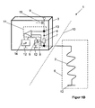
- This heating device 2 comprises a resistance heater 2 and a control device 3.
- This resistance heater 2 is used to heat a surface in a motor vehicle, for example, the seat surface and / or the backrest surface of a seat or a steering wheel rim.
- the heating area of this resistance heater 2 is indicated by the broken line 6.
- the resistance heater 2 is connected at its one end to ground 12 or via the control device 3 extending ground supply and is connected to the other side to the control device 3.
- the resistance heater 2 is deposited or removed from the control device 3, which is indicated by the dashed line 10. Due to this remote mounting of the control device 3 from the heating surface to be controlled, there are no marking or positioning problems in the user-guided area, the heating area 6.
- the block diagram of the control device 3 of Figure 1A comprises a current measuring device 11 and an auxiliary resistor 7, which is connected by thermal coupling, indicated by the arrow 8, with a temperature sensor 5 in connection.
- the thermal coupling is achieved by the auxiliary resistor 7, which is present separately to the current measuring device 11, for which it is advantageous that the temperature sensor 5 and the auxiliary resistor 7 are spatially close, that is connected to each other via a common mass 12, as quickly as possible Determine the temperature of the auxiliary resistor 7 with the temperature sensor 5.
- the auxiliary resistor 7 and the resistance heater 2 are supplied via a node 13 with voltage of a supply voltage 9.
- the other side of the auxiliary resistor 7 is connected to the ground 12.
- the temperature sensor 5 is placed on its one side to ground 12, while its other side is connected to a microprocessor 14. At the same time, this microprocessor 14 is connected on the input side to the current measuring device 11.
- the required amount of heat is determined analogous to a temperature-dependent timing, which leads to the desired surface temperature in the heating region 6 of the resistance heater 2.
- the temperature profile of the resistance heater 2 over time when exposed to a certain amount of heat can be determined. Due to external influences and different covers or covers (covering materials of the seat or the steering wheel), the reality deviates strongly from the measured heat. Therefore, by means of the accurate current measurement, the temperature of the resistance heater 2 is read out via the change in the load current 4 caused by the temperature coefficient of the heating conductor used in the resistance heater 2.
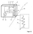
- the block diagram of the control device 3 has a current measuring device 11, which contains an auxiliary resistor 7, which is connected by thermal coupling 8 to a temperature sensor 5. Since no common potential is present in this embodiment, the temperature sensor 5 measures the temperature of the auxiliary resistor 7 indirectly by a spatially close arrangement. The auxiliary resistor 7 and the resistance heater 2 are traversed by the same current. The temperature sensor 5 is grounded 12 on one side while its other side is connected to the microprocessor 14. At the same time, this microprocessor 14 is on the input side with the current measuring device 11 connected. This structure is cheaper, but less fast or dynamic in detecting temperature changes.
- the auxiliary resistor 7 generates a temperature in the control device 3 which rises or falls simultaneously with the temperature of the heating section 6. The temperature is detected by the temperature sensor 5, which is arranged in the control device 3.
- FIG. 1C In the block diagram of Figure 1C is the temperature sensor 5 with the switch 15 via the thermal coupling 8 in connection.
- the switch 15 is, as in all Figures 1A . 1B and 1C illustrated, designed as a MOSFET and therefore includes a turn-on resistor, not shown, which fulfills the function of the auxiliary resistor 7.
- the temperature sensor 5 is grounded 12 on one side while its other side is connected to the microprocessor 14. At the same time, the microprocessor 14 is connected on the input side to the current measuring device 11.
- the heating device 1 as shown in the figures, thus comprising a resistance heater 2 and a control device 3.
- This resistance heater 2 is used to a surface in a motor vehicle, for example, the seat and / or backrest surface of a seat or the steering wheel rim to heat.
- the heating area of this resistance heater 2 is indicated by the broken line 6.
- FIG. 2 is a control diagram of the heating device according to the invention shown, to which in the general part of the description reference has already been made.
- a circuit breaker 15 can be seen, which cyclically activates or deactivates the resistance heater 2 and at the same time the auxiliary resistor 7 via a regulator 16.
- the controller 16 compares the temperature of the temperature sensor 5 with a desired value which is obtained from the heating behavior of the resistance heater 2.
- a maximum permissible value of the resistance heater 2 is defined at the turn-on moment 18 on the assumption that the initially measured temperature of the temperature sensor 5 is comparable to the temperature of the resistance heater 2.
- an offset is added in dependence on a heating level to the previously determined controller parameters.
Landscapes
- Engineering & Computer Science (AREA)
- Aviation & Aerospace Engineering (AREA)
- Transportation (AREA)
- Mechanical Engineering (AREA)
- Physics & Mathematics (AREA)
- General Physics & Mathematics (AREA)
- Automation & Control Theory (AREA)
- Control Of Resistance Heating (AREA)
Applications Claiming Priority (1)
| Application Number | Priority Date | Filing Date | Title |
|---|---|---|---|
| DE102013007243 | 2013-04-26 |
Publications (2)
| Publication Number | Publication Date |
|---|---|
| EP2805869A1 true EP2805869A1 (fr) | 2014-11-26 |
| EP2805869B1 EP2805869B1 (fr) | 2018-07-11 |
Family
ID=50628603
Family Applications (1)
| Application Number | Title | Priority Date | Filing Date |
|---|---|---|---|
| EP14001457.2A Active EP2805869B1 (fr) | 2013-04-26 | 2014-04-23 | Dispositif de chauffage pour des véhicules automobiles, chauffage de siège et chauffage de volant doté d'un tel dispositif de chauffage et procédé de commande de la température d'un dispositif de chauffage pour des véhicules automobiles |
Country Status (1)
| Country | Link |
|---|---|
| EP (1) | EP2805869B1 (fr) |
Cited By (6)
| Publication number | Priority date | Publication date | Assignee | Title |
|---|---|---|---|---|
| EP3202616A1 (fr) * | 2016-02-03 | 2017-08-09 | Sensirion Holding AG | Régulation climatique par module de capteur d'humidité intégré dans un siège |
| CN107651066A (zh) * | 2017-09-25 | 2018-02-02 | 天津永霖科技有限公司 | 一种智能加热坐垫控制方法及控制电路 |
| EP3227161B1 (fr) | 2014-12-04 | 2020-07-08 | Valeo Schalter und Sensoren GmbH | Système de capteur pour un volant de vehicule, volant avec un tel sytème et procédé pour opérer un tel système |
| CN111526608A (zh) * | 2020-04-21 | 2020-08-11 | 天津暖曦科技有限公司 | 一种加热及人体感应共用电路、方向盘及汽车座椅 |
| WO2020192816A1 (fr) * | 2019-03-28 | 2020-10-01 | Gentherm Gmbh | Contrôleur électronique pour un dispositif de chauffage |
| WO2020239159A1 (fr) * | 2019-05-29 | 2020-12-03 | Gentherm Gmbh | Dispositif de détermination de la température d'un système de chauffage à résistance |
Citations (7)
| Publication number | Priority date | Publication date | Assignee | Title |
|---|---|---|---|---|
| GB2093320A (en) * | 1981-02-18 | 1982-08-25 | Micropore International Ltd | An electric cooker |
| AT373116B (de) * | 1976-10-29 | 1983-12-27 | Backer Elektro Vaerme | Vorrichtung zur temperaturbegrenzung bei kanalheizern |
| DE4141224A1 (de) | 1991-12-13 | 1993-06-17 | Bauerhin I G Elektro Tech | Verfahren zur steuerung der heizleistung eines flaechenheizelementes |
| JPH06301427A (ja) * | 1993-04-15 | 1994-10-28 | Mitsubishi Cable Ind Ltd | シートヒータの制御装置 |
| DE10206114C1 (de) | 2002-02-13 | 2003-05-15 | Wet Automotive Systems Ag | Klimatisierungsvorrichtung mit Bedieneinrichtung |
| DE102006034466A1 (de) * | 2006-07-26 | 2008-01-31 | Audi Ag | Kraftfahrzeug |
| US20120049586A1 (en) * | 2009-05-26 | 2012-03-01 | Panasonic Corporation | Planar heating device and seat with same |
-
2014
- 2014-04-23 EP EP14001457.2A patent/EP2805869B1/fr active Active
Patent Citations (7)
| Publication number | Priority date | Publication date | Assignee | Title |
|---|---|---|---|---|
| AT373116B (de) * | 1976-10-29 | 1983-12-27 | Backer Elektro Vaerme | Vorrichtung zur temperaturbegrenzung bei kanalheizern |
| GB2093320A (en) * | 1981-02-18 | 1982-08-25 | Micropore International Ltd | An electric cooker |
| DE4141224A1 (de) | 1991-12-13 | 1993-06-17 | Bauerhin I G Elektro Tech | Verfahren zur steuerung der heizleistung eines flaechenheizelementes |
| JPH06301427A (ja) * | 1993-04-15 | 1994-10-28 | Mitsubishi Cable Ind Ltd | シートヒータの制御装置 |
| DE10206114C1 (de) | 2002-02-13 | 2003-05-15 | Wet Automotive Systems Ag | Klimatisierungsvorrichtung mit Bedieneinrichtung |
| DE102006034466A1 (de) * | 2006-07-26 | 2008-01-31 | Audi Ag | Kraftfahrzeug |
| US20120049586A1 (en) * | 2009-05-26 | 2012-03-01 | Panasonic Corporation | Planar heating device and seat with same |
Cited By (10)
| Publication number | Priority date | Publication date | Assignee | Title |
|---|---|---|---|---|
| EP3227161B1 (fr) | 2014-12-04 | 2020-07-08 | Valeo Schalter und Sensoren GmbH | Système de capteur pour un volant de vehicule, volant avec un tel sytème et procédé pour opérer un tel système |
| EP3202616A1 (fr) * | 2016-02-03 | 2017-08-09 | Sensirion Holding AG | Régulation climatique par module de capteur d'humidité intégré dans un siège |
| WO2017134255A1 (fr) * | 2016-02-03 | 2017-08-10 | Sensirion Ag | Régulation de la climatisation par un module de capteur d'humidité intégré dans un siège |
| US10875429B2 (en) | 2016-02-03 | 2020-12-29 | Sensirion Automotive Solutions Ag | Climate control by in-seat humidity sensor module |
| CN107651066A (zh) * | 2017-09-25 | 2018-02-02 | 天津永霖科技有限公司 | 一种智能加热坐垫控制方法及控制电路 |
| WO2020192816A1 (fr) * | 2019-03-28 | 2020-10-01 | Gentherm Gmbh | Contrôleur électronique pour un dispositif de chauffage |
| WO2020239159A1 (fr) * | 2019-05-29 | 2020-12-03 | Gentherm Gmbh | Dispositif de détermination de la température d'un système de chauffage à résistance |
| CN113950867A (zh) * | 2019-05-29 | 2022-01-18 | 捷温有限责任公司 | 用于确定电阻加热装置的温度的设备 |
| CN111526608A (zh) * | 2020-04-21 | 2020-08-11 | 天津暖曦科技有限公司 | 一种加热及人体感应共用电路、方向盘及汽车座椅 |
| CN111526608B (zh) * | 2020-04-21 | 2022-06-03 | 天津暖曦科技有限公司 | 一种加热及人体感应共用电路、方向盘及汽车座椅 |
Also Published As
| Publication number | Publication date |
|---|---|
| EP2805869B1 (fr) | 2018-07-11 |
Similar Documents
| Publication | Publication Date | Title |
|---|---|---|
| EP2805869B1 (fr) | Dispositif de chauffage pour des véhicules automobiles, chauffage de siège et chauffage de volant doté d'un tel dispositif de chauffage et procédé de commande de la température d'un dispositif de chauffage pour des véhicules automobiles | |
| EP2664905B1 (fr) | Dispositif de mesure de température, appareil électrique doté d'un tel dispositif de mesure de la température et procédé de mesure de la température | |
| DE112016001183T5 (de) | Lenkradgrifferfassungsvorrichtung | |
| DE4434559C2 (de) | Verfahren und Anordnung zum Betrieb eines Füllstandssensors | |
| EP3417672B1 (fr) | Dispositif electrique, en particulier chauffeur electrique, ainsi qu'un dispositif et une methode de controle d'un dispositif electrique | |
| EP3199876B1 (fr) | Procédé et dispositif destinés à influencer un réglage de chauffage | |
| DE102015108888B4 (de) | Überhitzungserkennungsvorrichtung für einen Elektromotor, ausgestattet mit mehreren PTC Thermistoren | |
| EP3508029B1 (fr) | Dispositif de chauffage électrique et procédé de détection de surchauffe d'un tel dispositif de chauffage électrique | |
| EP3566032A1 (fr) | Transmetteur de valeur limite de température | |
| DE112020001843T5 (de) | Thermisches system mit einer temperaturbegrenzungsvorrichtung | |
| EP1384390B1 (fr) | Procede et dispositif de regulation de la temperature d'un radiateur fonctionnant avec un element chauffant presentant un coefficient de temperature positif | |
| DE102014216610A1 (de) | Überwachung einer Spule | |
| DE102012214717A1 (de) | Verfahren und Vorrichtung zur Leistungssteuerung oder Spannungssteuerung eines elektrischen Verbrauchers | |
| WO2021058302A1 (fr) | Procédé et dispositif pour déterminer un élément d'information de température décrivant la température d'un détecteur de température de résistance, onduleur, véhicule et programme informatique | |
| EP1700177B1 (fr) | Ensemble circuit destine a proteger un element chauffant contre la surchauffe, dispositif chauffant et procede pour proteger par fusibles ce dispositif chauffant | |
| DE102014104959B4 (de) | System und Verfahren zum Steuern eines Aktors aus aktiven Materialien | |
| EP1349428B1 (fr) | Corps de chauffe en procédé de commande d'un corps de chauffe en particulier destiné à une voiture | |
| DE112007002958B4 (de) | Vorrichtung und Verfahren zur Bestimmung eines Füllstandes und einer Temperatur eines Fluids | |
| DE2539117C3 (de) | Verfahren und Einrichtung zur Aufladung einer elektrischen Speicherheizung | |
| DE102016120569B4 (de) | Elektrisch einstellbare Temperatursensor-Vorrichtung eines Heizsystems | |
| DE102004018533B4 (de) | Transistorbasierter Temperatursensor | |
| DE102007023644A1 (de) | Heizung, insbesondere für Fahrzeuge, mit zwei Heizgeräten nach dem Prinzip der Master-Slave-Steuerung | |
| EP3211377A1 (fr) | Capteur et procede de chauffage d'un capteur | |
| DE10357771B4 (de) | Steuereinheit und Steuervorrichtung mit der Steuereinheit | |
| DE102016117323B3 (de) | Verfahren zur Konstanthaltung des dem Brennerraum eines mobilen Heizgerätes zugeführten Verbrennungsluft-Massenstroms und nach einem solchen Verfahren arbeitendes Heizgerät |
Legal Events
| Date | Code | Title | Description |
|---|---|---|---|
| PUAI | Public reference made under article 153(3) epc to a published international application that has entered the european phase |
Free format text: ORIGINAL CODE: 0009012 |
|
| 17P | Request for examination filed |
Effective date: 20140423 |
|
| AK | Designated contracting states |
Kind code of ref document: A1 Designated state(s): AL AT BE BG CH CY CZ DE DK EE ES FI FR GB GR HR HU IE IS IT LI LT LU LV MC MK MT NL NO PL PT RO RS SE SI SK SM TR |
|
| AX | Request for extension of the european patent |
Extension state: BA ME |
|
| R17P | Request for examination filed (corrected) |
Effective date: 20150522 |
|
| RBV | Designated contracting states (corrected) |
Designated state(s): AL AT BE BG CH CY CZ DE DK EE ES FI FR GB GR HR HU IE IS IT LI LT LU LV MC MK MT NL NO PL PT RO RS SE SI SK SM TR |
|
| REG | Reference to a national code |
Ref country code: DE Ref legal event code: R079 Ref document number: 502014008764 Country of ref document: DE Free format text: PREVIOUS MAIN CLASS: B62D0001060000 Ipc: G05D0023240000 |
|
| RIC1 | Information provided on ipc code assigned before grant |
Ipc: B60N 2/56 20060101ALI20171228BHEP Ipc: G05D 23/24 20060101AFI20171228BHEP Ipc: H05B 1/02 20060101ALI20171228BHEP |
|
| GRAP | Despatch of communication of intention to grant a patent |
Free format text: ORIGINAL CODE: EPIDOSNIGR1 |
|
| STAA | Information on the status of an ep patent application or granted ep patent |
Free format text: STATUS: GRANT OF PATENT IS INTENDED |
|
| INTG | Intention to grant announced |
Effective date: 20180206 |
|
| GRAS | Grant fee paid |
Free format text: ORIGINAL CODE: EPIDOSNIGR3 |
|
| GRAA | (expected) grant |
Free format text: ORIGINAL CODE: 0009210 |
|
| STAA | Information on the status of an ep patent application or granted ep patent |
Free format text: STATUS: THE PATENT HAS BEEN GRANTED |
|
| AK | Designated contracting states |
Kind code of ref document: B1 Designated state(s): AL AT BE BG CH CY CZ DE DK EE ES FI FR GB GR HR HU IE IS IT LI LT LU LV MC MK MT NL NO PL PT RO RS SE SI SK SM TR |
|
| REG | Reference to a national code |
Ref country code: GB Ref legal event code: FG4D Free format text: NOT ENGLISH |
|
| REG | Reference to a national code |
Ref country code: CH Ref legal event code: EP |
|
| REG | Reference to a national code |
Ref country code: AT Ref legal event code: REF Ref document number: 1017552 Country of ref document: AT Kind code of ref document: T Effective date: 20180715 |
|
| REG | Reference to a national code |
Ref country code: IE Ref legal event code: FG4D Free format text: LANGUAGE OF EP DOCUMENT: GERMAN |
|
| REG | Reference to a national code |
Ref country code: DE Ref legal event code: R096 Ref document number: 502014008764 Country of ref document: DE |
|
| REG | Reference to a national code |
Ref country code: NL Ref legal event code: MP Effective date: 20180711 |
|
| REG | Reference to a national code |
Ref country code: LT Ref legal event code: MG4D |
|
| PG25 | Lapsed in a contracting state [announced via postgrant information from national office to epo] |
Ref country code: NL Free format text: LAPSE BECAUSE OF FAILURE TO SUBMIT A TRANSLATION OF THE DESCRIPTION OR TO PAY THE FEE WITHIN THE PRESCRIBED TIME-LIMIT Effective date: 20180711 |
|
| PG25 | Lapsed in a contracting state [announced via postgrant information from national office to epo] |
Ref country code: NO Free format text: LAPSE BECAUSE OF FAILURE TO SUBMIT A TRANSLATION OF THE DESCRIPTION OR TO PAY THE FEE WITHIN THE PRESCRIBED TIME-LIMIT Effective date: 20181011 Ref country code: GR Free format text: LAPSE BECAUSE OF FAILURE TO SUBMIT A TRANSLATION OF THE DESCRIPTION OR TO PAY THE FEE WITHIN THE PRESCRIBED TIME-LIMIT Effective date: 20181012 Ref country code: BG Free format text: LAPSE BECAUSE OF FAILURE TO SUBMIT A TRANSLATION OF THE DESCRIPTION OR TO PAY THE FEE WITHIN THE PRESCRIBED TIME-LIMIT Effective date: 20181011 Ref country code: PL Free format text: LAPSE BECAUSE OF FAILURE TO SUBMIT A TRANSLATION OF THE DESCRIPTION OR TO PAY THE FEE WITHIN THE PRESCRIBED TIME-LIMIT Effective date: 20180711 Ref country code: SE Free format text: LAPSE BECAUSE OF FAILURE TO SUBMIT A TRANSLATION OF THE DESCRIPTION OR TO PAY THE FEE WITHIN THE PRESCRIBED TIME-LIMIT Effective date: 20180711 Ref country code: LT Free format text: LAPSE BECAUSE OF FAILURE TO SUBMIT A TRANSLATION OF THE DESCRIPTION OR TO PAY THE FEE WITHIN THE PRESCRIBED TIME-LIMIT Effective date: 20180711 Ref country code: FI Free format text: LAPSE BECAUSE OF FAILURE TO SUBMIT A TRANSLATION OF THE DESCRIPTION OR TO PAY THE FEE WITHIN THE PRESCRIBED TIME-LIMIT Effective date: 20180711 Ref country code: RS Free format text: LAPSE BECAUSE OF FAILURE TO SUBMIT A TRANSLATION OF THE DESCRIPTION OR TO PAY THE FEE WITHIN THE PRESCRIBED TIME-LIMIT Effective date: 20180711 Ref country code: IS Free format text: LAPSE BECAUSE OF FAILURE TO SUBMIT A TRANSLATION OF THE DESCRIPTION OR TO PAY THE FEE WITHIN THE PRESCRIBED TIME-LIMIT Effective date: 20181111 |
|
| PG25 | Lapsed in a contracting state [announced via postgrant information from national office to epo] |
Ref country code: AL Free format text: LAPSE BECAUSE OF FAILURE TO SUBMIT A TRANSLATION OF THE DESCRIPTION OR TO PAY THE FEE WITHIN THE PRESCRIBED TIME-LIMIT Effective date: 20180711 Ref country code: ES Free format text: LAPSE BECAUSE OF FAILURE TO SUBMIT A TRANSLATION OF THE DESCRIPTION OR TO PAY THE FEE WITHIN THE PRESCRIBED TIME-LIMIT Effective date: 20180711 Ref country code: LV Free format text: LAPSE BECAUSE OF FAILURE TO SUBMIT A TRANSLATION OF THE DESCRIPTION OR TO PAY THE FEE WITHIN THE PRESCRIBED TIME-LIMIT Effective date: 20180711 Ref country code: HR Free format text: LAPSE BECAUSE OF FAILURE TO SUBMIT A TRANSLATION OF THE DESCRIPTION OR TO PAY THE FEE WITHIN THE PRESCRIBED TIME-LIMIT Effective date: 20180711 |
|
| REG | Reference to a national code |
Ref country code: DE Ref legal event code: R097 Ref document number: 502014008764 Country of ref document: DE |
|
| PG25 | Lapsed in a contracting state [announced via postgrant information from national office to epo] |
Ref country code: EE Free format text: LAPSE BECAUSE OF FAILURE TO SUBMIT A TRANSLATION OF THE DESCRIPTION OR TO PAY THE FEE WITHIN THE PRESCRIBED TIME-LIMIT Effective date: 20180711 Ref country code: RO Free format text: LAPSE BECAUSE OF FAILURE TO SUBMIT A TRANSLATION OF THE DESCRIPTION OR TO PAY THE FEE WITHIN THE PRESCRIBED TIME-LIMIT Effective date: 20180711 Ref country code: CZ Free format text: LAPSE BECAUSE OF FAILURE TO SUBMIT A TRANSLATION OF THE DESCRIPTION OR TO PAY THE FEE WITHIN THE PRESCRIBED TIME-LIMIT Effective date: 20180711 |
|
| PLBE | No opposition filed within time limit |
Free format text: ORIGINAL CODE: 0009261 |
|
| STAA | Information on the status of an ep patent application or granted ep patent |
Free format text: STATUS: NO OPPOSITION FILED WITHIN TIME LIMIT |
|
| PG25 | Lapsed in a contracting state [announced via postgrant information from national office to epo] |
Ref country code: SK Free format text: LAPSE BECAUSE OF FAILURE TO SUBMIT A TRANSLATION OF THE DESCRIPTION OR TO PAY THE FEE WITHIN THE PRESCRIBED TIME-LIMIT Effective date: 20180711 Ref country code: DK Free format text: LAPSE BECAUSE OF FAILURE TO SUBMIT A TRANSLATION OF THE DESCRIPTION OR TO PAY THE FEE WITHIN THE PRESCRIBED TIME-LIMIT Effective date: 20180711 Ref country code: SM Free format text: LAPSE BECAUSE OF FAILURE TO SUBMIT A TRANSLATION OF THE DESCRIPTION OR TO PAY THE FEE WITHIN THE PRESCRIBED TIME-LIMIT Effective date: 20180711 |
|
| 26N | No opposition filed |
Effective date: 20190412 |
|
| PG25 | Lapsed in a contracting state [announced via postgrant information from national office to epo] |
Ref country code: SI Free format text: LAPSE BECAUSE OF FAILURE TO SUBMIT A TRANSLATION OF THE DESCRIPTION OR TO PAY THE FEE WITHIN THE PRESCRIBED TIME-LIMIT Effective date: 20180711 |
|
| REG | Reference to a national code |
Ref country code: CH Ref legal event code: PL |
|
| REG | Reference to a national code |
Ref country code: BE Ref legal event code: MM Effective date: 20190430 |
|
| PG25 | Lapsed in a contracting state [announced via postgrant information from national office to epo] |
Ref country code: MC Free format text: LAPSE BECAUSE OF FAILURE TO SUBMIT A TRANSLATION OF THE DESCRIPTION OR TO PAY THE FEE WITHIN THE PRESCRIBED TIME-LIMIT Effective date: 20180711 Ref country code: LU Free format text: LAPSE BECAUSE OF NON-PAYMENT OF DUE FEES Effective date: 20190423 |
|
| PG25 | Lapsed in a contracting state [announced via postgrant information from national office to epo] |
Ref country code: CH Free format text: LAPSE BECAUSE OF NON-PAYMENT OF DUE FEES Effective date: 20190430 Ref country code: LI Free format text: LAPSE BECAUSE OF NON-PAYMENT OF DUE FEES Effective date: 20190430 |
|
| PG25 | Lapsed in a contracting state [announced via postgrant information from national office to epo] |
Ref country code: BE Free format text: LAPSE BECAUSE OF NON-PAYMENT OF DUE FEES Effective date: 20190430 |
|
| PG25 | Lapsed in a contracting state [announced via postgrant information from national office to epo] |
Ref country code: TR Free format text: LAPSE BECAUSE OF FAILURE TO SUBMIT A TRANSLATION OF THE DESCRIPTION OR TO PAY THE FEE WITHIN THE PRESCRIBED TIME-LIMIT Effective date: 20180711 |
|
| PG25 | Lapsed in a contracting state [announced via postgrant information from national office to epo] |
Ref country code: IE Free format text: LAPSE BECAUSE OF NON-PAYMENT OF DUE FEES Effective date: 20190423 |
|
| PG25 | Lapsed in a contracting state [announced via postgrant information from national office to epo] |
Ref country code: PT Free format text: LAPSE BECAUSE OF FAILURE TO SUBMIT A TRANSLATION OF THE DESCRIPTION OR TO PAY THE FEE WITHIN THE PRESCRIBED TIME-LIMIT Effective date: 20181111 |
|
| REG | Reference to a national code |
Ref country code: AT Ref legal event code: MM01 Ref document number: 1017552 Country of ref document: AT Kind code of ref document: T Effective date: 20190423 |
|
| PG25 | Lapsed in a contracting state [announced via postgrant information from national office to epo] |
Ref country code: AT Free format text: LAPSE BECAUSE OF NON-PAYMENT OF DUE FEES Effective date: 20190423 |
|
| PG25 | Lapsed in a contracting state [announced via postgrant information from national office to epo] |
Ref country code: CY Free format text: LAPSE BECAUSE OF FAILURE TO SUBMIT A TRANSLATION OF THE DESCRIPTION OR TO PAY THE FEE WITHIN THE PRESCRIBED TIME-LIMIT Effective date: 20180711 |
|
| PG25 | Lapsed in a contracting state [announced via postgrant information from national office to epo] |
Ref country code: MT Free format text: LAPSE BECAUSE OF FAILURE TO SUBMIT A TRANSLATION OF THE DESCRIPTION OR TO PAY THE FEE WITHIN THE PRESCRIBED TIME-LIMIT Effective date: 20180711 Ref country code: HU Free format text: LAPSE BECAUSE OF FAILURE TO SUBMIT A TRANSLATION OF THE DESCRIPTION OR TO PAY THE FEE WITHIN THE PRESCRIBED TIME-LIMIT; INVALID AB INITIO Effective date: 20140423 |
|
| PG25 | Lapsed in a contracting state [announced via postgrant information from national office to epo] |
Ref country code: MK Free format text: LAPSE BECAUSE OF FAILURE TO SUBMIT A TRANSLATION OF THE DESCRIPTION OR TO PAY THE FEE WITHIN THE PRESCRIBED TIME-LIMIT Effective date: 20180711 |
|
| PGFP | Annual fee paid to national office [announced via postgrant information from national office to epo] |
Ref country code: GB Payment date: 20240423 Year of fee payment: 11 |
|
| PGFP | Annual fee paid to national office [announced via postgrant information from national office to epo] |
Ref country code: DE Payment date: 20240429 Year of fee payment: 11 |
|
| PGFP | Annual fee paid to national office [announced via postgrant information from national office to epo] |
Ref country code: IT Payment date: 20240423 Year of fee payment: 11 Ref country code: FR Payment date: 20240430 Year of fee payment: 11 |