EP2805869A1 - Heating device for motor vehicles, seat heater and steering wheel heater with such a heating device and method for controlling the temperature of a heating device for motor vehicles - Google Patents
Heating device for motor vehicles, seat heater and steering wheel heater with such a heating device and method for controlling the temperature of a heating device for motor vehicles Download PDFInfo
- Publication number
- EP2805869A1 EP2805869A1 EP14001457.2A EP14001457A EP2805869A1 EP 2805869 A1 EP2805869 A1 EP 2805869A1 EP 14001457 A EP14001457 A EP 14001457A EP 2805869 A1 EP2805869 A1 EP 2805869A1
- Authority
- EP
- European Patent Office
- Prior art keywords
- heating
- resistance heater
- temperature
- control device
- resistance
- Prior art date
- Legal status (The legal status is an assumption and is not a legal conclusion. Google has not performed a legal analysis and makes no representation as to the accuracy of the status listed.)
- Granted
Links
- 238000010438 heat treatment Methods 0.000 title claims abstract description 157
- 238000000034 method Methods 0.000 title claims abstract description 20
- 239000004020 conductor Substances 0.000 claims description 17
- 238000005259 measurement Methods 0.000 claims description 13
- 230000008859 change Effects 0.000 claims description 7
- 238000006243 chemical reaction Methods 0.000 claims description 2
- 230000002123 temporal effect Effects 0.000 claims description 2
- 238000010586 diagram Methods 0.000 description 12
- 230000001419 dependent effect Effects 0.000 description 7
- 230000008878 coupling Effects 0.000 description 4
- 238000010168 coupling process Methods 0.000 description 4
- 238000005859 coupling reaction Methods 0.000 description 4
- 230000001276 controlling effect Effects 0.000 description 3
- 230000008901 benefit Effects 0.000 description 2
- 238000001514 detection method Methods 0.000 description 2
- 230000000694 effects Effects 0.000 description 2
- 239000000463 material Substances 0.000 description 2
- 238000012546 transfer Methods 0.000 description 2
- 230000003213 activating effect Effects 0.000 description 1
- 230000004913 activation Effects 0.000 description 1
- 238000004378 air conditioning Methods 0.000 description 1
- 238000013459 approach Methods 0.000 description 1
- 230000008030 elimination Effects 0.000 description 1
- 238000003379 elimination reaction Methods 0.000 description 1
- 238000005516 engineering process Methods 0.000 description 1
- 230000007613 environmental effect Effects 0.000 description 1
- 238000009434 installation Methods 0.000 description 1
- 238000009413 insulation Methods 0.000 description 1
- 230000007774 longterm Effects 0.000 description 1
- 238000004519 manufacturing process Methods 0.000 description 1
- 238000000691 measurement method Methods 0.000 description 1
- 238000013021 overheating Methods 0.000 description 1
- 230000009467 reduction Effects 0.000 description 1
- 230000001105 regulatory effect Effects 0.000 description 1
Images


Classifications
-
- B—PERFORMING OPERATIONS; TRANSPORTING
- B60—VEHICLES IN GENERAL
- B60N—SEATS SPECIALLY ADAPTED FOR VEHICLES; VEHICLE PASSENGER ACCOMMODATION NOT OTHERWISE PROVIDED FOR
- B60N2/00—Seats specially adapted for vehicles; Arrangement or mounting of seats in vehicles
- B60N2/56—Heating or ventilating devices
- B60N2/5678—Heating or ventilating devices characterised by electrical systems
- B60N2/5685—Resistance
-
- G—PHYSICS
- G05—CONTROLLING; REGULATING
- G05D—SYSTEMS FOR CONTROLLING OR REGULATING NON-ELECTRIC VARIABLES
- G05D23/00—Control of temperature
- G05D23/19—Control of temperature characterised by the use of electric means
- G05D23/20—Control of temperature characterised by the use of electric means with sensing elements having variation of electric or magnetic properties with change of temperature
- G05D23/24—Control of temperature characterised by the use of electric means with sensing elements having variation of electric or magnetic properties with change of temperature the sensing element having a resistance varying with temperature, e.g. a thermistor
-
- H—ELECTRICITY
- H05—ELECTRIC TECHNIQUES NOT OTHERWISE PROVIDED FOR
- H05B—ELECTRIC HEATING; ELECTRIC LIGHT SOURCES NOT OTHERWISE PROVIDED FOR; CIRCUIT ARRANGEMENTS FOR ELECTRIC LIGHT SOURCES, IN GENERAL
- H05B1/00—Details of electric heating devices
- H05B1/02—Automatic switching arrangements specially adapted to apparatus ; Control of heating devices
- H05B1/0227—Applications
- H05B1/023—Industrial applications
- H05B1/0236—Industrial applications for vehicles
Definitions
- the present invention relates to a heating device according to the preamble of claim 1, a seat heating and a steering wheel heating with such a heater and a method for controlling the temperature of at least one heat conductor comprehensive electrical resistance heating for motor vehicles according to the preamble of claim.
- the DE 4141224 A1 describes a method for controlling the heating power of a surface heating element, in particular a motor vehicle seat heater, initially the desired temperature of the surface heating element specified as a setpoint and then the actual value in the form of a temperature-dependent timing of a heating energy source is brought to the temperature setpoint.
- the seat in the occupied state is considered as a closed system, on which no disturbances act.
- a target temperature on the seat surface of a seat cover can be set very precisely by means of a controller.
- This approach requires a precise knowledge of the thermal transfer resistance and the thermal capacity between resistance heating and seat surface.
- This type of electronics has shrunk so much in size that it is housed in the position of the temperature sensor. This eliminates an external temperature sensor. The influence of persons of different weights or the influence of partial or total covers of the surface to be heated is not recorded with this system and thus not taken into account.
- the control technology Disadvantages of the more massive and thereby slower temperature sensor have been compensated by timing functions.
- the DE 10206114 C1 describes an air conditioning device having, among other things, a heating device.
- This heating device also has a control device which is electrically connected to an operating device. It also communicates with a temperature sensor.
- the temperature sensor is preferably arranged in the vicinity of the heating element.
- the control device is connected to the heating element.
- the present invention has for its object to overcome the disadvantages of the prior art, and in particular to provide such an arrangement and a corresponding method in which a temperature sensor (NTC) can be omitted in the heating element, thus producing a simple and inexpensive controllable heater , Furthermore, the temperature sensor from a noticeable Area of a user-touchable surface in which the heater is arranged to be removed in order to eliminate the problem of the sign or the haptic.
- NTC temperature sensor
- the heating device is intended for motor vehicles, preferably for heating a motor vehicle seat (seat and / or backrest) or a steering wheel, and comprises an electrical resistance heater with at least one heating conductor and a control device associated with this resistance heater and a temperature sensor.
- the heating conductor has a defined temperature coefficient.
- the controller is located away from the resistance heater outside of its heating area.
- the control device has an auxiliary resistor, which is thus likewise arranged away from the resistance heater outside its heating region and thus is not influenced by the heat emitted directly by the resistance heater.
- the auxiliary resistor is applied to a voltage or is flowed through by a current, wherein this voltage or this current is proportional to the voltage applied to the resistance heating or the current flowing through the resistance heating current.
- the temperature sensor is arranged within the control device so that it is thermally coupled to the auxiliary resistor.
- the resistance heater is consequently supplied as a function of a desired value via the control device with heating current and the setpoint temperature of the resistance heating is controlled on the basis of the detection of actual values.
- the heating device comprises the temperature sensor, which detects a temperature in the control device.
- the control device is arranged away from the resistance heating outside its heating region and has the auxiliary resistance which is supplied with the heating current of the resistance heater or the voltage applied to the resistance heating voltage. Characteristics are stored in the control device which generate the heat from the heating as a function of the heating current Heat correlate to the heat generated by the auxiliary resistance in the control device for detecting the actual values.
- the method according to the invention serves to control the temperature of an electrical resistance heater for motor vehicles comprising at least one heating conductor by means of a control device and a temperature sensor.
- the temperature of the thermally coupled with an auxiliary resistor temperature sensor is used to adjust the voltage applied to the resistance heating or the current flowing through the resistance heating current.
- the auxiliary resistance in the control device serves as a heating model for the resistance heating, to which the auxiliary resistance is operated with a voltage proportional to the voltage applied to the resistance heating or with a current which is proportional to the current flowing through the resistance heating current.
- An advantage of this invention is also to be seen in the fact that the remote installation of the control device from the surface to be heated and thus controlled does not lead to any problems of marking or positioning in the user-related area, for example steering wheel or vehicle seat. Also, this provides improved control accuracy for partial coverage of the user-led area.
- the at least one temperature sensor such as an NTC, and the associated positioning, a lighter, faster and thus more cost-effective temperature adjustment is possible; Also, the reliability is increased by the elimination of the temperature sensor.
- control device has a voltage and / or current measuring device associated with the resistance heater.
- control device has a microprocessor in which characteristic curves are stored, which measure the temperature measured via the temperature sensor to the voltage applied to the resistance heater and / or to the current supplied to the resistance heater and thus to the temperature generated by the heater assign. These characteristics are specific to the heater under different environmental conditions, such as ambient temperature and humidity, for example, are determined and stored so that the control device can access these characteristics in order to correlate certain values which it determines during operation of the heating device during operation.
- the characteristics are tuned to the temporal behavior of the temperature changes of the resistance heating due to changes in the voltage applied to the resistance heating voltage and / or due to changes in the resistance heating current supplied.
- a temperature change of the resistance heating is additionally used by means of a measurement of the voltage applied to the resistance heating and a measurement of the current flowing through the resistance heating and a conversion of these measured values taking into account the temperature coefficient of the heating conductor of the resistance heating for controlling the resistance heating.
- the resistance heating can be adjusted by means stored in the control device characteristics and taking into account the temperature coefficient of the heating element.
- the resistance heating is set by means of characteristic curves stored in the control device which associate the temperature measured via the temperature sensor with the voltage applied to the resistance heating.
- the resistance heating is adjusted by means of characteristic curves stored in the control device, which assign the temperature measured via the temperature sensor to the current flowing through the resistance heating current.
- an observer in control engineering is a system that reconstructs unmeasurable quantities from known input and output variables of an observed system.
- the observed reference system is called Model used; it contains a controller that tracks the measurable state variables.
- An observer can only be designed if the reference system is observable over the existing measurands.
- the known from the prior art control electronics, which is integrated in the heating mat, is a more precise current measurement with an accuracy of ⁇ 1%, (usually> ⁇ 10% accuracy for overload circuits) and an auxiliary resistance that is thermal with the temperature sensor coupled, extended.
- the required amount of heat is determined analogously to a temperature-dependent timing, which leads to the desired surface temperature. Also, knowing the area to be heated specifically and thus the controlled system, the temperature profile of the heating wire can be determined over time when this amount of heat is applied. Due to external influences and different references, the reality deviates strongly from the measured heat. Therefore, by means of the accurate current measurement, the temperature of the heating conductor is read out via the change in the load current caused by the temperature coefficient of the heating conductor used.
- the load current is equated with the starting temperature in the starting case and a maximum heating of the heating conductor is specified with permissible current drop. This ensures that there is no overheating due to a cover of the heater.
- the temperature of the heating element is recorded over time, making the heating model plausible. Deviations and thus influences of different loads (loads) and covers (eg seat or steering wheel covers) or even heating conductor failures are thus recorded and corrected.
- a method for operating the heating device according to the invention is described (see also FIG. 2 ).
- a supply voltage is applied simultaneously to an auxiliary resistor in the control device and to a heating conductor in the resistance heater, wherein the resistance thereof changes as a function of the temperature of the resistance heating.
- a continuous determination of the at least one temperature of the control device and a continuous detection of at least one load current and at least one load voltage of the resistance heating is carried out.
- the starting states of load current, load voltage and starting temperature of the control device are stored.
- the intended method assumes that the starting temperature of the control device is identical to the starting temperature of the resistance heater, since resistance heating and control device are arranged in the same environment.
- the operating history of the resistance heating is stored in the form of amount of heat in the control device.
- a characteristic curve is stored in the control device which sets the time profile of the temperature of the control device, heated by the auxiliary resistance, in relation to the time profile of the temperature of the heating device, heated by the load resistance, in the resistance heater.
- the resistance of the resistance heater (heating conductor) is continuously measured through at least one load current and at least one load voltage.
- the resistance of the resistance heater changes according to the material-dependent temperature coefficient as a function of the temperature of the resistance heater.
- the temperature of the resistance heating can thus be determined continuously.
- the advantage of using the relative change in resistance is that the system is independent of long term drift of the measurement technique, manufacturing tolerances and changes in resistance heating when installed.
- the temperature of the resistance heating based on the known heating behavior of the resistance heating and a known starting temperature, can be determined from the amount of heat supplied.
- a desired temperature of the control device is defined, which is kept constant by a control loop.
- the power supplied to the resistance heating is limited.
- the power is limited so that the temperature of the resistance heating, which is determined by voltage and current measurement of the resistance heating, remains constant.
- a limitation of the temperature of the resistance heating is achieved.
- the heating of the resistance heating is also constantly with the known heating behavior of the resistance heating at a given starting temperature compared. In case of deviations, excessive heating of the resistance heating is avoided by reducing the heating power.
- the heating power limitation is achieved by cyclically activating and deactivating a circuit breaker, which applies voltage to the resistance heater and at the same time to the auxiliary resistor.
- An activation time can be between 0% to 100% of the cycle (PWM).
- PWM is the so-called pulse width modulation.
- PWM is a type of modulation in which a technical quantity, such as an electric current, alternates between two values.
- the duty cycle of a pulse is modulated.
- the duty cycle is a dimensionless ratio, with a value of 0 to 1 or 0 to 100%.
- the temperature of the resistance heater transfers from the heating mat to the reference surface and thus gives the reference surface temperature. In this case, the resistance of the resistance heater changes depending on its contact state. Namely, an occupant touching the reference surface removes heat energy from the corresponding surface, causing repercussions on the temperature of the resistance heater. This resistance, the resistance heating is detected by a continuous current and voltage measurement.
- the heating device according to the invention and the inventive method are used in a seat heater or a steering wheel heating.
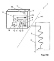
- This heating device 2 comprises a resistance heater 2 and a control device 3.
- This resistance heater 2 is used to heat a surface in a motor vehicle, for example, the seat surface and / or the backrest surface of a seat or a steering wheel rim.
- the heating area of this resistance heater 2 is indicated by the broken line 6.
- the resistance heater 2 is connected at its one end to ground 12 or via the control device 3 extending ground supply and is connected to the other side to the control device 3.
- the resistance heater 2 is deposited or removed from the control device 3, which is indicated by the dashed line 10. Due to this remote mounting of the control device 3 from the heating surface to be controlled, there are no marking or positioning problems in the user-guided area, the heating area 6.
- the block diagram of the control device 3 of Figure 1A comprises a current measuring device 11 and an auxiliary resistor 7, which is connected by thermal coupling, indicated by the arrow 8, with a temperature sensor 5 in connection.
- the thermal coupling is achieved by the auxiliary resistor 7, which is present separately to the current measuring device 11, for which it is advantageous that the temperature sensor 5 and the auxiliary resistor 7 are spatially close, that is connected to each other via a common mass 12, as quickly as possible Determine the temperature of the auxiliary resistor 7 with the temperature sensor 5.
- the auxiliary resistor 7 and the resistance heater 2 are supplied via a node 13 with voltage of a supply voltage 9.
- the other side of the auxiliary resistor 7 is connected to the ground 12.
- the temperature sensor 5 is placed on its one side to ground 12, while its other side is connected to a microprocessor 14. At the same time, this microprocessor 14 is connected on the input side to the current measuring device 11.
- the required amount of heat is determined analogous to a temperature-dependent timing, which leads to the desired surface temperature in the heating region 6 of the resistance heater 2.
- the temperature profile of the resistance heater 2 over time when exposed to a certain amount of heat can be determined. Due to external influences and different covers or covers (covering materials of the seat or the steering wheel), the reality deviates strongly from the measured heat. Therefore, by means of the accurate current measurement, the temperature of the resistance heater 2 is read out via the change in the load current 4 caused by the temperature coefficient of the heating conductor used in the resistance heater 2.
- the block diagram of the control device 3 has a current measuring device 11, which contains an auxiliary resistor 7, which is connected by thermal coupling 8 to a temperature sensor 5. Since no common potential is present in this embodiment, the temperature sensor 5 measures the temperature of the auxiliary resistor 7 indirectly by a spatially close arrangement. The auxiliary resistor 7 and the resistance heater 2 are traversed by the same current. The temperature sensor 5 is grounded 12 on one side while its other side is connected to the microprocessor 14. At the same time, this microprocessor 14 is on the input side with the current measuring device 11 connected. This structure is cheaper, but less fast or dynamic in detecting temperature changes.
- the auxiliary resistor 7 generates a temperature in the control device 3 which rises or falls simultaneously with the temperature of the heating section 6. The temperature is detected by the temperature sensor 5, which is arranged in the control device 3.
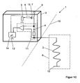
- FIG. 1C In the block diagram of Figure 1C is the temperature sensor 5 with the switch 15 via the thermal coupling 8 in connection.
- the switch 15 is, as in all Figures 1A . 1B and 1C illustrated, designed as a MOSFET and therefore includes a turn-on resistor, not shown, which fulfills the function of the auxiliary resistor 7.
- the temperature sensor 5 is grounded 12 on one side while its other side is connected to the microprocessor 14. At the same time, the microprocessor 14 is connected on the input side to the current measuring device 11.
- the heating device 1 as shown in the figures, thus comprising a resistance heater 2 and a control device 3.
- This resistance heater 2 is used to a surface in a motor vehicle, for example, the seat and / or backrest surface of a seat or the steering wheel rim to heat.
- the heating area of this resistance heater 2 is indicated by the broken line 6.
- FIG. 2 is a control diagram of the heating device according to the invention shown, to which in the general part of the description reference has already been made.
- a circuit breaker 15 can be seen, which cyclically activates or deactivates the resistance heater 2 and at the same time the auxiliary resistor 7 via a regulator 16.
- the controller 16 compares the temperature of the temperature sensor 5 with a desired value which is obtained from the heating behavior of the resistance heater 2.
- a maximum permissible value of the resistance heater 2 is defined at the turn-on moment 18 on the assumption that the initially measured temperature of the temperature sensor 5 is comparable to the temperature of the resistance heater 2.
- an offset is added in dependence on a heating level to the previously determined controller parameters.
Landscapes
- Engineering & Computer Science (AREA)
- Physics & Mathematics (AREA)
- General Physics & Mathematics (AREA)
- Automation & Control Theory (AREA)
- Aviation & Aerospace Engineering (AREA)
- Transportation (AREA)
- Mechanical Engineering (AREA)
- Control Of Resistance Heating (AREA)
Abstract
Die Erfindung betrifft eine Heizeinrichtung für Kraftfahrzeuge mit mindestens einem eine elektrische Widerstandsheizung bildenden Heizleiter, der einen definierten Temperaturkoeffizienten aufweist, mit einer dieser Widerstandsheizung zugeordneten Steuereinrichtung und mit einem Temperatursensor sowie ein Verfahren zur Steuerung der Temperatur einer solchen Widerstandsheizung. Die Steuereinrichtung ist entfernt von der Widerstandsheizung außerhalb deren Heizbereichs angeordnet und weist einen Hilfswiderstand auf, der an einer Spannung anliegt oder durch den ein Strom fließt, die bzw. der proportional zu der an der Widerstandsheizung anliegenden Spannung bzw. dem durch die Widerstandsheizung fließenden Strom ist. Der Temperatursensor ist innerhalb der Steuereinrichtung so angeordnet, dass er thermisch mit dem Hilfswiderstand gekoppelt ist. Heizeinrichtung und Verfahren sind insbesondere zum Einsatz für Fahrzeugsitze oder Fahrzeuglenkräder geeignet.The invention relates to a heating device for motor vehicles with at least one heating element forming an electrical resistance heating, which has a defined temperature coefficient, with a control device associated with this resistance heating and with a temperature sensor and a method for controlling the temperature of such resistance heating. The control device is arranged away from the resistance heating outside its heating region and has an auxiliary resistance which is applied to a voltage or through which a current flows which is proportional to the voltage applied to the resistance heating or the current flowing through the resistance heating current , The temperature sensor is arranged within the control device so that it is thermally coupled to the auxiliary resistor. Heating device and method are particularly suitable for use for vehicle seats or vehicle steering wheels.
Description
Die vorliegende Erfindung betrifft eine Heizeinrichtung gemäß dem Oberbegriff des Anspruchs 1, eine Sitzheizung sowie eine Lenkradheizung mit einer solchen Heizeinrichtung und ein Verfahren zur Steuerung der Temperatur einer mindestens einen Heizleiter umfassenden elektrischen Widerstandsheizung für Kraftfahrzeuge gemäß dem Oberbegriff des Anspruchs 7.The present invention relates to a heating device according to the preamble of
Es ist Stand der Technik für Sitzheizungs- oder Lenkradheizungsregelungen, einen Temperatursensor in die Heizmatte zu integrieren und über einen Soll-Istwert Vergleich die Oberflächentemperatur der Heizmatte zu regeln.It is state of the art for seat heating or steering wheel heating controls to integrate a temperature sensor in the heating mat and to regulate the surface temperature of the heating mat via a nominal-actual value comparison.
Die
Daher kann unter Kenntnis der Starttemperatur sehr genau mittels einer Steuerung eine Solltemperatur an der Sitzoberfläche eines Sitzbezugs eingestellt werden. Dieser Ansatz bedarf einer genauen Kenntnis des wärmetechnischen Übergangswiderstands und der thermischen Kapazität zwischen Widerstandsheizung und Sitzoberfläche. Diese Art der Elektronik ist so stark in ihrer Baugröße geschrumpft, dass sie an der Position des Temperatursensors untergebracht ist. Dadurch entfällt ein externer Temperatursensor. Der Einfluss unterschiedlich schwerer Personen oder der Einfluss von Teil- oder Ganzabdeckungen der zu beheizenden Oberfläche wird mit diesem System nicht erfasst und damit nicht berücksichtigt. Die regelungstechnischen Nachteile des massigeren und dadurch trägeren Temperatursensors sind durch Zeitsteuerungsfunktionen kompensiert worden.Therefore, with knowledge of the starting temperature, a target temperature on the seat surface of a seat cover can be set very precisely by means of a controller. This approach requires a precise knowledge of the thermal transfer resistance and the thermal capacity between resistance heating and seat surface. This type of electronics has shrunk so much in size that it is housed in the position of the temperature sensor. This eliminates an external temperature sensor. The influence of persons of different weights or the influence of partial or total covers of the surface to be heated is not recorded with this system and thus not taken into account. The control technology Disadvantages of the more massive and thereby slower temperature sensor have been compensated by timing functions.
Die
Auch sind Systeme bekannt, die zur Regelung der Oberflächentemperatur den Temperaturkoeffizienten des Heizleiters nutzen. Man hat bereits versucht, auf eine konstante Heizdrahttemperatur zu regeln; dabei ist das Heizmedium als flächiger Temperatursensor genutzt worden. Dadurch sind zumindest ähnlich zur Regelung mit einem diskreten Temperatursensor auch mit Einschränkungen Rückwirkungen von den unterschiedlichen Regelstrecken und Lasten erfasst worden. Auch führt eine Vollabdeckung der Heizung nicht zu extremen Temperaturen, da die Heizleitertemperatur direkt geregelt wird. Jedoch ist auch bei diesen Maßnahmen das Problem der Teilabdeckung, mittels einer vermittelnden Messung über die ganze Heizfläche, nicht gelöst. Der Heizleiter funktioniert wegen seines geringen Temperaturkoeffizienten nur unzureichend als Temperatursensor.Systems are also known which use the temperature coefficient of the heating conductor to control the surface temperature. One has already tried to control to a constant heating wire temperature; while the heating medium has been used as a surface temperature sensor. As a result, at least similar to the control with a discrete temperature sensor, repercussions from the different controlled systems and loads have also been detected with restrictions. Also, a full coverage of the heater does not lead to extreme temperatures, as the Heizleitertemperatur is controlled directly. However, even with these measures, the problem of partial coverage, by means of a mediating measurement over the entire heating surface, not solved. Due to its low temperature coefficient, the heating conductor does not function adequately as a temperature sensor.
Auch sind Systeme, die eine Kombination einer NTC-Regelung mit einer temperaturabhängigen Zeitsteuerung aufweisen, bekannt. Bei dieser Art von Regelung ist die Steuerelektronik selbst soweit geschrumpft, dass diese direkt an der Position des Temperatursensors untergebracht werden kann. Dadurch ist ein externer Temperatursensor entfallen. Die regelungstechnischen Nachteile des nun massigeren und dadurch trägeren Systems sind durch Zeitsteuerungsfunktionen kompensiert worden.Also, systems having a combination of NTC control with temperature-dependent timing are known. In this type of regulation, the control electronics itself shrunk so far that they can be accommodated directly at the position of the temperature sensor. This eliminates an external temperature sensor. The regulatory disadvantages of the now massive and thus slower system have been compensated by timing functions.
Der vorliegenden Erfindung liegt die Aufgabe zugrunde, die Nachteile des Stands der Technik zu beseitigen, und insbesondere eine solche Anordnung sowie ein entsprechendes Verfahren zu schaffen, bei dem ein Temperatursensor (NTC) im Heizelement entfallen kann, um somit eine einfache und kostengünstige regelbare Heizeinrichtung herzustellen. Weiterhin soll der Temperatursensor aus einem spürbaren Bereich einer benutzerberührbaren Fläche, in der die Heizeinrichtung angeordnet ist, entfernt werden, um die Problematik der Abzeichnung bzw. der Haptik zu beseitigen.The present invention has for its object to overcome the disadvantages of the prior art, and in particular to provide such an arrangement and a corresponding method in which a temperature sensor (NTC) can be omitted in the heating element, thus producing a simple and inexpensive controllable heater , Furthermore, the temperature sensor from a noticeable Area of a user-touchable surface in which the heater is arranged to be removed in order to eliminate the problem of the sign or the haptic.
Gelöst wird diese Aufgabe durch eine Heizeinrichtung, mit den Merkmalen des Patentanspruchs 1, durch eine Sitzheizung nach Anspruch 5, durch eine Lenkradheizung nach Anspruch 6 sowie durch ein Verfahren gemäß Anspruch 7. Vorteilhafte Ausgestaltungen ergeben sich aus den Unteransprüchen.This object is achieved by a heating device, with the features of
Die erfindungsgemäße Heizeinrichtung ist für Kraftfahrzeuge, vorzugsweise zum Beheizen eines Kraftfahrzeugsitzes (Sitzfläche und/oder Rückenlehne) oder eines Lenkrads, vorgesehen und umfasst eine elektrische Widerstandsheizung mit mindestens einem Heizleiter und eine dieser Widerstandsheizung zugeordnete Steuereinrichtung sowie einen Temperatursensor. Der Heizleiter besitzt einen definierten Temperaturkoeffizienten. Die Steuereinrichtung ist entfernt von der Widerstandsheizung außerhalb deren Heizbereichs angeordnet. Die Steuereinrichtung weist einen Hilfswiderstand auf, der somit ebenfalls entfernt von der Widerstandsheizung außerhalb deren Heizbereichs angeordnet ist und somit nicht durch die direkt von der Widerstandsheizung abgegebene Wärme beeinflusst wird. Der Hilfswiderstand liegt an einer Spannung an oder wird durch einen Strom durchflossen, wobei diese Spannung bzw. dieser Strom proportional zu der an der Widerstandsheizung anliegenden Spannung bzw. dem durch die Widerstandsheizung fließenden Strom ist. Der Temperatursensor ist innerhalb der Steuereinrichtung so angeordnet, dass er thermisch mit dem Hilfswiderstand gekoppelt ist.The heating device according to the invention is intended for motor vehicles, preferably for heating a motor vehicle seat (seat and / or backrest) or a steering wheel, and comprises an electrical resistance heater with at least one heating conductor and a control device associated with this resistance heater and a temperature sensor. The heating conductor has a defined temperature coefficient. The controller is located away from the resistance heater outside of its heating area. The control device has an auxiliary resistor, which is thus likewise arranged away from the resistance heater outside its heating region and thus is not influenced by the heat emitted directly by the resistance heater. The auxiliary resistor is applied to a voltage or is flowed through by a current, wherein this voltage or this current is proportional to the voltage applied to the resistance heating or the current flowing through the resistance heating current. The temperature sensor is arranged within the control device so that it is thermally coupled to the auxiliary resistor.
Die Widerstandsheizung wird folglich in Abhängigkeit eines Sollwerts über die Steuereinrichtung mit Heizstrom versorgt und die Solltemperatur der Widerstandsheizung wird aufgrund der Erfassung von Istwerten geregelt. Weiterhin umfasst die Heizeinrichtung den Temperatursensor, der eine Temperatur in der Steuereinrichtung erfasst. Die Steuereinrichtung ist entfernt von der Widerstandsheizung außerhalb deren Heizbereichs angeordnet und weist den Hilfswiderstand auf, der mit dem Heizstrom der Widerstandsheizung oder der an der Widerstandsheizung anliegenden Spannung versorgt wird. In der Steuereinrichtung sind Kennlinien gespeichert, die die von der Widerstandsheizung in Abhängigkeit des Heizstroms erzeugte Wärme zu der durch den Hilfswiderstand erzeugten Wärme in der Steuereinrichtung zur Erfassung der Istwerte korrelieren.The resistance heater is consequently supplied as a function of a desired value via the control device with heating current and the setpoint temperature of the resistance heating is controlled on the basis of the detection of actual values. Furthermore, the heating device comprises the temperature sensor, which detects a temperature in the control device. The control device is arranged away from the resistance heating outside its heating region and has the auxiliary resistance which is supplied with the heating current of the resistance heater or the voltage applied to the resistance heating voltage. Characteristics are stored in the control device which generate the heat from the heating as a function of the heating current Heat correlate to the heat generated by the auxiliary resistance in the control device for detecting the actual values.
Das erfindungsgemäße Verfahren dient zur Steuerung der Temperatur einer mindestens einen Heizleiter umfassenden elektrischen Widerstandsheizung für Kraftfahrzeuge mittels einer Steuereinrichtung und eines Temperatursensors. Verfahrensgemäß wird die Temperatur des thermisch mit einem Hilfswiderstand gekoppelten Temperatursensors dazu herangezogen, um die an der Widerstandsheizung anliegende Spannung oder den durch die Widerstandsheizung fließenden Strom einzustellen. Hierbei dient der Hilfswiderstand in der Steuereinrichtung als Aufheizmodell für die Widerstandsheizung, wozu der Hilfswiderstand mit einer Spannung proportional zu der an der Widerstandsheizung anliegenden Spannung oder mit einem Strom, der zu dem durch die Widerstandsheizung fließenden Strom proportional ist, betrieben wird.The method according to the invention serves to control the temperature of an electrical resistance heater for motor vehicles comprising at least one heating conductor by means of a control device and a temperature sensor. According to the method, the temperature of the thermally coupled with an auxiliary resistor temperature sensor is used to adjust the voltage applied to the resistance heating or the current flowing through the resistance heating current. Here, the auxiliary resistance in the control device serves as a heating model for the resistance heating, to which the auxiliary resistance is operated with a voltage proportional to the voltage applied to the resistance heating or with a current which is proportional to the current flowing through the resistance heating current.
Ein Vorteil dieser Erfindung ist auch darin zu sehen, dass es durch die abgesetzte bzw. entfernte Montage der Steuereinrichtung von der zu beheizenden und damit zu regelnden Oberfläche zu keinen Abzeichnungs- oder Positionierungsproblemen im benutzerberührten Bereich, beispielsweise Lenkrad oder Fahrzeugsitz, kommt. Auch ist dadurch eine verbesserte Regelgenauigkeit bei Teilabdeckung der benutzerberührten Fläche gegeben. Durch den Wegfall des mindestens einen Temperatursensors, beispielsweise eines NTC, und der damit verbundenen Positionierung, ist eine leichtere, schnellere und damit kostengünstigere Temperaturabstimmung möglich; auch wird die Funktionssicherheit durch den Wegfall des Temperatursensors erhöht.An advantage of this invention is also to be seen in the fact that the remote installation of the control device from the surface to be heated and thus controlled does not lead to any problems of marking or positioning in the user-related area, for example steering wheel or vehicle seat. Also, this provides improved control accuracy for partial coverage of the user-led area. By eliminating the at least one temperature sensor, such as an NTC, and the associated positioning, a lighter, faster and thus more cost-effective temperature adjustment is possible; Also, the reliability is increased by the elimination of the temperature sensor.
In einer vorteilhaften Ausgestaltung weist die Steuereinrichtung eine der Widerstandsheizung zugeordnete Spannungs- und/oder Strommesseinrichtung auf.In an advantageous embodiment, the control device has a voltage and / or current measuring device associated with the resistance heater.
Es ist auch vorgesehen, dass die Steuereinrichtung einen Mikroprozessor aufweist, in dem Kennlinien gespeichert sind, die die über den Temperatursensor gemessene Temperatur zu der an der Widerstandsheizung anliegenden Spannung und/oder zu dem der Widerstandsheizung zugeführten Strom und damit zu der durch die Heizeinrichtung erzeugten Temperatur zuordnen. Diese Kennlinien werden spezifisch für die Heizeinrichtung unter unterschiedlichen Umgebungsbedingungen, wie beispielsweise Umgebungstemperatur und Luftfeuchtigkeit, ermittelt und gespeichert, so dass die Steuereinrichtung auf diese Kennlinien zugreifen kann, um bestimmte Werte, die sie während des Betriebs der Heizeinrichtung im Betrieb ermittelt, zu korrelieren.It is also envisaged that the control device has a microprocessor in which characteristic curves are stored, which measure the temperature measured via the temperature sensor to the voltage applied to the resistance heater and / or to the current supplied to the resistance heater and thus to the temperature generated by the heater assign. These characteristics are specific to the heater under different environmental conditions, such as ambient temperature and humidity, for example, are determined and stored so that the control device can access these characteristics in order to correlate certain values which it determines during operation of the heating device during operation.
Bevorzugt sind die Kennlinien auf das zeitliche Verhalten der Temperaturänderungen der Widerstandsheizung aufgrund von Änderungen der an Widerstandsheizung anliegenden Spannung und/oder aufgrund von Änderungen des der Widerstandsheizung zugeführten Stroms abgestimmt.Preferably, the characteristics are tuned to the temporal behavior of the temperature changes of the resistance heating due to changes in the voltage applied to the resistance heating voltage and / or due to changes in the resistance heating current supplied.
Verfahrensgemäß wird in einer bevorzugten Ausführungsform zusätzlich eine Temperaturänderung der Widerstandsheizung mittels einer Messung des an der Widerstandsheizung anliegenden Spannung und einer Messung des durch die Widerstandsheizung fließenden Stroms und einer Umrechnung dieser Messwerte unter Berücksichtigung des Temperaturkoeffizienten des Heizleiters der Widerstandsheizung zur Steuerung der Widerstandsheizung verwendet.According to the method, in a preferred embodiment, a temperature change of the resistance heating is additionally used by means of a measurement of the voltage applied to the resistance heating and a measurement of the current flowing through the resistance heating and a conversion of these measured values taking into account the temperature coefficient of the heating conductor of the resistance heating for controlling the resistance heating.
Darüber hinaus kann die Widerstandsheizung mittels in der Steuereinrichtung gespeicherter Kennlinien und unter Berücksichtigung des Temperaturkoeffizienten des Heizleiters eingestellt werden.In addition, the resistance heating can be adjusted by means stored in the control device characteristics and taking into account the temperature coefficient of the heating element.
Es ist vorgesehen, dass die Widerstandsheizung mittels in der Steuereinrichtung gespeicherter Kennlinien eingestellt wird, die die über den Temperatursensor gemessene Temperatur zu der an der Widerstandsheizung anliegenden Spannung zuordnen.It is provided that the resistance heating is set by means of characteristic curves stored in the control device which associate the temperature measured via the temperature sensor with the voltage applied to the resistance heating.
Auch ist vorgesehen, dass die Widerstandsheizung mittels in der Steuereinrichtung gespeicherter Kennlinien eingestellt wird, die die über den Temperatursensor gemessene Temperatur zu dem durch die Widerstandsheizung fließenden Strom zuordnen.It is also provided that the resistance heating is adjusted by means of characteristic curves stored in the control device, which assign the temperature measured via the temperature sensor to the current flowing through the resistance heating current.
Bei der vorstehend angegebenen Strom- bzw. Spannungsmesseinrichtung wird auf die Kombination von bekannten Verfahren in einem beobachtergesteuerten System zurückgegriffen. Ein Beobachter ist in der Regelungstechnik ein System, das aus bekannten Eingangs- und Ausgangsgrößen eines beobachteten Systems nicht messbare Größen rekonstruiert. Dazu wird das beobachtete Referenzsystem als Modell herangezogen; es beinhaltet einen Regler, der die messbaren Zustandsgrößen nachführt. Ein Beobachter kann nur dann entworfen werden, wenn das Referenzsystem über die vorhandenen Messgrößen beobachtbar ist. Die aus dem Stand der Technik bekannte Regelungselektronik, die in die Heizmatte integriert ist, wird um eine präzisere Strommessung mit einer Genauigkeit von ±1%, (üblich sind >±10% Genauigkeit für Überlastschaltungen) und um einen Hilfswiderstand, der thermisch mit dem Temperatursensor gekoppelt ist, erweitert.In the above-mentioned current or voltage measuring device, recourse is made to the combination of known methods in an observer-controlled system. An observer in control engineering is a system that reconstructs unmeasurable quantities from known input and output variables of an observed system. For this purpose, the observed reference system is called Model used; it contains a controller that tracks the measurable state variables. An observer can only be designed if the reference system is observable over the existing measurands. The known from the prior art control electronics, which is integrated in the heating mat, is a more precise current measurement with an accuracy of ± 1%, (usually> ± 10% accuracy for overload circuits) and an auxiliary resistance that is thermal with the temperature sensor coupled, extended.
Durch diese zumindest teilweise kontinuierliche und präzisere Strom- bzw. Spannungsmessung ist eine erhöhte die Bauteile schonende Frühabschaltung bei Kurzschluss oder Überlast gegeben.Due to this at least partially continuous and more precise current or voltage measurement, there is an increased early switch-off in the event of a short circuit or overload that protects the components.
Mit Kenntnis einer Starttemperatur wird analog zu einer temperaturabhängigen Zeitsteuerung die benötigte Wärmemenge ermittelt, die zu der gewünschten Oberflächentemperatur führt. Auch kann unter Kenntnis des speziell zu beheizenden Bereichs und damit der Regelstrecke der Temperaturverlauf des Heizdrahts über die Zeit bei Beaufschlagung mit dieser Wärmemenge ermittelt werden. Durch externe Einflüsse und unterschiedliche Bezüge weicht die Realität jedoch stark von der gemessenen Wärme ab. Daher wird mittels der genauen Strommessung die Temperatur des Heizleiters über die Veränderung des Laststroms, verursacht durch den Temperaturkoeffizienten des eingesetzten Heizleiters, ausgelesen.With knowledge of a starting temperature, the required amount of heat is determined analogously to a temperature-dependent timing, which leads to the desired surface temperature. Also, knowing the area to be heated specifically and thus the controlled system, the temperature profile of the heating wire can be determined over time when this amount of heat is applied. Due to external influences and different references, the reality deviates strongly from the measured heat. Therefore, by means of the accurate current measurement, the temperature of the heating conductor is read out via the change in the load current caused by the temperature coefficient of the heating conductor used.
Der Laststrom wird im Startfall mit der Starttemperatur gleichgesetzt und es wird eine maximale Erwärmung des Heizleiters bei zulässigem Stromabfall vorgegeben. Dadurch wird sichergestellt, dass es zu keiner Überhitzung durch eine Abdeckung der Heizung kommt.The load current is equated with the starting temperature in the starting case and a maximum heating of the heating conductor is specified with permissible current drop. This ensures that there is no overheating due to a cover of the heater.
Gleichzeitig wird die Temperatur des Heizleiters über die Zeit erfasst und damit das Aufheizmodel plausibilisiert. Abweichungen und damit Einflüsse unterschiedlicher Lasten (Belastungen) und Bezüge (z. B. Sitz- oder Lenkradbezüge) oder gar Heizleiterausfälle werden somit erfasst und ausgeregelt.At the same time, the temperature of the heating element is recorded over time, making the heating model plausible. Deviations and thus influences of different loads (loads) and covers (eg seat or steering wheel covers) or even heating conductor failures are thus recorded and corrected.
Das Problem einer Teilabdeckung durch die Nutzung des PTC-Effekt behafteten Heizleiters, der ja auch als Temperatursensor dient, in Zusammenwirkung mit der Heizleistungszeitsteuerung, ist erheblich verbessert und kann genauer abgefangen werden als die derzeit angewendeten Einzellösungen, wie entweder PTC-Effekt und eigensichere Flächenleistung, Failsafe-Timer gesteuerte Leistungsreduktion oder zusätzliche Temperatursensoren.The problem of partial coverage due to the use of the PTC effect heat conductor, which also serves as a temperature sensor, in conjunction with the Heizleistungszeitsteuerung is significantly improved and can be more accurately intercepted are considered to be the standalone solutions currently used, such as either PTC effect and intrinsically safe area performance, failsafe timer controlled power reduction, or additional temperature sensors.
Im Weiteren wird ein Verfahren zum Betreiben der erfindungsgemäßen Heizeinrichtung beschrieben (siehe auch
Das bestimmungsgemäße Verfahren geht davon aus, dass die Starttemperatur der Steuereinrichtung identisch der Starttemperatur der Widerstandsheizung ist, da Widerstandsheizung und Steuereinrichtung im gleichen Umfeld angeordnet sind.The intended method assumes that the starting temperature of the control device is identical to the starting temperature of the resistance heater, since resistance heating and control device are arranged in the same environment.
Durch diese Grundbedingung wird vorteilhaft erreicht, dass die Betriebshistorie der Widerstandsheizung in Form von Wärmemenge in der Steuereinrichtung gespeichert wird. Es wird hierzu eine Kennlinie in der Steuereinrichtung hinterlegt, die den zeitlichen Verlauf der Temperatur der Steuereinrichtung, beheizt durch den Hilfswiderstand, in ein Verhältnis zum zeitlichen Verlauf der Temperatur der Heizeinrichtung, beheizt durch den Lastwiderstand, in der Widerstandsheizung setzt. Somit können basierend auf der Grundbedingung gleicher Starttemperaturen durch Messung der Temperatur der Steuereinrichtung Rückschlüsse auf die Temperatur der Widerstandsheizung gezogen werden.By this basic condition is advantageously achieved that the operating history of the resistance heating is stored in the form of amount of heat in the control device. For this purpose, a characteristic curve is stored in the control device which sets the time profile of the temperature of the control device, heated by the auxiliary resistance, in relation to the time profile of the temperature of the heating device, heated by the load resistance, in the resistance heater. Thus, conclusions can be drawn on the temperature of the resistance heating based on the basic condition of the same starting temperatures by measuring the temperature of the control device.
Wie zuvor beschrieben ist, wird, simultan zur kontinuierlichen Erfassung der Temperatur der Steuereinrichtung, der Widerstand der Widerstandsheizung (Heizleiter) über mindestens einen Laststrom und mindestens eine Lastspannung kontinuierlich gemessen. Der Widerstand der Widerstandsheizung verändert sich gemäß dem materialabhängigen Temperaturkoeffizienten in Abhängigkeit der Temperatur der Widerstandsheizung. Somit kann durch einen mathematisch eindeutigen Zusammenhang von der Widerstandsveränderung auf die Temperaturveränderung der Widerstandsheizung geschlossen werden. Unter Zuhilfenahme der Grundannahme, dass im Startmoment die Temperaturen von Steuereinrichtung und Widerstandsheizung gleich sind, kann so kontinuierlich die Temperatur der Widerstandsheizung bestimmt werden. Die Nutzung der relativen Veränderung des Widerstands hat den Vorteil, dass das System unabhängig gegenüber einer Langzeitdrift der Messtechnik, Fertigungstoleranzen und Veränderungen der Widerstandsheizung im eingebauten Zustand ist.As described above, simultaneously with continuously detecting the temperature of the controller, the resistance of the resistance heater (heating conductor) is continuously measured through at least one load current and at least one load voltage. The resistance of the resistance heater changes according to the material-dependent temperature coefficient as a function of the temperature of the resistance heater. Thus, by a mathematically unique context be closed by the resistance change to the temperature change of the resistance heating. With the aid of the basic assumption that the temperatures of the control device and the resistance heating are the same at the start moment, the temperature of the resistance heating can thus be determined continuously. The advantage of using the relative change in resistance is that the system is independent of long term drift of the measurement technique, manufacturing tolerances and changes in resistance heating when installed.
Zudem kann die Temperatur der Widerstandsheizung, basierend auf dem bekannten Aufheizverhalten der Widerstandsheizung und einer bekannten Starttemperatur, aus der zugeführten Wärmemenge ermittelt werden.In addition, the temperature of the resistance heating, based on the known heating behavior of the resistance heating and a known starting temperature, can be determined from the amount of heat supplied.
Somit stehen vorteilhafterweise gleichzeitig drei Möglichkeiten zur Ermittlung der Temperatur der Widerstandsheizung zur Verfügung. Diese drei Möglichkeiten der Temperaturbestimmung der Widerstandsheizung sind in der Steuereinrichtung, wie nachfolgend noch näher beschrieben ist, implementiert.Thus, advantageously three options for determining the temperature of the resistance heating are simultaneously available. These three ways of determining the temperature of the resistance heating are implemented in the control device, as described in more detail below.
In Abhängigkeit der Solltemperatur der Widerstandsheizung wird eine Solltemperatur der Steuereinrichtung definiert, die durch einen Regelkreis konstant gehalten wird.Depending on the setpoint temperature of the resistance heating, a desired temperature of the control device is defined, which is kept constant by a control loop.
Wird vor Erreichen der Solltemperatur der Steuereinrichtung, die Temperatur der Widerstandsheizung, die durch eine Spannungs- und Strommessung der Widerstandsheizung bestimmt ist, ein abhängiger Sollwert überschritten, so wird die der Widerstandsheizung zugeführte Leistung limitiert. Die Leistung wird derart begrenzt, dass die Temperatur der Widerstandsheizung, die durch Spannungs- und Strommessung der Widerstandsheizung bestimmt ist, konstant bleibt. Vorteilhafterweise wird bei thermischer Isolation der Widerstandsheizung, wie beispielsweise durch einen auf dem Sitz befindlichen Gegenstand, eine Begrenzung der Temperatur der Widerstandsheizung erreicht.If, before reaching the setpoint temperature of the control device, the temperature of the resistance heating, which is determined by a voltage and current measurement of the resistance heating, exceeded a dependent setpoint, the power supplied to the resistance heating is limited. The power is limited so that the temperature of the resistance heating, which is determined by voltage and current measurement of the resistance heating, remains constant. Advantageously, in the case of thermal insulation of the resistance heating, such as for example by means of an object located on the seat, a limitation of the temperature of the resistance heating is achieved.
Das Aufheizverhalten der Widerstandsheizung wird zudem ständig mit dem bekannten Aufheizverhalten der Widerstandsheizung bei gegebener Starttemperatur verglichen. Bei Abweichungen wird durch eine Heizleistungsreduktion eine übermäßige Erwärmung der Widerstandsheizung vermieden.The heating of the resistance heating is also constantly with the known heating behavior of the resistance heating at a given starting temperature compared. In case of deviations, excessive heating of the resistance heating is avoided by reducing the heating power.
Die Heizleistungslimitierung erfolgt durch zyklisches Aktivieren und Deaktivieren eines Leistungsschalters, der an die Widerstandsheizung und gleichzeitig an den Hilfswiderstand Spannung anlegt. Eine Aktivierungszeit kann zwischen 0% bis 100% des Zyklus betragen (PWM). Unter PWM ist die sogenannte Pulsweitenmodulation zu verstehen. PWM ist eine Modulationsart, bei der eine technische Größe, beispielsweise ein elektrischer Strom, zwischen zwei Werten wechselt. Dabei wird bei konstanter Frequenz der Tastgrad eines Impulses moduliert. Der Tastgrad ist eine dimensionslose Verhältniszahl, mit einem Wert von 0 bis 1 oder 0 bis 100% angegeben. Die Temperatur der Widerstandsheizung überträgt sich von der Heizmatte auf die Bezugsoberfläche und ergibt somit die Bezugsoberflächentemperatur. Dabei verändert sich der Widerstand der Widerstandsheizung in Abhängigkeit seines Berührungszustands. Ein die Bezugsoberfläche berührender Insasse entnimmt nämlich der entsprechenden Oberfläche Wärmeenergie, was Rückwirkungen auf die Temperatur der Widerstandsheizung verursacht. Dieser Widerstand, der Widerstandsheizung wird durch eine kontinuierliche Strom- und Spannungsmessung erfasst.The heating power limitation is achieved by cyclically activating and deactivating a circuit breaker, which applies voltage to the resistance heater and at the same time to the auxiliary resistor. An activation time can be between 0% to 100% of the cycle (PWM). PWM is the so-called pulse width modulation. PWM is a type of modulation in which a technical quantity, such as an electric current, alternates between two values. At constant frequency, the duty cycle of a pulse is modulated. The duty cycle is a dimensionless ratio, with a value of 0 to 1 or 0 to 100%. The temperature of the resistance heater transfers from the heating mat to the reference surface and thus gives the reference surface temperature. In this case, the resistance of the resistance heater changes depending on its contact state. Namely, an occupant touching the reference surface removes heat energy from the corresponding surface, causing repercussions on the temperature of the resistance heater. This resistance, the resistance heating is detected by a continuous current and voltage measurement.
Bevorzugt werden die erfindungsgemäße Heizeinrichtung sowie das erfindungsgemäße Verfahren bei einer Sitzheizung oder einer Lenkradheizung eingesetzt.Preferably, the heating device according to the invention and the inventive method are used in a seat heater or a steering wheel heating.
Weitere Einzelheiten und Merkmale der Erfindung ergeben sich aus der nachfolgenden Beschreibung von Ausführungsbeispielen anhand der Zeichnung.Further details and features of the invention will become apparent from the following description of exemplary embodiments with reference to the drawing.
In der Zeichnung zeigt
- Figur 1A
- ein Blockschaltbild einer erfindungsgemäßen Heizeinrichtung,
- Figur 1B
- ein Blockschaltbild einer weiteren Ausführungsform der erfindungsgemäßen Heizeinrichtung,
- Figur 1C
- ein weitere Ausführungsform der Heizeinrichtung gemäß der Erfindung, und
Figur 2- ein Reglungsdiagramm für eine Heizeinrichtung, wie sie beispielsweise in
Figur 1A dargestellt ist.
- Figure 1A
- a block diagram of a heating device according to the invention,
- FIG. 1B
- a block diagram of another embodiment of the heating device according to the invention,
- Figure 1C
- a further embodiment of the heating device according to the invention, and
- FIG. 2
- a control diagram for a heating device, such as in
Figure 1A is shown.
In den Blockschaltbildern der
Die Widerstandsheizung 2 ist an ihrem einen Ende mit Masse 12 oder einer über die Steuereinrichtung 3 verlaufenden Massezuführung verbunden und ist an der anderen Seite mit der Steuereinrichtung 3 verbunden. Die Widerstandsheizung 2 ist dabei von der Steuereinrichtung 3 abgesetzt bzw. entfernt angeordnet, was durch die gestrichelte Linie 10 angedeutet ist. Durch diese abgesetzte Montage der Steuereinrichtung 3 von der zu regelnden Heizfläche kommt es zu keinen Abzeichnungs- oder Positionierungsproblemen in dem benutzerberührten Bereich, dem Heizbereich 6.The
Das Blockschaltbild der Steuereinrichtung 3 der
Durch diese zumindest zeitweise kontinuierlich arbeitende und präzise Strommesseinrichtung 11 ist eine erhöhte Bauteil schonendere Frühabschaltung bei Kurzschluss oder Überlast, verglichen mit einer Abschaltung über Spannung oder Temperatur, gegeben.By this at least temporarily continuously operating and precise
Mit Kenntnis einer Starttemperatur, beispielsweise beim Anlassen des Fahrzeugs und/oder beim Einschalten der Heizung, wird analog zu einer temperaturabhängigen Zeitsteuerung die benötigte Wärmemenge ermittelt, die zur gewünschten Oberflächentemperatur in dem Heizbereich 6 der Widerstandsheizung 2 führt. Auch kann unter Kenntnis eines zu beheizenden Heizbereichs 6 und damit der Regelstrecke der Temperaturverlauf der Widerstandsheizung 2 über die Zeit bei Beaufschlagung mit einer bestimmten Wärmemenge ermittelt werden. Durch externe Einflüsse und unterschiedliche Bezüge bzw. Abdeckungen (Bezugsmaterialien des Sitzes oder des Lenkrads) weicht die Realität jedoch stark von der gemessenen Wärme ab. Daher wird mittels der genauen Strommessung die Temperatur der Widerstandsheizung 2 über die Veränderung des Laststroms 4, verursacht durch den Temperaturkoeffizienten des eingesetzten Heizleiters bei der Widerstandsheizung 2, ausgelesen.With knowledge of a starting temperature, for example when starting the vehicle and / or when switching on the heater, the required amount of heat is determined analogous to a temperature-dependent timing, which leads to the desired surface temperature in the
Soweit in den Figuren Bauteile mit denselben Bezugszeichen bezeichnet sind, so kann die Beschreibung zu dem entsprechenden Bauteil einer Figur auf die anderen Figuren übertragen werden, ohne dass diese Bauteile und ihre Funktionen erneut zu diesen anderen Figuren beschrieben werden.As far as in the figures components are designated by the same reference numerals, the description can be transferred to the corresponding component of one figure to the other figures, without these components and their functions are described again to these other figures.
In
Der Hilfswiderstand 7 erzeugt in der Steuereinrichtung 3 eine Temperatur, die gleichzeitig mit der Temperatur des Heizbereichs 6 steigt oder fällt. Erfasst wird die Temperatur durch den Temperatursensor 5, der in der Steuereinrichtung 3 angeordnet ist.The
In dem Blockschaltbild der
Die Anordnung der Bauteile in den dargestellten Blockschaltbildern in der
Die Heizeinrichtung 1 wie sie in den Figuren dargestellt ist, umfasst somit eine Widerstandsheizung 2 sowie eine Steuereinrichtung 3. Diese Widerstandsheizung 2 wird dazu eingesetzt, eine Fläche in einem Kraftfahrzeug, beispielsweise die Sitzfläche und/oder die Rückenlehnenfläche eines Sitzes oder auch den Lenkradkranz, zu beheizen. Der Heizbereich dieser Widerstandsheizung 2 ist mit der unterbrochenen Linie 6 gekennzeichnet.The
In
Soweit in dem Reglerdiagramm der
Aus dem Reglerdiagramm ist weiterhin ein Leistungsschalter 15 ersichtlich, der über einen Regler 16 die Widerstandsheizung 2 und gleichzeitig den Hilfswiderstand 7 zyklisch aktiviert bzw. deaktiviert. Der Regler 16 vergleicht die Temperatur des Temperatursensors 5 mit einem Sollwert, der aus dem Aufheizverhalten der Widerstandsheizung 2 gewonnen wird.From the regulator diagram, a
Dabei wird im Einschaltmoment 18 unter der Annahme, dass die initial gemessene Temperatur des Temperatursensors 5 vergleichbar der Temperatur der Widerstandsheizung 2 ist, ein maximal zulässiger Wert der Widerstandsheizung 2 definiert.In this case, a maximum permissible value of the
Im Verlauf des Aufheizvorgangs wird kontinuierlich überprüft, ob die über die Widerstandsermittlung der Widerstandsheizung 2 erfassten Werte zum Aufheizverhalten 19 der Widerstandsheizung 2 passen (Plausibilisierung 17) und keine größeren Abweichungen gegenüber dem erwarteten Verhalten vorliegen, beispielsweise bedingt durch eine Abdeckung oder externe Einflüsse. Falls eine Abweichung festgestellt wird, ist es dadurch möglich, den vom Regler 16 ermittelten Stellwert zu begrenzen oder die Heizung komplett abzuschalten.During the heating process, it is continuously checked whether the values detected via the resistance determination of the
Mit der Solltemperatur 20 wird ein Offset in Abhängigkeit einer Heizstufe zu der zuvor ermittelten Reglerparameter addiert.With the
Claims (11)
Applications Claiming Priority (1)
| Application Number | Priority Date | Filing Date | Title |
|---|---|---|---|
| DE102013007243 | 2013-04-26 |
Publications (2)
| Publication Number | Publication Date |
|---|---|
| EP2805869A1 true EP2805869A1 (en) | 2014-11-26 |
| EP2805869B1 EP2805869B1 (en) | 2018-07-11 |
Family
ID=50628603
Family Applications (1)
| Application Number | Title | Priority Date | Filing Date |
|---|---|---|---|
| EP14001457.2A Active EP2805869B1 (en) | 2013-04-26 | 2014-04-23 | Heating device for motor vehicles, seat heater and steering wheel heater with such a heating device and method for controlling the temperature of a heating device for motor vehicles |
Country Status (1)
| Country | Link |
|---|---|
| EP (1) | EP2805869B1 (en) |
Cited By (6)
| Publication number | Priority date | Publication date | Assignee | Title |
|---|---|---|---|---|
| EP3202616A1 (en) * | 2016-02-03 | 2017-08-09 | Sensirion Holding AG | Climate control by in-seat humidity sensor module |
| CN107651066A (en) * | 2017-09-25 | 2018-02-02 | 天津永霖科技有限公司 | A kind of intelligent heating cushion control method and control circuit |
| EP3227161B1 (en) | 2014-12-04 | 2020-07-08 | Valeo Schalter und Sensoren GmbH | Sensor system for a vehicle steering wheel, steering wheel with such a sensor system and method to operate such a system |
| CN111526608A (en) * | 2020-04-21 | 2020-08-11 | 天津暖曦科技有限公司 | Heating and human body induction shared circuit, steering wheel and automobile seat |
| WO2020192816A1 (en) * | 2019-03-28 | 2020-10-01 | Gentherm Gmbh | Electronic control unit for a heating device |
| WO2020239159A1 (en) * | 2019-05-29 | 2020-12-03 | Gentherm Gmbh | Apparatus for determining the temperature of a resistance heating device |
Citations (7)
| Publication number | Priority date | Publication date | Assignee | Title |
|---|---|---|---|---|
| GB2093320A (en) * | 1981-02-18 | 1982-08-25 | Micropore International Ltd | An electric cooker |
| AT373116B (en) * | 1976-10-29 | 1983-12-27 | Backer Elektro Vaerme | DEVICE FOR LIMITING TEMPERATURE IN CHANNEL HEATERS |
| DE4141224A1 (en) | 1991-12-13 | 1993-06-17 | Bauerhin I G Elektro Tech | Heating load control method for surface heating element e.g. for heated automobile seat - using full heating load for initial heating-up and reduced load for temp. maintenance |
| JPH06301427A (en) * | 1993-04-15 | 1994-10-28 | Mitsubishi Cable Ind Ltd | Controller for sheet heater |
| DE10206114C1 (en) | 2002-02-13 | 2003-05-15 | Wet Automotive Systems Ag | Air conditioning device with controller has electrical resistance devices associated with heater and ventilation device whose resistances can be changed simultaneously by control element |
| DE102006034466A1 (en) * | 2006-07-26 | 2008-01-31 | Audi Ag | Motor vehicle comprises controller for determining allocation of seats heated by seat heater depending on process of value characterizing heating behavior of seat heater, where seat heater is arranged below seat surface |
| US20120049586A1 (en) * | 2009-05-26 | 2012-03-01 | Panasonic Corporation | Planar heating device and seat with same |
-
2014
- 2014-04-23 EP EP14001457.2A patent/EP2805869B1/en active Active
Patent Citations (7)
| Publication number | Priority date | Publication date | Assignee | Title |
|---|---|---|---|---|
| AT373116B (en) * | 1976-10-29 | 1983-12-27 | Backer Elektro Vaerme | DEVICE FOR LIMITING TEMPERATURE IN CHANNEL HEATERS |
| GB2093320A (en) * | 1981-02-18 | 1982-08-25 | Micropore International Ltd | An electric cooker |
| DE4141224A1 (en) | 1991-12-13 | 1993-06-17 | Bauerhin I G Elektro Tech | Heating load control method for surface heating element e.g. for heated automobile seat - using full heating load for initial heating-up and reduced load for temp. maintenance |
| JPH06301427A (en) * | 1993-04-15 | 1994-10-28 | Mitsubishi Cable Ind Ltd | Controller for sheet heater |
| DE10206114C1 (en) | 2002-02-13 | 2003-05-15 | Wet Automotive Systems Ag | Air conditioning device with controller has electrical resistance devices associated with heater and ventilation device whose resistances can be changed simultaneously by control element |
| DE102006034466A1 (en) * | 2006-07-26 | 2008-01-31 | Audi Ag | Motor vehicle comprises controller for determining allocation of seats heated by seat heater depending on process of value characterizing heating behavior of seat heater, where seat heater is arranged below seat surface |
| US20120049586A1 (en) * | 2009-05-26 | 2012-03-01 | Panasonic Corporation | Planar heating device and seat with same |
Cited By (10)
| Publication number | Priority date | Publication date | Assignee | Title |
|---|---|---|---|---|
| EP3227161B1 (en) | 2014-12-04 | 2020-07-08 | Valeo Schalter und Sensoren GmbH | Sensor system for a vehicle steering wheel, steering wheel with such a sensor system and method to operate such a system |
| EP3202616A1 (en) * | 2016-02-03 | 2017-08-09 | Sensirion Holding AG | Climate control by in-seat humidity sensor module |
| WO2017134255A1 (en) * | 2016-02-03 | 2017-08-10 | Sensirion Ag | Climate control by in-seat humidity sensor module |
| US10875429B2 (en) | 2016-02-03 | 2020-12-29 | Sensirion Automotive Solutions Ag | Climate control by in-seat humidity sensor module |
| CN107651066A (en) * | 2017-09-25 | 2018-02-02 | 天津永霖科技有限公司 | A kind of intelligent heating cushion control method and control circuit |
| WO2020192816A1 (en) * | 2019-03-28 | 2020-10-01 | Gentherm Gmbh | Electronic control unit for a heating device |
| WO2020239159A1 (en) * | 2019-05-29 | 2020-12-03 | Gentherm Gmbh | Apparatus for determining the temperature of a resistance heating device |
| CN113950867A (en) * | 2019-05-29 | 2022-01-18 | 捷温有限责任公司 | Device for determining the temperature of a resistance heating device |
| CN111526608A (en) * | 2020-04-21 | 2020-08-11 | 天津暖曦科技有限公司 | Heating and human body induction shared circuit, steering wheel and automobile seat |
| CN111526608B (en) * | 2020-04-21 | 2022-06-03 | 天津暖曦科技有限公司 | Heating and human body induction shared circuit, steering wheel and automobile seat |
Also Published As
| Publication number | Publication date |
|---|---|
| EP2805869B1 (en) | 2018-07-11 |
Similar Documents
| Publication | Publication Date | Title |
|---|---|---|
| EP2805869B1 (en) | Heating device for motor vehicles, seat heater and steering wheel heater with such a heating device and method for controlling the temperature of a heating device for motor vehicles | |
| EP2664905B1 (en) | Temperature measuring device, electrical apparatus equipped with such a temperature-measuring device and method for measuring temperature | |
| DE112016001183T5 (en) | Steering wheel grip detection device | |
| DE4434559C2 (en) | Method and arrangement for operating a level sensor | |
| EP3417672B1 (en) | Electrical device, in particular heater, device and method to control an electrical device | |
| EP3199876B1 (en) | Method and device for influencing a heating control device | |
| DE102015108888B4 (en) | Overheating detection device for an electric motor, equipped with several PTC thermistors | |
| WO2018127357A1 (en) | Temperature limit value sensor | |
| EP3508029B1 (en) | Electric heater and method for detecting overheating in such an electric heater | |
| DE112020001843T5 (en) | THERMAL SYSTEM WITH A TEMPERATURE LIMITING DEVICE | |
| EP2371588B1 (en) | Electric heating device | |
| EP1384390B1 (en) | Method and device for controlling temperature of an electric heater that functions with a positive temperature coefficient (ptc) heating element | |
| DE102014216610A1 (en) | Monitoring a coil | |
| DE102012214717A1 (en) | Method for controlling power or voltage of load e.g. electric heater of diesel engine to monitor exhaust gas composition, involves changing duty factor of pulse width modulation such that actual voltage corresponds to reference voltage | |
| EP1700177B1 (en) | Circuit arrangement for protection of a heating element from overheating heating device and method for fused protection of the heating device | |
| EP1349428B1 (en) | Heating element and process for controlling a heating element, particularly used in a car | |
| DE112007002958B4 (en) | Apparatus and method for determining a level and a temperature of a fluid | |
| WO2021058302A1 (en) | Method and device for determining an item of temperature information describing a temperature of a resistance temperature detector, inverter, vehicle and computer program | |
| DE2539117C3 (en) | Method and device for charging an electrical storage heater | |
| DE102016120569B4 (en) | Electrically adjustable temperature sensor device of a heating system | |
| DE102004018533B4 (en) | Transistor-based temperature sensor | |
| DE102007023644A1 (en) | Heater, particularly for vehicles, has two fuel-operated heating devices, where one heating device is designed to control latter heating device according to master-Slave principle | |
| EP3211377A1 (en) | Sensor and method for heating a sensor | |
| DE10357771B4 (en) | Control unit and control device with the control unit | |
| DE102016117323B3 (en) | Method for keeping constant the combustion air mass flow supplied to the burner chamber of a mobile heater and heating device operating according to such a method |
Legal Events
| Date | Code | Title | Description |
|---|---|---|---|
| PUAI | Public reference made under article 153(3) epc to a published international application that has entered the european phase |
Free format text: ORIGINAL CODE: 0009012 |
|
| 17P | Request for examination filed |
Effective date: 20140423 |
|
| AK | Designated contracting states |
Kind code of ref document: A1 Designated state(s): AL AT BE BG CH CY CZ DE DK EE ES FI FR GB GR HR HU IE IS IT LI LT LU LV MC MK MT NL NO PL PT RO RS SE SI SK SM TR |
|
| AX | Request for extension of the european patent |
Extension state: BA ME |
|
| R17P | Request for examination filed (corrected) |
Effective date: 20150522 |
|
| RBV | Designated contracting states (corrected) |
Designated state(s): AL AT BE BG CH CY CZ DE DK EE ES FI FR GB GR HR HU IE IS IT LI LT LU LV MC MK MT NL NO PL PT RO RS SE SI SK SM TR |
|
| REG | Reference to a national code |
Ref country code: DE Ref legal event code: R079 Ref document number: 502014008764 Country of ref document: DE Free format text: PREVIOUS MAIN CLASS: B62D0001060000 Ipc: G05D0023240000 |
|
| RIC1 | Information provided on ipc code assigned before grant |
Ipc: B60N 2/56 20060101ALI20171228BHEP Ipc: G05D 23/24 20060101AFI20171228BHEP Ipc: H05B 1/02 20060101ALI20171228BHEP |
|
| GRAP | Despatch of communication of intention to grant a patent |
Free format text: ORIGINAL CODE: EPIDOSNIGR1 |
|
| STAA | Information on the status of an ep patent application or granted ep patent |
Free format text: STATUS: GRANT OF PATENT IS INTENDED |
|
| INTG | Intention to grant announced |
Effective date: 20180206 |
|
| GRAS | Grant fee paid |
Free format text: ORIGINAL CODE: EPIDOSNIGR3 |
|
| GRAA | (expected) grant |
Free format text: ORIGINAL CODE: 0009210 |
|
| STAA | Information on the status of an ep patent application or granted ep patent |
Free format text: STATUS: THE PATENT HAS BEEN GRANTED |
|
| AK | Designated contracting states |
Kind code of ref document: B1 Designated state(s): AL AT BE BG CH CY CZ DE DK EE ES FI FR GB GR HR HU IE IS IT LI LT LU LV MC MK MT NL NO PL PT RO RS SE SI SK SM TR |
|
| REG | Reference to a national code |
Ref country code: GB Ref legal event code: FG4D Free format text: NOT ENGLISH |
|
| REG | Reference to a national code |
Ref country code: CH Ref legal event code: EP |
|
| REG | Reference to a national code |
Ref country code: AT Ref legal event code: REF Ref document number: 1017552 Country of ref document: AT Kind code of ref document: T Effective date: 20180715 |
|
| REG | Reference to a national code |
Ref country code: IE Ref legal event code: FG4D Free format text: LANGUAGE OF EP DOCUMENT: GERMAN |
|
| REG | Reference to a national code |
Ref country code: DE Ref legal event code: R096 Ref document number: 502014008764 Country of ref document: DE |
|
| REG | Reference to a national code |
Ref country code: NL Ref legal event code: MP Effective date: 20180711 |
|
| REG | Reference to a national code |
Ref country code: LT Ref legal event code: MG4D |
|
| PG25 | Lapsed in a contracting state [announced via postgrant information from national office to epo] |
Ref country code: NL Free format text: LAPSE BECAUSE OF FAILURE TO SUBMIT A TRANSLATION OF THE DESCRIPTION OR TO PAY THE FEE WITHIN THE PRESCRIBED TIME-LIMIT Effective date: 20180711 |
|
| PG25 | Lapsed in a contracting state [announced via postgrant information from national office to epo] |
Ref country code: NO Free format text: LAPSE BECAUSE OF FAILURE TO SUBMIT A TRANSLATION OF THE DESCRIPTION OR TO PAY THE FEE WITHIN THE PRESCRIBED TIME-LIMIT Effective date: 20181011 Ref country code: GR Free format text: LAPSE BECAUSE OF FAILURE TO SUBMIT A TRANSLATION OF THE DESCRIPTION OR TO PAY THE FEE WITHIN THE PRESCRIBED TIME-LIMIT Effective date: 20181012 Ref country code: BG Free format text: LAPSE BECAUSE OF FAILURE TO SUBMIT A TRANSLATION OF THE DESCRIPTION OR TO PAY THE FEE WITHIN THE PRESCRIBED TIME-LIMIT Effective date: 20181011 Ref country code: PL Free format text: LAPSE BECAUSE OF FAILURE TO SUBMIT A TRANSLATION OF THE DESCRIPTION OR TO PAY THE FEE WITHIN THE PRESCRIBED TIME-LIMIT Effective date: 20180711 Ref country code: SE Free format text: LAPSE BECAUSE OF FAILURE TO SUBMIT A TRANSLATION OF THE DESCRIPTION OR TO PAY THE FEE WITHIN THE PRESCRIBED TIME-LIMIT Effective date: 20180711 Ref country code: LT Free format text: LAPSE BECAUSE OF FAILURE TO SUBMIT A TRANSLATION OF THE DESCRIPTION OR TO PAY THE FEE WITHIN THE PRESCRIBED TIME-LIMIT Effective date: 20180711 Ref country code: FI Free format text: LAPSE BECAUSE OF FAILURE TO SUBMIT A TRANSLATION OF THE DESCRIPTION OR TO PAY THE FEE WITHIN THE PRESCRIBED TIME-LIMIT Effective date: 20180711 Ref country code: RS Free format text: LAPSE BECAUSE OF FAILURE TO SUBMIT A TRANSLATION OF THE DESCRIPTION OR TO PAY THE FEE WITHIN THE PRESCRIBED TIME-LIMIT Effective date: 20180711 Ref country code: IS Free format text: LAPSE BECAUSE OF FAILURE TO SUBMIT A TRANSLATION OF THE DESCRIPTION OR TO PAY THE FEE WITHIN THE PRESCRIBED TIME-LIMIT Effective date: 20181111 |
|
| PG25 | Lapsed in a contracting state [announced via postgrant information from national office to epo] |
Ref country code: AL Free format text: LAPSE BECAUSE OF FAILURE TO SUBMIT A TRANSLATION OF THE DESCRIPTION OR TO PAY THE FEE WITHIN THE PRESCRIBED TIME-LIMIT Effective date: 20180711 Ref country code: ES Free format text: LAPSE BECAUSE OF FAILURE TO SUBMIT A TRANSLATION OF THE DESCRIPTION OR TO PAY THE FEE WITHIN THE PRESCRIBED TIME-LIMIT Effective date: 20180711 Ref country code: LV Free format text: LAPSE BECAUSE OF FAILURE TO SUBMIT A TRANSLATION OF THE DESCRIPTION OR TO PAY THE FEE WITHIN THE PRESCRIBED TIME-LIMIT Effective date: 20180711 Ref country code: HR Free format text: LAPSE BECAUSE OF FAILURE TO SUBMIT A TRANSLATION OF THE DESCRIPTION OR TO PAY THE FEE WITHIN THE PRESCRIBED TIME-LIMIT Effective date: 20180711 |
|
| REG | Reference to a national code |
Ref country code: DE Ref legal event code: R097 Ref document number: 502014008764 Country of ref document: DE |
|
| PG25 | Lapsed in a contracting state [announced via postgrant information from national office to epo] |
Ref country code: EE Free format text: LAPSE BECAUSE OF FAILURE TO SUBMIT A TRANSLATION OF THE DESCRIPTION OR TO PAY THE FEE WITHIN THE PRESCRIBED TIME-LIMIT Effective date: 20180711 Ref country code: RO Free format text: LAPSE BECAUSE OF FAILURE TO SUBMIT A TRANSLATION OF THE DESCRIPTION OR TO PAY THE FEE WITHIN THE PRESCRIBED TIME-LIMIT Effective date: 20180711 Ref country code: CZ Free format text: LAPSE BECAUSE OF FAILURE TO SUBMIT A TRANSLATION OF THE DESCRIPTION OR TO PAY THE FEE WITHIN THE PRESCRIBED TIME-LIMIT Effective date: 20180711 |
|
| PLBE | No opposition filed within time limit |
Free format text: ORIGINAL CODE: 0009261 |
|
| STAA | Information on the status of an ep patent application or granted ep patent |
Free format text: STATUS: NO OPPOSITION FILED WITHIN TIME LIMIT |
|
| PG25 | Lapsed in a contracting state [announced via postgrant information from national office to epo] |
Ref country code: SK Free format text: LAPSE BECAUSE OF FAILURE TO SUBMIT A TRANSLATION OF THE DESCRIPTION OR TO PAY THE FEE WITHIN THE PRESCRIBED TIME-LIMIT Effective date: 20180711 Ref country code: DK Free format text: LAPSE BECAUSE OF FAILURE TO SUBMIT A TRANSLATION OF THE DESCRIPTION OR TO PAY THE FEE WITHIN THE PRESCRIBED TIME-LIMIT Effective date: 20180711 Ref country code: SM Free format text: LAPSE BECAUSE OF FAILURE TO SUBMIT A TRANSLATION OF THE DESCRIPTION OR TO PAY THE FEE WITHIN THE PRESCRIBED TIME-LIMIT Effective date: 20180711 |
|
| 26N | No opposition filed |
Effective date: 20190412 |
|
| PG25 | Lapsed in a contracting state [announced via postgrant information from national office to epo] |
Ref country code: SI Free format text: LAPSE BECAUSE OF FAILURE TO SUBMIT A TRANSLATION OF THE DESCRIPTION OR TO PAY THE FEE WITHIN THE PRESCRIBED TIME-LIMIT Effective date: 20180711 |
|
| REG | Reference to a national code |
Ref country code: CH Ref legal event code: PL |
|
| REG | Reference to a national code |
Ref country code: BE Ref legal event code: MM Effective date: 20190430 |
|
| PG25 | Lapsed in a contracting state [announced via postgrant information from national office to epo] |
Ref country code: MC Free format text: LAPSE BECAUSE OF FAILURE TO SUBMIT A TRANSLATION OF THE DESCRIPTION OR TO PAY THE FEE WITHIN THE PRESCRIBED TIME-LIMIT Effective date: 20180711 Ref country code: LU Free format text: LAPSE BECAUSE OF NON-PAYMENT OF DUE FEES Effective date: 20190423 |
|
| PG25 | Lapsed in a contracting state [announced via postgrant information from national office to epo] |
Ref country code: CH Free format text: LAPSE BECAUSE OF NON-PAYMENT OF DUE FEES Effective date: 20190430 Ref country code: LI Free format text: LAPSE BECAUSE OF NON-PAYMENT OF DUE FEES Effective date: 20190430 |
|
| PG25 | Lapsed in a contracting state [announced via postgrant information from national office to epo] |
Ref country code: BE Free format text: LAPSE BECAUSE OF NON-PAYMENT OF DUE FEES Effective date: 20190430 |
|
| PG25 | Lapsed in a contracting state [announced via postgrant information from national office to epo] |
Ref country code: TR Free format text: LAPSE BECAUSE OF FAILURE TO SUBMIT A TRANSLATION OF THE DESCRIPTION OR TO PAY THE FEE WITHIN THE PRESCRIBED TIME-LIMIT Effective date: 20180711 |
|
| PG25 | Lapsed in a contracting state [announced via postgrant information from national office to epo] |
Ref country code: IE Free format text: LAPSE BECAUSE OF NON-PAYMENT OF DUE FEES Effective date: 20190423 |
|
| PG25 | Lapsed in a contracting state [announced via postgrant information from national office to epo] |
Ref country code: PT Free format text: LAPSE BECAUSE OF FAILURE TO SUBMIT A TRANSLATION OF THE DESCRIPTION OR TO PAY THE FEE WITHIN THE PRESCRIBED TIME-LIMIT Effective date: 20181111 |
|
| REG | Reference to a national code |
Ref country code: AT Ref legal event code: MM01 Ref document number: 1017552 Country of ref document: AT Kind code of ref document: T Effective date: 20190423 |
|
| PG25 | Lapsed in a contracting state [announced via postgrant information from national office to epo] |
Ref country code: AT Free format text: LAPSE BECAUSE OF NON-PAYMENT OF DUE FEES Effective date: 20190423 |
|
| PG25 | Lapsed in a contracting state [announced via postgrant information from national office to epo] |
Ref country code: CY Free format text: LAPSE BECAUSE OF FAILURE TO SUBMIT A TRANSLATION OF THE DESCRIPTION OR TO PAY THE FEE WITHIN THE PRESCRIBED TIME-LIMIT Effective date: 20180711 |
|
| PG25 | Lapsed in a contracting state [announced via postgrant information from national office to epo] |
Ref country code: MT Free format text: LAPSE BECAUSE OF FAILURE TO SUBMIT A TRANSLATION OF THE DESCRIPTION OR TO PAY THE FEE WITHIN THE PRESCRIBED TIME-LIMIT Effective date: 20180711 Ref country code: HU Free format text: LAPSE BECAUSE OF FAILURE TO SUBMIT A TRANSLATION OF THE DESCRIPTION OR TO PAY THE FEE WITHIN THE PRESCRIBED TIME-LIMIT; INVALID AB INITIO Effective date: 20140423 |
|
| PG25 | Lapsed in a contracting state [announced via postgrant information from national office to epo] |
Ref country code: MK Free format text: LAPSE BECAUSE OF FAILURE TO SUBMIT A TRANSLATION OF THE DESCRIPTION OR TO PAY THE FEE WITHIN THE PRESCRIBED TIME-LIMIT Effective date: 20180711 |
|
| PGFP | Annual fee paid to national office [announced via postgrant information from national office to epo] |
Ref country code: GB Payment date: 20240423 Year of fee payment: 11 |
|
| PGFP | Annual fee paid to national office [announced via postgrant information from national office to epo] |
Ref country code: DE Payment date: 20240429 Year of fee payment: 11 |
|
| PGFP | Annual fee paid to national office [announced via postgrant information from national office to epo] |
Ref country code: IT Payment date: 20240423 Year of fee payment: 11 Ref country code: FR Payment date: 20240430 Year of fee payment: 11 |