EP2804294A2 - Spulenträger und elektrische Drehmaschine mit derartigem Spulenträger - Google Patents
Spulenträger und elektrische Drehmaschine mit derartigem Spulenträger Download PDFInfo
- Publication number
- EP2804294A2 EP2804294A2 EP14158782.4A EP14158782A EP2804294A2 EP 2804294 A2 EP2804294 A2 EP 2804294A2 EP 14158782 A EP14158782 A EP 14158782A EP 2804294 A2 EP2804294 A2 EP 2804294A2
- Authority
- EP
- European Patent Office
- Prior art keywords
- winding
- bobbin
- coil wire
- coil
- end portion
- Prior art date
- Legal status (The legal status is an assumption and is not a legal conclusion. Google has not performed a legal analysis and makes no representation as to the accuracy of the status listed.)
- Withdrawn
Links
Images









Classifications
-
- H—ELECTRICITY
- H02—GENERATION; CONVERSION OR DISTRIBUTION OF ELECTRIC POWER
- H02K—DYNAMO-ELECTRIC MACHINES
- H02K3/00—Details of windings
- H02K3/46—Fastening of windings on the stator or rotor structure
- H02K3/50—Fastening of winding heads, equalising connectors, or connections thereto
-
- H—ELECTRICITY
- H02—GENERATION; CONVERSION OR DISTRIBUTION OF ELECTRIC POWER
- H02K—DYNAMO-ELECTRIC MACHINES
- H02K3/00—Details of windings
- H02K3/32—Windings characterised by the shape, form or construction of the insulation
- H02K3/34—Windings characterised by the shape, form or construction of the insulation between conductors or between conductor and core, e.g. slot insulation
- H02K3/345—Windings characterised by the shape, form or construction of the insulation between conductors or between conductor and core, e.g. slot insulation between conductor and core, e.g. slot insulation
-
- H—ELECTRICITY
- H02—GENERATION; CONVERSION OR DISTRIBUTION OF ELECTRIC POWER
- H02K—DYNAMO-ELECTRIC MACHINES
- H02K1/00—Details of the magnetic circuit
- H02K1/06—Details of the magnetic circuit characterised by the shape, form or construction
- H02K1/12—Stationary parts of the magnetic circuit
- H02K1/14—Stator cores with salient poles
- H02K1/146—Stator cores with salient poles consisting of a generally annular yoke with salient poles
- H02K1/148—Sectional cores
-
- H—ELECTRICITY
- H02—GENERATION; CONVERSION OR DISTRIBUTION OF ELECTRIC POWER
- H02K—DYNAMO-ELECTRIC MACHINES
- H02K2203/00—Specific aspects not provided for in the other groups of this subclass relating to the windings
- H02K2203/12—Machines characterised by the bobbins for supporting the windings
-
- H—ELECTRICITY
- H02—GENERATION; CONVERSION OR DISTRIBUTION OF ELECTRIC POWER
- H02K—DYNAMO-ELECTRIC MACHINES
- H02K3/00—Details of windings
- H02K3/46—Fastening of windings on the stator or rotor structure
- H02K3/52—Fastening salient pole windings or connections thereto
Definitions
- An embodiment disclosed herein relates to a bobbin and a rotary electric machine provided with the bobbin.
- a rotary electric machine that includes an armature core, teeth protruding inward from the armature core at a regular interval in a circumferential direction, armature coils wound around the teeth in a so-called concentrated winding manner in which a coil of a single pole and a single phase is concentratedly wound around each of the teeth, and bobbins mounted within slots provided between the adjacent teeth and configured to accommodate the armature coils (see, e.g., Japanese Patent Application Publication No. H09-308142 ).
- the ends of coil wires drawn out from the respective bobbins are connected by a wire connection substrate in a specified wire connection pattern. If the wire connection pattern formed in the wire connection substrate grows complex, it is necessary to use a multi-layer substrate. This may possibly lead to an increase in the size of the rotary electric machine and an increase in the costs. Accordingly, there is a need to simplify the wire connection pattern of the wire connection substrate.
- the embodiment disclosed herein provides a bobbin capable of simplifying a wire connection pattern of a wire connection substrate, and a rotary electric machine provided with the bobbin.
- a bobbin adapted to be mounted to a stator core of a rotary electric machine and configured to electrically insulate the stator core from a coil wire to be wound around the bobbin, the bobbin including: a coil winding portion around which the coil wire is to be wound; and a terminal fixing portion to which a winding starting end portion and a winding finishing end portion of the coil wire are to be fixed, wherein the terminal fixing portion includes a first groove configured to guide a winding starting section extending from the winding starting end portion of the coil wire to a winding starting position of the coil winding portion and a second groove configured to guide a winding finishing section extending from a winding finishing position of the coil winding portion to the winding finishing end portion of the coil wire to intersect the winding starting section when seen in an axial direction.
- the rotary electric machine 1 includes a stator 2 and a rotor 3.
- the rotary electric machine 1 is an inner-rotor-type motor in which the rotor 3 is arranged inside the stator 2.
- the rotary electric machine 1 may be a generator.
- the stator 2 is arranged on an inner circumferential surface of a frame 4 through a laminated core ring 5 to radially face the rotor 3.
- the stator 2 includes a laminated core ring 5, a laminated core body 6 (a stator core), a plurality of bobbins 20 mounted to the laminated core body 6 and a plurality of coil wires 7 wound on the bobbins 20.
- the bobbins 20 are made of an insulating material (a resin or the like) in order to electrically insulate the laminated core body 6 from the coil wires 7.
- a substrate 8 (a wire connection substrate) is arranged at one axial end (the left end in Fig. 1 ) of the bobbins 20.
- the circuit arranged in the substrate 8 and the coil wires 7 wound on the bobbins 20 are electrically connected to each other through two square-bar-shaped pin terminals 9. As shown in Fig. 3 , a winding starting end portion 7a and a winding finishing end portion 7b of each of the coil wires 7 are wrapped around the corresponding pin terminals 9 and are fixed by, e.g., solders (not shown).
- the rotor 3 is formed of a permanent magnet and is provided on an outer circumferential surface of a shaft 10.
- the shaft 10 is rotatably supported by a load-side bearing 12 whose outer race is fitted to a load-side bracket 11 provided at the load side (the right side in Fig. 1 ) of the frame 4 and a counter-load-side bearing 14 whose outer race is fitted to a counter-load-side bracket 13 provided at the counter-load side (the opposite side to the load side, i.e., the left side in Fig. 1 ) of the frame 4.
- An encoder 15 is provided at the counter-load-side end portion of the shaft 10.
- the encoder 15 is covered with an encoder cover 16.
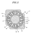
- the laminated core body 6 is provided with a plurality of (e.g., twelve in Fig. 2 ) radial projections 18 which protrude radially outward.
- the bobbins 20 wound with the coil wires 7 are mounted to the respective projections 18 from the radial outer side. As shown in Fig. 2 , in each of recesses 19 between the adjacent projections 18, the side portions of the bobbins 20 mounted to the respective projections 18, at which the winding layers of the coil wires 7 face each other, are disposed in a spaced-apart relationship with each other.
- the bobbins 6 wound with the coil wires 7 are mounted to the laminated core body 6 and are then fixed to the inner circumferential surface of the laminated core ring 5 having an annular shape, thereby forming the stator 2.
- the stator 2 thus formed is mounted to the inner circumferential surface of the frame 4. Thereafter, a resin is introduced into the recesses 19, whereby the bobbins 20 and the coil wires 7 are molded with the resin.
- the rotary electric machine 1 is a rotary induction motor using a three-phase alternating current.
- slot combination in section of the rotary electric machine 1 includes ten poles and twelve slots (10P and 12S) in case of a permanent magnet synchronous motor.
- the bobbins 20 namely, the bobbins 20A and 20B
- the bobbins 20A and 20B corresponding to the coils having the same phase but differing 180 degrees in electrical angle from each other are disposed adjacent to each other.
- U, V and W designate the bobbins 20 corresponding to a U-phase, a V-phase and a W-phase.
- U , V and W designate the bobbins 20 differing 180 degrees in electrical angle from the bobbins U, V and W (This holds true in Fig. 7 ).
- the relationship of the wire connection patterns of individual phases in the substrate 8 to be described below is indicated by double-dot chain lines or single-dot chain lines.
- each of the bobbins 20 the bobbins 20 (twelve bobbins 20 in the present embodiment) mounted to the laminated core body 6 has the same structure. As shown in Figs.
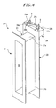
- each of the bobbins 20 includes a substantially quadrilateral frame-like trunk portion (a coil winding portion) 21 wound with the coil wire 7, a first flange portion 22 formed along the edge of one end of the trunk portion 21, a second flange portion 23 formed along the edge of the other end of the trunk portion 21, and a substrate mounting portion 24 installed in the second flange portion 23 to mount thereon the substrate 8 and provided with a terminal fixing portion for fixing the winding starting end portion 7a and the winding finishing end portion 7b of the coil wire 7, which will be described later.
- the trunk portion 21 includes coil winding surfaces 21a opposite to each other in the axial direction 10a of the stator 2 (the left-right direction in Fig. 1 and the up-down direction in Fig. 4 ) and coil winding surfaces 21b opposite to each other in the circumferential direction of the stator 2.
- the trunk portion 21 is formed into a hollow prismatic shape and is provided with a hollow portion 25 into which the projection 18 of the laminated core body 6 is inserted.
- the first flange portion 22 is formed into a rectangular shape extending along the edge of the one end of the trunk portion 21 to open one end of the hollow portion 25.
- the second flange portion 23 is formed into a rectangular shape extending along the edge of the other end of the trunk portion 21 to open the other end of the hollow portion 25.
- the second flange portion 23 protrudes from the trunk portion 21 to be larger in size than the first flange portion 22.
- the substrate mounting portion 24 is provided at one short side (the upper side in Fig. 4 ) of the second flange portion 23.
- Two pin terminals 9 are inserted into the substrate mounting portion 24 to protrude from the upper surface of the substrate mounting portion 24.
- the winding starting end 7a and the winding finishing end 7b of the coil wire 7 are respectively fixed to the pin terminals 9.
- the surface of the substrate mounting portion 24 into which the pin terminals 9 are inserted will be referred to as a "terminal surface 24a".
- bobbin 20A Two kinds of coil winding methods are employed in the bobbins 20 in accordance with the present embodiment. Specifically, in the bobbin 20A shown in Fig. 7 , a winding starting section X from the winding starting end portion 7a of the coil wire 7 to a winding starting position 7c of the trunk portion 21 and a winding finishing section Y from a winding finishing position 7d of the trunk portion 21 to the winding finishing end portion 7b of the coil wire 7 intersect each other when seen in the axial direction 10a.
- the bobbin that employs this coil winding method will be sometimes referred to as "bobbin 20A" (first bobbin) herein below.
- the winding starting section X extending from the winding starting end portion 7a of the coil wire 7 to the winding starting position 7c of the trunk portion 21 and the winding finishing section Y extending from the winding finishing position 7d of the trunk portion 21 to the winding finishing end portion 7b do not intersect each other when seen in the axial direction 10a.
- the bobbin that employs this coil winding method will be sometimes referred to as "bobbin 20B" (second bobbin) herein below.
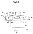
- the terminal surface 24a of the substrate mounting portion 24 has a structure that enables the winding starting section X and the winding finishing section Y of the coil wire 7 to easily intersect each other. Specifically, as shown in Figs. 4 to 6 , a first groove 24b which guides the winding starting section X of the coil wire 7 and a second groove 24c which guides the winding finishing section Y of the coil wire 7 to intersect the winding starting section X are provided in the terminal surface 24a of the substrate mounting portion 24. A third groove 24d and a fourth groove 24e, which respectively guide the winding starting section X and the winding finishing section Y of the coil wire 7 not to intersect each other, are provided in the terminal surface 24a of the substrate mounting portion 24.
- a recess 24h deeper than the grooves 24b to 24d is formed in an end portion of the third groove 24d at the side of the trunk portion 21.
- the recess 24h guides the winding starting section X of the coil wire 7 to the winding starting position 7c of the trunk portion 21.
- the coils 14 guided by the first groove 24b is fitted in the recess 24h.
- a height difference occurs between the winding starting section X and the winding finishing section Y of the coil wire 7. This makes it possible to have the winding starting section X and the winding finishing section Y intersect each other while avoiding mutual interference of the winding starting section X and the winding finishing section Y.
- pin holes 24A to 24D into which the pin terminals 9 are inserted, are formed in the terminal surface 24a of the substrate mounting portion 24.
- the two pin terminals 9 are selectively inserted into one of the pin holes 24A and 24C and one of the pin holes 24B and 24D, respectively.
- the pin holes 24A and 24C are spaced apart by a predetermined distance in the rotation direction of the rotor 3 (in the direction indicated by an arrow A in Fig. 5 ).
- the pin holes 24B and 24D are spaced apart by a predetermined distance in the rotation direction of the rotor 3 (in the direction indicated by the arrow A in Fig. 5 ).
- the pin terminal 9 (first pin) for winding the winding starting end portion 7a of the coil wire 7 is inserted into the pin hole 24A (first pin hole), and the pin terminal 9 (second pin) for winding the winding finishing end portion 7b of the coil wire 7 is inserted into the pin hole 24B (second pin hole).
- the pin terminal 9 (first pin) for winding the winding starting end portion 7a of the coil wire 7 is inserted into the pin hole 24D (first pin hole), and the pin terminal 9 (second pin) for winding the winding finishing end portion 7b of the coil wire 7 is inserted into the pin hole 24C (second pin hole).
- the insertion positions of the pin terminals 9 shown in Fig. 4 correspond to the bobbin 20B.
- the bobbin 20A and the bobbin 20B are alternately arranged to adjoin each other in the circumferential direction.
- the bobbins 20A and 20B corresponding to the coils differing 180 degrees in electrical angle from each other are disposed adjacent to each other.
- the positions of the winding starting end portion 7a and the winding finishing end portion 7b of the coil wire 7 in the bobbin 20A are opposite to those in the bobbin 20B along the rotation direction. Therefore, if the bobbin 20A and the bobbin 20B are disposed adjacent to each other, the winding finishing end portions 7b of the coil wires 7 can adjoin each other in each of the phases.
- Circuit patterns for connecting the coil wires 7 of the respective bobbins 20 in a predetermined pattern are formed in the substrate 8.
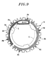
- Fig. 9 shows a circuit pattern formed on a front surface 8A of the substrate 8.
- Fig. 10 shows a circuit pattern formed on a rear surface 8B of the substrate 8.
- reference symbols PU, PV and PW designate wire connection patterns for connecting the winding finishing end portions 7b of the coil wires 7 of the adjacent bobbins 20A and 20B in each of the U-phase, the V-phase and the W-phase.
- Each of the wire connection patterns PU, PV and PW is formed by interconnecting adjacent through-holes 8a.
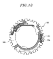
- each of bobbins 30 is configured such that, as in the bobbin 20B of the aforementioned embodiment, the winding starting section X and the winding finishing section Y of the coil wire 7 do not intersect each other when seen in the axial direction 10a. Further, the respective bobbins 30 employ the same coil winding method. For that reason, the positions of the winding starting end portions 7a and the winding finishing end portions 7b of the coil wires 7 in the respective bobbins 30 are in the same positional relationship along the rotation direction. As a result, the degree of freedom in arranging the wire connection patterns in the substrate 8 becomes lower, and the wire connection patterns grow complex.
- the circuit patterns of the substrate 8 into predetermined wire connection patterns by appropriately disposing the bobbins 20A and 20B (namely, by appropriately inverting the positions of the winding starting end portions 7a and the positions of the winding finishing end portions 7b).
- This makes it possible to increase the degree of freedom in arranging the wire connection patterns in the substrate 8. As a result, it becomes possible to simplify the circuit patterns of the substrate 8.
- the respective wire connection patterns PU, PV and PW are formed by interconnecting the adjacent through-holes 8a. This makes it possible to simplify the overall circuit patterns of the substrate 8.
- the substrate 8 As a result of the simplification of the circuit patterns of the substrate 8, it becomes possible, as in the present embodiment, to make the substrate 8 as a double-side substrate in which circuit patterns are formed on the opposite surfaces thereof. Therefore, as compared with a case where the substrate 8 is made from a multi-layer substrate, it is possible to reduce the size of the rotary electric machine 1 and to save the costs. Further, as a result of the simplification of the circuit patterns, it is possible to reduce the arrangement area of the circuit patterns. This makes it possible to increase the space in the substrate 8 in which a resin for molding the bobbins 20 flows. For example, in the substrate 8 shown in Figs. 9 and 10 , as compared with the substrate 38 of the comparative example shown in Figs. 12 and 13 , it is possible to increase the opening area just as much as the space S. Thus, a resin is easy to flow, which makes it possible to reduce generation of molding defects.
- the first groove 24b and the second groove 24c are formed in the terminal surface 24a of the substrate mounting portion 24.
- the first groove 24b guides the winding starting section X of the coil wire 7 of the bobbin 20A.
- the second groove 24c guides the winding finishing section Y of the coil wire 7 of the bobbin 20A.
- the substrate 8 can be mounted on the terminal surface 24a of the substrate mounting portion 24.
- the third groove 24d and the fourth groove 24e are additionally formed on the terminal surface 24a of the substrate mounting portion 24.
- the coil wire 7 can be wound using the first groove 24b and the second groove 24c such that the winding starting section X and the winding finishing section Y intersect each other when seen in the axial direction 10a.
- the coil wire 7 can be wound using the third groove 24d and the fourth groove 24e such that the winding starting section X and the winding finishing section Y do not intersect each other when seen in the axial direction 10a.
- the bobbins of the same shape provide two kinds of bobbins, namely the bobbin 20A in which the winding starting section X and the winding finishing section Y intersect each other when seen in the axial direction 10a and the bobbin 20B in which the winding starting section X and the winding finishing section Y do not intersect each other when seen in the axial direction 10a.
- the bobbins can be manufactured by one kind of mold. Therefore, as compared with a case where the bobbins are manufactured by two kinds of molds, it is possible to save the costs. Since the bobbins 20 of one kind are used, management of the bobbins 20 becomes easier.
- At least two pin holes are provided on the terminal surface 24a of the substrate mounting portion 24.
- the winding starting end portion 7a of the coil wire 7 is wrapped around the pin terminal 9 as the first pin inserted into the pin hole 24A.
- the winding finishing end portion 7b of the coil wire 7 is wrapped around the pin terminal 9 as the second pin inserted into the pin hole 24B.
- pin holes 24A to 24D are provided on the terminal surface 24a of the substrate mounting portion 24.
- Two pin holes 24A and 24C are spaced apart by a predetermined distance in the rotation direction. Accordingly, the position of the winding starting end portion 7a of the coil wire 7 in the bobbin 20A (the position of the winding finishing end portion 7b in the bobbin 20B) can be selected by inserting the pin terminal 9 into one of the pin holes 24A and 24C. Since the other second pin holes 24B and 24D are similarly arranged, it is possible to select the position of the winding finishing end portion 7b in the bobbin 20A (the position of the winding starting end portion 7a in the bobbin 20B).
- the pin hole 24B is selected in the bobbin 20A and the pin hole 24C is selected in the bobbin 20B such that the winding finishing end portions 7b of the coil wires 7 are positioned closer to each other.
- the pin hole 24A is selected for the winding starting end portion 7a of the coil wire 7 in the bobbin 20A and the pin hole 24D is selected for the winding starting end portion 7a of the coil wire 7 in the bobbin 20B such that the winding starting ends 7a of the adjacent coil wires 7 are positioned farther from each other.
- the rotary electric machine 1 is configured to have a slot combination of ten poles and twelve slots (10P-12S).
- 10P-12S ten poles and twelve slots
- the substrate 8 is mounted to the terminal surface 24a of the substrate mounting portion 24.
- a substrate mounting protrusion may be formed on the terminal surface 24a and a gap may be provided between the terminal surface 24a and the substrate 8.
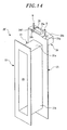
- the bobbin 20' of the present modified example includes a substantially rectangular parallelepiped protrusion 26 arranged on the terminal surface 24a of the substrate mounting portion 24.
- the protrusion 26 has a mounting surface 26a to which the substrate 8 is mounted.
- a gap is formed between the terminal surface 24a and the substrate 8 mounted to the mounting surface 26a of the protrusion 26.
- the gap can be used to wrap the end portion of the coil wire 7.
- grooves 24f and 24g are formed.
- the groove 24f is a groove that guides the winding starting section X or the winding finishing section Y of the coil wire 7.
- the groove 24g is a groove that guides the winding finishing section Y of the coil wire 7.
- three pin holes 24A, 24B and 24C for the insertion of the pin terminals 9 are formed on the terminal surface 24a, and the pin hole 24D is not formed.
- Other configurations of the bobbin 20' in accordance with the present modified example are the same as the configurations of the bobbin 20 of the aforementioned embodiment and, therefore, will not be described herein.
- Fig. 16 shows a bobbin 20'A in which the winding starting section X and the winding finishing section Y of the coil wire 7 intersect each other when seen in the axial direction.
- the pin terminal 9 (the first pin) around which the winding starting end portion 7a of the coil wire 7 is wrapped is inserted into the pin hole 24A (the first pin hole).
- the pin terminal 9 (the second pin) around which the winding finishing end portion 7b of the coil wire 7 is wrapped is inserted into the pin hole 24B (the second pin hole).
- the winding starting section X of the coil wire 7 is drawn to the groove 24f around the protrusion 26 and is guided to the winding starting position 7c of the trunk portion 21 by the grooves 24f and 24h.
- the winding finishing section Y of the coil wire 7 is a section extending from the winding finishing position 7d of the trunk portion 21 corresponding to one corner of the protrusion 26 to the winding finishing end portion 7b.
- the recess 24h enables the winding starting section X and the winding finishing section Y to intersect each other while avoiding mutual interference.
- the insertion positions of the pin terminals 9 shown in Fig. 14 correspond to the bobbin 20'A.
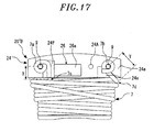
- Fig. 17 shows a bobbin 20'B in which the winding starting section X and the winding finishing section Y of the coil wire 7 do not intersect each other when seen in the axial direction.
- the pin terminal 9 (the first pin) around which the winding starting end portion 7a of the coil wire 7 is wrapped is inserted into the pin hole 24B (the first pin hole).
- the pin terminal 9 (the second pin) around which the winding finishing end portion 7b of the coil wire 7 is wrapped is inserted into the pin hole 24C (the second pin hole).
- the bobbins 20'A and 20'B employing two kinds of coil winding methods can be provided using one kind of bobbin 20'. It is therefore possible to obtain the same effects as available in the aforementioned embodiment.
- the installation of the protrusion 26 eliminates the need to form the first groove 24b and the second groove 24c intersecting each other when seen in the axial direction 10a, which are employed in the aforementioned embodiment. This makes it possible to simplify the configuration of the bobbins.
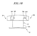
- the bobbins 20A and 20B are provided using the common bobbins 20.
- the bobbin 20B is configured such that the winding starting section X and the winding finishing section Y of the coil wire 7 do not intersect each other when seen in the axial direction 10a
- the bobbin 20C includes two grooves 24f and 24g and two pin holes 24F and 24G.
- the winding starting section X of the coil wire 7 is guided by the groove 24f while the winding finishing section Y is guided by the groove 24g.
- the winding starting section X and the winding finishing section Y of the coil wire 7 can be configured not to intersect each other when seen in the axial direction 10a.
Landscapes
- Engineering & Computer Science (AREA)
- Power Engineering (AREA)
- Insulation, Fastening Of Motor, Generator Windings (AREA)
- Iron Core Of Rotating Electric Machines (AREA)
- Windings For Motors And Generators (AREA)
Applications Claiming Priority (1)
| Application Number | Priority Date | Filing Date | Title |
|---|---|---|---|
| JP2013105636A JP5858245B2 (ja) | 2013-05-17 | 2013-05-17 | ボビン及び回転電機 |
Publications (2)
| Publication Number | Publication Date |
|---|---|
| EP2804294A2 true EP2804294A2 (de) | 2014-11-19 |
| EP2804294A3 EP2804294A3 (de) | 2016-07-20 |
Family
ID=50238274
Family Applications (1)
| Application Number | Title | Priority Date | Filing Date |
|---|---|---|---|
| EP14158782.4A Withdrawn EP2804294A3 (de) | 2013-05-17 | 2014-03-11 | Spulenträger und elektrische Drehmaschine mit derartigem Spulenträger |
Country Status (6)
| Country | Link |
|---|---|
| US (1) | US9748813B2 (de) |
| EP (1) | EP2804294A3 (de) |
| JP (1) | JP5858245B2 (de) |
| KR (1) | KR101606262B1 (de) |
| CN (1) | CN104167847B (de) |
| BR (1) | BR102014006570A2 (de) |
Cited By (1)
| Publication number | Priority date | Publication date | Assignee | Title |
|---|---|---|---|---|
| FR3094585A1 (fr) * | 2019-03-25 | 2020-10-02 | Valeo Japan Co. Ltd. | Elément isolant de tête de bobine d’un stator de machine électrique tournante, stator et machine électrique tournante correspondants. |
Families Citing this family (12)
| Publication number | Priority date | Publication date | Assignee | Title |
|---|---|---|---|---|
| US9480415B2 (en) | 2013-04-26 | 2016-11-01 | Medtronic Navigation, Inc. | Electromagnetic coil apparatuses for surgical navigation and corresponding methods |
| US11096605B2 (en) | 2015-03-31 | 2021-08-24 | Medtronic Navigation, Inc. | Modular coil assembly |
| TW201707351A (zh) * | 2015-08-13 | 2017-02-16 | 建準電機工業股份有限公司 | 線圈繞組及其繞線套 |
| JP6304175B2 (ja) * | 2015-08-19 | 2018-04-04 | 株式会社デンソー | 電動機 |
| JP6831615B2 (ja) * | 2016-07-28 | 2021-02-17 | 三星電子株式会社Samsung Electronics Co.,Ltd. | ステータ及びブラシレスモータ |
| CN110034640B (zh) * | 2018-01-12 | 2020-07-28 | 日本电产三协电子(东莞)有限公司 | 马达的制造方法 |
| CN110880823A (zh) * | 2018-09-05 | 2020-03-13 | 光宝电子(广州)有限公司 | 绝缘套管、使用其的定子单元结构和伺服马达结构 |
| JP7620505B2 (ja) | 2021-06-15 | 2025-01-23 | 株式会社ミツバ | インシュレータ、ステータ及び電動モータ |
| WO2022269672A1 (ja) * | 2021-06-21 | 2022-12-29 | 住友電気工業株式会社 | モータ、及び配線部材 |
| FR3127656B1 (fr) * | 2021-09-30 | 2023-09-29 | Valeo Systemes Dessuyage | Bobine pour stator de moteur électrique, stator associé et procédé de fabrication associé |
| GB2619413B8 (en) * | 2023-05-18 | 2024-11-20 | High Tech Battery Inc | Axial flux machine and stator for axial flux machine |
| CN121620854A (zh) | 2023-08-31 | 2026-03-06 | 株式会社安川电机 | 马达及马达制造方法 |
Citations (1)
| Publication number | Priority date | Publication date | Assignee | Title |
|---|---|---|---|---|
| JPH09308142A (ja) | 1996-05-20 | 1997-11-28 | Yaskawa Electric Corp | 回転電機 |
Family Cites Families (16)
| Publication number | Priority date | Publication date | Assignee | Title |
|---|---|---|---|---|
| JPH09219964A (ja) * | 1996-02-13 | 1997-08-19 | Yaskawa Electric Corp | ブラシレスモータおよびその巻線方法 |
| JP3478744B2 (ja) * | 1998-11-27 | 2003-12-15 | 松下エコシステムズ株式会社 | 電動機の固定子 |
| JP3664608B2 (ja) * | 1999-05-25 | 2005-06-29 | 三菱電機株式会社 | 回転電機 |
| US6856055B2 (en) * | 2002-07-11 | 2005-02-15 | Emerson Electric Co. | Interconnecting ring and wire guide |
| JP4112535B2 (ja) * | 2004-07-30 | 2008-07-02 | 株式会社一宮電機 | ステータ及びブラシレスモータ |
| JP4931449B2 (ja) | 2006-03-22 | 2012-05-16 | 日本電産サンキョー株式会社 | モータ |
| JP2008263691A (ja) * | 2007-04-11 | 2008-10-30 | Minebea Co Ltd | 小径ステッピングモータ、そのボビン、及びそのモータの組立方法 |
| JP4962127B2 (ja) * | 2007-05-02 | 2012-06-27 | 住友電気工業株式会社 | インシュレータ |
| RU2352048C1 (ru) * | 2007-08-08 | 2009-04-10 | Закрытое акционерное общество "ИРИС" | Вентильный индукторно-реактивный двигатель |
| JP5237049B2 (ja) * | 2008-10-28 | 2013-07-17 | アスモ株式会社 | インシュレータ、ステータ及びステータの製造方法 |
| JP5478117B2 (ja) * | 2009-05-21 | 2014-04-23 | アスモ株式会社 | モータ |
| DE102010004887A1 (de) * | 2010-01-18 | 2011-07-21 | Tyco Electronics Belgium Ec Bvba | Spulenkörper zur Montage an einem Magnetkern, Magnetkern für Reluktanzresolver und Verfahren zur Herstellung |
| US8736129B2 (en) * | 2010-10-21 | 2014-05-27 | Emerson Electric Co. | End caps for stator segments of segmented stator assemblies |
| JP2012105372A (ja) * | 2010-11-05 | 2012-05-31 | Honda Motor Co Ltd | 外転型の電動機 |
| JP5267541B2 (ja) * | 2010-11-11 | 2013-08-21 | 株式会社安川電機 | ボビン及び回転電機 |
| JP5418484B2 (ja) * | 2010-12-08 | 2014-02-19 | 三菱電機株式会社 | 回転電機の固定子のコイルボビンおよびこのコイルボビンを使用した回転電機の固定子の巻線方法 |
-
2013
- 2013-05-17 JP JP2013105636A patent/JP5858245B2/ja active Active
-
2014
- 2014-03-11 EP EP14158782.4A patent/EP2804294A3/de not_active Withdrawn
- 2014-03-17 KR KR1020140031119A patent/KR101606262B1/ko active Active
- 2014-03-19 BR BRBR102014006570-9A patent/BR102014006570A2/pt not_active IP Right Cessation
- 2014-03-19 CN CN201410102471.3A patent/CN104167847B/zh active Active
- 2014-03-20 US US14/220,135 patent/US9748813B2/en active Active
Patent Citations (1)
| Publication number | Priority date | Publication date | Assignee | Title |
|---|---|---|---|---|
| JPH09308142A (ja) | 1996-05-20 | 1997-11-28 | Yaskawa Electric Corp | 回転電機 |
Cited By (2)
| Publication number | Priority date | Publication date | Assignee | Title |
|---|---|---|---|---|
| FR3094585A1 (fr) * | 2019-03-25 | 2020-10-02 | Valeo Japan Co. Ltd. | Elément isolant de tête de bobine d’un stator de machine électrique tournante, stator et machine électrique tournante correspondants. |
| EP3949085A4 (de) * | 2019-03-25 | 2023-06-07 | Valeo Japan Co., Ltd. | Isolierelement für wickelköpfe eines stators einer rotierenden elektrischen maschine sowie entsprechender stator und rotierende elektrische maschine |
Also Published As
| Publication number | Publication date |
|---|---|
| JP5858245B2 (ja) | 2016-02-10 |
| US20140339935A1 (en) | 2014-11-20 |
| BR102014006570A2 (pt) | 2015-06-02 |
| CN104167847B (zh) | 2017-05-17 |
| US9748813B2 (en) | 2017-08-29 |
| JP2014230305A (ja) | 2014-12-08 |
| KR101606262B1 (ko) | 2016-03-24 |
| KR20140135913A (ko) | 2014-11-27 |
| EP2804294A3 (de) | 2016-07-20 |
| CN104167847A (zh) | 2014-11-26 |
Similar Documents
| Publication | Publication Date | Title |
|---|---|---|
| US9748813B2 (en) | Bobbin and rotary electric machine | |
| US8610328B2 (en) | Rotary electric machine | |
| EP2273654B1 (de) | Elektrische Drehmaschine und Herstellungsverfahren dafür | |
| US10536046B2 (en) | Rotary electric machine with stator having bus bars with recesses and bus bar holder with protrusions engaged with the recesses | |
| JP6033582B2 (ja) | ステータおよびステータの製造方法 | |
| CN103548244B (zh) | 旋转电机及其制造方法 | |
| EP2833520B1 (de) | Stator | |
| JP2004229459A (ja) | 回転電機の集中巻きステータコイル | |
| KR20080021678A (ko) | 회전 전동기의 전기자, 회전 전동기 및 그 제조 방법 | |
| WO2019004116A1 (ja) | ステータ、モータおよびステータの製造方法 | |
| EP2031735B1 (de) | Stator und elektrischer Motor | |
| JP5998871B2 (ja) | 回転電機のステータ | |
| JP5111887B2 (ja) | 回転電機の固定子 | |
| JP2019103354A (ja) | 回転電機 | |
| KR20220007448A (ko) | 모터용 버스바 유닛 | |
| CN203722367U (zh) | 旋转电机 | |
| JP7019452B2 (ja) | ステータおよび回転電機 | |
| WO2018168108A1 (ja) | 回転電機 | |
| JP6488100B2 (ja) | 電動モータ | |
| JP2019103298A (ja) | 回転電機 | |
| CN110710085A (zh) | 定子和马达 | |
| JP2020150715A (ja) | 電機子 |
Legal Events
| Date | Code | Title | Description |
|---|---|---|---|
| PUAI | Public reference made under article 153(3) epc to a published international application that has entered the european phase |
Free format text: ORIGINAL CODE: 0009012 |
|
| 17P | Request for examination filed |
Effective date: 20140311 |
|
| AK | Designated contracting states |
Kind code of ref document: A2 Designated state(s): AL AT BE BG CH CY CZ DE DK EE ES FI FR GB GR HR HU IE IS IT LI LT LU LV MC MK MT NL NO PL PT RO RS SE SI SK SM TR |
|
| AX | Request for extension of the european patent |
Extension state: BA ME |
|
| PUAL | Search report despatched |
Free format text: ORIGINAL CODE: 0009013 |
|
| AK | Designated contracting states |
Kind code of ref document: A3 Designated state(s): AL AT BE BG CH CY CZ DE DK EE ES FI FR GB GR HR HU IE IS IT LI LT LU LV MC MK MT NL NO PL PT RO RS SE SI SK SM TR |
|
| AX | Request for extension of the european patent |
Extension state: BA ME |
|
| RIC1 | Information provided on ipc code assigned before grant |
Ipc: H02K 1/14 20060101ALN20160610BHEP Ipc: H02K 3/34 20060101AFI20160610BHEP |
|
| STAA | Information on the status of an ep patent application or granted ep patent |
Free format text: STATUS: THE APPLICATION IS DEEMED TO BE WITHDRAWN |
|
| 18D | Application deemed to be withdrawn |
Effective date: 20170121 |