EP2803827B2 - Metallic hollow valve - Google Patents
Metallic hollow valve Download PDFInfo
- Publication number
- EP2803827B2 EP2803827B2 EP14152509.7A EP14152509A EP2803827B2 EP 2803827 B2 EP2803827 B2 EP 2803827B2 EP 14152509 A EP14152509 A EP 14152509A EP 2803827 B2 EP2803827 B2 EP 2803827B2
- Authority
- EP
- European Patent Office
- Prior art keywords
- cavity
- valve
- hollow valve
- hollow
- internal combustion
- Prior art date
- Legal status (The legal status is an assumption and is not a legal conclusion. Google has not performed a legal analysis and makes no representation as to the accuracy of the status listed.)
- Active
Links
- 238000002485 combustion reaction Methods 0.000 claims description 22
- 229910000831 Steel Inorganic materials 0.000 claims description 6
- 239000010959 steel Substances 0.000 claims description 6
- 230000003746 surface roughness Effects 0.000 claims description 6
- 238000001816 cooling Methods 0.000 description 6
- 238000004519 manufacturing process Methods 0.000 description 5
- 239000002826 coolant Substances 0.000 description 4
- 239000000446 fuel Substances 0.000 description 4
- 239000007789 gas Substances 0.000 description 4
- 238000000034 method Methods 0.000 description 4
- 229910045601 alloy Inorganic materials 0.000 description 3
- 239000000956 alloy Substances 0.000 description 3
- 229910052751 metal Inorganic materials 0.000 description 3
- 239000002184 metal Substances 0.000 description 3
- DGAQECJNVWCQMB-PUAWFVPOSA-M Ilexoside XXIX Chemical compound C[C@@H]1CC[C@@]2(CC[C@@]3(C(=CC[C@H]4[C@]3(CC[C@@H]5[C@@]4(CC[C@@H](C5(C)C)OS(=O)(=O)[O-])C)C)[C@@H]2[C@]1(C)O)C)C(=O)O[C@H]6[C@@H]([C@H]([C@@H]([C@H](O6)CO)O)O)O.[Na+] DGAQECJNVWCQMB-PUAWFVPOSA-M 0.000 description 2
- 230000006835 compression Effects 0.000 description 2
- 238000007906 compression Methods 0.000 description 2
- 230000007797 corrosion Effects 0.000 description 2
- 238000005260 corrosion Methods 0.000 description 2
- 230000001419 dependent effect Effects 0.000 description 2
- 230000017525 heat dissipation Effects 0.000 description 2
- 239000000203 mixture Substances 0.000 description 2
- 239000003921 oil Substances 0.000 description 2
- 230000008092 positive effect Effects 0.000 description 2
- 229910052708 sodium Inorganic materials 0.000 description 2
- 239000011734 sodium Substances 0.000 description 2
- 239000000126 substance Substances 0.000 description 2
- 229910000851 Alloy steel Inorganic materials 0.000 description 1
- 235000014443 Pyrus communis Nutrition 0.000 description 1
- 239000000567 combustion gas Substances 0.000 description 1
- 239000012530 fluid Substances 0.000 description 1
- 238000005242 forging Methods 0.000 description 1
- 238000003754 machining Methods 0.000 description 1
- 230000035939 shock Effects 0.000 description 1
Images
Classifications
-
- F—MECHANICAL ENGINEERING; LIGHTING; HEATING; WEAPONS; BLASTING
- F01—MACHINES OR ENGINES IN GENERAL; ENGINE PLANTS IN GENERAL; STEAM ENGINES
- F01L—CYCLICALLY OPERATING VALVES FOR MACHINES OR ENGINES
- F01L3/00—Lift-valve, i.e. cut-off apparatus with closure members having at least a component of their opening and closing motion perpendicular to the closing faces; Parts or accessories thereof
- F01L3/20—Shapes or constructions of valve members, not provided for in preceding subgroups of this group
-
- F—MECHANICAL ENGINEERING; LIGHTING; HEATING; WEAPONS; BLASTING
- F01—MACHINES OR ENGINES IN GENERAL; ENGINE PLANTS IN GENERAL; STEAM ENGINES
- F01L—CYCLICALLY OPERATING VALVES FOR MACHINES OR ENGINES
- F01L3/00—Lift-valve, i.e. cut-off apparatus with closure members having at least a component of their opening and closing motion perpendicular to the closing faces; Parts or accessories thereof
- F01L3/12—Cooling of valves
- F01L3/14—Cooling of valves by means of a liquid or solid coolant, e.g. sodium, in a closed chamber in a valve
Definitions
- the present invention relates to a metallic hollow valve of an internal combustion engine with a tubular shaft and a valve plate connected thereto according to the preamble of claim 1.
- From the DE 10 2010 051 871 A1 discloses a method for producing metal hollow valves for the gas exchange of an internal combustion engine, the cavities of the hollow parts forming the valve being connected to one another and these cavities being produced at least partially by electrochemical metal removal.
- the valve stem is first drilled through lengthwise, with the cavity in the valve head then being produced as an expansion bore transverse to the longitudinal axis of the valve stem.
- the production of hollow valves should be simplified by means of the method described and at the same time their quality should be able to be improved.
- a method for producing a metallic hollow valve of an internal combustion engine in which a bore is made in a blank designed as a forging pear. A subsequent valve head is then at least partially hollowed out by electrochemical removal, with the cavity produced in this way then being filled by means of a supporting fluid and the hollow valve being closed.
- the hollow valve can be manufactured comparatively inexpensively.
- metallic hollow valves are lighter than full valves and offer improved heat dissipation when filled with a cooling medium such as sodium.
- a hollow valve which offers particularly good heat dissipation, leads to a shift in the knock limit and thus to particularly advantageous operation.
- Knocking is the uncontrolled ignition of the fuel-air mixture due to excessive temperature and pressure. This leads to shocks in the internal combustion engine with high mechanical and thermal loads, which ultimately have a negative impact on service life and efficiency.
- the knock limit can be raised, higher compression in the cylinder is possible, which leads to a significant increase in efficiency in the combustion process and thus to higher performance with lower fuel consumption.
- the present invention is therefore concerned with the problem of specifying an improved embodiment for a metallic hollow valve of the generic type, which allows an increased knock limit.
- the present invention is based on the general idea of raising the knock limit in an internal combustion engine by designing the valves (gas exchange valves) used in this internal combustion engine as very thin-walled hollow valves and thereby cooling them particularly effectively.
- the metallic hollow valve according to the invention has, in a known manner, a tubular shaft and a valve head connected thereto.
- the shaft has an outside diameter of between 5.0 and 6.0 mm and an inside diameter of between 3.0 and 4.6 mm, as a result of which the wall thickness of the shaft can be significantly reduced in comparison to conventional hollow valves.
- a cavity is also provided in the valve head, with the walls surrounding it having a thickness of between 1.0 and at most 2.0 mm, thereby also enabling high heat transfer and excellent cooling of the hollow valve.
- the cavity in the valve head is produced by electrochemical removal, with the cavity being essentially round, ellipsoidal or conical is trained. Electrochemical removal offers the possibility of creating the largest possible cavity in the valve head without great mechanical effort and without the use of complicated tools.
- the electrochemical removal represents a process that can be controlled extremely precisely, so that the metallic hollow valves according to the invention can be produced with consistently high quality.
- the shank can also be expanded by electrochemical removal, in which case it is usually drilled first.
- a surface roughness R Z of an inner wall of the cavity is expediently >10 ⁇ m, in particular R Z >16 ⁇ m. Due to the comparatively large surface roughness on the inner wall of the cavity in the valve head, an enlarged heat transfer surface is available, which has a positive effect on heat exchange and thus also on the cooling of the hollow valves according to the invention.
- the surface roughness of an inner wall in the shaft of the hollow valve is designed in the same way.
- the hollow valve is made of X45CrSi9-3, X50CrMnNiNbN21-9, NiCr20TiAl, or NCF 3015 (Ni 30%, Cr 15%) steel.
- Such high-alloy steels allow the filigree design of the hollow valve according to the invention and also have a comparatively high wear resistance.
- such high-alloy steels usually have high corrosion resistance and in particular also high resistance to aggressive chemicals such as oils or combustion exhaust gases, so that they are particularly suitable for use in such metallic hollow valves in internal combustion engines.
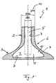
- the only figure 1 shows a cross section through a metallic hollow valve according to the invention.
- a metallic hollow valve 1 according to the invention of an internal combustion engine (otherwise not shown) has a tubular shaft 2 and a valve head 3 connected thereto.
- the shaft 2 and the valve head 3 are usually designed in one piece.
- it is filigree, i.e. it is equipped with comparatively thin wall thicknesses b 1 , b 2 and b 3 , the wall thickness b 1 being in the area of a valve head base facing a combustion chamber (not shown).
- the wall thickness b 2 is measured in the area of a valve throat 6 .
- the wall thickness b 3 refers to the thickness of the wall in the area of the shaft 2.
- the thin wall thicknesses b 1 , b 2 and b 3 not only improve the cooling of the metallic hollow valve 1, but also increase the knock limit of the internal combustion engine , whereby an uncontrolled ignition of a gasoline-air mixture with the associated high mechanical and thermal loads can be avoided, or at least greatly reduced.
- the thin walls increase the knock limit.
- the metal hollow valve 1 according to the invention has an outside diameter d a of between 5 and 6 mm in the area of its shaft 2 .
- An inner diameter d i in the area of the shaft 2 is between 3.0 and 4.6 mm, so that the wall thickness b 3 is between approximately 0.7 and 1.5 mm.
- the wall thickness b 3 can also be between about 0.5 and 1.5 mm due to tolerances, with the inner diameter d i preferably being 4.6 mm if the outer diameter d a is 6 mm.
- a cavity 4 is provided in the valve head 3, which together with a cavity 5 arranged in the shaft 2 forms a receiving space for a coolant, for example sodium.
- a wall surrounding the cavity 4 has a thickness b 1 of between 1 and 2 mm in the area of the valve head base, as well as in the area of a valve throat 6, so that the thickness b 2 of the wall is also approximately 1 to 2 mm in this area.
- the surface roughness R Z of an inner wall 7 of the cavity 4 and of the cavity 5 is greater than 10 ⁇ m, in particular greater than 16 ⁇ m is.
- the increased surface roughness R Z increases the area available for heat exchange and thus improves heat transfer.
- the hollow valve 1 can be made of a high-alloy steel, such as X45CrSi9-3, X50CrMnNiNbN21-9, NiCr20TiAl or NCF3015 steel.
- a high-alloy steel such as X45CrSi9-3, X50CrMnNiNbN21-9, NiCr20TiAl or NCF3015 steel.
- Such high-alloy steels allow the filigree design of the metallic hollow valve 1 according to the invention and are also resistant to aggressive chemical media such as oils or combustion gases. In addition, they have a high wear and corrosion resistance and thus have a long service life.
- the cavity 5 in the stem 2 is usually drilled, whereas the cavity 4 in the valve head 3 is produced by means of electrochemical machining.
- the cavity 4 can, for example, be round, conical or ellipsoidal. Such an electrochemical Removal enables the cavity 4 and thus also the walls surrounding it to be produced in a simple manner on the one hand and highly accurately on the other.
- this can be cooled significantly better and thereby indirectly raise the knock limit of the internal combustion engine, which not only increases the service life of the internal combustion engine but also leads to higher performance with lower fuel consumption at the same time.
- the filigree design also saves weight, which has a positive effect on the fuel consumption of the internal combustion engine.
Description
Die vorliegende Erfindung betrifft ein metallisches Hohlventil einer Brennkraftmaschine mit einem rohrförmigen Schaft und einem daran angebundenen Ventilteller gemäß dem Oberbegriff des Anspruchs 1.The present invention relates to a metallic hollow valve of an internal combustion engine with a tubular shaft and a valve plate connected thereto according to the preamble of
Die zunehmenden thermischen Belastungen in Verbrennungsmotoren, insbesondere in PKW-Motoren, erfordern es zunehmend, auch Bestandteile derselben, wie beispielsweise die Gaswechselventile, kurz auch Ventile genannt, zu kühlen. Hierfür werden sogenannten Hohlventile mit einem innenliegenden Kühlmedium verwendet.The increasing thermal loads in internal combustion engines, in particular in passenger car engines, increasingly require components thereof, such as the gas exchange valves, also called valves for short, to cool. So-called hollow valves with an internal cooling medium are used for this purpose.
Aus der
Aus der
Aus der
Aus der
Aus der
Generell gilt für metallische Hohlventile, dass diese leichter sind als Vollventile und bei Füllung mit einem Kühlmedium, wie beispielsweise Natrium, eine verbesserte Wärmeabfuhr bieten. Bei Ottomotoren führt ein Hohlventil, das eine besonders gute Wärmeableitung bietet, zu einer Verschiebung der Klopfgrenze und damit zu einem besonders vorteilhaften Betrieb. Das Klopfen bezeichnet das unkontrollierte Zünden des Benzin-Luft-Gemisches aufgrund zu hoher Temperatur und Druck. Dies führt zu Schlägen in der Brennkraftmaschine mit hohen mechanischen und thermischen Belastungen, welche schlussendlich die Lebensdauer und den Wirkungsgrad negativ beeinträchtigen. Kann die Klopfgrenze jedoch angehoben werden, wird eine höhere Verdichtung im Zylinder möglich, die zu einer deutlichen Effizienzsteigerung im Verbrennungsprozess und damit zu einer höheren Leistung bei geringerem Kraftstoffverbrauch führt.In general, metallic hollow valves are lighter than full valves and offer improved heat dissipation when filled with a cooling medium such as sodium. In gasoline engines, a hollow valve, which offers particularly good heat dissipation, leads to a shift in the knock limit and thus to particularly advantageous operation. Knocking is the uncontrolled ignition of the fuel-air mixture due to excessive temperature and pressure. This leads to shocks in the internal combustion engine with high mechanical and thermal loads, which ultimately have a negative impact on service life and efficiency. However, if the knock limit can be raised, higher compression in the cylinder is possible, which leads to a significant increase in efficiency in the combustion process and thus to higher performance with lower fuel consumption.
Die vorliegende Erfindung beschäftigt sich daher mit dem Problem, für ein metallisches Hohlventil der gattungsgemäßen Art eine verbesserte Ausführungsform anzugeben, die eine erhöhte Klopfgrenze ermöglicht.The present invention is therefore concerned with the problem of specifying an improved embodiment for a metallic hollow valve of the generic type, which allows an increased knock limit.
Dieses Problem wird erfindungsgemäß durch den Gegenstand des unabhängigen Anspruchs 1 gelöst. Vorteilhafte Ausführungsformen sind Gegenstand der abhängigen Ansprüche.According to the invention, this problem is solved by the subject matter of
Die vorliegende Erfindung beruht auf dem allgemeinen Gedanken, die Klopfgrenze in einer Brennkraftmaschine anzuheben, indem die in dieser Brennkraftmaschine eingesetzten Ventile (Gaswechselventile) als sehr dünnwandige Hohlventile ausgebildet werden und dadurch besonders effektiv zu kühlen sind. Das erfindungsgemäße metallische Hohlventil weist hierzu in bekannter Weise einen rohrförmigen Schaft sowie einen daran angebundenen Ventilkopf auf. Der Schaft besitzt erfindungsgemäß einen Außendurchmesser zwischen 5,0 und 6,0 mm sowie einen Innendurchmesser zwischen 3,0 und 4,6 mm, wodurch eine Wandstärke des Schaftes im Vergleich zu herkömmlichen Hohlventilen deutlich reduziert werden kann. Im Ventilkopf ist zusätzlich ein Hohlraum vorgesehen, wobei die diesen umgebenden Wände eine Dicke zwischen 1,0 und maximal 2,0 mm aufweist und dadurch ebenfalls eine hohe Wärmeübertragung und eine exzellente Kühlung des Hohlventils ermöglicht. Durch die vergleichsweise filigrane Ausbildung des erfindungsgemäßen Hohlventils kann insbesondere eine effektive Kühlung an der planen und dem Brennraum zugewandten Ventilkopfunterseite erreicht werden, welche dazu beiträgt, die Klopfgrenze zu verschieben, das heißt anzuheben, und dadurch die mechanischen und thermischen Belastungen der Brennkraftmaschine, hervorgerufen durch das Klopfen, zu senken. In dem erfindungsgemäßen filigranen Ventil kann darüber hinaus eine höhere Verdichtung im Zylinder erzielt werden, die zu einer deutlichen Effizienzsteigerung im Verbrennungsprozess und damit zu einer höheren Leistung bei gleichzeitig geringerem Kraftstoffverbrauch führt. Dabei ist der Hohlraum im Ventilkopf durch elektrochemisches Abtragen hergestellt, wobei der Hohlraum im Wesentlichen rund, ellipsoidisch oder kegelförmig ausgebildet ist. Das elektrochemische Abtragen bietet dabei die Möglichkeit, ohne großen mechanischen Aufwand und ohne Einsatz komplizierter Werkzeuge einen möglichst großen Hohlraum im Ventilkopf zu schaffen. Das elektrochemische Abtragen stellt dabei einen äußerst genau kontrollierbaren Prozess dar, sodass die erfindungsgemäßen metallischen Hohlventile mit gleichbleibend hoher Qualität hergestellt werden können. Der Schaft kann dabei ebenfalls durch elektrochemisches Abtragen erweitert werden, wobei dieser üblicherweise zunächst gebohrt wird.The present invention is based on the general idea of raising the knock limit in an internal combustion engine by designing the valves (gas exchange valves) used in this internal combustion engine as very thin-walled hollow valves and thereby cooling them particularly effectively. For this purpose, the metallic hollow valve according to the invention has, in a known manner, a tubular shaft and a valve head connected thereto. According to the invention, the shaft has an outside diameter of between 5.0 and 6.0 mm and an inside diameter of between 3.0 and 4.6 mm, as a result of which the wall thickness of the shaft can be significantly reduced in comparison to conventional hollow valves. A cavity is also provided in the valve head, with the walls surrounding it having a thickness of between 1.0 and at most 2.0 mm, thereby also enabling high heat transfer and excellent cooling of the hollow valve. Due to the comparatively filigree design of the hollow valve according to the invention, effective cooling can be achieved in particular on the flat valve head underside facing the combustion chamber, which contributes to shifting the knock limit, i.e. raising it, and thereby reducing the mechanical and thermal loads on the internal combustion engine caused by the knock to lower. In addition, in the filigree valve according to the invention, a higher compression in the cylinder can be achieved, which leads to a significant increase in efficiency in the combustion process and thus to higher performance with lower fuel consumption at the same time. The cavity in the valve head is produced by electrochemical removal, with the cavity being essentially round, ellipsoidal or conical is trained. Electrochemical removal offers the possibility of creating the largest possible cavity in the valve head without great mechanical effort and without the use of complicated tools. The electrochemical removal represents a process that can be controlled extremely precisely, so that the metallic hollow valves according to the invention can be produced with consistently high quality. The shank can also be expanded by electrochemical removal, in which case it is usually drilled first.
Zweckmäßig beträgt eine Oberflächenrauheit RZ einer Innenwand des Hohlraums > 10 µm, insbesondere RZ > 16 µm. Durch die vergleichsweise große Oberflächenrauheit an der Innenwand des Hohlraums im Ventilkopf steht eine vergrößerte Wärmeübertragungsfläche zur Verfügung, die einen Wärmetausch positiv beeinflusst und damit auch die Kühlung der erfindungsgemäßen Hohlventile. In gleicher Weise ist auch die Oberflächenrauheit einer Innenwand im Schaft des Hohlventils gestaltet.A surface roughness R Z of an inner wall of the cavity is expediently >10 μm, in particular R Z >16 μm. Due to the comparatively large surface roughness on the inner wall of the cavity in the valve head, an enlarged heat transfer surface is available, which has a positive effect on heat exchange and thus also on the cooling of the hollow valves according to the invention. The surface roughness of an inner wall in the shaft of the hollow valve is designed in the same way.
Bei einer weiteren vorteilhaften Ausführungsform der erfindungsgemäßen Lösung ist das Hohlventil aus X45CrSi9-3, aus X50CrMnNiNbN21-9, aus NiCr20TiAl, oder aus NCF 3015 (Ni 30%, Cr 15%) Stahl hergestellt. Derartige hochlegierte Stähle erlauben erst die filigrane Ausbildung des erfindungsgemäßen Hohlventils und weisen darüber hinaus einen vergleichsweise hohen Verschleißwiderstand auf. Derartige hochlegierte Stähle besitzen darüber hinaus üblicherweise eine hohe Korrosionsbeständigkeit und insbesondere auch eine hohe Beständigkeit gegen aggressive Chemikalien, wie beispielsweise Öle oder Verbrennungsabgase, sodass sie besonders geeignet für den Einsatz bei derartigen metallischen Hohlventile in Brennkraftmaschinen sind.In a further advantageous embodiment of the solution according to the invention, the hollow valve is made of X45CrSi9-3, X50CrMnNiNbN21-9, NiCr20TiAl, or NCF 3015 (Ni 30%, Cr 15%) steel. Such high-alloy steels allow the filigree design of the hollow valve according to the invention and also have a comparatively high wear resistance. In addition, such high-alloy steels usually have high corrosion resistance and in particular also high resistance to aggressive chemicals such as oils or combustion exhaust gases, so that they are particularly suitable for use in such metallic hollow valves in internal combustion engines.
Weitere wichtige Merkmale und Vorteile der Erfindung ergeben sich aus den Unteransprüchen, aus der Zeichnung und aus der zugehörigen Figurenbeschreibung anhand der Zeichnung.Further important features and advantages of the invention result from the dependent claims, from the drawing and from the associated description of the figures based on the drawing.
Es versteht sich, dass die vorstehend genannten und die nachstehend noch zu erläuternden Merkmale nicht nur in der jeweils angegebenen Kombination, sondern auch in anderen Kombinationen oder in Alleinstellung verwendbar sind, ohne den Rahmen der vorliegenden Erfindung zu verlassen.It goes without saying that the features mentioned above and those still to be explained below can be used not only in the combination specified in each case, but also in other combinations or on their own, without departing from the scope of the present invention.
Ein bevorzugtes Ausführungsbeispiel der Erfindung ist in der Zeichnung dargestellt und wird in der nachfolgenden Beschreibung näher erläutert.A preferred embodiment of the invention is shown in the drawing and is explained in more detail in the following description.
Die einzige
Entsprechend der
Um die Wärmeübertragung zwischen dem im Hohlraum 4 und 5 angeordneten Kühlmittel und dem metallischen Hohlventil 1 weiter verbessern zu können, kann vorgesehen sein, dass eine Oberflächenrauheit RZ einer Innenwand 7 des Hohlraums 4 und des Hohlraums 5 größer als 10 µm, insbesondere größer als 16 µm ist. Durch die erhöhte Oberflächenrauheit RZ wird die für den Wärmetausch zur Verfügung stehende Fläche vergrößert und dadurch die Wärmeübertragung verbessert.In order to be able to further improve the heat transfer between the coolant arranged in the cavity 4 and 5 and the metallic
Generell kann das Hohlventil 1 aus einem hochlegierten Stahl, wie beispielsweise X45CrSi9-3, aus X50CrMnNiNbN21-9, aus NiCr20TiAl oder aus NCF3015 Stahl hergestellt sein. Derartige hochlegierte Stähle ermöglichen die filigrane Ausbildung des erfindungsgemäßen metallischen Hohlventils 1 und sind darüber hinaus beständig gegen aggressive chemische Medien, wie beispielsweise Öle oder Verbrennungsabgase. Zudem besitzen sie einen hohen Verschleiß- und Korrosionswiderstand und besitzen dadurch eine hohe Lebensdauer.In general, the
Der Hohlraum 5 im Schaft 2 wird üblicherweise gebohrt, wogegen der Hohlraum 4 im Ventilkopf 3 mittels elektrochemischen Abtragens hergestellt wird. Der Hohlraum 4 kann beispielsweise rund, kegelförmig oder aber auch ellipsoidisch ausgebildet sein. Ein derartiges elektrochemisches Abtragen ermöglicht eine einerseits einfache und andererseits höchst genaue Herstellung des Hohlraums 4 und damit auch diesen umgebenden Wände.The cavity 5 in the
Mit dem erfindungsgemäßen metallischen Hohlventil 1 lässt sich dieses deutlich besser kühlen und dadurch indirekt die Klopfgrenze der Brennkraftmaschine anheben, was nicht nur die Lebensdauer der Brennkraftmaschine erhöht, sondern auch zu einer höheren Leistung bei gleichzeitig geringerem Kraftstoffverbrauch führt. Durch die filigrane Ausführung wird zudem Gewicht eingespart, was sich positiv auf einen Kraftstoffverbrauch der Brennkraftmaschine auswirkt.With the metallic
Claims (4)
- A metallic hollow valve (1) of an internal combustion engine, comprising a tubular shaft (2) with a cavity (5) and with a valve head (3) attached to the latter, wherein- the shaft (2) has an outer diameter of 5.0 mm < da < 6.0 mm and an inner diameter of 3.0 mm < di < 4.6 mm,- a cavity (4) is provided in the valve head (3),- a wall surrounding the cavity (4) has a thickness of 1.0 mm < b1,2 < 2.0 mm,characterized in thatthe cavity (4) in the valve head (3) is produced by electrochemical removal, andthat a surface roughness RZ of an inner wall (7) of the cavities (4, 5) is greater than 10 µm, in particular greater than 16 µm.
- The hollow valve according to Claim 1,
characterized in that
a wall surrounding the cavity (5) has a thickness of 0.7 mm < b3 < 1.5 mm. - The hollow valve according to one of the preceding claims,
characterized in that
the hollow valve (1) is produced from X45CrSi9-3, from X50CrMnNiNbN21-9, from NiCr20TiAl or from NCF 3015 steel. - The hollow valve according to one of Claims 1 to 3,
characterized in that
the cavity (4) is designed to be substantially round, ellipsoidal or conical.
Applications Claiming Priority (1)
| Application Number | Priority Date | Filing Date | Title |
|---|---|---|---|
| DE102013203443.1A DE102013203443A1 (en) | 2013-02-28 | 2013-02-28 | Metallic hollow valve |
Publications (3)
| Publication Number | Publication Date |
|---|---|
| EP2803827A1 EP2803827A1 (en) | 2014-11-19 |
| EP2803827B1 EP2803827B1 (en) | 2015-11-18 |
| EP2803827B2 true EP2803827B2 (en) | 2023-01-04 |
Family
ID=50002556
Family Applications (1)
| Application Number | Title | Priority Date | Filing Date |
|---|---|---|---|
| EP14152509.7A Active EP2803827B2 (en) | 2013-02-28 | 2014-01-24 | Metallic hollow valve |
Country Status (5)
| Country | Link |
|---|---|
| EP (1) | EP2803827B2 (en) |
| JP (1) | JP2014169696A (en) |
| KR (1) | KR20140108150A (en) |
| CN (1) | CN104018904B (en) |
| DE (1) | DE102013203443A1 (en) |
Families Citing this family (6)
| Publication number | Priority date | Publication date | Assignee | Title |
|---|---|---|---|---|
| DE102014225618A1 (en) * | 2014-12-11 | 2016-06-16 | Mahle International Gmbh | Method for producing a hollow valve |
| DE102016200739A1 (en) * | 2016-01-20 | 2017-07-20 | Mahle International Gmbh | Metallic hollow valve for an internal combustion engine of a commercial vehicle |
| DE102017202585A1 (en) * | 2016-02-17 | 2017-08-17 | Mahle International Gmbh | Internal combustion engine with at least one cylinder and with at least two hollow-head valves |
| WO2017194091A1 (en) | 2016-05-09 | 2017-11-16 | Mahle International Gmbh | Gas exchange valve |
| DE102020202738A1 (en) | 2020-03-04 | 2021-09-09 | Mahle International Gmbh | Plain bearing, method for producing a plain bearing, internal combustion engine with plain bearing and electrical machine with plain bearing |
| DE102020202739A1 (en) | 2020-03-04 | 2021-09-09 | Mahle International Gmbh | Sintered bearing bushing material, plain bearings, internal combustion engines and electrical machines |
Family Cites Families (22)
| Publication number | Priority date | Publication date | Assignee | Title |
|---|---|---|---|---|
| US2627259A (en) * | 1942-06-24 | 1953-02-03 | Gen Motors Corp | Valve |
| DE1213457B (en) * | 1964-10-06 | 1966-03-31 | Teves Thompson & Co G M B H | Heat treatment process for the production of welded, sodium-filled valve cones |
| JPS56121803A (en) * | 1980-02-27 | 1981-09-24 | Hitachi Ltd | Manufacture of nozzle blade |
| JPH03264714A (en) * | 1990-03-14 | 1991-11-26 | Mitsubishi Heavy Ind Ltd | Hollow poppet valve |
| US5413073A (en) * | 1993-04-01 | 1995-05-09 | Eaton Corporation | Ultra light engine valve |
| DE19746235A1 (en) * | 1996-11-02 | 1998-05-07 | Volkswagen Ag | Poppet valve manufacturing method for vehicle engine |
| EP0911493A3 (en) * | 1997-10-21 | 2000-04-12 | Eaton Corporation | Improved tip structures for an ultra light engine valve |
| DE19804053A1 (en) * | 1998-02-03 | 1999-08-05 | Mwp Mahle J Wizemann Pleuco Gm | Lightweight valve |
| JP4264284B2 (en) * | 2003-04-09 | 2009-05-13 | 新日本製鐵株式会社 | Sizing press mold |
| US7104762B2 (en) * | 2004-01-06 | 2006-09-12 | General Electric Company | Reduced weight control stage for a high temperature steam turbine |
| DE102005005041A1 (en) * | 2005-02-03 | 2006-08-10 | Märkisches Werk GmbH | Valve for controlling the gas exchange, in particular in internal combustion engines |
| DE102005013088B4 (en) * | 2005-03-18 | 2006-12-28 | Man B & W Diesel Ag | Gas exchange valve with corrosion protection layer |
| US20090081073A1 (en) | 2007-06-07 | 2009-03-26 | Celso Antonio Barbosa | Alloys with high corrosion resistance for engine valve applications |
| JP2009013935A (en) * | 2007-07-06 | 2009-01-22 | Toyota Motor Corp | Hollow valve for internal combustion engine |
| CN101169054A (en) * | 2007-10-16 | 2008-04-30 | 韩鸿滨 | Lightweight air valve |
| JP4390291B1 (en) * | 2008-09-18 | 2009-12-24 | 株式会社 吉村カンパニー | Method for manufacturing valve head part of hollow engine valve and hollow engine valve |
| WO2010041337A1 (en) * | 2008-10-10 | 2010-04-15 | 日鍛バルブ株式会社 | Hollow poppet valve and its production process |
| JP5297402B2 (en) | 2010-02-26 | 2013-09-25 | 三菱重工業株式会社 | Manufacturing method of engine valve filled with sodium metal |
| DE102010051871A1 (en) | 2010-11-22 | 2012-05-24 | Märkisches Werk GmbH | Method for manufacturing valves for gas exchange, involves forming valve head and valve stem as hollow section, particularly for internal combustion engines |
| DE102012209187A1 (en) | 2011-06-08 | 2012-12-13 | Mahle International Gmbh | Method for manufacturing metallic hollow valve of internal combustion engine, involves introducing hole into slug, and partially hollowing valve head by electrochemical removal such that cavity is filled with fluid, and forging hollow valve |
| DE102011077198A1 (en) | 2011-06-08 | 2012-12-13 | Mahle International Gmbh | Method for producing a metal hollow valve with improved cooling |
| CN202360166U (en) * | 2011-07-29 | 2012-08-01 | 马勒技术投资(中国)有限公司 | Valve provided with oil duct communicated with the external world |
-
2013
- 2013-02-28 DE DE102013203443.1A patent/DE102013203443A1/en not_active Withdrawn
-
2014
- 2014-01-24 EP EP14152509.7A patent/EP2803827B2/en active Active
- 2014-02-17 CN CN201410053267.7A patent/CN104018904B/en not_active Ceased
- 2014-02-20 JP JP2014030232A patent/JP2014169696A/en active Pending
- 2014-02-27 KR KR1020140023156A patent/KR20140108150A/en not_active Application Discontinuation
Also Published As
| Publication number | Publication date |
|---|---|
| DE102013203443A1 (en) | 2014-08-28 |
| JP2014169696A (en) | 2014-09-18 |
| KR20140108150A (en) | 2014-09-05 |
| CN104018904B (en) | 2017-10-24 |
| CN104018904A (en) | 2014-09-03 |
| EP2803827A1 (en) | 2014-11-19 |
| EP2803827B1 (en) | 2015-11-18 |
Similar Documents
| Publication | Publication Date | Title |
|---|---|---|
| EP2803827B2 (en) | Metallic hollow valve | |
| DE112012005045B4 (en) | Prechamber device for an internal combustion engine | |
| EP2049315B1 (en) | Ejector pin for a mould and process for production of this ejector pin | |
| DE102019115844A1 (en) | Cylinder head arrangement with a hybrid valve seat insert | |
| DE102016116046A1 (en) | Piston with low height | |
| DE112015003874B4 (en) | Hollow engine valve and method of making same | |
| EP2038078A1 (en) | Cooling channel piston for an internal combustion engine and method for the production thereof | |
| DE102008037747A1 (en) | bimetal | |
| DE102010051871A1 (en) | Method for manufacturing valves for gas exchange, involves forming valve head and valve stem as hollow section, particularly for internal combustion engines | |
| DE102011077198A1 (en) | Method for producing a metal hollow valve with improved cooling | |
| DE102013210900A1 (en) | Gas exchange valve of an internal combustion engine | |
| DE102012209187A1 (en) | Method for manufacturing metallic hollow valve of internal combustion engine, involves introducing hole into slug, and partially hollowing valve head by electrochemical removal such that cavity is filled with fluid, and forging hollow valve | |
| EP3582910B1 (en) | Method for cross-wedge rolling poppet valves | |
| DE102009025063A1 (en) | Light metal piston with multiple omega combustion bowl | |
| DE102012111521A1 (en) | Method for producing a cylinder crankcase | |
| DE102011007140A1 (en) | Valve seat ring for a gas exchange valve of internal combustion engine, has a flow-through opening defining the base body, where valve seat is formed at section of base body in area of through-flow opening, | |
| EP2950031B1 (en) | Exhaust gas heat exchanger made from duplex steel | |
| DE102014017756A1 (en) | Cylinder head for an internal combustion engine and method for manufacturing a cylinder head | |
| DE102016014769A1 (en) | Valve for an internal combustion engine of a motor vehicle | |
| EP3199770A1 (en) | Metallic hollow valve for a combustion engine of a utility motor vehicle | |
| DE102010052579A1 (en) | Piston, useful for an internal combustion engine, comprises piston upper part and piston lower part, which are made of different materials | |
| DE102014222416A1 (en) | Piston for an internal combustion engine | |
| DE102013002097A1 (en) | Method for manufacturing a coolable mold structure for a molding tool for hot-working and/or for press hardening of metal sheet workpiece, involves forming insertion pipes with heat exchange performance enhancing inner walls | |
| DE102012215541A1 (en) | piston | |
| DE102013016358A1 (en) | Reciprocating piston-internal combustion engine for a motor vehicle, has cylinder housing with cylinder, and screw pipe for partially receiving cylinder head screw for fastening cylinder head to cylinder housing |
Legal Events
| Date | Code | Title | Description |
|---|---|---|---|
| PUAI | Public reference made under article 153(3) epc to a published international application that has entered the european phase |
Free format text: ORIGINAL CODE: 0009012 |
|
| 17P | Request for examination filed |
Effective date: 20140124 |
|
| AK | Designated contracting states |
Kind code of ref document: A1 Designated state(s): AL AT BE BG CH CY CZ DE DK EE ES FI FR GB GR HR HU IE IS IT LI LT LU LV MC MK MT NL NO PL PT RO RS SE SI SK SM TR |
|
| AX | Request for extension of the european patent |
Extension state: BA ME |
|
| R17P | Request for examination filed (corrected) |
Effective date: 20150210 |
|
| RBV | Designated contracting states (corrected) |
Designated state(s): AL AT BE BG CH CY CZ DE DK EE ES FI FR GB GR HR HU IE IS IT LI LT LU LV MC MK MT NL NO PL PT RO RS SE SI SK SM TR |
|
| 17Q | First examination report despatched |
Effective date: 20150408 |
|
| GRAP | Despatch of communication of intention to grant a patent |
Free format text: ORIGINAL CODE: EPIDOSNIGR1 |
|
| INTG | Intention to grant announced |
Effective date: 20150825 |
|
| GRAS | Grant fee paid |
Free format text: ORIGINAL CODE: EPIDOSNIGR3 |
|
| GRAA | (expected) grant |
Free format text: ORIGINAL CODE: 0009210 |
|
| STAA | Information on the status of an ep patent application or granted ep patent |
Free format text: STATUS: THE PATENT HAS BEEN GRANTED |
|
| AK | Designated contracting states |
Kind code of ref document: B1 Designated state(s): AL AT BE BG CH CY CZ DE DK EE ES FI FR GB GR HR HU IE IS IT LI LT LU LV MC MK MT NL NO PL PT RO RS SE SI SK SM TR |
|
| REG | Reference to a national code |
Ref country code: GB Ref legal event code: FG4D Free format text: NOT ENGLISH |
|
| REG | Reference to a national code |
Ref country code: CH Ref legal event code: EP |
|
| REG | Reference to a national code |
Ref country code: AT Ref legal event code: REF Ref document number: 761698 Country of ref document: AT Kind code of ref document: T Effective date: 20151215 |
|
| REG | Reference to a national code |
Ref country code: IE Ref legal event code: FG4D Free format text: LANGUAGE OF EP DOCUMENT: GERMAN |
|
| REG | Reference to a national code |
Ref country code: DE Ref legal event code: R096 Ref document number: 502014000187 Country of ref document: DE |
|
| REG | Reference to a national code |
Ref country code: FR Ref legal event code: PLFP Year of fee payment: 3 |
|
| REG | Reference to a national code |
Ref country code: NL Ref legal event code: MP Effective date: 20160218 |
|
| REG | Reference to a national code |
Ref country code: LT Ref legal event code: MG4D |
|
| PG25 | Lapsed in a contracting state [announced via postgrant information from national office to epo] |
Ref country code: IT Free format text: LAPSE BECAUSE OF FAILURE TO SUBMIT A TRANSLATION OF THE DESCRIPTION OR TO PAY THE FEE WITHIN THE PRESCRIBED TIME-LIMIT Effective date: 20151118 Ref country code: HR Free format text: LAPSE BECAUSE OF FAILURE TO SUBMIT A TRANSLATION OF THE DESCRIPTION OR TO PAY THE FEE WITHIN THE PRESCRIBED TIME-LIMIT Effective date: 20151118 Ref country code: LT Free format text: LAPSE BECAUSE OF FAILURE TO SUBMIT A TRANSLATION OF THE DESCRIPTION OR TO PAY THE FEE WITHIN THE PRESCRIBED TIME-LIMIT Effective date: 20151118 Ref country code: NO Free format text: LAPSE BECAUSE OF FAILURE TO SUBMIT A TRANSLATION OF THE DESCRIPTION OR TO PAY THE FEE WITHIN THE PRESCRIBED TIME-LIMIT Effective date: 20160218 Ref country code: IS Free format text: LAPSE BECAUSE OF FAILURE TO SUBMIT A TRANSLATION OF THE DESCRIPTION OR TO PAY THE FEE WITHIN THE PRESCRIBED TIME-LIMIT Effective date: 20160318 Ref country code: NL Free format text: LAPSE BECAUSE OF FAILURE TO SUBMIT A TRANSLATION OF THE DESCRIPTION OR TO PAY THE FEE WITHIN THE PRESCRIBED TIME-LIMIT Effective date: 20151118 |
|
| PG25 | Lapsed in a contracting state [announced via postgrant information from national office to epo] |
Ref country code: PT Free format text: LAPSE BECAUSE OF FAILURE TO SUBMIT A TRANSLATION OF THE DESCRIPTION OR TO PAY THE FEE WITHIN THE PRESCRIBED TIME-LIMIT Effective date: 20160318 Ref country code: RS Free format text: LAPSE BECAUSE OF FAILURE TO SUBMIT A TRANSLATION OF THE DESCRIPTION OR TO PAY THE FEE WITHIN THE PRESCRIBED TIME-LIMIT Effective date: 20151118 Ref country code: SE Free format text: LAPSE BECAUSE OF FAILURE TO SUBMIT A TRANSLATION OF THE DESCRIPTION OR TO PAY THE FEE WITHIN THE PRESCRIBED TIME-LIMIT Effective date: 20151118 Ref country code: GR Free format text: LAPSE BECAUSE OF FAILURE TO SUBMIT A TRANSLATION OF THE DESCRIPTION OR TO PAY THE FEE WITHIN THE PRESCRIBED TIME-LIMIT Effective date: 20160219 Ref country code: PL Free format text: LAPSE BECAUSE OF FAILURE TO SUBMIT A TRANSLATION OF THE DESCRIPTION OR TO PAY THE FEE WITHIN THE PRESCRIBED TIME-LIMIT Effective date: 20151118 Ref country code: LV Free format text: LAPSE BECAUSE OF FAILURE TO SUBMIT A TRANSLATION OF THE DESCRIPTION OR TO PAY THE FEE WITHIN THE PRESCRIBED TIME-LIMIT Effective date: 20151118 Ref country code: BE Free format text: LAPSE BECAUSE OF NON-PAYMENT OF DUE FEES Effective date: 20160131 Ref country code: FI Free format text: LAPSE BECAUSE OF FAILURE TO SUBMIT A TRANSLATION OF THE DESCRIPTION OR TO PAY THE FEE WITHIN THE PRESCRIBED TIME-LIMIT Effective date: 20151118 |
|
| PG25 | Lapsed in a contracting state [announced via postgrant information from national office to epo] |
Ref country code: CZ Free format text: LAPSE BECAUSE OF FAILURE TO SUBMIT A TRANSLATION OF THE DESCRIPTION OR TO PAY THE FEE WITHIN THE PRESCRIBED TIME-LIMIT Effective date: 20151118 |
|
| REG | Reference to a national code |
Ref country code: DE Ref legal event code: R026 Ref document number: 502014000187 Country of ref document: DE |
|
| PLBI | Opposition filed |
Free format text: ORIGINAL CODE: 0009260 |
|
| PG25 | Lapsed in a contracting state [announced via postgrant information from national office to epo] |
Ref country code: LU Free format text: LAPSE BECAUSE OF FAILURE TO SUBMIT A TRANSLATION OF THE DESCRIPTION OR TO PAY THE FEE WITHIN THE PRESCRIBED TIME-LIMIT Effective date: 20160124 Ref country code: DK Free format text: LAPSE BECAUSE OF FAILURE TO SUBMIT A TRANSLATION OF THE DESCRIPTION OR TO PAY THE FEE WITHIN THE PRESCRIBED TIME-LIMIT Effective date: 20151118 Ref country code: SK Free format text: LAPSE BECAUSE OF FAILURE TO SUBMIT A TRANSLATION OF THE DESCRIPTION OR TO PAY THE FEE WITHIN THE PRESCRIBED TIME-LIMIT Effective date: 20151118 Ref country code: EE Free format text: LAPSE BECAUSE OF FAILURE TO SUBMIT A TRANSLATION OF THE DESCRIPTION OR TO PAY THE FEE WITHIN THE PRESCRIBED TIME-LIMIT Effective date: 20151118 Ref country code: SM Free format text: LAPSE BECAUSE OF FAILURE TO SUBMIT A TRANSLATION OF THE DESCRIPTION OR TO PAY THE FEE WITHIN THE PRESCRIBED TIME-LIMIT Effective date: 20151118 Ref country code: RO Free format text: LAPSE BECAUSE OF FAILURE TO SUBMIT A TRANSLATION OF THE DESCRIPTION OR TO PAY THE FEE WITHIN THE PRESCRIBED TIME-LIMIT Effective date: 20151118 |
|
| 26 | Opposition filed |
Opponent name: FEDERAL-MOGUL VALVETRAIN GMBH Effective date: 20160804 |
|
| PLAX | Notice of opposition and request to file observation + time limit sent |
Free format text: ORIGINAL CODE: EPIDOSNOBS2 |
|
| PG25 | Lapsed in a contracting state [announced via postgrant information from national office to epo] |
Ref country code: MC Free format text: LAPSE BECAUSE OF FAILURE TO SUBMIT A TRANSLATION OF THE DESCRIPTION OR TO PAY THE FEE WITHIN THE PRESCRIBED TIME-LIMIT Effective date: 20151118 |
|
| REG | Reference to a national code |
Ref country code: IE Ref legal event code: MM4A |
|
| PG25 | Lapsed in a contracting state [announced via postgrant information from national office to epo] |
Ref country code: SI Free format text: LAPSE BECAUSE OF FAILURE TO SUBMIT A TRANSLATION OF THE DESCRIPTION OR TO PAY THE FEE WITHIN THE PRESCRIBED TIME-LIMIT Effective date: 20151118 |
|
| REG | Reference to a national code |
Ref country code: FR Ref legal event code: PLFP Year of fee payment: 4 |
|
| PG25 | Lapsed in a contracting state [announced via postgrant information from national office to epo] |
Ref country code: IE Free format text: LAPSE BECAUSE OF NON-PAYMENT OF DUE FEES Effective date: 20160124 |
|
| PG25 | Lapsed in a contracting state [announced via postgrant information from national office to epo] |
Ref country code: MT Free format text: LAPSE BECAUSE OF FAILURE TO SUBMIT A TRANSLATION OF THE DESCRIPTION OR TO PAY THE FEE WITHIN THE PRESCRIBED TIME-LIMIT Effective date: 20151118 |
|
| REG | Reference to a national code |
Ref country code: CH Ref legal event code: PL |
|
| PG25 | Lapsed in a contracting state [announced via postgrant information from national office to epo] |
Ref country code: LI Free format text: LAPSE BECAUSE OF NON-PAYMENT OF DUE FEES Effective date: 20170131 Ref country code: CH Free format text: LAPSE BECAUSE OF NON-PAYMENT OF DUE FEES Effective date: 20170131 |
|
| REG | Reference to a national code |
Ref country code: FR Ref legal event code: PLFP Year of fee payment: 5 |
|
| PGFP | Annual fee paid to national office [announced via postgrant information from national office to epo] |
Ref country code: GB Payment date: 20180130 Year of fee payment: 5 |
|
| APAH | Appeal reference modified |
Free format text: ORIGINAL CODE: EPIDOSCREFNO |
|
| APBM | Appeal reference recorded |
Free format text: ORIGINAL CODE: EPIDOSNREFNO |
|
| APBP | Date of receipt of notice of appeal recorded |
Free format text: ORIGINAL CODE: EPIDOSNNOA2O |
|
| PG25 | Lapsed in a contracting state [announced via postgrant information from national office to epo] |
Ref country code: HU Free format text: LAPSE BECAUSE OF FAILURE TO SUBMIT A TRANSLATION OF THE DESCRIPTION OR TO PAY THE FEE WITHIN THE PRESCRIBED TIME-LIMIT; INVALID AB INITIO Effective date: 20140124 Ref country code: ES Free format text: LAPSE BECAUSE OF FAILURE TO SUBMIT A TRANSLATION OF THE DESCRIPTION OR TO PAY THE FEE WITHIN THE PRESCRIBED TIME-LIMIT Effective date: 20151118 |
|
| PGFP | Annual fee paid to national office [announced via postgrant information from national office to epo] |
Ref country code: FR Payment date: 20180129 Year of fee payment: 5 |
|
| PG25 | Lapsed in a contracting state [announced via postgrant information from national office to epo] |
Ref country code: CY Free format text: LAPSE BECAUSE OF FAILURE TO SUBMIT A TRANSLATION OF THE DESCRIPTION OR TO PAY THE FEE WITHIN THE PRESCRIBED TIME-LIMIT Effective date: 20151118 Ref country code: MK Free format text: LAPSE BECAUSE OF FAILURE TO SUBMIT A TRANSLATION OF THE DESCRIPTION OR TO PAY THE FEE WITHIN THE PRESCRIBED TIME-LIMIT Effective date: 20151118 |
|
| PG25 | Lapsed in a contracting state [announced via postgrant information from national office to epo] |
Ref country code: BG Free format text: LAPSE BECAUSE OF FAILURE TO SUBMIT A TRANSLATION OF THE DESCRIPTION OR TO PAY THE FEE WITHIN THE PRESCRIBED TIME-LIMIT Effective date: 20151118 |
|
| PG25 | Lapsed in a contracting state [announced via postgrant information from national office to epo] |
Ref country code: TR Free format text: LAPSE BECAUSE OF FAILURE TO SUBMIT A TRANSLATION OF THE DESCRIPTION OR TO PAY THE FEE WITHIN THE PRESCRIBED TIME-LIMIT Effective date: 20151118 Ref country code: AL Free format text: LAPSE BECAUSE OF FAILURE TO SUBMIT A TRANSLATION OF THE DESCRIPTION OR TO PAY THE FEE WITHIN THE PRESCRIBED TIME-LIMIT Effective date: 20151118 |
|
| GBPC | Gb: european patent ceased through non-payment of renewal fee |
Effective date: 20190124 |
|
| PG25 | Lapsed in a contracting state [announced via postgrant information from national office to epo] |
Ref country code: FR Free format text: LAPSE BECAUSE OF NON-PAYMENT OF DUE FEES Effective date: 20190131 |
|
| PG25 | Lapsed in a contracting state [announced via postgrant information from national office to epo] |
Ref country code: GB Free format text: LAPSE BECAUSE OF NON-PAYMENT OF DUE FEES Effective date: 20190124 |
|
| REG | Reference to a national code |
Ref country code: AT Ref legal event code: MM01 Ref document number: 761698 Country of ref document: AT Kind code of ref document: T Effective date: 20190124 |
|
| PG25 | Lapsed in a contracting state [announced via postgrant information from national office to epo] |
Ref country code: AT Free format text: LAPSE BECAUSE OF NON-PAYMENT OF DUE FEES Effective date: 20190124 |
|
| APBU | Appeal procedure closed |
Free format text: ORIGINAL CODE: EPIDOSNNOA9O |
|
| PUAH | Patent maintained in amended form |
Free format text: ORIGINAL CODE: 0009272 |
|
| STAA | Information on the status of an ep patent application or granted ep patent |
Free format text: STATUS: PATENT MAINTAINED AS AMENDED |
|
| 27A | Patent maintained in amended form |
Effective date: 20230104 |
|
| AK | Designated contracting states |
Kind code of ref document: B2 Designated state(s): AL AT BE BG CH CY CZ DE DK EE ES FI FR GB GR HR HU IE IS IT LI LT LU LV MC MK MT NL NO PL PT RO RS SE SI SK SM TR |
|
| REG | Reference to a national code |
Ref country code: DE Ref legal event code: R102 Ref document number: 502014000187 Country of ref document: DE |
|
| PGFP | Annual fee paid to national office [announced via postgrant information from national office to epo] |
Ref country code: DE Payment date: 20230127 Year of fee payment: 10 |
|
| PGFP | Annual fee paid to national office [announced via postgrant information from national office to epo] |
Ref country code: DE Payment date: 20240119 Year of fee payment: 11 |