EP2803778B1 - Dach mit drehbaren Lamellen - Google Patents
Dach mit drehbaren Lamellen Download PDFInfo
- Publication number
- EP2803778B1 EP2803778B1 EP13194937.2A EP13194937A EP2803778B1 EP 2803778 B1 EP2803778 B1 EP 2803778B1 EP 13194937 A EP13194937 A EP 13194937A EP 2803778 B1 EP2803778 B1 EP 2803778B1
- Authority
- EP
- European Patent Office
- Prior art keywords
- strips
- beams
- frontal
- support
- roof according
- Prior art date
- Legal status (The legal status is an assumption and is not a legal conclusion. Google has not performed a legal analysis and makes no representation as to the accuracy of the status listed.)
- Active
Links
Images



Classifications
-
- E—FIXED CONSTRUCTIONS
- E04—BUILDING
- E04B—GENERAL BUILDING CONSTRUCTIONS; WALLS, e.g. PARTITIONS; ROOFS; FLOORS; CEILINGS; INSULATION OR OTHER PROTECTION OF BUILDINGS
- E04B7/00—Roofs; Roof construction with regard to insulation
- E04B7/16—Roof structures with movable roof parts
- E04B7/163—Roof structures with movable roof parts characterised by a pivoting movement of the movable roof parts
-
- E—FIXED CONSTRUCTIONS
- E04—BUILDING
- E04F—FINISHING WORK ON BUILDINGS, e.g. STAIRS, FLOORS
- E04F10/00—Sunshades, e.g. Florentine blinds or jalousies; Outside screens; Awnings or baldachins
- E04F10/08—Sunshades, e.g. Florentine blinds or jalousies; Outside screens; Awnings or baldachins of a plurality of similar rigid parts, e.g. slabs, lamellae
- E04F10/10—Sunshades, e.g. Florentine blinds or jalousies; Outside screens; Awnings or baldachins of a plurality of similar rigid parts, e.g. slabs, lamellae collapsible or extensible; metallic Florentine blinds; awnings with movable parts such as louvres
Definitions
- the present invention proposes a roof with rotating blades which allows a significant seal and whose assembly is very simple.
- Rotating blade roofs comprising at least one front beam and one rear beam intended to be arranged horizontally, are known at least two lateral beams intended to be arranged in a direction of maximum slope and united by their ends to the front and rear beams. , several blades adjacent to each other and parallel to the front and rear beams, each mounted on an axis of rotation disposed between the lateral beams, the blades being united to an actuating section common to all the blades and parallel to the lateral beams, the blades being able to move between a maximum open position in which they have a maximum spacing between them and a closed position in which the front edge of each blade bears on the posterior edge of the adjacent blade.
- JP H06 257355 discloses a roof according to the preamble of claim 1.
- the present invention proposes a rotating blade roof according to claim 1.
- the articulation by an axis being disposed at the end of the blades it is possible to place the ends of the blades on top of a profile, or a profile wing, in which is placed a seal of sealing.
- This is not possible when the blades are articulated by a central axis of rotation, because there are parts of the blades that move upwards and others that move downwards.
- the entire blade except of course the small portion around the axis, moves downwardly when closing, so that the edge of the end of the blade goes against a seal disposed under these edges.
- the invention relates to a roof 1 with rotating blades 2, comprising at least one front beam 3 and a rear beam 4 intended to be arranged horizontally, at least two lateral beams 5, 6 intended to be arranged in a direction of maximum slope and united by their ends to the front and rear beams 4, several blades 2 adjacent to each other and parallel to the front and rear beams 3 3, each mounted on an axis of rotation 7 disposed between the side beams 5, 6, the blades 2 being united to an actuating section 8 common to all the blades 2 and parallel to the lateral beams 5, 6, the blades 2 being able to move between a maximum open position in which they have a maximum spacing between them and a closed position in which the front edge of each blade 2 bears on the posterior edge of the adjacent blade 2.
- the present invention is characterized in that the axes of rotation 7 are arranged on a lower end of the blades 2, and the connection points between the blades 2 and the profile 8 are arranged on the other end of the blades 2, so that it is possible to obtain a great seal thanks to the provision of lateral bearing seals in the channels 13 of the lateral beams.
- the profile 8 is connected to a rod 9, in turn attached to a rotary lever 10 actuated by a tubular motor M housed in the posterior profile 4.
- the lateral beams 5, 6 comprise extensions 13, 14 which extend under the ends of the blades in the form of water collecting channels.
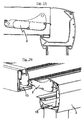
- the water collected by these channels opens up, as we can appreciate on the Figure 2B on a channel constituted by an extension 15 of the front beam 3.
- the extension of the front beam 3 comprises drip holes 16 arranged to coincide with support beams 17 of the front beam 3, as can be appreciated from FIG. figure 6 .
- These support beams may comprise internally optional PVC tubes T for drip, as can be seen on the figure 1 .
- the roof is designed so that the blades 2 are arranged with their upper and lower surfaces aligned when the bearing edges bear against the support tabs of the adjacent blades.
- the roof comprises joints between the front and rear beams 3 and 4 and the lateral beams 5, 6, so that it is possible to change the slope of the roof. These joints are similar to those described in the application ES200930286 of the plaintiff.
- the structure comprises union pieces 18 between the axes of the blade 2 and the lateral beams 5, 6.
- These union pieces 18 are made of plastic and comprise a U-shaped receptacle and provided with a narrowing in its upper part, so they form an interlocking ends of the axes by pressure. These parts are assembled in advance on the side beams, and therefore, for the installer, the assembly of the blades is easier because it has only to make a pressure attachment.
- the Figures 7 to 9 relate to a roof 1 'with rotating blades 2', comprising at least one front beam 3 'and a rear beam 4' intended to be arranged horizontally, at least two lateral beams 5 ', 6' intended to be arranged in a slope direction maximum and united by their ends to the front beams 3 'and posterior 4', several blades 2 'adjacent to each other and parallel to the front beams 3' and rear 4 ', each mounted on an axis of rotation 7' disposed between the side beams 5 ', 6', the blades 2 'being united on each side with a lower actuating profile 8' common to all the blades 2 'and parallel to the lateral beams 5', 6 ', the blades 2' being able to move between a maximum open position in which they have a maximum spacing between them and a closed position in which the front edge of each blade 2 'is supported on the rear edge of the adjacent blade 2'.
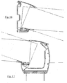
- the lower actuating section 8 'common to all the blades 2' comprises a wing 23 'extending laterally below the blades 2' and in a direction opposite to them and has a channel profile C1 'of collection of the water that may have flowed, which will eventually lead to the front profile 5 '.
- the lateral beams 5 ', 6' comprise a lower flange 24 'extending below and towards the blades, comprising the flange 23' of the lower actuating section 8 'common to all the blades 2' extending laterally below the blades 2 'and in a direction opposite to them and provided with an outer lower seal 16' intended to be in contact with the upper surface 24 'of the lower wing, so that the bumps are avoided when arriving at the maximum open position.
- the lateral beams 5 ', 6' comprise an upper lateral end groove S ', and in which the joint section 13' common of the upper ends of the blades 2 'comprises a wing 25' extending laterally over the 2 'and in opposite direction thereto and provided with an outer upper seal 17', so that in the closed position this outer upper seal 17 'presses the bottom of the groove upper lateral end S '.
- union pieces 18 ' between the axes of the blade 2' and the lateral beams 5 ', 6'.
- support beams 17 'of the front beam comprise in their interior drip tubes T'.
- the roof comprises joints between the front and rear beams 3 'and 4'. lateral beams 5 ', 6', so that it is possible to modify the slope of the roof. These joints are similar to those described in the patent ES200930286 of the plaintiff.
- the lower actuating section 8 ' is connected to a rod 9', in turn attached to a rotary lever 10 'actuated by a tubular motor M' housed in the rear section 4 '.
Landscapes
- Engineering & Computer Science (AREA)
- Architecture (AREA)
- Civil Engineering (AREA)
- Structural Engineering (AREA)
- Physics & Mathematics (AREA)
- Electromagnetism (AREA)
- Specific Sealing Or Ventilating Devices For Doors And Windows (AREA)
- Roof Covering Using Slabs Or Stiff Sheets (AREA)
- Turbine Rotor Nozzle Sealing (AREA)
Claims (12)
- Dachstruktur (1) mit drehbaren Lamellen (2), umfassend mindestens einen vorderen Träger (3) und einen hinteren Träger (4), welche vorgesehen sind, horizontal angeordnet zu sein, mindestens zwei Längsträger (5, 6), welche vorgesehen sind, entlang einer Richtung maximaler Neigung angeordnet und an ihren Enden mit dem vorderen Träger (3) und dem hinteren Träger (4) verbunden zu sein, eine Vielzahl von zueinander benachbarter und zu dem vorderen Träger (3) und dem hinteren Träger (4) paralleler Lamellen (2), welche jeweils auf einer Drehachse (7) montiert sind, die zwischen den Längsträgern (5, 6) angeordnet ist, wobei die Lamellen (2) mit einem für alle Lamellen (2) gemeinsamen und zu den Längsträgern parallelen (5, 6) Betätigungsprofil (8) verbunden sind, wobei die Lamellen (2) zwischen einer maximalen Öffnungsstellung, in welcher sie einen maximalen Abstand voneinander aufweisen, und einer Schließstellung, in welcher sich die Vorderkante einer jeden Lamelle (2) an der Hinterkante der angrenzenden Lamelle (2) abstützt, bewegbar sind, wobei die Drehachsen (7) in der maximalen Öffnungsposition an dem unteren Ende der Lamellen (2) angeordnet sind, und die Verbindungsstellen zwischen den Lamellen (2) und dem Profil (8) am anderen Ende der Lamellen (2) angeordnet sind, so dass es möglich ist, eine hohe Dichtigkeit dank der Anordnung von seitlichen Anlagedichtungen unterhalb der unteren Enden der Lamellen (2) zu erhalten, dadurch gekennzeichnet, dass die Dachstruktur Verbindungsteile (18) zwischen den Achsen der Lamellen (2) und den Längsträgern (5, 6) umfasst, wobei die Verbindungsteile (18) aus Kunststoff bestehen und eine U-förmige und mit einer Verengung im oberen Teil versehene Aufnahme aufweisen, so dass sie eine Einlassung der Enden der Achsen durch Druck bilden.
- Dachstruktur nach Anspruch 1, wobei das Profil (8) mit einer Stange (9) verbunden ist, welche ihrerseits an einem Drehhebel (10) angebracht ist, welcher durch einen in dem hinteren Träger (4) angeordneten Rohrmotor (M) angetrieben wird.
- Dachstruktur nach Anspruch 1, wobei die Längsträger (5, 6) Vorsprünge (13, 14) aufweisen, welche sich unter den Enden der Lamellen in Form von Kanälen zur Samznlung von Wasser erstrecken.
- Dachstruktur nach Anspruch 3, wobei die Vorsprünge (13, 14) Kanäle zur Sammlung von Wasser bilden, welche in einem durch einen Vorsprung (15) des vorderen Träger (3) gebildeten Kanal münden.
- Dachstruktur nach Anspruch 4, wobei der Vorsprung des vorderen Trägers (3) Tropflöchern (16) aufweist, welche derart angeordnet sind, dass sie mit Stützpfosten (17) des vorderen Trägers (3) zusammentreffen.
- Dachstruktur nach einem der vorhergehenden Ansprüche, umfassend Stützpfosten (17) des vorderen Trägers, welche vorzugsweise in ihrem Inneren Tropfrohre (T) aufweisen.
- Dachstruktur nach einem der vorhergehenden Ansprüche, wobei die Lamellen (2) ein Profil aufweisen, das, wenn sich die Lamellen (2) in ihrer Schließposition befinden, aufweist:- eine nach oben ausgerichtete Stützkante (11) an seinem hinteren Ende;- eine Stützzunge (12) an seinem vorderen Ende;so dass sich in der Schließstellung die Stützkante (11) an der Stützzunge (12) abstützt.
- Dachstruktur nach Anspruch 7, wobei alle Lamellen (2) mit ihrer Ober- und Unterseite fluchtend angeordnet sind, wenn sich die Stützkante auf den Stützzungen der benachbarten Lamellen abstützen.
- Dachstruktur nach einem der vorhergehenden Ansprüche, wobei die vordere und die hintere Abschiusslamelle sich auf entsprechenden an den Enden befestigten Elementen abstützen.
- Dachstruktur nach Anspruch 3, wobei die Stützkanten eine flexible Dichtung umfassen.
- Dachstruktur nach einem der vorhergehenden Ansprüche; umfassend einen zusätzlichen Längsträger, und zwischen dem zusätzlichen Längsträger und dem benachbarten Träger angeordnete zusätzliche Lamellen.
- Dachstruktur nach einem der vorhergehenden Ansprüche, mit Gelenken zwischen dem vorderen Träger (3) und dem hinteren Träger (4) und den Längsträgern (5, 6).
Applications Claiming Priority (2)
| Application Number | Priority Date | Filing Date | Title |
|---|---|---|---|
| ES201330367U ES1078998Y (es) | 2013-03-27 | 2013-03-27 | Cubierta con lamas abatibles con viga anterior y viga posterior |
| ES201330363U ES1079012Y (es) | 2013-03-27 | 2013-03-27 | Cubierta con lamas abatibles |
Publications (3)
| Publication Number | Publication Date |
|---|---|
| EP2803778A2 EP2803778A2 (de) | 2014-11-19 |
| EP2803778A3 EP2803778A3 (de) | 2014-12-10 |
| EP2803778B1 true EP2803778B1 (de) | 2016-05-25 |
Family
ID=49759009
Family Applications (1)
| Application Number | Title | Priority Date | Filing Date |
|---|---|---|---|
| EP13194937.2A Active EP2803778B1 (de) | 2013-03-27 | 2013-11-28 | Dach mit drehbaren Lamellen |
Country Status (2)
| Country | Link |
|---|---|
| EP (1) | EP2803778B1 (de) |
| ES (1) | ES2580502T3 (de) |
Cited By (2)
| Publication number | Priority date | Publication date | Assignee | Title |
|---|---|---|---|---|
| CN107476508A (zh) * | 2017-08-11 | 2017-12-15 | 北京江河幕墙系统工程有限公司 | 一种智能遮阳格栅系统 |
| IT202300019770A1 (it) * | 2023-09-26 | 2025-03-26 | Brianzatende Srl | Struttura di copertura |
Families Citing this family (10)
| Publication number | Priority date | Publication date | Assignee | Title |
|---|---|---|---|---|
| BE1024225B1 (nl) * | 2016-05-19 | 2017-12-18 | Renson Sunprotection Screens Nv | Lamellendak en werkwijze voor het aanpassen van een lamellendak |
| DE102016117774A1 (de) * | 2016-09-21 | 2018-03-22 | Jürgen Grimmeisen | Lamellendesign |
| ES1177733Y (es) * | 2017-02-15 | 2017-05-25 | Producciones Mitjavila Sau | Pérgola provista de lamas abatibles |
| US9822528B1 (en) * | 2017-03-23 | 2017-11-21 | Everlast Climbing Industries, Inc. | Bicycle shelter assembly |
| EP3444412B1 (de) * | 2017-08-14 | 2022-11-23 | weinor GmbH & Co. KG | Terrassendach mit feststehenden dachelementen und bewegbaren lamellen |
| GR1009514B (el) * | 2018-03-29 | 2019-04-24 | Cft Carbon Fiber Technologies Private Company | Συστημα σκιασης με κρυφο μηχανισμο περιστροφης περσιδων |
| EP3736390B1 (de) * | 2019-05-07 | 2022-02-23 | weinor GmbH & Co. KG | Lamellendach mit reibelement |
| CN111827732A (zh) * | 2020-08-17 | 2020-10-27 | 常州阿诺克邦遮阳材料有限公司 | 一种用于露台、庭院的皮带传动的伸缩生态凉亭 |
| ES2943516B2 (es) * | 2021-12-13 | 2024-07-22 | Luxe Perfil S L U | Dispositivo de seguridad estructural para cerramientos horizontales de lamas moviles |
| BE1030817B1 (nl) * | 2022-08-26 | 2024-03-25 | Brustor | Terrasoverkapping |
Family Cites Families (7)
| Publication number | Priority date | Publication date | Assignee | Title |
|---|---|---|---|---|
| IT8447774A0 (it) * | 1984-02-29 | 1984-02-29 | Gigli Mario | Tetto aerato a griglia parasole e pioggia |
| DE3640376A1 (de) * | 1986-11-26 | 1988-06-01 | Dietrich Weikert | Jalousieanordnung |
| ES2073954B1 (es) * | 1991-10-17 | 1996-03-01 | Tech Movil Espana S A | Techo graduable y sistema de accionamiento del mismo. |
| FR2701977B1 (fr) * | 1993-02-26 | 1995-04-14 | Christian Manenc | Système de toiture ouvrante, notamment pour véranda. |
| JPH06257355A (ja) * | 1993-03-04 | 1994-09-13 | Toshiyasu Suzuki | 建築用ルーバー装置 |
| AU2007237309A1 (en) * | 2006-12-05 | 2008-06-19 | Stratco (Australia) Pty Limited | An improved louvred roofing system and components |
| FR2947845B1 (fr) * | 2009-07-09 | 2011-10-07 | Biossun | Installation a lames orientables formant un toit de protection s'ouvrant et se fermant |
-
2013
- 2013-11-28 EP EP13194937.2A patent/EP2803778B1/de active Active
- 2013-11-28 ES ES13194937.2T patent/ES2580502T3/es active Active
Cited By (3)
| Publication number | Priority date | Publication date | Assignee | Title |
|---|---|---|---|---|
| CN107476508A (zh) * | 2017-08-11 | 2017-12-15 | 北京江河幕墙系统工程有限公司 | 一种智能遮阳格栅系统 |
| CN107476508B (zh) * | 2017-08-11 | 2019-08-20 | 北京江河幕墙系统工程有限公司 | 一种智能遮阳格栅系统 |
| IT202300019770A1 (it) * | 2023-09-26 | 2025-03-26 | Brianzatende Srl | Struttura di copertura |
Also Published As
| Publication number | Publication date |
|---|---|
| ES2580502T3 (es) | 2016-08-24 |
| EP2803778A2 (de) | 2014-11-19 |
| EP2803778A3 (de) | 2014-12-10 |
Similar Documents
| Publication | Publication Date | Title |
|---|---|---|
| EP2803778B1 (de) | Dach mit drehbaren Lamellen | |
| EP3554926B1 (de) | Spoiler für kraftfahrzeug mit beweglichen kanälen | |
| EP0956990B1 (de) | Faltdach in drei Teilen für Cabriofahrzeug | |
| EP2976957B1 (de) | Schutzhelm mit beweglichem kieferschild mit automatischem displayerfassungsmechanismus | |
| WO2011045092A1 (fr) | Dispositif d'obturation d'une baie ménagée dans le toit d'un véhicule automobile, équipé d'une évacuation d'eau vers l'extérieur | |
| FR2947845A1 (fr) | Installation a lames orientables formant un toit de protection s'ouvrant et se fermant | |
| EP1307621B1 (de) | Belüftetes lamellendach | |
| FR2845038A1 (fr) | Deflecteur en toile pour toit ouvrant de vehicule automobile et systeme de deflecteur escamotable associe | |
| EP3767049B1 (de) | Pergola beinhaltend eine tragende struktur und ein faltbares beschattungselement | |
| EP2651700B1 (de) | Vorderteil eines fahrzeuges, insbesondere eines kraftfahrzeuges, mit verbesserter sicherheit im falle eines fussgänger-aufpralls | |
| EP1375222B1 (de) | Fahrzeug mit einer verschiebbaren Sonnenblendeeinrichtung | |
| EP2598357B1 (de) | Dachintegrierte verriegelungs- und öffnungsvorrichtung eines kraftfahrzeuges mit halboffener verriegelungsposition | |
| FR3012107A1 (fr) | Structure avant de vehicule automobile equipee d'un spoiler mobile dispose sous le bouclier | |
| EP0659357A1 (de) | Schischuh | |
| EP3301240A1 (de) | Demontierbarer pergola-satz | |
| FR2514816A1 (fr) | Volet roulant hermetique | |
| FR3012084A1 (fr) | Deflecteur de vent pour une ouverture de toit d'un vehicule automobile | |
| FR3078089A1 (fr) | Protection solaire | |
| EP1782987A2 (de) | Wasserablaufeinrichtung für Dachteile eines KFZ-Faltverdecks | |
| FR3062368A1 (fr) | Vehicule comportant un conduit d’evacuation d’air du passage de roue | |
| FR2862321A1 (fr) | Lame de deneigement en v a ouverture fixe | |
| WO2011018570A2 (fr) | Partie avant de vehicule automobile. | |
| FR2499008A1 (fr) | Essuie-glace comportant un bras d'essuie-glace soumis a l'action d'un ressort en compression | |
| EP1717081A1 (de) | Windabweiser | |
| EP2103467A1 (de) | Öffenbares Verdeck |
Legal Events
| Date | Code | Title | Description |
|---|---|---|---|
| PUAL | Search report despatched |
Free format text: ORIGINAL CODE: 0009013 |
|
| PUAI | Public reference made under article 153(3) epc to a published international application that has entered the european phase |
Free format text: ORIGINAL CODE: 0009012 |
|
| 17P | Request for examination filed |
Effective date: 20131128 |
|
| AK | Designated contracting states |
Kind code of ref document: A2 Designated state(s): AL AT BE BG CH CY CZ DE DK EE ES FI FR GB GR HR HU IE IS IT LI LT LU LV MC MK MT NL NO PL PT RO RS SE SI SK SM TR |
|
| AX | Request for extension of the european patent |
Extension state: BA ME |
|
| AK | Designated contracting states |
Kind code of ref document: A3 Designated state(s): AL AT BE BG CH CY CZ DE DK EE ES FI FR GB GR HR HU IE IS IT LI LT LU LV MC MK MT NL NO PL PT RO RS SE SI SK SM TR |
|
| AX | Request for extension of the european patent |
Extension state: BA ME |
|
| RIC1 | Information provided on ipc code assigned before grant |
Ipc: E04B 7/16 20060101AFI20141104BHEP |
|
| R17P | Request for examination filed (corrected) |
Effective date: 20150610 |
|
| RBV | Designated contracting states (corrected) |
Designated state(s): AL AT BE BG CH CY CZ DE DK EE ES FI FR GB GR HR HU IE IS IT LI LT LU LV MC MK MT NL NO PL PT RO RS SE SI SK SM TR |
|
| GRAP | Despatch of communication of intention to grant a patent |
Free format text: ORIGINAL CODE: EPIDOSNIGR1 |
|
| INTG | Intention to grant announced |
Effective date: 20151208 |
|
| GRAS | Grant fee paid |
Free format text: ORIGINAL CODE: EPIDOSNIGR3 |
|
| GRAA | (expected) grant |
Free format text: ORIGINAL CODE: 0009210 |
|
| AK | Designated contracting states |
Kind code of ref document: B1 Designated state(s): AL AT BE BG CH CY CZ DE DK EE ES FI FR GB GR HR HU IE IS IT LI LT LU LV MC MK MT NL NO PL PT RO RS SE SI SK SM TR |
|
| REG | Reference to a national code |
Ref country code: GB Ref legal event code: FG4D Free format text: NOT ENGLISH |
|
| REG | Reference to a national code |
Ref country code: CH Ref legal event code: EP |
|
| REG | Reference to a national code |
Ref country code: IE Ref legal event code: FG4D Free format text: LANGUAGE OF EP DOCUMENT: FRENCH Ref country code: AT Ref legal event code: REF Ref document number: 802466 Country of ref document: AT Kind code of ref document: T Effective date: 20160615 |
|
| REG | Reference to a national code |
Ref country code: DE Ref legal event code: R096 Ref document number: 602013007871 Country of ref document: DE |
|
| REG | Reference to a national code |
Ref country code: ES Ref legal event code: FG2A Ref document number: 2580502 Country of ref document: ES Kind code of ref document: T3 Effective date: 20160824 |
|
| REG | Reference to a national code |
Ref country code: LT Ref legal event code: MG4D |
|
| REG | Reference to a national code |
Ref country code: NL Ref legal event code: MP Effective date: 20160525 |
|
| PG25 | Lapsed in a contracting state [announced via postgrant information from national office to epo] |
Ref country code: NO Free format text: LAPSE BECAUSE OF FAILURE TO SUBMIT A TRANSLATION OF THE DESCRIPTION OR TO PAY THE FEE WITHIN THE PRESCRIBED TIME-LIMIT Effective date: 20160825 Ref country code: NL Free format text: LAPSE BECAUSE OF FAILURE TO SUBMIT A TRANSLATION OF THE DESCRIPTION OR TO PAY THE FEE WITHIN THE PRESCRIBED TIME-LIMIT Effective date: 20160525 Ref country code: FI Free format text: LAPSE BECAUSE OF FAILURE TO SUBMIT A TRANSLATION OF THE DESCRIPTION OR TO PAY THE FEE WITHIN THE PRESCRIBED TIME-LIMIT Effective date: 20160525 Ref country code: LT Free format text: LAPSE BECAUSE OF FAILURE TO SUBMIT A TRANSLATION OF THE DESCRIPTION OR TO PAY THE FEE WITHIN THE PRESCRIBED TIME-LIMIT Effective date: 20160525 |
|
| REG | Reference to a national code |
Ref country code: FR Ref legal event code: PLFP Year of fee payment: 4 |
|
| REG | Reference to a national code |
Ref country code: AT Ref legal event code: MK05 Ref document number: 802466 Country of ref document: AT Kind code of ref document: T Effective date: 20160525 |
|
| PG25 | Lapsed in a contracting state [announced via postgrant information from national office to epo] |
Ref country code: RS Free format text: LAPSE BECAUSE OF FAILURE TO SUBMIT A TRANSLATION OF THE DESCRIPTION OR TO PAY THE FEE WITHIN THE PRESCRIBED TIME-LIMIT Effective date: 20160525 Ref country code: SE Free format text: LAPSE BECAUSE OF FAILURE TO SUBMIT A TRANSLATION OF THE DESCRIPTION OR TO PAY THE FEE WITHIN THE PRESCRIBED TIME-LIMIT Effective date: 20160525 Ref country code: LV Free format text: LAPSE BECAUSE OF FAILURE TO SUBMIT A TRANSLATION OF THE DESCRIPTION OR TO PAY THE FEE WITHIN THE PRESCRIBED TIME-LIMIT Effective date: 20160525 Ref country code: PT Free format text: LAPSE BECAUSE OF FAILURE TO SUBMIT A TRANSLATION OF THE DESCRIPTION OR TO PAY THE FEE WITHIN THE PRESCRIBED TIME-LIMIT Effective date: 20160926 Ref country code: GR Free format text: LAPSE BECAUSE OF FAILURE TO SUBMIT A TRANSLATION OF THE DESCRIPTION OR TO PAY THE FEE WITHIN THE PRESCRIBED TIME-LIMIT Effective date: 20160826 |
|
| PG25 | Lapsed in a contracting state [announced via postgrant information from national office to epo] |
Ref country code: IT Free format text: LAPSE BECAUSE OF FAILURE TO SUBMIT A TRANSLATION OF THE DESCRIPTION OR TO PAY THE FEE WITHIN THE PRESCRIBED TIME-LIMIT Effective date: 20160525 |
|
| PG25 | Lapsed in a contracting state [announced via postgrant information from national office to epo] |
Ref country code: EE Free format text: LAPSE BECAUSE OF FAILURE TO SUBMIT A TRANSLATION OF THE DESCRIPTION OR TO PAY THE FEE WITHIN THE PRESCRIBED TIME-LIMIT Effective date: 20160525 Ref country code: CZ Free format text: LAPSE BECAUSE OF FAILURE TO SUBMIT A TRANSLATION OF THE DESCRIPTION OR TO PAY THE FEE WITHIN THE PRESCRIBED TIME-LIMIT Effective date: 20160525 Ref country code: SK Free format text: LAPSE BECAUSE OF FAILURE TO SUBMIT A TRANSLATION OF THE DESCRIPTION OR TO PAY THE FEE WITHIN THE PRESCRIBED TIME-LIMIT Effective date: 20160525 Ref country code: DK Free format text: LAPSE BECAUSE OF FAILURE TO SUBMIT A TRANSLATION OF THE DESCRIPTION OR TO PAY THE FEE WITHIN THE PRESCRIBED TIME-LIMIT Effective date: 20160525 Ref country code: RO Free format text: LAPSE BECAUSE OF FAILURE TO SUBMIT A TRANSLATION OF THE DESCRIPTION OR TO PAY THE FEE WITHIN THE PRESCRIBED TIME-LIMIT Effective date: 20160525 |
|
| PG25 | Lapsed in a contracting state [announced via postgrant information from national office to epo] |
Ref country code: PL Free format text: LAPSE BECAUSE OF FAILURE TO SUBMIT A TRANSLATION OF THE DESCRIPTION OR TO PAY THE FEE WITHIN THE PRESCRIBED TIME-LIMIT Effective date: 20160525 Ref country code: SM Free format text: LAPSE BECAUSE OF FAILURE TO SUBMIT A TRANSLATION OF THE DESCRIPTION OR TO PAY THE FEE WITHIN THE PRESCRIBED TIME-LIMIT Effective date: 20160525 Ref country code: AT Free format text: LAPSE BECAUSE OF FAILURE TO SUBMIT A TRANSLATION OF THE DESCRIPTION OR TO PAY THE FEE WITHIN THE PRESCRIBED TIME-LIMIT Effective date: 20160525 Ref country code: BE Free format text: LAPSE BECAUSE OF NON-PAYMENT OF DUE FEES Effective date: 20161130 |
|
| REG | Reference to a national code |
Ref country code: DE Ref legal event code: R097 Ref document number: 602013007871 Country of ref document: DE |
|
| PLBE | No opposition filed within time limit |
Free format text: ORIGINAL CODE: 0009261 |
|
| STAA | Information on the status of an ep patent application or granted ep patent |
Free format text: STATUS: NO OPPOSITION FILED WITHIN TIME LIMIT |
|
| 26N | No opposition filed |
Effective date: 20170228 |
|
| PG25 | Lapsed in a contracting state [announced via postgrant information from national office to epo] |
Ref country code: SI Free format text: LAPSE BECAUSE OF FAILURE TO SUBMIT A TRANSLATION OF THE DESCRIPTION OR TO PAY THE FEE WITHIN THE PRESCRIBED TIME-LIMIT Effective date: 20160525 |
|
| REG | Reference to a national code |
Ref country code: DE Ref legal event code: R119 Ref document number: 602013007871 Country of ref document: DE |
|
| REG | Reference to a national code |
Ref country code: CH Ref legal event code: PL |
|
| PG25 | Lapsed in a contracting state [announced via postgrant information from national office to epo] |
Ref country code: CH Free format text: LAPSE BECAUSE OF NON-PAYMENT OF DUE FEES Effective date: 20161130 Ref country code: LI Free format text: LAPSE BECAUSE OF NON-PAYMENT OF DUE FEES Effective date: 20161130 |
|
| REG | Reference to a national code |
Ref country code: IE Ref legal event code: MM4A |
|
| PG25 | Lapsed in a contracting state [announced via postgrant information from national office to epo] |
Ref country code: LU Free format text: LAPSE BECAUSE OF NON-PAYMENT OF DUE FEES Effective date: 20161130 |
|
| PG25 | Lapsed in a contracting state [announced via postgrant information from national office to epo] |
Ref country code: IE Free format text: LAPSE BECAUSE OF NON-PAYMENT OF DUE FEES Effective date: 20161128 Ref country code: DE Free format text: LAPSE BECAUSE OF NON-PAYMENT OF DUE FEES Effective date: 20170601 |
|
| REG | Reference to a national code |
Ref country code: FR Ref legal event code: PLFP Year of fee payment: 5 |
|
| REG | Reference to a national code |
Ref country code: BE Ref legal event code: MM Effective date: 20161130 |
|
| PG25 | Lapsed in a contracting state [announced via postgrant information from national office to epo] |
Ref country code: HU Free format text: LAPSE BECAUSE OF FAILURE TO SUBMIT A TRANSLATION OF THE DESCRIPTION OR TO PAY THE FEE WITHIN THE PRESCRIBED TIME-LIMIT; INVALID AB INITIO Effective date: 20131128 |
|
| PG25 | Lapsed in a contracting state [announced via postgrant information from national office to epo] |
Ref country code: CY Free format text: LAPSE BECAUSE OF FAILURE TO SUBMIT A TRANSLATION OF THE DESCRIPTION OR TO PAY THE FEE WITHIN THE PRESCRIBED TIME-LIMIT Effective date: 20160525 Ref country code: HR Free format text: LAPSE BECAUSE OF FAILURE TO SUBMIT A TRANSLATION OF THE DESCRIPTION OR TO PAY THE FEE WITHIN THE PRESCRIBED TIME-LIMIT Effective date: 20160525 Ref country code: MC Free format text: LAPSE BECAUSE OF FAILURE TO SUBMIT A TRANSLATION OF THE DESCRIPTION OR TO PAY THE FEE WITHIN THE PRESCRIBED TIME-LIMIT Effective date: 20160525 Ref country code: IS Free format text: LAPSE BECAUSE OF FAILURE TO SUBMIT A TRANSLATION OF THE DESCRIPTION OR TO PAY THE FEE WITHIN THE PRESCRIBED TIME-LIMIT Effective date: 20160525 Ref country code: MK Free format text: LAPSE BECAUSE OF FAILURE TO SUBMIT A TRANSLATION OF THE DESCRIPTION OR TO PAY THE FEE WITHIN THE PRESCRIBED TIME-LIMIT Effective date: 20160525 |
|
| GBPC | Gb: european patent ceased through non-payment of renewal fee |
Effective date: 20171128 |
|
| PG25 | Lapsed in a contracting state [announced via postgrant information from national office to epo] |
Ref country code: BG Free format text: LAPSE BECAUSE OF FAILURE TO SUBMIT A TRANSLATION OF THE DESCRIPTION OR TO PAY THE FEE WITHIN THE PRESCRIBED TIME-LIMIT Effective date: 20160525 |
|
| PG25 | Lapsed in a contracting state [announced via postgrant information from national office to epo] |
Ref country code: MT Free format text: LAPSE BECAUSE OF FAILURE TO SUBMIT A TRANSLATION OF THE DESCRIPTION OR TO PAY THE FEE WITHIN THE PRESCRIBED TIME-LIMIT Effective date: 20160525 |
|
| PG25 | Lapsed in a contracting state [announced via postgrant information from national office to epo] |
Ref country code: TR Free format text: LAPSE BECAUSE OF FAILURE TO SUBMIT A TRANSLATION OF THE DESCRIPTION OR TO PAY THE FEE WITHIN THE PRESCRIBED TIME-LIMIT Effective date: 20160525 Ref country code: AL Free format text: LAPSE BECAUSE OF FAILURE TO SUBMIT A TRANSLATION OF THE DESCRIPTION OR TO PAY THE FEE WITHIN THE PRESCRIBED TIME-LIMIT Effective date: 20160525 |
|
| REG | Reference to a national code |
Ref country code: FR Ref legal event code: PLFP Year of fee payment: 6 |
|
| PG25 | Lapsed in a contracting state [announced via postgrant information from national office to epo] |
Ref country code: GB Free format text: LAPSE BECAUSE OF NON-PAYMENT OF DUE FEES Effective date: 20171128 |
|
| PGFP | Annual fee paid to national office [announced via postgrant information from national office to epo] |
Ref country code: FR Payment date: 20251118 Year of fee payment: 13 |
|
| PGFP | Annual fee paid to national office [announced via postgrant information from national office to epo] |
Ref country code: ES Payment date: 20251201 Year of fee payment: 13 |