EP2803586B1 - Ausschwenkbares Vordach einer Fluggasttreppe oder Fluggastbrücke - Google Patents
Ausschwenkbares Vordach einer Fluggasttreppe oder Fluggastbrücke Download PDFInfo
- Publication number
- EP2803586B1 EP2803586B1 EP13002635.4A EP13002635A EP2803586B1 EP 2803586 B1 EP2803586 B1 EP 2803586B1 EP 13002635 A EP13002635 A EP 13002635A EP 2803586 B1 EP2803586 B1 EP 2803586B1
- Authority
- EP
- European Patent Office
- Prior art keywords
- air passenger
- pivotable
- end member
- canopy roof
- stair
- Prior art date
- Legal status (The legal status is an assumption and is not a legal conclusion. Google has not performed a legal analysis and makes no representation as to the accuracy of the status listed.)
- Not-in-force
Links
- 230000001419 dependent effect Effects 0.000 claims description 2
- 229920001971 elastomer Polymers 0.000 claims description 2
- 239000000806 elastomer Substances 0.000 claims description 2
- 238000005096 rolling process Methods 0.000 claims 1
- 210000000245 forearm Anatomy 0.000 description 9
- 238000010276 construction Methods 0.000 description 2
- 239000006260 foam Substances 0.000 description 1
- 238000009434 installation Methods 0.000 description 1
- 239000000463 material Substances 0.000 description 1
- 230000007704 transition Effects 0.000 description 1
- 238000004804 winding Methods 0.000 description 1
Images


Classifications
-
- B—PERFORMING OPERATIONS; TRANSPORTING
- B64—AIRCRAFT; AVIATION; COSMONAUTICS
- B64F—GROUND OR AIRCRAFT-CARRIER-DECK INSTALLATIONS SPECIALLY ADAPTED FOR USE IN CONNECTION WITH AIRCRAFT; DESIGNING, MANUFACTURING, ASSEMBLING, CLEANING, MAINTAINING OR REPAIRING AIRCRAFT, NOT OTHERWISE PROVIDED FOR; HANDLING, TRANSPORTING, TESTING OR INSPECTING AIRCRAFT COMPONENTS, NOT OTHERWISE PROVIDED FOR
- B64F1/00—Ground or aircraft-carrier-deck installations
- B64F1/30—Ground or aircraft-carrier-deck installations for embarking or disembarking passengers
- B64F1/305—Bridges extending between terminal building and aircraft, e.g. telescopic, vertically adjustable
- B64F1/3055—Bridges extending between terminal building and aircraft, e.g. telescopic, vertically adjustable with hinged head interface between aircraft and passenger bridge
Definitions
- the invention relates to a swing-out canopy of a passenger stairway or passenger boarding bridge according to the preamble of claim 1.
- a swing-out canopy of a passenger staircase or passenger boarding bridge of the type mentioned is from the DE 10 2004 016 272 B4 known.
- the construction of this canopy has proven extremely successful and is widely used.
- this may be due to the fact that the aircraft fuselage is strongly contoured in this area of the access, or because of the fact that, in particular, in the case of large canopies due to the stable design of the articulated arms the inherent elasticity of the canopy and here in particular the articulated arms is only minimal. This means that the deformation is not sufficient to ensure a full-surface concern of the flexible frame with the bumper.
- a canopy of a passenger bridge known, the canopy at its free end has a frame which is provided with a circumferential bumpers.
- a telescopic articulated arm is provided on each side.
- This telescopic articulated arm has at its end associated with the flexible frame with the bumper an end member, said end member is connected by a double joint with the free end of the telescoping arm. Through this double joint a lateral swinging of the end member is achieved.
- the arm is retracted by an actuator.
- the object underlying the invention is therefore to ensure that the bumper with the flexible frame over the entire surface rests on the fuselage.
- the canopy of the passenger boarding stairway or passenger bridge has an actuating device for swiveling out, wherein the actuating device comprises a traction mechanism at least for the one first articulated arm.
- a roller is provided for the traction means.
- the end member of the at least one first articulated arm can be laterally swung out by a pivot joint.
- a lateral swinging means in this case that the end member is swung in the direction of the width of the flexible frame, and in particular can be swung out in the direction of the inside of the canopy.
- the end member of the at least one first articulated arm pivots slightly inward, and thus to a full-surface Concerns concern of the flexible frame on the outer skin of the aircraft.
- the traction means is articulated laterally on the end member of the articulated arm, that is, on the side to which the end member is not pivoted. That is, the articulation of the traction means is eccentric. This has the consequence that the arrangement of the traction means on the end member on the outside of the end member when retracting the straight positioning of the end member is supported.
- the upper arm with the lower arm in which a first articulated arm by a hinge joint with in Installation state horizontal hinge axis is connected wherein the hinge axis of the pivot joint for the laterally swingable or exhibitable end member perpendicular to the hinge axis between the upper arm and lower arm.
- the end member is connected by an intermediate member with the forearm.
- the first articulated arm consists of a total of four elements, namely an upper arm, an articulated lower arm, on which in turn an intermediate member is arranged, which is preferably angled in the direction of the pivot plane of the articulated arm relative to the forearm, as well as the end member, the is laterally pivotally receivable by a pivot joint through the intermediate member.
- the end member is pivotable against a spring force out of the plane with the forearm. This ensures that when retracting the canopy is ensured in each case that the end member is in a plane with the first articulated arm.
- the end member is laterally pivotable in one direction only, namely laterally in the direction of the inside of the canopy.
- connection between the intermediate member and the end member is formed as in itself laterally movable connection, wherein the intermediate member has a lug which is received with lateral play by the end member. That is, the approach of the intermediate member superimposed in the hollow profile of the end member with a lateral clearance to allow the lateral Aus sokeit of the end member relative to the intermediate member. Between the approach and designed as a hollow profile end member arranged an elastomeric block against which the end member is resiliently pivotable. That is, the distance between the approach of the intermediate member and the inner wall of the end member determines inter alia the degree of deflection of the end member.
- the second articulated arm by a traction means, for. B. a rope or a belt with the portal frame in connection.
- each roller on the portal frame is assigned a roller for winding and unwinding of the traction means, for example a belt or a rope, the two rollers being connected by a shaft to a drive, for example a tubular motor.
- the actuating device comprises at least one drive member for the at least one first articulated arm, which is designed in particular as a gas pressure spring.
- the canopy 1 of the passenger stairway or passenger bridge 11 comprises a portal frame 2 and the flexible frame 3, the end of the bumper. 4 made of elastically yielding material, such. B. foam, absorbs. Between the portal frame on the one hand and the flexible frame 3 on the other hand, the bellows 5 is clamped.
- the bellows 5 is its contour as well as the flexible frame and the portal frame 2 formed in the manner of a U, and spans the total designated 10 transition bottom.
- the bellows In the bottom region of the two legs 5a of the bellows 5, the bellows has a plurality of successively arranged bellows eyelets 6, which are received by the guide rail 7, wherein the guide rail 7 ends on the one hand to the flexible frame and the other to the passenger stairway or passenger bridge 11 itself or the Portal frame is attached.
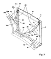
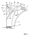
- the actuating device 20 can be seen, comprising the first articulated arm 30 and the second laterally spaced articulated arm 30a.
- Each of the two articulated arms 30, 30a is assigned a roller 41, 47 arranged on the portal frame 2 for a traction means 49.
- the two rollers 41, 47 are connected by the rotatable shaft 40, which via a drive, not shown, for. B. in the form of a tubular motor has connected.
- the actuating device further comprises two drive members 51, 55 for the first and second articulated arm 30, 30a, which are advantageously designed as gas pressure springs.
- the generally designated 30, 30a articulated arm is located in the region of each leg 5a of the bellows 5 in the ceiling area of the bellows on the portal frame, and includes the hinged to the portal frame connected upper arm 31, 31 a and the upper arm 31, 31 a also articulated Forearm 35, 35a.
- the lower arm and the upper arm are interconnected by a hinge joint 34, 34a, which has a horizontal hinge axis in the installed state.
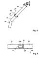
- the lower arm 35, 35a has the end member 36, 36a on the end, wherein the connection of the end member 36 of the first articulated arm 30 to the forearm of the representation according to Fig. 5 and Fig. 6 can be removed.
- the forearm 35 shows angled to the forearm and although angled in the plane of the articulated arm 30, the intermediate member 33.
- the intermediate member 33 has a projection 33a, which projects with lateral play in the form of a hollow profile end member 36. Furthermore, it can be seen that the end member 36 is pivotally connected by the pivot joint 37 with the projection 33 a.
- the end member 36 is pivotable relative to the intermediate member 33 out of the plane of the articulated arm 30, as seen in the view of Fig. 3 and Fig. 6 results.
- the end member 36 only in one direction, namely in the direction of arrow 60 (FIG. Fig.
- the intermediate member 33 is wedge-shaped (arrow 61) formed on the end member 36 facing end, so that in fact the end member 36 can pivot only in the direction of arrow 60 about the hinge axis of the pivot joint 37. That is, the higher end of the wedge-shaped end forms a stop for the end member.
- an elastomeric block 39 is an elastomeric block 39 as a possible spring element, so that the pivoting of the end member 36 in the direction of the arrow 60 against the force of the elastomeric pad 39, so that the end member 36 when retracting the canopy always returns to its original position.
- the end member 36 is connected to the roller 41 by a belt or a rope 49 in connection in such a way that the cable 49 is arranged laterally, that is eccentrically on the end member, as this is directly in the view of Fig. 3 results.
- the opposing articulated arm 30 does not have to have such an articulated design of the end member. Rather, this is provided only for the articulated arm in the region of the bow-side end of the aircraft in order to ensure a substantially stress-free engagement of the canopy on the fuselage.
Landscapes
- Engineering & Computer Science (AREA)
- Architecture (AREA)
- Civil Engineering (AREA)
- Structural Engineering (AREA)
- Mechanical Engineering (AREA)
- Aviation & Aerospace Engineering (AREA)
- Tents Or Canopies (AREA)
- Bridges Or Land Bridges (AREA)
- Power-Operated Mechanisms For Wings (AREA)
- Body Structure For Vehicles (AREA)
- Ladders (AREA)
Description
- Die Erfindung betrifft ein ausschwenkbares Vordach einer Fluggasttreppe oder Fluggastbrücke gemäß dem Oberbegriff des Anspruchs 1.
- Ein ausschwenkbares Vordach einer Fluggasttreppe oder Fluggastbrücke der eingangs genannten Art ist aus der
DE 10 2004 016 272 B4 bekannt. Die Konstruktion dieses Vordaches hat sich außerordentlich bewährt und ist vielfach im Einsatz. Jedoch hat sich herausgestellt, dass bei stark konturierten Flugzeugrümpfen, und hier insbesondere im Bereich des bugseitigen Zustiegs der flexible Rahmen mit welchem das Vordach an der Außenhaut des Flugzeugrumpfes anliegt, bugseitig also zum vorderen Ende des Flugzeugs zu nicht immer bündig an der Flugzeughülle anliegt. Dies kann zum einen daran liegen, wie bereits ausgeführt, dass der Flugzeugrumpf in diesem Bereich des Zugangs stark konturiert ist, oder auch daran, dass insbesondere bei großen Vordächern aufgrund der stabilen Gestaltung der Gelenkarme die Eigenelastizität des Vordaches und hier insbesondere der Gelenkarme nur minimal ist. Das heißt, dass die Verformung nicht ausreichend ist, um ein vollflächiges Anliegen des flexiblen Rahmens mit dem Bumper zu gewährleisten. - Aus der
US 4,120,067 ist ein Vordach einer Fluggastbrücke bekannt, wobei das Vordach an seinem freien Ende einen Rahmen aufweist, der mit einem umlaufenden Bumper versehen ist. Zur Ausstellung des Vordachs in Richtung auf die Außenhaut des Flugzeugs ist auf jeder Seite jeweils ein teleskopierbarer Gelenkarm vorgesehen. Dieser teleskopierbare Gelenkarm weist an seinem dem flexiblen Rahmen mit dem Bumper zugeordneten Ende ein Endglied auf, wobei dieses Endglied durch ein Doppelgelenk mit dem freien Ende des teleskopierbaren Armes in Verbindung steht. Durch dieses Doppelgelenk wird ein seitliches Ausschwenken des Endgliedes erreicht. Eingefahren wird der Arm durch einen Stellantrieb. - Aus der
EP 1867569 A2 ist ebenfalls das Vordach einer Fluggastbrücke oder -treppe bekannt, wobei auch hier zu beiden Seiten des Vordaches ein Gelenkarm vorgesehen ist, durch den das Vordach in Richtung auf die Außenhaut des Flugzeugs ausgestellt werden kann. Für den Antrieb des Gelenkarmes sind Kolbenzylinderantriebe vorgesehen. - Die der Erfindung zugrunde liegende Aufgabe besteht demzufolge darin, dafür zu sorgen, dass der Bumper mit dem flexiblen Rahmen vollflächig am Flugzeugrumpf anliegt.
- Die Lösung der Aufgabe erfolgt durch die Merkmale des kennzeichnenden Teils des Anspruchs 1 in Verbindung mit den Merkmalen des Oberbegriffs.
- Das Vordach der Fluggasttreppe oder Fluggastbrücke weist zum Ausschwenken eine Betätigungsvorrichtung auf, wobei die Betätigungsvorrichtung mindestens für den einen ersten Gelenkarm ein Zugmittel umfasst. Im Bereich des Portalrahmens ist eine Rolle für das Zugmittel vorgesehen. Das Endglied des mindestens einen ersten Gelenkarms ist durch ein Schwenkgelenk seitlich ausschwenkbar. Ein seitliches Ausschwenken bedeutet hierbei, dass das Endglied in Richtung der Breite des flexiblen Rahmens ausschwenkbar ist, und zwar insbesondere in Richtung auf die Innenseite des Vordaches ausschwenkbar ist. Das heißt, dass bei Anlegen des flexiblen Rahmens des ausschwenkbaren Vordaches an der Flugzeugaußenhaut im Moment des Auftreffens des flexiblen Rahmens im Bereich des Endgliedes auf die Außenhaut des Flugzeuges, sich das Endglied des mindestens einen ersten Gelenkarmes leicht nach innen verschwenkt, und insofern für ein vollflächiges Anliegen des flexiblen Rahmens an der Außenhaut des Flugzeugs sorgt. Durch das Verschwenken des Endgliedes nach innen wird ein im Wesentlichen spannungsfreies Anliegen des Vordaches am Flugzeugrumpf gewährleistet.
- Das Zugmittel ist seitlich am Endglied des Gelenkarmes angelenkt, also an der Seite zu der das Endglied nicht verschwenkt. Das heißt, die Anlenkung des Zugmittels erfolgt exzentrisch. Das hat zur Folge, dass durch die Anordnung des Zugmittels am Endglied an der Außenseite des Endgliedes beim Einfahren das Geradestellen des Endgliedes unterstützt wird.
- Vorteilhafte Merkmale und Ausgestaltungen der Erfindung sind den Unteransprüchen zu entnehmen. Im Folgenden wird der Aufbau des ersten Gelenkarms näher beschrieben.
- So ist insbesondere vorgesehen, dass der Oberarm mit dem Unterarm bei dem einen ersten Gelenkarm durch ein Scharniergelenk mit im Einbauzustand horizontaler Scharnierachse verbunden ist, wobei die Gelenkachse des Schwenkgelenkes für das seitlich ausschwenkbare oder ausstellbare Endglied senkrecht zur Scharnierachse zwischen Oberarm und Unterarm verläuft.
- Nach einem weiteren Merkmal der Erfindung ist das Endglied durch ein Zwischenglied mit dem Unterarm verbunden. Das heißt, dass der erste Gelenkarm aus insgesamt vier Elementen besteht, nämlich einem Oberarm, einem damit gelenkig verbundenen Unterarm, an dem wiederum ein Zwischenglied angeordnet ist, das vorzugsweise in Richtung der Schwenkebene des Gelenkarmes relativ zum Unterarm abgewinkelt ist, sowie dem Endglied, das durch ein Schwenkgelenk seitlich verschwenkbar durch das Zwischenglied aufnehmbar ist.
- Nach einem besonders vorteilhaften Merkmal ist das Endglied entgegen einer Federkraft aus der Ebene mit dem Unterarm verschwenkbar. Hierdurch wird bewirkt, dass beim Einfahren des Vordaches in jedem Fall sichergestellt ist, dass das Endglied sich in einer Ebene mit dem ersten Gelenkarm befindet.
- Weiterhin vorteilhaft ist, wenn sichergestellt ist, dass das Endglied seitlich, lediglich in einer Richtung verschwenkbar ist, nämlich seitlich in Richtung der Innenseite des Vordaches.
- Die Verbindung zwischen dem Zwischenglied und dem Endglied ist als in sich seitlich bewegliche Verbindung ausgebildet, wobei das Zwischenglied einen Ansatz aufweist, der mit seitlichem Spiel durch das Endglied aufgenommen ist. Das heißt, der Ansatz des Zwischengliedes lagert in dem Hohlprofil des Endglieds mit seitlichem Spiel, um die seitliche Ausstellbarkeit des Endgliedes relativ zum Zwischenglied zu ermöglichen. Zwischen dem Ansatz und dem als Hohlprofil ausgebildeten Endglied ist ein Elastomerbock angeordnet, gegen den das Endglied federnd nachgiebig verschwenkbar ist. Das heißt, der Abstand zwischen dem Ansatz des Zwischengliedes und der Innenwand des Endgliedes bestimmt unter anderem den Grad der Auslenkung des Endgliedes.
- Vorteilhaft steht auch der zweite Gelenkarm durch ein Zugmittel, z. B. ein Seil oder ein Gurt mit dem Portalrahmen in Verbindung.
- Im Einzelnen ist des Weiteren jedem Zugmittel am Portalrahmen eine Rolle zum Auf- und Abrollen des Zugmittels also beispielsweise einem Gurt oder einem Seil zugeordnet, wobei die beiden Rollen durch eine Welle mit einem Antrieb, beispielsweise einem Rohrmotor, verbunden sind.
- Zur Einleitung der Ausstellbewegung der Gelenkarme umfasst die Betätigungsvorrichtung mindestens ein Antriebsglied für den mindestens einen ersten Gelenkarm, das insbesondere als Gasdruckfeder ausgebildet ist.
- Anhand der Zeichnungen wird die Erfindung nachstehend beispielhaft näher erläutert.
- Fig. 1
- zeigt das Vordach der Fluggasttreppe oder Fluggastbrücke in einer perspektivischen Ansicht von oben;
- Fig. 2
- zeigt eine Seitenansicht des Vordaches gemäß
Fig. 1 im Schnitt; - Fig. 3
- zeigt eine Ansicht gemäß
Fig. 1 , wobei jedoch der Balg weggelassen ist; - Fig. 4
- zeigt eine Ansicht gemäß
Fig. 2 ebenfalls ohne einen Balg; - Fig. 5
- zeigt den Ausschnitt X aus
Fig. 4 in vergrößerter Darstellung ohne frontseitigem Rahmen; - Fig. 6
- zeigt einen Schnitt gemäß der Linie VI-VI aus
Fig. 5 . - Das Vordach 1 der Fluggasttreppe oder Fluggastbrücke 11 umfasst einen Portalrahmen 2 und den flexiblen Rahmen 3, der endseitig den Bumper 4 aus elastisch nachgiebigem Material, wie z. B. Schaumstoff, aufnimmt. Zwischen dem Portalrahmen einerseits und dem flexiblen Rahmen 3 andererseits ist der Faltenbalg 5 aufgespannt. Der Faltenbalg 5 ist seiner Kontur ebenso wie der flexible Rahmen und auch der Portalrahmen 2 nach Art eines U ausgebildet, und überspannt den insgesamt mit 10 bezeichneten Übergangsboden. Im Bodenbereich der beiden Schenkel 5a des Balges 5 besitzt der Balg mehrere hintereinander angeordnete Balgösen 6, die von der Führungsschiene 7 aufgenommen werden, wobei die Führungsschiene 7 endseitig zum einen an den flexiblen Rahmen und zum anderen an der Fluggasttreppe bzw. Fluggastbrücke 11 selbst oder dem Portalrahmen befestigt ist.
- Aus der Darstellung gemäß
Fig. 2 ist zum einen die Betätigungsvorrichtung 20 erkennbar, umfassend den ersten Gelenkarm 30 und den zweiten seitlich dazu beabstandeten Gelenkarm 30a. Den beiden Gelenkarmen 30, 30a ist jeweils eine am Portalrahmen 2 angeordnete Rolle 41, 47 für ein Zugmittel 49 zugeordnet. Die beiden Rollen 41, 47 sind durch die drehbare Welle 40, die über einen nicht dargestellten Antrieb z. B. in Form eines Rohrmotors verfügt, verbunden. Die Betätigungsvorrichtung umfasst darüber hinaus für den ersten und zweiten Gelenkarm 30, 30a jeweils zwei Antriebsglieder 51, 55, die vorteilhaft als Gasdruckfedern ausgebildet sind. Der insgesamt mit 30, 30a bezeichnete Gelenkarm ist im Bereich eines jeden Schenkels 5a des Faltenbalges 5 im Deckenbereich des Balges am Portalrahmen angeordnet, und umfasst den gelenkig mit dem Portalrahmen verbundenen Oberarm 31, 31 a und den am Oberarm 31, 31 a ebenfalls gelenkig angeordneten Unterarm 35, 35a. Der Unterarm und der Oberarm sind durch ein Scharniergelenk 34, 34a miteinander verbunden, das im Einbauzustand eine horizontale Scharnierachse aufweist. Der Unterarm 35, 35a weist endseitig das Endglied 36, 36a auf, wobei sich die Anbindung des Endgliedes 36 des ersten Gelenkarms 30 an dem Unterarm der Darstellung gemäßFig. 5 und Fig. 6 entnehmen lässt. Der Unterarm 35 zeigt abgewinkelt zum Unterarm und zwar in der Ebene des Gelenkarms 30 abgewinkelt, das Zwischenglied 33. Das Zwischenglied 33 besitzt einen Ansatz 33a, der mit seitlichem Spiel in das als Hohlprofil ausgebildete Endglied 36 ragt. Des Weiteren ist erkennbar, dass das Endglied 36 durch das Schwenkgelenk 37 mit dem Ansatz 33a schwenkbar verbunden ist. Das Endglied 36 ist relativ zu dem Zwischenglied 33 aus der Ebene des Gelenkarmes 30 verschwenkbar, wie sich dies in Anschauung vonFig. 3 undFig. 6 ergibt. Um nun zu gewährleisten, dass das Endglied 36 nur in eine Richtung, nämlich in Richtung des Pfeiles 60 (Fig. 6 ) ausschwenkbar ist, ist das Zwischenglied 33 an dem dem Endglied 36 zugewandten Ende keilförmig (Pfeil 61) ausgebildet, sodass tatsächlich das Endglied 36 ausschließlich in Richtung des Pfeiles 60 um die Gelenkachse des Schwenkgelenkes 37 verschwenken kann. Das heißt, das höhere Ende des keilförmigen Endes bildet einen Anschlag für das Endglied. - Zwischen dem Ansatz 33a und der Innenwandung des als Hohlprofil ausgebildeten Endgliedes 36 befindet sich ein Elastomerbock 39 als ein mögliches Federelement, sodass die Verschwenkung des Endgliedes 36 in Richtung des Pfeiles 60 entgegen der Kraft des Elastomerbockes 39 erfolgt, sodass das Endglied 36 beim Einziehen des Vordaches immer in seine Ausgangsposition zurückgeht.
- Das Endglied 36 steht mit der Rolle 41 durch einen Gurt oder ein Seil 49 in Verbindung und zwar derart, dass das Seil 49 seitlich, also exzentrisch an dem Endglied angeordnet ist, wie sich dies unmittelbar in Anschauung von
Fig. 3 ergibt. Es sei an dieser Stelle darauf hingewiesen, dass der gegenüberliegende Gelenkarm 30 eine solche gelenkige Ausbildung des Endgliedes nicht aufweisen muss. Dies ist vielmehr nur für den Gelenkarm im Bereich des bugseitigen Endes des Flugzeugs vorgesehen, um ein im Wesentlichen spannungsfreies Anliegen des Vordachs am Flugzeugrumpf zu gewährleisten. -
- 1
- Vordach
- 2
- Portalrahmen
- 3
- flexible Rahmen
- 4
- Bumper
- 5
- Faltenbalg
- 5a
- Schenkel des Faltenbalges
- 6
- Balgösen
- 7
- Führungsschiene
- 10
- Übergangsboden
- 11
- Fluggasttreppe oder -brücke
- 20
- Betätigungsvorrichtung
- 30
- erster Gelenkarm
- 30a
- zweiter Gelenkarm
- 31
- Oberarm
- 31a
- Oberarm
- 33
- Zwischenglied
- 33a
- Ansatz
- 34
- Scharniergelenk
- 34a
- Scharniergelenk
- 35
- Unterarm
- 35a
- Unterarm
- 36
- Endglied
- 36a
- Endglied
- 37
- Schwenkgelenk
- 39
- Elastomerbock
- 40
- drehbare Welle
- 41
- Rolle
- 47
- Rolle
- 49
- Zugmittel (Seil, Gurt)
- 51
- Antriebsglied (Gasdruckfeder)
- 55
- Antriebsglied (Gasdruckfeder)
- 60
- Pfeil
- 61
- Pfeil
Claims (11)
- Ausschwenkbares Vordach (1) einer Fluggasttreppe oder Fluggastbrücke, wobei das Vordach stirnseitig an seinem freien Ende einen flexiblen Rahmen (3) aufweist, der durch zwei beabstandet zueinander, nebeneinander angeordnete Gelenkarme (30,30a) mit einem Portalrahmen (2) an der Fluggasttreppe oder Fluggastbrücke (11) verbindbar ist, wobei zwischen dem flexiblen Rahmen (3) und dem Portalrahmen (2) ein Balg (5) angeordnet ist, wobei der eine erste und der andere zweite Gelenkarm (30,30a) einen an dem Portalrahmen (2) gelenkig angeordneten Oberarm (31,31 a) sowie einen mit dem Oberarm (31,31 a) gelenkig verbundenen Unterarm (35,35a) umfasst, wobei der Unterarm (35,35a) ein Endglied (36,36a) aufweist, wobei das Vordach (1) zum Ausschwenken eine Betätigungsvorrichtung (20) aufweist, wobei die Betätigungsvorrichtung (20) mindestens ein Zugmittel (49) umfasst, wobei im Bereich des Portalrahmens (2) mindestens eine Rolle (41, 47) für das mindestens eine Zugmittel (49) vorgesehen ist,
dadurch gekennzeichnet,
dass das Endglied (36) des mindestens einen ersten Gelenkarms (30) durch ein Schwenkgelenk (37) seitlich ausschwenkbar ist, wobei das Zugmittel (49) seitlich am Endglied (36) des ersten Gelenkarmes (30) derart angelenkt ist, dass das Endglied (36) beim Einziehen des ersten Gelenkarms gerade gezogen wird. - Ausschwenkbares Vordach (1) einer Fluggasttreppe oder Fluggastbrücke nach Anspruch 1,
dadurch gekennzeichnet,
dass der Oberarm (31) mit dem Unterarm (35) des einen ersten Gelenkarms (30) durch ein Scharniergelenk (34) mit im Einbauzustand horizontaler Schwenkachse verbunden ist, wobei die Gelenkachse des Schwenkgelenks (37) senkrecht zu der Scharnierachse des Scharniergelenks (34) verläuft. - Ausschwenkbares Vordach (1) einer Fluggasttreppe oder Fluggastbrücke nach einem der voranstehenden Ansprüche,
dadurch gekennzeichnet,
dass das Endglied (36) des einen ersten Gelenkarms (30) durch ein Zwischenglied (33) mit dem Unterarm (35) verbunden ist. - Ausschwenkbares Vordach (1) einer Fluggasttreppe oder Fluggastbrücke nach Anspruch 3,
dadurch gekennzeichnet,
dass das Zwischenglied (33) relativ zum Unterarm (35) abgewinkelt ist. - Ausschwenkbares Vordach (1) einer Fluggasttreppe oder Fluggastbrücke nach einem der voranstehenden Ansprüche,
dadurch gekennzeichnet,
dass das Endglied (36) des einen ersten Gelenkarms (30) entgegen einer Federkraft eines Federelements aus der Ebene mit dem Unterarm (35) verschwenkbar ist. - Ausschwenkbares Vordach (1) einer Fluggasttreppe oder Fluggastbrücke nach Anspruch 5,
dadurch gekennzeichnet,
dass das Endglied (36) seitlich in Richtung der Innenseite des Vordaches verschwenkbar ist. - Ausschwenkbares Vordach (1) einer Fluggasttreppe oder Fluggastbrücke nach einem der Ansprüche 3 oder 4, oder 5 oder 6 wenn abhängig von 3 oder 4,
dadurch gekennzeichnet,
dass das Zwischenglied (33) einen Ansatz (33a) aufweist, der mit dem Endglied (36) schwenkbeweglich verbunden ist. - Ausschwenkbares Vordach (1) einer Fluggasttreppe oder Fluggastbrücke nach Anspruch 7,
dadurch gekennzeichnet,
dass zwischen dem Ansatz (33a) und der Innenwandung des Endgliedes (36) ein Elastomerbock (39) als Federelement angeordnet ist. - Ausschwenkbares Vordach (1) einer Fluggasttreppe oder Fluggastbrücke nach einem der voranstehenden Ansprüche,
dadurch gekennzeichnet,
dass jedem Gelenkarm (30, 30a) ein Zugmittel (49) zugeordnet ist, wobei jedem Zugmittel (49) am Portalrahmen (2) eine Rolle (41, 47) zum Auf- und Abrollen des Zugmittels zugeordnet ist, wobei die beiden Rollen (41, 47) durch eine drehbare Welle (40) mit einem Antrieb verbunden sind. - Ausschwenkbares Vordach (1) einer Fluggasttreppe oder Fluggastbrücke nach Anspruch 9,
dadurch gekennzeichnet,
dass die Betätigungsvorrichtung (20) mindestens ein Antriebsglied (51, 55) für den einen ersten und anderen zweiten Gelenkarm (30, 30a) aufweist. - Ausschwenkbares Vordach (1) einer Fluggasttreppe oder Fluggastbrücke nach Anspruch 10,
dadurch gekennzeichnet,
dass das Antriebsglied (51, 55) als Gasdruckfeder ausgebildet ist.
Priority Applications (6)
| Application Number | Priority Date | Filing Date | Title |
|---|---|---|---|
| HUE13002635A HUE026569T2 (hu) | 2013-05-18 | 2013-05-18 | Kibillenthetõ elõtetõ repülõtéri utaslépcsõhöz vagy utashídhoz |
| EP13002635.4A EP2803586B1 (de) | 2013-05-18 | 2013-05-18 | Ausschwenkbares Vordach einer Fluggasttreppe oder Fluggastbrücke |
| ES13002635.4T ES2556570T3 (es) | 2013-05-18 | 2013-05-18 | Voladizo pivotante de una escalera o de un puente de pasajeros de avión |
| CN201410205399.7A CN104163248B (zh) | 2013-05-18 | 2014-05-15 | 飞机乘客舷梯或飞机登机桥的能够摆出的遮篷 |
| US14/281,044 US9067692B2 (en) | 2013-05-18 | 2014-05-19 | Pivotable canopy roof of an air passenger stair or an air passenger bridge |
| US14/281,133 US9586698B2 (en) | 2013-05-18 | 2014-05-19 | Air passenger stair or bridge with an approximately U-shaped portal frame disposed at the front of the air passenger stair or bridge for receiving a canopy roof |
Applications Claiming Priority (1)
| Application Number | Priority Date | Filing Date | Title |
|---|---|---|---|
| EP13002635.4A EP2803586B1 (de) | 2013-05-18 | 2013-05-18 | Ausschwenkbares Vordach einer Fluggasttreppe oder Fluggastbrücke |
Publications (2)
| Publication Number | Publication Date |
|---|---|
| EP2803586A1 EP2803586A1 (de) | 2014-11-19 |
| EP2803586B1 true EP2803586B1 (de) | 2015-11-25 |
Family
ID=48534111
Family Applications (1)
| Application Number | Title | Priority Date | Filing Date |
|---|---|---|---|
| EP13002635.4A Not-in-force EP2803586B1 (de) | 2013-05-18 | 2013-05-18 | Ausschwenkbares Vordach einer Fluggasttreppe oder Fluggastbrücke |
Country Status (5)
| Country | Link |
|---|---|
| US (2) | US9586698B2 (de) |
| EP (1) | EP2803586B1 (de) |
| CN (1) | CN104163248B (de) |
| ES (1) | ES2556570T3 (de) |
| HU (1) | HUE026569T2 (de) |
Families Citing this family (4)
| Publication number | Priority date | Publication date | Assignee | Title |
|---|---|---|---|---|
| JP5073109B1 (ja) * | 2012-02-21 | 2012-11-14 | 全日空モーターサービス株式会社 | 無段差通路を有する航空機乗客搭乗橋 |
| US9746846B1 (en) | 2016-09-09 | 2017-08-29 | Accenture Global Solutions Limited | Automated loading bridge positioning using encoded decals |
| US10908580B2 (en) * | 2016-09-09 | 2021-02-02 | Accenture Global Solutions Limited | Devices, systems, and methods for automated loading bridge positioning using shapes associated with a vehicle |
| CN113353282A (zh) * | 2021-06-25 | 2021-09-07 | 蒂升机场系统有限公司 | 顶棚机构及登机顶篷 |
Family Cites Families (16)
| Publication number | Priority date | Publication date | Assignee | Title |
|---|---|---|---|---|
| BE756506A (fr) * | 1969-09-25 | 1971-03-01 | Budd Co | Passerelle couverte et escamotable pour vehicule ou couloir d'embarquement |
| US3711881A (en) * | 1970-07-28 | 1973-01-23 | B Chapman | Aircraft loading passageway with elevatable canopy |
| US3644952A (en) * | 1970-07-29 | 1972-02-29 | Stanray Corp | Canopy frame assembly for cab of airplane loading and unloading ramp |
| US3693204A (en) * | 1970-09-24 | 1972-09-26 | Boothe Airside Services | Closure apparatus |
| US3703737A (en) * | 1971-05-24 | 1972-11-28 | Boothe Airside Services | Canopy apparatus |
| US3816867A (en) * | 1972-06-23 | 1974-06-18 | Foremark Corp | Inflatable canopy |
| US4120067A (en) * | 1978-03-15 | 1978-10-17 | Abex Corporation | Articulated closure for a passenger loading bridge |
| US4333195A (en) * | 1980-11-24 | 1982-06-08 | Lichti Robert D | Fire protective walkway apparatus |
| DE102004016272B4 (de) | 2004-04-02 | 2006-08-17 | Hübner GmbH | Fluggasttreppe oder Fluggastbrücke |
| EP2003086B1 (de) * | 2006-02-07 | 2011-09-14 | TCM Corporation | Einstieg und ausstieg für passagierfahrzeuge |
| DE102006054910A1 (de) | 2006-06-14 | 2007-12-20 | Hübner GmbH | Fluggastbrücke oder Fluggasttreppe |
| CN100564161C (zh) * | 2006-06-14 | 2009-12-02 | 许布奈有限公司 | 飞机登机桥或飞机乘客舷梯 |
| CN100528688C (zh) * | 2006-09-22 | 2009-08-19 | 中国国际海运集装箱(集团)股份有限公司 | 遮篷装置及其控制方法和具有该遮篷装置的登机桥 |
| US8356414B2 (en) * | 2008-03-07 | 2013-01-22 | Northwestern University | Nail clipping apparatus |
| ES2410908B1 (es) * | 2011-10-04 | 2015-02-16 | Anortec, S.L. | Junta para escalera o pasarela de acceso a aeronaves |
| CN102991715B (zh) * | 2012-11-30 | 2015-08-05 | 溧阳市科技开发中心 | 一种具有空调设施的登机桥 |
-
2013
- 2013-05-18 EP EP13002635.4A patent/EP2803586B1/de not_active Not-in-force
- 2013-05-18 ES ES13002635.4T patent/ES2556570T3/es active Active
- 2013-05-18 HU HUE13002635A patent/HUE026569T2/hu unknown
-
2014
- 2014-05-15 CN CN201410205399.7A patent/CN104163248B/zh not_active Expired - Fee Related
- 2014-05-19 US US14/281,133 patent/US9586698B2/en not_active Expired - Fee Related
- 2014-05-19 US US14/281,044 patent/US9067692B2/en not_active Expired - Fee Related
Also Published As
| Publication number | Publication date |
|---|---|
| EP2803586A1 (de) | 2014-11-19 |
| HUE026569T2 (hu) | 2016-06-28 |
| US20140338138A1 (en) | 2014-11-20 |
| US20140338136A1 (en) | 2014-11-20 |
| CN104163248A (zh) | 2014-11-26 |
| US9067692B2 (en) | 2015-06-30 |
| US9586698B2 (en) | 2017-03-07 |
| ES2556570T3 (es) | 2016-01-18 |
| CN104163248B (zh) | 2017-01-04 |
Similar Documents
| Publication | Publication Date | Title |
|---|---|---|
| EP2463199B1 (de) | Boden eines Kuppelmoduls als Schnittstelle zwischen einer Fluggastbrücke oder einer Fluggasttreppe und einem Flugzeug | |
| DE102004016272B4 (de) | Fluggasttreppe oder Fluggastbrücke | |
| DE60015874T2 (de) | Aufrollbare Markise mit automatischem Volant | |
| EP1867569B1 (de) | Fluggastbrücke oder Fluggasttreppe | |
| EP1538271B1 (de) | Erweiterbarer Container | |
| DE2903795C2 (de) | Kopfabschluß einer Flugpassagierverladebrücke | |
| DE2417140A1 (de) | Fahrbare rolltreppe | |
| DE1292499B (de) | Flexible Wand zur mindestens teilweisen Umgrenzung eines Druckgaskissens bei einem Gaskissenfahrzeug | |
| DE60120299T2 (de) | Seilanordnung für einen Turmkran | |
| EP2845782B1 (de) | Seitenwandabdeckung | |
| EP1491173B1 (de) | Fahrzeuglift für Lasten, insbesondere für Rollstühle | |
| EP2803586A1 (de) | Ausschwenkbares Vordach einer Fluggasttreppe oder Fluggastbrücke | |
| EP2165908B1 (de) | Fahrzeugübergang | |
| DE3841139C2 (de) | Sonnenschutzanlage für flächige Glasabdeckungen, insbesondere Wintergartendächer | |
| EP2803587A1 (de) | Fluggasttreppe oder -brücke mit einem stirnseitig angeordneten, etwa U-förmigen Portalrahmen zur Aufnahme eines Vordaches | |
| DE102017001303A1 (de) | Verkleidungsanordnung zur Verkleidung eines Karosserieelements eines Fahrzeugs | |
| DE3306109C2 (de) | ||
| EP4129830B1 (de) | Kuppelmodul als schnittstelle einer fluggastbrücke oder -treppe und dem rumpf eines flugzeugs | |
| EP1536098A1 (de) | Rettungshubgerät | |
| EP3748099B1 (de) | Markise | |
| AT528017B1 (de) | mobiler Sichtschutz | |
| DE102023125885B3 (de) | Markise mit Absenkmechanismus | |
| DE60300764T2 (de) | Aufrollbare Beckenabdeckung | |
| EP2192830B1 (de) | Vorrichtung zum gegenläufigen verschwenken von wenigstens zwei dachelementen eines satteldaches | |
| EP0346652B1 (de) | Lastkraftwagen mit einer Ladepritsche und einem Aufbau |
Legal Events
| Date | Code | Title | Description |
|---|---|---|---|
| PUAI | Public reference made under article 153(3) epc to a published international application that has entered the european phase |
Free format text: ORIGINAL CODE: 0009012 |
|
| 17P | Request for examination filed |
Effective date: 20131022 |
|
| AK | Designated contracting states |
Kind code of ref document: A1 Designated state(s): AL AT BE BG CH CY CZ DE DK EE ES FI FR GB GR HR HU IE IS IT LI LT LU LV MC MK MT NL NO PL PT RO RS SE SI SK SM TR |
|
| AX | Request for extension of the european patent |
Extension state: BA ME |
|
| REG | Reference to a national code |
Ref country code: DE Ref legal event code: R079 Ref document number: 502013001524 Country of ref document: DE Free format text: PREVIOUS MAIN CLASS: B64F0001300000 Ipc: B64F0001305000 |
|
| GRAP | Despatch of communication of intention to grant a patent |
Free format text: ORIGINAL CODE: EPIDOSNIGR1 |
|
| RIC1 | Information provided on ipc code assigned before grant |
Ipc: B64F 1/305 20060101AFI20150401BHEP |
|
| INTG | Intention to grant announced |
Effective date: 20150429 |
|
| GRAS | Grant fee paid |
Free format text: ORIGINAL CODE: EPIDOSNIGR3 |
|
| GRAP | Despatch of communication of intention to grant a patent |
Free format text: ORIGINAL CODE: EPIDOSNIGR1 |
|
| INTG | Intention to grant announced |
Effective date: 20150924 |
|
| GRAA | (expected) grant |
Free format text: ORIGINAL CODE: 0009210 |
|
| AK | Designated contracting states |
Kind code of ref document: B1 Designated state(s): AL AT BE BG CH CY CZ DE DK EE ES FI FR GB GR HR HU IE IS IT LI LT LU LV MC MK MT NL NO PL PT RO RS SE SI SK SM TR |
|
| REG | Reference to a national code |
Ref country code: GB Ref legal event code: FG4D Free format text: NOT ENGLISH |
|
| REG | Reference to a national code |
Ref country code: CH Ref legal event code: EP |
|
| REG | Reference to a national code |
Ref country code: AT Ref legal event code: REF Ref document number: 762450 Country of ref document: AT Kind code of ref document: T Effective date: 20151215 |
|
| REG | Reference to a national code |
Ref country code: IE Ref legal event code: FG4D Free format text: LANGUAGE OF EP DOCUMENT: GERMAN |
|
| REG | Reference to a national code |
Ref country code: DE Ref legal event code: R096 Ref document number: 502013001524 Country of ref document: DE |
|
| REG | Reference to a national code |
Ref country code: ES Ref legal event code: FG2A Ref document number: 2556570 Country of ref document: ES Kind code of ref document: T3 Effective date: 20160118 |
|
| REG | Reference to a national code |
Ref country code: SE Ref legal event code: TRGR |
|
| REG | Reference to a national code |
Ref country code: LT Ref legal event code: MG4D |
|
| REG | Reference to a national code |
Ref country code: NL Ref legal event code: MP Effective date: 20160225 |
|
| PG25 | Lapsed in a contracting state [announced via postgrant information from national office to epo] |
Ref country code: NO Free format text: LAPSE BECAUSE OF FAILURE TO SUBMIT A TRANSLATION OF THE DESCRIPTION OR TO PAY THE FEE WITHIN THE PRESCRIBED TIME-LIMIT Effective date: 20160225 Ref country code: NL Free format text: LAPSE BECAUSE OF FAILURE TO SUBMIT A TRANSLATION OF THE DESCRIPTION OR TO PAY THE FEE WITHIN THE PRESCRIBED TIME-LIMIT Effective date: 20151125 Ref country code: IS Free format text: LAPSE BECAUSE OF FAILURE TO SUBMIT A TRANSLATION OF THE DESCRIPTION OR TO PAY THE FEE WITHIN THE PRESCRIBED TIME-LIMIT Effective date: 20160325 Ref country code: HR Free format text: LAPSE BECAUSE OF FAILURE TO SUBMIT A TRANSLATION OF THE DESCRIPTION OR TO PAY THE FEE WITHIN THE PRESCRIBED TIME-LIMIT Effective date: 20151125 Ref country code: LT Free format text: LAPSE BECAUSE OF FAILURE TO SUBMIT A TRANSLATION OF THE DESCRIPTION OR TO PAY THE FEE WITHIN THE PRESCRIBED TIME-LIMIT Effective date: 20151125 |
|
| REG | Reference to a national code |
Ref country code: FR Ref legal event code: PLFP Year of fee payment: 4 |
|
| PG25 | Lapsed in a contracting state [announced via postgrant information from national office to epo] |
Ref country code: FI Free format text: LAPSE BECAUSE OF FAILURE TO SUBMIT A TRANSLATION OF THE DESCRIPTION OR TO PAY THE FEE WITHIN THE PRESCRIBED TIME-LIMIT Effective date: 20151125 Ref country code: LV Free format text: LAPSE BECAUSE OF FAILURE TO SUBMIT A TRANSLATION OF THE DESCRIPTION OR TO PAY THE FEE WITHIN THE PRESCRIBED TIME-LIMIT Effective date: 20151125 Ref country code: GR Free format text: LAPSE BECAUSE OF FAILURE TO SUBMIT A TRANSLATION OF THE DESCRIPTION OR TO PAY THE FEE WITHIN THE PRESCRIBED TIME-LIMIT Effective date: 20160226 Ref country code: RS Free format text: LAPSE BECAUSE OF FAILURE TO SUBMIT A TRANSLATION OF THE DESCRIPTION OR TO PAY THE FEE WITHIN THE PRESCRIBED TIME-LIMIT Effective date: 20151125 Ref country code: PT Free format text: LAPSE BECAUSE OF FAILURE TO SUBMIT A TRANSLATION OF THE DESCRIPTION OR TO PAY THE FEE WITHIN THE PRESCRIBED TIME-LIMIT Effective date: 20160325 Ref country code: PL Free format text: LAPSE BECAUSE OF FAILURE TO SUBMIT A TRANSLATION OF THE DESCRIPTION OR TO PAY THE FEE WITHIN THE PRESCRIBED TIME-LIMIT Effective date: 20151125 |
|
| REG | Reference to a national code |
Ref country code: HU Ref legal event code: AG4A Ref document number: E026569 Country of ref document: HU |
|
| PG25 | Lapsed in a contracting state [announced via postgrant information from national office to epo] |
Ref country code: CZ Free format text: LAPSE BECAUSE OF FAILURE TO SUBMIT A TRANSLATION OF THE DESCRIPTION OR TO PAY THE FEE WITHIN THE PRESCRIBED TIME-LIMIT Effective date: 20151125 |
|
| REG | Reference to a national code |
Ref country code: DE Ref legal event code: R097 Ref document number: 502013001524 Country of ref document: DE |
|
| PG25 | Lapsed in a contracting state [announced via postgrant information from national office to epo] |
Ref country code: DK Free format text: LAPSE BECAUSE OF FAILURE TO SUBMIT A TRANSLATION OF THE DESCRIPTION OR TO PAY THE FEE WITHIN THE PRESCRIBED TIME-LIMIT Effective date: 20151125 Ref country code: RO Free format text: LAPSE BECAUSE OF FAILURE TO SUBMIT A TRANSLATION OF THE DESCRIPTION OR TO PAY THE FEE WITHIN THE PRESCRIBED TIME-LIMIT Effective date: 20151125 Ref country code: SK Free format text: LAPSE BECAUSE OF FAILURE TO SUBMIT A TRANSLATION OF THE DESCRIPTION OR TO PAY THE FEE WITHIN THE PRESCRIBED TIME-LIMIT Effective date: 20151125 Ref country code: EE Free format text: LAPSE BECAUSE OF FAILURE TO SUBMIT A TRANSLATION OF THE DESCRIPTION OR TO PAY THE FEE WITHIN THE PRESCRIBED TIME-LIMIT Effective date: 20151125 Ref country code: BE Free format text: LAPSE BECAUSE OF NON-PAYMENT OF DUE FEES Effective date: 20160531 Ref country code: SM Free format text: LAPSE BECAUSE OF FAILURE TO SUBMIT A TRANSLATION OF THE DESCRIPTION OR TO PAY THE FEE WITHIN THE PRESCRIBED TIME-LIMIT Effective date: 20151125 |
|
| PLBE | No opposition filed within time limit |
Free format text: ORIGINAL CODE: 0009261 |
|
| STAA | Information on the status of an ep patent application or granted ep patent |
Free format text: STATUS: NO OPPOSITION FILED WITHIN TIME LIMIT |
|
| 26N | No opposition filed |
Effective date: 20160826 |
|
| PG25 | Lapsed in a contracting state [announced via postgrant information from national office to epo] |
Ref country code: SI Free format text: LAPSE BECAUSE OF FAILURE TO SUBMIT A TRANSLATION OF THE DESCRIPTION OR TO PAY THE FEE WITHIN THE PRESCRIBED TIME-LIMIT Effective date: 20151125 |
|
| PG25 | Lapsed in a contracting state [announced via postgrant information from national office to epo] |
Ref country code: LU Free format text: LAPSE BECAUSE OF FAILURE TO SUBMIT A TRANSLATION OF THE DESCRIPTION OR TO PAY THE FEE WITHIN THE PRESCRIBED TIME-LIMIT Effective date: 20160518 |
|
| REG | Reference to a national code |
Ref country code: CH Ref legal event code: PL |
|
| PG25 | Lapsed in a contracting state [announced via postgrant information from national office to epo] |
Ref country code: CH Free format text: LAPSE BECAUSE OF NON-PAYMENT OF DUE FEES Effective date: 20160531 Ref country code: LI Free format text: LAPSE BECAUSE OF NON-PAYMENT OF DUE FEES Effective date: 20160531 |
|
| REG | Reference to a national code |
Ref country code: IE Ref legal event code: MM4A |
|
| REG | Reference to a national code |
Ref country code: FR Ref legal event code: PLFP Year of fee payment: 5 |
|
| PG25 | Lapsed in a contracting state [announced via postgrant information from national office to epo] |
Ref country code: IE Free format text: LAPSE BECAUSE OF NON-PAYMENT OF DUE FEES Effective date: 20160518 |
|
| PGFP | Annual fee paid to national office [announced via postgrant information from national office to epo] |
Ref country code: FR Payment date: 20170523 Year of fee payment: 5 Ref country code: DE Payment date: 20170328 Year of fee payment: 5 |
|
| PGFP | Annual fee paid to national office [announced via postgrant information from national office to epo] |
Ref country code: ES Payment date: 20170628 Year of fee payment: 5 Ref country code: IT Payment date: 20170526 Year of fee payment: 5 Ref country code: SE Payment date: 20170519 Year of fee payment: 5 |
|
| PGFP | Annual fee paid to national office [announced via postgrant information from national office to epo] |
Ref country code: TR Payment date: 20170428 Year of fee payment: 5 Ref country code: HU Payment date: 20170519 Year of fee payment: 5 |
|
| GBPC | Gb: european patent ceased through non-payment of renewal fee |
Effective date: 20170518 |
|
| PG25 | Lapsed in a contracting state [announced via postgrant information from national office to epo] |
Ref country code: GB Free format text: LAPSE BECAUSE OF NON-PAYMENT OF DUE FEES Effective date: 20170518 |
|
| PG25 | Lapsed in a contracting state [announced via postgrant information from national office to epo] |
Ref country code: MT Free format text: LAPSE BECAUSE OF FAILURE TO SUBMIT A TRANSLATION OF THE DESCRIPTION OR TO PAY THE FEE WITHIN THE PRESCRIBED TIME-LIMIT Effective date: 20151125 Ref country code: MC Free format text: LAPSE BECAUSE OF FAILURE TO SUBMIT A TRANSLATION OF THE DESCRIPTION OR TO PAY THE FEE WITHIN THE PRESCRIBED TIME-LIMIT Effective date: 20151125 Ref country code: CY Free format text: LAPSE BECAUSE OF FAILURE TO SUBMIT A TRANSLATION OF THE DESCRIPTION OR TO PAY THE FEE WITHIN THE PRESCRIBED TIME-LIMIT Effective date: 20151125 Ref country code: MK Free format text: LAPSE BECAUSE OF FAILURE TO SUBMIT A TRANSLATION OF THE DESCRIPTION OR TO PAY THE FEE WITHIN THE PRESCRIBED TIME-LIMIT Effective date: 20151125 |
|
| PG25 | Lapsed in a contracting state [announced via postgrant information from national office to epo] |
Ref country code: BG Free format text: LAPSE BECAUSE OF FAILURE TO SUBMIT A TRANSLATION OF THE DESCRIPTION OR TO PAY THE FEE WITHIN THE PRESCRIBED TIME-LIMIT Effective date: 20151125 |
|
| PG25 | Lapsed in a contracting state [announced via postgrant information from national office to epo] |
Ref country code: AL Free format text: LAPSE BECAUSE OF FAILURE TO SUBMIT A TRANSLATION OF THE DESCRIPTION OR TO PAY THE FEE WITHIN THE PRESCRIBED TIME-LIMIT Effective date: 20151125 |
|
| REG | Reference to a national code |
Ref country code: DE Ref legal event code: R119 Ref document number: 502013001524 Country of ref document: DE |
|
| REG | Reference to a national code |
Ref country code: SE Ref legal event code: EUG |
|
| PG25 | Lapsed in a contracting state [announced via postgrant information from national office to epo] |
Ref country code: HU Free format text: LAPSE BECAUSE OF NON-PAYMENT OF DUE FEES Effective date: 20180519 Ref country code: SE Free format text: LAPSE BECAUSE OF NON-PAYMENT OF DUE FEES Effective date: 20180519 |
|
| PG25 | Lapsed in a contracting state [announced via postgrant information from national office to epo] |
Ref country code: DE Free format text: LAPSE BECAUSE OF NON-PAYMENT OF DUE FEES Effective date: 20181201 Ref country code: IT Free format text: LAPSE BECAUSE OF NON-PAYMENT OF DUE FEES Effective date: 20180518 Ref country code: FR Free format text: LAPSE BECAUSE OF NON-PAYMENT OF DUE FEES Effective date: 20180531 |
|
| REG | Reference to a national code |
Ref country code: AT Ref legal event code: MM01 Ref document number: 762450 Country of ref document: AT Kind code of ref document: T Effective date: 20180518 |
|
| REG | Reference to a national code |
Ref country code: ES Ref legal event code: FD2A Effective date: 20190913 |
|
| PG25 | Lapsed in a contracting state [announced via postgrant information from national office to epo] |
Ref country code: AT Free format text: LAPSE BECAUSE OF NON-PAYMENT OF DUE FEES Effective date: 20180518 Ref country code: ES Free format text: LAPSE BECAUSE OF NON-PAYMENT OF DUE FEES Effective date: 20180519 |
|
| PG25 | Lapsed in a contracting state [announced via postgrant information from national office to epo] |
Ref country code: TR Free format text: LAPSE BECAUSE OF NON-PAYMENT OF DUE FEES Effective date: 20180518 |