EP2803246B1 - Transparente scheibe mit elektrisch leitfähiger beschichtung - Google Patents
Transparente scheibe mit elektrisch leitfähiger beschichtung Download PDFInfo
- Publication number
- EP2803246B1 EP2803246B1 EP12768818.2A EP12768818A EP2803246B1 EP 2803246 B1 EP2803246 B1 EP 2803246B1 EP 12768818 A EP12768818 A EP 12768818A EP 2803246 B1 EP2803246 B1 EP 2803246B1
- Authority
- EP
- European Patent Office
- Prior art keywords
- layer
- electrically conductive
- conductive coating
- transparent
- layers
- Prior art date
- Legal status (The legal status is an assumption and is not a legal conclusion. Google has not performed a legal analysis and makes no representation as to the accuracy of the status listed.)
- Active
Links
Images


Classifications
-
- E—FIXED CONSTRUCTIONS
- E06—DOORS, WINDOWS, SHUTTERS, OR ROLLER BLINDS IN GENERAL; LADDERS
- E06B—FIXED OR MOVABLE CLOSURES FOR OPENINGS IN BUILDINGS, VEHICLES, FENCES OR LIKE ENCLOSURES IN GENERAL, e.g. DOORS, WINDOWS, BLINDS, GATES
- E06B3/00—Window sashes, door leaves, or like elements for closing wall or like openings; Layout of fixed or moving closures, e.g. windows in wall or like openings; Features of rigidly-mounted outer frames relating to the mounting of wing frames
- E06B3/66—Units comprising two or more parallel glass or like panes permanently secured together
-
- B—PERFORMING OPERATIONS; TRANSPORTING
- B32—LAYERED PRODUCTS
- B32B—LAYERED PRODUCTS, i.e. PRODUCTS BUILT-UP OF STRATA OF FLAT OR NON-FLAT, e.g. CELLULAR OR HONEYCOMB, FORM
- B32B17/00—Layered products essentially comprising sheet glass, or glass, slag, or like fibres
- B32B17/06—Layered products essentially comprising sheet glass, or glass, slag, or like fibres comprising glass as the main or only constituent of a layer, next to another layer of a specific material
- B32B17/10—Layered products essentially comprising sheet glass, or glass, slag, or like fibres comprising glass as the main or only constituent of a layer, next to another layer of a specific material of synthetic resin
- B32B17/10005—Layered products essentially comprising sheet glass, or glass, slag, or like fibres comprising glass as the main or only constituent of a layer, next to another layer of a specific material of synthetic resin laminated safety glass or glazing
- B32B17/10009—Layered products essentially comprising sheet glass, or glass, slag, or like fibres comprising glass as the main or only constituent of a layer, next to another layer of a specific material of synthetic resin laminated safety glass or glazing characterized by the number, the constitution or treatment of glass sheets
- B32B17/10036—Layered products essentially comprising sheet glass, or glass, slag, or like fibres comprising glass as the main or only constituent of a layer, next to another layer of a specific material of synthetic resin laminated safety glass or glazing characterized by the number, the constitution or treatment of glass sheets comprising two outer glass sheets
-
- B—PERFORMING OPERATIONS; TRANSPORTING
- B32—LAYERED PRODUCTS
- B32B—LAYERED PRODUCTS, i.e. PRODUCTS BUILT-UP OF STRATA OF FLAT OR NON-FLAT, e.g. CELLULAR OR HONEYCOMB, FORM
- B32B17/00—Layered products essentially comprising sheet glass, or glass, slag, or like fibres
- B32B17/06—Layered products essentially comprising sheet glass, or glass, slag, or like fibres comprising glass as the main or only constituent of a layer, next to another layer of a specific material
- B32B17/10—Layered products essentially comprising sheet glass, or glass, slag, or like fibres comprising glass as the main or only constituent of a layer, next to another layer of a specific material of synthetic resin
- B32B17/10005—Layered products essentially comprising sheet glass, or glass, slag, or like fibres comprising glass as the main or only constituent of a layer, next to another layer of a specific material of synthetic resin laminated safety glass or glazing
- B32B17/10165—Functional features of the laminated safety glass or glazing
- B32B17/10174—Coatings of a metallic or dielectric material on a constituent layer of glass or polymer
- B32B17/1022—Metallic coatings
- B32B17/10229—Metallic layers sandwiched by dielectric layers
-
- B—PERFORMING OPERATIONS; TRANSPORTING
- B32—LAYERED PRODUCTS
- B32B—LAYERED PRODUCTS, i.e. PRODUCTS BUILT-UP OF STRATA OF FLAT OR NON-FLAT, e.g. CELLULAR OR HONEYCOMB, FORM
- B32B17/00—Layered products essentially comprising sheet glass, or glass, slag, or like fibres
- B32B17/06—Layered products essentially comprising sheet glass, or glass, slag, or like fibres comprising glass as the main or only constituent of a layer, next to another layer of a specific material
- B32B17/10—Layered products essentially comprising sheet glass, or glass, slag, or like fibres comprising glass as the main or only constituent of a layer, next to another layer of a specific material of synthetic resin
- B32B17/10005—Layered products essentially comprising sheet glass, or glass, slag, or like fibres comprising glass as the main or only constituent of a layer, next to another layer of a specific material of synthetic resin laminated safety glass or glazing
- B32B17/10165—Functional features of the laminated safety glass or glazing
- B32B17/10293—Edge features, e.g. inserts or holes
-
- B—PERFORMING OPERATIONS; TRANSPORTING
- B32—LAYERED PRODUCTS
- B32B—LAYERED PRODUCTS, i.e. PRODUCTS BUILT-UP OF STRATA OF FLAT OR NON-FLAT, e.g. CELLULAR OR HONEYCOMB, FORM
- B32B17/00—Layered products essentially comprising sheet glass, or glass, slag, or like fibres
- B32B17/06—Layered products essentially comprising sheet glass, or glass, slag, or like fibres comprising glass as the main or only constituent of a layer, next to another layer of a specific material
- B32B17/10—Layered products essentially comprising sheet glass, or glass, slag, or like fibres comprising glass as the main or only constituent of a layer, next to another layer of a specific material of synthetic resin
- B32B17/10005—Layered products essentially comprising sheet glass, or glass, slag, or like fibres comprising glass as the main or only constituent of a layer, next to another layer of a specific material of synthetic resin laminated safety glass or glazing
- B32B17/1055—Layered products essentially comprising sheet glass, or glass, slag, or like fibres comprising glass as the main or only constituent of a layer, next to another layer of a specific material of synthetic resin laminated safety glass or glazing characterized by the resin layer, i.e. interlayer
- B32B17/10761—Layered products essentially comprising sheet glass, or glass, slag, or like fibres comprising glass as the main or only constituent of a layer, next to another layer of a specific material of synthetic resin laminated safety glass or glazing characterized by the resin layer, i.e. interlayer containing vinyl acetal
-
- C—CHEMISTRY; METALLURGY
- C03—GLASS; MINERAL OR SLAG WOOL
- C03C—CHEMICAL COMPOSITION OF GLASSES, GLAZES OR VITREOUS ENAMELS; SURFACE TREATMENT OF GLASS; SURFACE TREATMENT OF FIBRES OR FILAMENTS MADE FROM GLASS, MINERALS OR SLAGS; JOINING GLASS TO GLASS OR OTHER MATERIALS
- C03C17/00—Surface treatment of glass, not in the form of fibres or filaments, by coating
- C03C17/34—Surface treatment of glass, not in the form of fibres or filaments, by coating with at least two coatings having different compositions
- C03C17/36—Surface treatment of glass, not in the form of fibres or filaments, by coating with at least two coatings having different compositions at least one coating being a metal
- C03C17/3602—Surface treatment of glass, not in the form of fibres or filaments, by coating with at least two coatings having different compositions at least one coating being a metal the metal being present as a layer
- C03C17/3626—Surface treatment of glass, not in the form of fibres or filaments, by coating with at least two coatings having different compositions at least one coating being a metal the metal being present as a layer one layer at least containing a nitride, oxynitride, boronitride or carbonitride
-
- C—CHEMISTRY; METALLURGY
- C03—GLASS; MINERAL OR SLAG WOOL
- C03C—CHEMICAL COMPOSITION OF GLASSES, GLAZES OR VITREOUS ENAMELS; SURFACE TREATMENT OF GLASS; SURFACE TREATMENT OF FIBRES OR FILAMENTS MADE FROM GLASS, MINERALS OR SLAGS; JOINING GLASS TO GLASS OR OTHER MATERIALS
- C03C17/00—Surface treatment of glass, not in the form of fibres or filaments, by coating
- C03C17/34—Surface treatment of glass, not in the form of fibres or filaments, by coating with at least two coatings having different compositions
- C03C17/36—Surface treatment of glass, not in the form of fibres or filaments, by coating with at least two coatings having different compositions at least one coating being a metal
- C03C17/3602—Surface treatment of glass, not in the form of fibres or filaments, by coating with at least two coatings having different compositions at least one coating being a metal the metal being present as a layer
- C03C17/3639—Multilayers containing at least two functional metal layers
-
- C—CHEMISTRY; METALLURGY
- C03—GLASS; MINERAL OR SLAG WOOL
- C03C—CHEMICAL COMPOSITION OF GLASSES, GLAZES OR VITREOUS ENAMELS; SURFACE TREATMENT OF GLASS; SURFACE TREATMENT OF FIBRES OR FILAMENTS MADE FROM GLASS, MINERALS OR SLAGS; JOINING GLASS TO GLASS OR OTHER MATERIALS
- C03C17/00—Surface treatment of glass, not in the form of fibres or filaments, by coating
- C03C17/34—Surface treatment of glass, not in the form of fibres or filaments, by coating with at least two coatings having different compositions
- C03C17/36—Surface treatment of glass, not in the form of fibres or filaments, by coating with at least two coatings having different compositions at least one coating being a metal
- C03C17/3602—Surface treatment of glass, not in the form of fibres or filaments, by coating with at least two coatings having different compositions at least one coating being a metal the metal being present as a layer
- C03C17/3644—Surface treatment of glass, not in the form of fibres or filaments, by coating with at least two coatings having different compositions at least one coating being a metal the metal being present as a layer the metal being silver
-
- C—CHEMISTRY; METALLURGY
- C03—GLASS; MINERAL OR SLAG WOOL
- C03C—CHEMICAL COMPOSITION OF GLASSES, GLAZES OR VITREOUS ENAMELS; SURFACE TREATMENT OF GLASS; SURFACE TREATMENT OF FIBRES OR FILAMENTS MADE FROM GLASS, MINERALS OR SLAGS; JOINING GLASS TO GLASS OR OTHER MATERIALS
- C03C17/00—Surface treatment of glass, not in the form of fibres or filaments, by coating
- C03C17/34—Surface treatment of glass, not in the form of fibres or filaments, by coating with at least two coatings having different compositions
- C03C17/36—Surface treatment of glass, not in the form of fibres or filaments, by coating with at least two coatings having different compositions at least one coating being a metal
- C03C17/3602—Surface treatment of glass, not in the form of fibres or filaments, by coating with at least two coatings having different compositions at least one coating being a metal the metal being present as a layer
- C03C17/3652—Surface treatment of glass, not in the form of fibres or filaments, by coating with at least two coatings having different compositions at least one coating being a metal the metal being present as a layer the coating stack containing at least one sacrificial layer to protect the metal from oxidation
-
- C—CHEMISTRY; METALLURGY
- C03—GLASS; MINERAL OR SLAG WOOL
- C03C—CHEMICAL COMPOSITION OF GLASSES, GLAZES OR VITREOUS ENAMELS; SURFACE TREATMENT OF GLASS; SURFACE TREATMENT OF FIBRES OR FILAMENTS MADE FROM GLASS, MINERALS OR SLAGS; JOINING GLASS TO GLASS OR OTHER MATERIALS
- C03C17/00—Surface treatment of glass, not in the form of fibres or filaments, by coating
- C03C17/34—Surface treatment of glass, not in the form of fibres or filaments, by coating with at least two coatings having different compositions
- C03C17/36—Surface treatment of glass, not in the form of fibres or filaments, by coating with at least two coatings having different compositions at least one coating being a metal
- C03C17/3602—Surface treatment of glass, not in the form of fibres or filaments, by coating with at least two coatings having different compositions at least one coating being a metal the metal being present as a layer
- C03C17/3657—Surface treatment of glass, not in the form of fibres or filaments, by coating with at least two coatings having different compositions at least one coating being a metal the metal being present as a layer the multilayer coating having optical properties
- C03C17/366—Low-emissivity or solar control coatings
-
- G—PHYSICS
- G02—OPTICS
- G02B—OPTICAL ELEMENTS, SYSTEMS OR APPARATUS
- G02B1/00—Optical elements characterised by the material of which they are made; Optical coatings for optical elements
- G02B1/10—Optical coatings produced by application to, or surface treatment of, optical elements
-
- G—PHYSICS
- G02—OPTICS
- G02B—OPTICAL ELEMENTS, SYSTEMS OR APPARATUS
- G02B5/00—Optical elements other than lenses
- G02B5/20—Filters
- G02B5/208—Filters for use with infrared or ultraviolet radiation, e.g. for separating visible light from infrared and/or ultraviolet radiation
-
- H—ELECTRICITY
- H05—ELECTRIC TECHNIQUES NOT OTHERWISE PROVIDED FOR
- H05B—ELECTRIC HEATING; ELECTRIC LIGHT SOURCES NOT OTHERWISE PROVIDED FOR; CIRCUIT ARRANGEMENTS FOR ELECTRIC LIGHT SOURCES, IN GENERAL
- H05B3/00—Ohmic-resistance heating
- H05B3/84—Heating arrangements specially adapted for transparent or reflecting areas, e.g. for demisting or de-icing windows, mirrors or vehicle windshields
- H05B3/86—Heating arrangements specially adapted for transparent or reflecting areas, e.g. for demisting or de-icing windows, mirrors or vehicle windshields the heating conductors being embedded in the transparent or reflecting material
-
- H—ELECTRICITY
- H05—ELECTRIC TECHNIQUES NOT OTHERWISE PROVIDED FOR
- H05B—ELECTRIC HEATING; ELECTRIC LIGHT SOURCES NOT OTHERWISE PROVIDED FOR; CIRCUIT ARRANGEMENTS FOR ELECTRIC LIGHT SOURCES, IN GENERAL
- H05B2203/00—Aspects relating to Ohmic resistive heating covered by group H05B3/00
- H05B2203/009—Heaters using conductive material in contact with opposing surfaces of the resistive element or resistive layer
- H05B2203/01—Heaters comprising a particular structure with multiple layers
-
- H—ELECTRICITY
- H05—ELECTRIC TECHNIQUES NOT OTHERWISE PROVIDED FOR
- H05B—ELECTRIC HEATING; ELECTRIC LIGHT SOURCES NOT OTHERWISE PROVIDED FOR; CIRCUIT ARRANGEMENTS FOR ELECTRIC LIGHT SOURCES, IN GENERAL
- H05B2203/00—Aspects relating to Ohmic resistive heating covered by group H05B3/00
- H05B2203/011—Heaters using laterally extending conductive material as connecting means
-
- H—ELECTRICITY
- H05—ELECTRIC TECHNIQUES NOT OTHERWISE PROVIDED FOR
- H05B—ELECTRIC HEATING; ELECTRIC LIGHT SOURCES NOT OTHERWISE PROVIDED FOR; CIRCUIT ARRANGEMENTS FOR ELECTRIC LIGHT SOURCES, IN GENERAL
- H05B2203/00—Aspects relating to Ohmic resistive heating covered by group H05B3/00
- H05B2203/013—Heaters using resistive films or coatings
-
- H—ELECTRICITY
- H05—ELECTRIC TECHNIQUES NOT OTHERWISE PROVIDED FOR
- H05B—ELECTRIC HEATING; ELECTRIC LIGHT SOURCES NOT OTHERWISE PROVIDED FOR; CIRCUIT ARRANGEMENTS FOR ELECTRIC LIGHT SOURCES, IN GENERAL
- H05B2203/00—Aspects relating to Ohmic resistive heating covered by group H05B3/00
- H05B2203/017—Manufacturing methods or apparatus for heaters
-
- Y—GENERAL TAGGING OF NEW TECHNOLOGICAL DEVELOPMENTS; GENERAL TAGGING OF CROSS-SECTIONAL TECHNOLOGIES SPANNING OVER SEVERAL SECTIONS OF THE IPC; TECHNICAL SUBJECTS COVERED BY FORMER USPC CROSS-REFERENCE ART COLLECTIONS [XRACs] AND DIGESTS
- Y10—TECHNICAL SUBJECTS COVERED BY FORMER USPC
- Y10T—TECHNICAL SUBJECTS COVERED BY FORMER US CLASSIFICATION
- Y10T428/00—Stock material or miscellaneous articles
- Y10T428/24—Structurally defined web or sheet [e.g., overall dimension, etc.]
- Y10T428/24942—Structurally defined web or sheet [e.g., overall dimension, etc.] including components having same physical characteristic in differing degree
- Y10T428/2495—Thickness [relative or absolute]
- Y10T428/24967—Absolute thicknesses specified
- Y10T428/24975—No layer or component greater than 5 mils thick
-
- Y—GENERAL TAGGING OF NEW TECHNOLOGICAL DEVELOPMENTS; GENERAL TAGGING OF CROSS-SECTIONAL TECHNOLOGIES SPANNING OVER SEVERAL SECTIONS OF THE IPC; TECHNICAL SUBJECTS COVERED BY FORMER USPC CROSS-REFERENCE ART COLLECTIONS [XRACs] AND DIGESTS
- Y10—TECHNICAL SUBJECTS COVERED BY FORMER USPC
- Y10T—TECHNICAL SUBJECTS COVERED BY FORMER US CLASSIFICATION
- Y10T428/00—Stock material or miscellaneous articles
- Y10T428/26—Web or sheet containing structurally defined element or component, the element or component having a specified physical dimension
- Y10T428/263—Coating layer not in excess of 5 mils thick or equivalent
- Y10T428/264—Up to 3 mils
- Y10T428/265—1 mil or less
Definitions
- the invention relates to a transparent pane with an electrically conductive coating, to a process for the production thereof and to the use thereof.
- the field of vision of a vehicle window in particular a windshield, must be kept free of ice and fogging.
- a heated by means of engine heat air flow can be directed to the discs.
- the disc may have an electrical heating function.
- a laminated glass pane is known in which electrically heatable wires are inserted between two panes of glass.
- the specific heating power P for example about 600 W / m 2 , can be adjusted by the ohmic resistance of the wires. Due to design and safety aspects, the number and diameter of the wires must be kept as small as possible. The wires should be visually imperceptible or barely perceptible in daylight and at night under headlights.
- Transparent, electrically conductive coatings in particular based on silver, are also known. Such electrically conductive coatings can be used as coatings with reflective properties for the infrared range or as heatable coatings.
- WO 03/024155 A2 discloses, for example, an electrically conductive coating with two silver layers. Such coatings typically have surface resistivities in the range of 3 ohms / square to 5 ohms / square.
- the distance h between two bus bars is about 0.8 m for typical passenger car windshields, which roughly corresponds to the wheel height.
- an operating voltage U approximately 40 V is necessary. Since the on-board voltage of motor vehicles is usually 14 V, is a power supply or voltage transformer is required to produce an operating voltage of 40V. A voltage increase from 14 V to 40 V is always associated with electrical line losses and additional costs for additional components.
- the sufficiently low sheet resistance can also be achieved by the use of four silver layers in the conductive coating, wherein the optical properties of the disc due to low layer thicknesses of the individual silver layers comply with the legal requirements.
- the application of coatings with four or more silver layers, however, is technically complex and costly.
- the object of the present invention is to provide a transparent pane with improved electrically conductive coating.
- the electrically conductive coating should have a lower surface resistance R squared and thus an improved specific heating power P as well as improved reflective properties for the infrared range compared to the prior art.
- the Disc should have a high transmission and high color neutrality and be inexpensive to produce.
- US 2008/277320 A1 discloses a transparent panel comprising a transparent substrate and an electrically conductive coating on a surface of the transparent substrate, the electrically conductive coating having two functional layers arranged one above the other and each functional layer comprising a layer of optically high refractive index material, the total layer thickness of all the electrically conductive layers of 40 nm to 75 nm and the electrically heatable coating has a sheet resistance of less than 1 ohm / square.
- the object of the present invention is achieved by a transparent disc with electrically conductive coating according to claim 1. Preferred embodiments will become apparent from the dependent claims.
- first layer is arranged above a second layer, this means in the sense of the invention that the first layer is arranged further from the transparent substrate than the second layer. If a first layer is arranged below a second layer, this means in the sense of the invention that the second layer is arranged further from the transparent substrate than the first layer.
- the uppermost functional layer is the functional layer that has the greatest distance from the transparent substrate.
- the lowest functional layer is the functional layer which has the smallest distance to the transparent substrate.
- a layer in the sense of the invention may consist of a material. However, a layer may also comprise two or more individual layers of different material.
- a functional layer according to the invention comprises, for example, at least one layer of optically high-index material, a smoothing layer, a first and a second matching layer and an electrically conductive layer.
- first layer is arranged above or below a second layer, this does not necessarily mean within the meaning of the invention that the first and the second layer are in direct contact with one another.
- One or more further layers may be arranged between the first and the second layer, unless this is explicitly excluded.
- the electrically conductive coating is applied according to the invention at least on one surface of the transparent substrate. Both surfaces of the transparent substrate may also be provided with an electrically conductive coating according to the invention.
- the electrically conductive coating may be applied directly to the surface of the transparent substrate.
- the electrically conductive coating may alternatively be applied to a carrier foil which is adhesively bonded to the transparent substrate.
- optically high refractive index material is referred to in the context of the invention, a material whose refractive index is greater than or equal to 2.1.
- layer sequences are known in which the electrically conductive layers are arranged between two respective dielectric layers. These dielectric layers usually contain silicon nitride. It has surprisingly been found that the inventive layers of optically high refractive index material to a reduction of the sheet resistance of the electrically conductive coating leads at the same time good optical properties of the transparent pane, in particular high transmission and neutral color effect.
- the indicated values for refractive indices are measured at a wavelength of 550 nm.
- the transparent pane according to the invention with an electrically conductive coating preferably has a total transmission of greater than 70%.
- the term total transmission refers to the procedure defined by ECE-R 43, Annex 3, ⁇ 9.1 for testing the light transmission of vehicle windows.
- the electrically conductive coating has, according to the invention, a sheet resistance of less than 1 ohm / square.
- the sheet resistance of the electrically conductive coating is preferably from 0.4 ohms / square to 0.9 ohms / square, more preferably from 0.5 ohms / square to 0.8 ohms / square, for example, about 0.7 ohms / square.
- this area for sheet resistance advantageously high specific heat outputs P can be achieved.
- the electrically conductive coating in this area for sheet resistance particularly good reflective properties for the infrared range.
- the transparent pane with an electrically conductive coating can be subjected to a temperature treatment, for example at a temperature of 500 ° C. to 700 ° C.
- the electrically conductive coating according to the invention can be subjected to such a temperature treatment without the coating being damaged.
- the transparent pane according to the invention can also be bent convexly or concavely without damaging the coating.
- the electrically conductive coating has three functional layers. A technically complex and cost-intensive production of an electrically conductive coating with four or more electrically conductive layers can thus be avoided.
- the layer of optically high-index material preferably has a refractive index n of 2.1 to 2.5, more preferably of 2.1 to 2.3.
- the layer of optically high refractive index material contains at least one silicon-metal mixed nitride, preferably silicon-zirconium mixed nitride. This is particularly advantageous with regard to the sheet resistance of the electrically conductive coating.
- the silicon-zirconium mixed nitride preferably has dopants.
- the layer of optically high refractive index material may, for example, contain an aluminum-doped mixed silicon-zirconium mixed nitride (SiZrN x : Al).
- the silicon-zirconium mixed nitride is preferably deposited by means of magnetic field-assisted cathode sputtering with a target which comprises from 40% by weight to 70% by weight of silicon, from 30% by weight to 60% by weight of zirconium and from 0% by weight to 10% by weight. Contains% aluminum and production-related admixtures.
- the target particularly preferably contains from 45% by weight to 60% by weight of silicon, from 35% by weight to 55% by weight of zirconium and from 3% by weight to 8% by weight of aluminum, and admixtures resulting from production.
- the deposition of the silicon-zirconium mixed nitride is preferably carried out with the addition of nitrogen as the reaction gas during the cathode sputtering.
- the layer of optically high-refractive index material may also contain, for example, at least silicon-aluminum mixed nitride, mixed silicon-hafnium nitride or mixed silicon-titanium nitride.
- the layer of optically high refractive index material can Alternatively, for example, MnO, WO 3 , Nb 2 O 5 , Bi 2 O 3 , TiO 2 , Zr 3 N 4 and / or AIN contain.
- each layer of optically high-index material which is arranged between two electrically conductive layers, is preferably from 35 nm to 70 nm, more preferably from 45 nm to 60 nm. In this range for the layer thickness are particularly advantageous surface resistances of the electrically conductive coating and achieved particularly good optical properties of the transparent pane.
- a layer of optically high refractive index material is arranged in the sense of the invention between two electrically conductive layers, if at least one electrically conductive layer is arranged above the layer of optically high refractive index material and if at least one electrically conductive layer is arranged below the layer of optically high refractive index material.
- the layer of optically high refractive index material is not in direct contact with the adjacent electrically conductive layers.
- the layer thickness of the lowermost layer of optically high-index material is preferably from 20 nm to 40 nm. This results in particularly good results.
- a covering layer is arranged above the uppermost functional layer.
- the cover protects the underlying layers from corrosion.
- the cover layer is preferably dielectric.
- the cover layer may contain, for example, silicon nitride and / or tin oxide.
- the cover layer preferably contains at least one optically high refractive index material having a refractive index greater than or equal to 2.1.
- the cover layer particularly preferably comprises at least one mixed silicon-metal nitride, in particular mixed silicon-zirconium mixed nitride, such as aluminum-doped mixed silicon-zirconium nitride. This is particularly advantageous with regard to the optical properties of the transparent pane according to the invention.
- the cover layer can also contain other silicon-metal mixed nitrides, for example silicon-aluminum mixed nitride, silicon-hafnium mixed nitride or silicon-titanium mixed nitride.
- the cover layer may alternatively also contain, for example, MnO, WO 3 , Nb 2 O 5 , Bi 2 O 3 , TiO 2 , Zr 3 N 4 and / or AIN.
- the layer thickness of the cover layer is preferably from 20 nm to 40 nm. This results in particularly good results.
- Each functional layer of the electrically conductive coating comprises according to the invention at least one smoothing layer.
- the smoothing layer is arranged below the first matching layer, preferably between the layer of optically high-refractive index material and the first matching layer.
- the smoothing layer is preferably in direct contact with the first matching layer.
- the smoothing layer effects an optimization, in particular smoothing of the surface for a subsequently applied electrically conductive layer.
- An electrically conductive layer deposited on a smoother surface has a higher transmittance with a simultaneously lower surface resistance.
- the smoothing layer according to the invention contains at least one non-crystalline oxide.
- the oxide may be amorphous or partially amorphous (and thus partially crystalline) but is not completely crystalline.
- the non-crystalline smoothing layer has a low roughness and thus forms an advantageously smooth surface for the layers to be applied above the smoothing layer.
- the non-crystalline smoothing layer further effects an improved surface structure of the layer deposited directly above the smoothing layer, which is preferably the first matching layer.
- the smoothing layer may contain, for example, at least one oxide of one or more of the elements tin, silicon, titanium, zirconium, hafnium, zinc, gallium and indium.
- the smoothing layer preferably contains a non-crystalline mixed oxide.
- the smoothing layer very particularly preferably contains a tin-zinc mixed oxide.
- the mixed oxide may have dopants.
- the smoothing layer may, for example, contain an antimony-doped tin-zinc mixed oxide (SnZnO x : Sb).
- the mixed oxide preferably has a substoichiometric oxygen content.
- a method for producing tin-zinc mixed oxide layers by reactive sputtering is for example DE 198 48 751 C1 known.
- the layer thickness of a smoothing layer is preferably from 3 nm to 20 nm, particularly preferably from 4 nm to 12 nm.
- the smoothing layer preferably has a refractive index of less than 2.2.
- the electrically conductive layer preferably contains at least one metal, for example gold or copper, or an alloy, particularly preferably silver or a silver-containing alloy.
- the electrically conductive layer may also contain other electrically conductive materials known to those skilled in the art.
- the electrically conductive layer contains at least 90% by weight of silver, preferably at least 99.9% by weight of silver.
- the electrically conductive layer is preferably applied using conventional methods for the layer deposition of metals, for example by vacuum methods such as magnetic field-assisted sputtering.
- the electrically conductive layer preferably has a layer thickness of 8 nm to 25 nm, particularly preferably from 10 nm to 20 nm. This is particularly advantageous with regard to the transparency and the sheet resistance of the electrically conductive layer.
- the total layer thickness of all electrically conductive layers is according to the invention from 40 nm to 75 nm. In this range for the total thickness of all electrically conductive layers is typical for vehicle windows, especially windshields h between two buses and an operating voltage U in the range of 12 V to 15 V. advantageously achieves a sufficiently high specific heating power P and at the same time a sufficiently high transmission.
- the electrically conductive coating in this area has particularly good reflective properties for the infrared range for the total thickness of all electrically conductive layers. To lower total layer thicknesses of all electrically conductive layers result in too high sheet resistance R square and thus one too low specific heating power P as well as reduced reflective properties for the infrared range.
- Too large total layer thicknesses of all electrically conductive layers reduce the transmission through the disc too strong, so that the requirements for the transmission of vehicle windows according to ECE R 43 are not met. It has been shown that particularly good results are achieved with a total layer thickness of all electrically conductive layers of 50 nm to 60 nm, in particular from 51 nm to 58 nm. This is particularly advantageous with regard to the sheet resistance of the electrically conductive coating and the transmission of the transparent pane.
- the first matching layer and / or the second matching layer preferably contains zinc oxide ZnO 1- ⁇ with 0 ⁇ ⁇ ⁇ 0.01, for example aluminum-doped zinc oxide (ZnO: Al).
- the zinc oxide is preferably deposited substoichiometrically with respect to the oxygen in order to avoid a reaction of excess oxygen with the silver-containing layer.
- the zinc oxide layer is preferably deposited by magnetic field assisted sputtering.
- the target preferably contains from 85% by weight to 100% by weight of zinc oxide and from 0% by weight to 15% by weight of aluminum, as well as by production-related admixtures.
- the target contains particularly preferably from 90% by weight to 95% by weight of zinc oxide and from 5% by weight to 10% by weight of aluminum, as well as production-related admixtures.
- the target preferably contains from 95% by weight to 99% by weight of zinc and from 1% by weight to 5% by weight of aluminum, the deposition of the layers taking place with the addition of oxygen as the reaction gas.
- the layer thicknesses of the first matching layer and the second matching layer are preferably from 3 nm to 20 nm, particularly preferably from 4 nm to 12 nm.
- At least one functional layer comprises at least one blocking layer.
- the blocker layer is in direct contact with the electrically conductive layer and is arranged directly above or immediately below the electrically conductive layer. Thus, no further layer is arranged between the electrically conductive layer and the blocking layer.
- the functional layer can also comprise two blocking layers, wherein preferably a blocking layer is arranged immediately above and a blocking layer is arranged immediately below the electrically conductive layer. Particularly preferably, each functional layer comprises at least one such blocker layer.
- the blocking layer preferably contains niobium, titanium, nickel, chromium and / or alloys thereof, particularly preferably nickel-chromium alloys.
- the layer thickness of the blocking layer is preferably from 0.1 nm to 2 nm. This results in good results.
- a blocking layer immediately below the electrically conductive layer serves in particular to stabilize the electrically conductive layer during a temperature treatment and improves the optical quality of the electrically conductive coating.
- a blocking layer immediately above the electrically conductive layer prevents contact of the sensitive electrically conductive layer with the oxidizing reactive atmosphere during the deposition of the following layer by reactive sputtering, for example the second matching layer, which preferably contains zinc oxide.
- Blocker layers for example based on titanium or nickel-chromium alloys, are known per se in the prior art. Typically, blocking layers having a thickness of about 0.5 nm or even a few nanometers are used. It has surprisingly been found that the inventive design of the electrically conductive coating leads to a reduced susceptibility of the coating to defects caused, for example, by corrosion or surface defects of the transparent substrate. Therefore blocker layers with a significantly reduced layer thickness can be used in the electrically conductive coating according to the invention.
- the particular advantage of particularly thin blocking layers lies in a higher transmission and color neutrality of the transparent pane according to the invention with an electrically conductive coating and in lower production costs. Particularly good results are achieved with a layer thickness of the blocking layers of 0.1 nm to 0.5 nm, preferably from 0.1 nm to 0.3 nm, in particular from 0.2 nm to 0.3 nm.
- the thickness of the transparent substrate can vary widely and thus be perfectly adapted to the requirements in individual cases. It is preferable to use disks having the standard thicknesses of 1.0 mm to 25 mm, and preferably 1.4 mm to 2.6 mm.
- the size of the transparent substrate can vary widely and depends on the use according to the invention.
- the transparent substrate has, for example, in vehicle construction and architecture area common areas of 200 cm 2 to 4 m 2 .
- the transparent substrate is connected via at least one thermoplastic intermediate layer to a second pane to form a composite pane.
- the electrically conductive coating according to the invention is preferably applied to the surface of the transparent substrate facing the thermoplastic intermediate layer. As a result, the electrically conductive coating is advantageously protected against damage and corrosion.
- the composite disk preferably has a total transmission of greater than 70%.
- the thermoplastic intermediate layer preferably contains thermoplastics, for example polyvinyl butyral (PVB), ethylene vinyl acetate (EVA), polyurethane (PU), polyethylene terephthalate (PET) or several layers thereof, preferably with thicknesses of 0.3 mm to 0.9 mm.
- PVB polyvinyl butyral
- EVA ethylene vinyl acetate
- PU polyurethane
- PET polyethylene terephthalate
- the second pane preferably contains glass, particularly preferably flat glass, float glass, quartz glass, borosilicate glass, soda-lime glass or clear plastics, preferably rigid clear plastics, in particular polyethylene, polypropylene, polycarbonate, polymethyl methacrylate, polystyrene, polyamide, polyester, polyvinyl chloride and / or Mixtures thereof.
- the second pane preferably has a thickness of 1.0 mm to 25 mm and more preferably 1.4 mm to 2.6 mm.
- the electrically conductive coating preferably extends over the entire surface of the transparent substrate, minus a circumferential frame-shaped coating-free region having a width of 2 mm to 20 mm, preferably of 5 mm to 10 mm.
- the coating-free region is preferably hermetically sealed by the thermoplastic intermediate layer or an acrylate adhesive as a vapor diffusion barrier.
- the vapor diffusion barrier protects the corrosion-sensitive, electrically conductive coating from moisture and atmospheric oxygen. If the composite pane is provided as a vehicle pane, for example as a windscreen, and if the electrically conductive coating is used as an electrically heatable coating, then the circumferential coating-free area additionally effects an electrical insulation between the live coating and the vehicle body.
- the transparent substrate can be coating-free in at least one further area, which serves, for example, as a data transmission window or communication window.
- the transparent pane is transparent in the further coating-free area for electromagnetic and in particular infrared radiation.
- the electrically conductive coating may be applied directly to the surface of the transparent substrate.
- the electrically conductive coating may be applied to a carrier foil which is embedded between two intermediate layers.
- the carrier film preferably contains a thermoplastic polymer, in particular polyvinyl butyral (PVB), ethylene vinyl acetate (EVA), polyurethane (PU), polyethylene terephthalate (PET) or combinations thereof.
- the transparent substrate may for example also be connected to a second pane via spacers to form an insulating glazing.
- the transparent substrate can also be connected to more than one further pane via thermoplastic intermediate layers and / or spacers. If the transparent substrate is connected to one or more further disks, then one or more of these further disks may also have an electrically conductive coating.
- the electrically conductive coating according to the invention is an electrically heatable coating.
- the electrically conductive coating is suitably electrically contacted.
- the electrically conductive coating according to the invention is a coating with reflective properties for the infrared range.
- the electrically conductive coating does not have to be contacted electrically.
- a coating with reflective properties for the infrared range is to be understood in particular to mean a coating which has a reflectance of at least 20% in the wavelength range from 1000 nm to 1600 nm.
- the electrically conductive coating according to the invention preferably has a reflectance of greater than or equal to 50% in the wavelength range from 1000 nm to 1600 nm.
- the electrically conductive coating is connected via bus bars to a voltage source and a voltage applied to the electrically conductive coating preferably has a value of 12 V to 15 V.
- the busbars are used to transfer electrical power. Examples of suitable bus bars are out DE 103 33 618 B3 and EP 0 025 755 B1 known.
- the bus bars are advantageously produced by printing a conductive paste. If the transparent substrate is bent after application of the electrically conductive coating, the conductive paste is preferably baked before bending and / or during bending of the transparent substrate.
- the conductive paste preferably contains silver particles and glass frits.
- the layer thickness of the baked conductive paste is preferably from 5 .mu.m to 20 .mu.m.
- thin and narrow metal foil strips or metal wires are used as bus bars, which preferably contain copper and / or aluminum, in particular copper foil strips are used with a thickness of preferably 10 .mu.m to 200 .mu.m, for example about 50 microns.
- the width of the copper foil strips is preferably 1 mm to 10 mm.
- the electrical contact between the electrically conductive coating and bus bar can be produced for example by soldering or gluing with an electrically conductive adhesive. If the transparent substrate is part of a laminated glass, the metal foil strips or metal wires can be laid on the electrically conductive coating when the composite layers are folded together. In the later autoclave process, a reliable electrical contact between the bus bars and the coating is achieved by the action of heat and pressure.
- foil conductors are usually used in the vehicle sector. Examples of foil conductors are in DE 42 35 063 A1 . DE 20 2004 019 286 U1 and DE 93 13 394 U1 described.
- Flexible foil conductors sometimes called flat conductors or ribbon conductors, preferably consist of a tinned copper tape with a thickness of 0.03 mm to 0.1 mm and a width of 2 mm to 16 mm. Copper has been proven for such traces, as it has a good electrical conductivity and good processability to films. At the same time, the material costs are low. Other electrically conductive materials can also be used which can be processed into films. Examples of these are aluminum, gold, silver or tin and alloys thereof.
- the tinned copper tape is applied for electrical insulation and stabilization on a substrate made of plastic or laminated on both sides with this.
- the insulation material typically includes a 0.025 mm to 0.05 mm thick polyimide-based film. Other plastics or materials with the required insulating properties may also be used.
- a foil conductor band may contain a plurality of electrically insulated, conductive layers.
- Foil conductors which are suitable for contacting electrically conductive layers in composite disks only have a total thickness of 0.3 mm. Such thin film conductors can be embedded between the individual disks in the thermoplastic intermediate layer without difficulty.
- thin metal wires can be used as a supply line.
- the metal wires contain in particular copper, tungsten, gold, silver or aluminum or alloys of at least two of these metals.
- the alloys may also contain molybdenum, rhenium, osmium, iridium, palladium or platinum.
- a blocking layer is applied before or after the application of at least one electrically conductive layer.
- a cover layer is applied after the application of the uppermost functional layer.
- the individual layers are deposited by methods known per se, for example by magnetic field-assisted sputtering.
- the cathode sputtering takes place in a protective gas atmosphere, for example from argon, or in a reactive gas atmosphere, for example by adding oxygen or nitrogen.
- the layer thicknesses of the individual layers with the desired properties in terms of transmission, sheet resistance and color values are readily apparent to the person skilled in the art by simulations in the range of the above-specified layer thicknesses.
- the transparent substrate and a second pane are heated to a temperature of 500 ° C to 700 ° C and the transparent substrate and the second pane with a thermoplastic Intermediate layer connected nationwide.
- the heating of the disc can be done in the context of a bending process.
- the electrically conductive coating must in particular be suitable for withstanding the bending process and / or the bonding process without damage.
- the properties, in particular the sheet resistance of the electrically conductive coating described above, improve regularly by the heating.
- the electrically conductive coating may be connected to at least two bus bars prior to heating the substrate.
- the invention further comprises the use of the transparent pane according to the invention as a pane or as a component of a pane, in particular as a component of insulating glazing or a composite pane, in buildings or in locomotion means for traffic on land, in the air or on water, in particular in motor vehicles, for example as a windshield, rear window, side window and / or roof window or as part of a windshield, rear window, side window and / or roof window, in particular for heating a window and / or for reducing the heating of an interior.
- the pane according to the invention is used in particular as a pane with reflective properties for the infrared range and / or as an electrically heatable pane.
- the layers are arranged in the order given with increasing distance to the transparent substrate 1. Above the uppermost functional layer 3.3 a cover layer 9 is arranged.
- the exact layer sequence with suitable materials and exemplary layer thicknesses is shown in Table 1.
- the individual layers of the electrically conductive coating 2 were deposited by cathode sputtering.
- the target for depositing the matching layers 6, 8 contained 92% by weight of zinc oxide (ZnO) and 8% by weight of aluminum.
- the target for depositing the smoothing layers 5 contained 68% by weight of tin, 30% by weight of zinc and 2% by weight of antimony.
- the deposition took place with the addition of oxygen as the reaction gas during cathode sputtering.
- the target for depositing the layers of optically high-index material 4 and the covering layer 9 contained 52.9% by weight of silicon, 43.8% by weight of zirconium and 3.3% by weight of aluminum.
- the deposition was carried out with the addition of nitrogen as the reaction gas during sputtering.
- the electrically conductive coating 2 with the layers optically high refractive index material 4 and the smoothing layers 5 is advantageously a reduced compared to the prior art sheet resistance and thus improved reflection properties for the infrared range and a improved specific heating capacity achieved.
- the optical properties of the transparent pane according to the invention with an electrically conductive coating satisfy the legal requirements for glazing in vehicle construction.
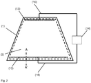
- FIG. 2 and Fig. 3 each show a detail of a transparent pane according to the invention with an electrically conductive coating as part of a composite pane.
- the composite pane is provided as a windshield of a passenger car.
- the transparent substrate 1 is connected to a second pane 12 via a thermoplastic intermediate layer 17.
- FIG. 2 shows a plan view of the side facing away from the thermoplastic intermediate layer surface of the transparent substrate 1.
- the transparent substrate 1 is the interior of the passenger car facing disc.
- the transparent substrate 1 and the second disk 12 contain float glass and each have a thickness of 2.1 mm.
- the thermoplastic intermediate layer 17 contains polyvinyl butyral (PVB) and has a thickness of 0.76 mm.
- PVB polyvinyl butyral
- An electrically conductive coating 2 is applied to the surface of the transparent substrate 1 facing the thermoplastic intermediate layer 17.
- the electrically conductive coating 2 is an electrically heatable coating and is electrically contacted for this purpose.
- the electrically conductive coating 2 extends over the entire surface of the transparent substrate 1 minus a circumferential frame-shaped coating-free region with a width b of 8 mm.
- the coating-free area is used for electrical insulation between the live electrically conductive coating 2 and the vehicle body.
- the coating-free region is hermetically sealed by bonding with the intermediate layer 17 in order to protect the electrically conductive coating 2 from damage and corrosion.
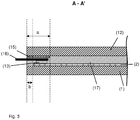
- Fig. 3 shows a section along AA 'through the composite disk according to FIG. 2 in the area of the lower edge.
- the transparent substrate 1 with the electrically conductive coating 2, the second pane 12, the thermoplastic intermediate layer 17, a bus bar 13, a feed line 16 and the covering pressure 15 can be seen.
- Fig. 4 shows a flowchart of an embodiment of the inventive method for producing a transparent pane with electrically conductive coating. 2
- a transparent pane according to the invention with an electrically conductive coating was produced.
- the layer sequence and the layer thicknesses for Examples 1 and 2 according to the invention are shown in Table 1.
- the transparent substrate 1 provided with the electrically conductive coating 2 was then bent at a temperature of about 650 ° C. The bending process took about 10 minutes.
- the thermoplastic intermediate layer contained polyvinyl butyral (PVB) and had a thickness of 0.76 mm.
- the electrically conductive coating 2 was arranged facing the thermoplastic intermediate layer 17.
- Table 1 material reference numeral layer thickness example 1 Example 2 SiZrN x : Al 9 40 nm 40 nm ZnO: Al 8.3 3.3 10 nm 10 nm NiCr 11.3 0.1 nm 0.1 nm Ag 7.3 16 nm 18 nm ZnO: Al 6.3 10 nm 10 nm SnZnO x : Sb 5.3 6 nm 6 nm SiZrN x : Al 4.3 59 nm 60 nm ZnO: Al 8.2 3.2 10 nm 10 nm NiCr 11.2 0.1 nm 0.1 nm Ag 7.2 16 nm 18 nm ZnO: Al 6.2 10 nm 10 nm SnZnO x : Sb 5.2 6 nm 6 nm SiZrN x : Al 4.2 63 nm 59 nm ZnO: Al
- the comparative examples were carried out in the same way as the examples. The difference was in the electrically conductive coating 2.
- no layers of optically high-refractive index material in the sense of the invention were arranged between each two electrically conductive silver layers, but rather dielectric layers containing silicon nitride. Such layers containing silicon nitride are known in the prior art for the separation of electrically conductive layers.
- the electrically conductive coating included only a smoothing layer containing antimony-doped tin-zinc oxide disposed below the lowermost silver layer.
- the electrically conductive coating comprised, as in the example according to the invention, a total of three smoothing layers containing antimony-doped tin-zinc oxide, each smoothing layer being arranged underneath each one electrically conductive silver layer.
- the layer thicknesses of the electrically conductive layers which contained silver were chosen exactly the same as in Example 1 according to the invention in the comparative examples.
- the exact layer sequence with layer thicknesses and materials of the comparative examples are shown in Table 2.
- Example 1 Due to the same thicknesses of the electrically conductive layers, the comparison between Example 1 according to the invention and the comparative examples illustrates the effect of the inventive design of the electrically conductive coating 2 with the layers of optically high-index material 4 on the sheet resistance.
- the electrically conductive coating 2 according to the invention in example 1 already had a surface resistance R square which was reduced by 16% compared with comparative example 1 before the temperature treatment. The temperature treatment resulted in a further reduction of sheet resistance R square . After temperature treatment and lamination, the sheet resistance R square of the electrically conductive coating 2 in the example according to the invention was lowered by 19% compared with comparative example 1.
- Example 1 The lowering of the sheet resistance R square of the electrically conductive coating 2 in Example 1 according to the invention compared to Comparative Example 1 is not exclusively due to the presence of the additional smoothing layers 5.2 and 5.3, as becomes clear from Comparative Example 2.
- the additional smoothing layers in Comparative Example 2 lead to a reduction in the surface resistance R square compared to Comparative Example 1 by 13% before the temperature treatment and by 15% after the temperature treatment.
- the particularly low sheet resistance of Example 1 with the inventive layers of optically high-refractive index materials 4.2 and 4.3 is not achieved in Comparative Example 2.
- the sheet resistance R squared is reduced by 5% compared to comparative example 2 before the temperature treatment and by 6% after the temperature treatment.
- Example 2 according to the invention had the same layer sequence as Example 1. However, the layer thicknesses were chosen differently than in Example 1. In particular, the electrically conductive coating 2 in Example 2 had thicker electrically conductive layers 7. As a result, the sheet resistance of the electrically conductive coating 2 could be further reduced.
- T L (A) denotes the total transmission of illuminant A, Ra * (D65 / 8 °) and Rb * (D65 / 8 °) the color coordinates in the L * a * b * color space with reflection of illuminant D65 and an incident angle of 8 °, Ta * (D65 / 8 °) and Tb * ( D65 / 8 °) the color coordinates in the L * a * b * color space with transmission of illuminant D65 and an incident angle of 8 °.
- the total transmission through the transparent pane according to the invention was greater than 70% after the temperature treatment.
- the color values in the L * a * b * color space were favorable.
- the transparent pane according to the invention fulfills the legal requirements regarding transmission and neutral coloration and can be used as glazing of vehicles.
- Table 4 R square [ohms / square] 0.66 T L (A) [%] 70.2 Ra * (D65 / 8 °) 1.9 Rb * (D65 / 8 °) -12.3 Ta * (D65 / 8 °) -6.7 Tb * (D65 / 8 °) 5.6
- the sheet resistance R square of the electrically conductive coating 2 is markedly reduced.
- the transparent pane according to the invention has a high transmission and a high color neutrality.
- the lower sheet resistance R square leads to an improvement in the specific heating power P when the electrically conductive coating 2 is used as an electrically heatable coating, with good optical properties of the transparent pane at the same time. This result was unexpected and surprising to the skilled person.
Landscapes
- Chemical & Material Sciences (AREA)
- Engineering & Computer Science (AREA)
- Chemical Kinetics & Catalysis (AREA)
- General Chemical & Material Sciences (AREA)
- Geochemistry & Mineralogy (AREA)
- Materials Engineering (AREA)
- Organic Chemistry (AREA)
- Life Sciences & Earth Sciences (AREA)
- Physics & Mathematics (AREA)
- Optics & Photonics (AREA)
- General Physics & Mathematics (AREA)
- Toxicology (AREA)
- Health & Medical Sciences (AREA)
- Civil Engineering (AREA)
- Structural Engineering (AREA)
- Laminated Bodies (AREA)
- Surface Treatment Of Glass (AREA)
- Joining Of Glass To Other Materials (AREA)
Priority Applications (1)
| Application Number | Priority Date | Filing Date | Title |
|---|---|---|---|
| EP12768818.2A EP2803246B1 (de) | 2012-01-10 | 2012-10-04 | Transparente scheibe mit elektrisch leitfähiger beschichtung |
Applications Claiming Priority (3)
| Application Number | Priority Date | Filing Date | Title |
|---|---|---|---|
| EP12150547 | 2012-01-10 | ||
| PCT/EP2012/069566 WO2013104438A1 (de) | 2012-01-10 | 2012-10-04 | Transparente scheibe mit elektrisch leitfähiger beschichtung |
| EP12768818.2A EP2803246B1 (de) | 2012-01-10 | 2012-10-04 | Transparente scheibe mit elektrisch leitfähiger beschichtung |
Publications (2)
| Publication Number | Publication Date |
|---|---|
| EP2803246A1 EP2803246A1 (de) | 2014-11-19 |
| EP2803246B1 true EP2803246B1 (de) | 2017-05-03 |
Family
ID=46970301
Family Applications (1)
| Application Number | Title | Priority Date | Filing Date |
|---|---|---|---|
| EP12768818.2A Active EP2803246B1 (de) | 2012-01-10 | 2012-10-04 | Transparente scheibe mit elektrisch leitfähiger beschichtung |
Country Status (12)
| Country | Link |
|---|---|
| US (1) | US9359807B2 (enExample) |
| EP (1) | EP2803246B1 (enExample) |
| JP (1) | JP5916894B2 (enExample) |
| KR (1) | KR101574456B1 (enExample) |
| CN (1) | CN104081876B (enExample) |
| BR (1) | BR112014012695B1 (enExample) |
| EA (1) | EA026887B1 (enExample) |
| ES (1) | ES2626057T3 (enExample) |
| MX (1) | MX2014008319A (enExample) |
| PL (1) | PL2803246T3 (enExample) |
| PT (1) | PT2803246T (enExample) |
| WO (1) | WO2013104438A1 (enExample) |
Cited By (9)
| Publication number | Priority date | Publication date | Assignee | Title |
|---|---|---|---|---|
| WO2022214369A1 (de) | 2021-04-09 | 2022-10-13 | Saint-Gobain Glass France | Beheizbare verbundscheibe für eine projektionsanordnung |
| DE202023103844U1 (de) | 2023-07-11 | 2023-08-01 | Saint-Gobain Glass France | Beheizbare Verbundscheibe |
| WO2024056340A1 (de) | 2022-09-15 | 2024-03-21 | Saint-Gobain Glass France | Verbundscheibe mit bereichsweise aufgebrachter beheizbarer reflexionsschicht |
| WO2024083807A1 (de) | 2022-10-18 | 2024-04-25 | Saint-Gobain Glass France | Selektiv beheizbare verbundscheibe |
| WO2025026800A1 (de) | 2023-08-03 | 2025-02-06 | Saint-Gobain Glass France | Monolithische fahrzeugscheibe |
| WO2025157878A1 (de) | 2024-01-26 | 2025-07-31 | Saint-Gobain Sekurit France | Heizsystem mit einer fahrzeugscheibe |
| WO2025188281A1 (en) * | 2024-03-06 | 2025-09-12 | Turkiye Sise Ve Cam Fabrikalari Anonim Sirketi | A laminated windshield with an opaque layer |
| WO2025209806A1 (de) | 2024-04-03 | 2025-10-09 | Saint-Gobain Sekurit France | Selektiv beheizbare fahrzeugscheibe |
| WO2025219178A1 (de) | 2024-04-17 | 2025-10-23 | Saint-Gobain Sekurit France | FAHRZEUG MIT AUßENVORRICHTUNG, FAHRZEUGSCHEIBE UND IR-STRAHLUNGSQUELLE |
Families Citing this family (72)
| Publication number | Priority date | Publication date | Assignee | Title |
|---|---|---|---|---|
| US8889272B2 (en) | 2012-11-19 | 2014-11-18 | Guardian Industries Corp. | Coated article with low-E coating including tin oxide inclusive layer(s) with additional metal(s) |
| JP6253663B2 (ja) * | 2012-12-17 | 2017-12-27 | サン−ゴバン グラス フランスSaint−Gobain Glass France | 導電性コーティングを備える透明な板ガラス及びその製造方法 |
| ES2834128T3 (es) | 2013-12-12 | 2021-06-16 | Saint Gobain | Película termoplástica para una hoja de vidrio laminado con inserto de cuña continuo no lineal en dirección vertical y horizontal |
| JP6664377B2 (ja) * | 2014-07-25 | 2020-03-13 | エージーシー グラス ユーロップAgc Glass Europe | 装飾用ガラスパネル |
| EP2977202A1 (fr) * | 2014-07-25 | 2016-01-27 | AGC Glass Europe | Vitrage chauffant |
| KR20170093892A (ko) | 2014-12-08 | 2017-08-16 | 쌩-고벵 글래스 프랑스 | 헤드업 디스플레이 (hud)를 위한 감소된 두께를 갖는 적층 유리 |
| EP3034297A1 (fr) * | 2014-12-19 | 2016-06-22 | AGC Glass Europe | Vitrage feuilleté |
| US10678050B2 (en) | 2015-06-11 | 2020-06-09 | Saint-Gobain Glass France | Projection arrangement for a contact analog head-up display (HUD) |
| CN106489096B (zh) | 2015-06-11 | 2019-09-03 | 法国圣戈班玻璃厂 | 用于平视显示器(hud)的投影装置 |
| FR3038596B1 (fr) * | 2015-07-08 | 2021-12-10 | Saint Gobain | Materiau muni d'un empilement a proprietes thermiques |
| FR3038597B1 (fr) * | 2015-07-08 | 2021-12-10 | Saint Gobain | Materiau muni d'un empilement a proprietes thermiques |
| RU2692339C1 (ru) | 2015-10-23 | 2019-06-24 | Сэн-Гобэн Гласс Франс | Способ изготовления многослойного стекла с отражающим инфракрасное излучение покрытием на пленочной подложке |
| US20180250918A1 (en) | 2015-12-16 | 2018-09-06 | Saint-Gobain Glass France | Heatable laminated glass comprising a thin inner pane and a thin outer pane |
| RU2701385C1 (ru) | 2015-12-17 | 2019-09-26 | Сэн-Гобэн Гласс Франс | Способ восстановления подложек с электропроводным покрытием и рисунком лазерной резки |
| KR20180114131A (ko) | 2016-03-17 | 2018-10-17 | 쌩-고벵 글래스 프랑스 | 헤드-업 디스플레이를 위한 전기 전도 코팅을 가지는 복합 판유리 |
| JP6841844B2 (ja) * | 2016-05-17 | 2021-03-10 | サン−ゴバン グラス フランス | 透明ペイン |
| US10138158B2 (en) * | 2017-03-10 | 2018-11-27 | Guardian Glass, LLC | Coated article having low-E coating with IR reflecting layer(s) and high index nitrided dielectric layers |
| GB201711553D0 (en) * | 2017-07-18 | 2017-08-30 | Pilkington Group Ltd | Laminated glazing |
| KR102082424B1 (ko) * | 2017-07-25 | 2020-02-27 | 주식회사 케이씨씨 | 저방사 유리 |
| US10788667B2 (en) | 2017-08-31 | 2020-09-29 | Vitro Flat Glass Llc | Heads-up display and coating therefor |
| US20210107256A1 (en) | 2017-09-22 | 2021-04-15 | Saint-Gobain Glass France | Method of producing a coated vehicle windshield for a head-up display (hud) |
| US11248289B2 (en) * | 2017-11-10 | 2022-02-15 | Dallas Thin Films | Multilayered corrosion and anti-galling coating for threads and wearable materials |
| RU2745553C1 (ru) | 2017-11-30 | 2021-03-26 | Сэн-Гобэн Гласс Франс | Стеклопакет с интегрированным электрическим дополнительным элементом |
| GB201719994D0 (en) | 2017-11-30 | 2018-01-17 | Pilkington Group Ltd | Conductive pattern sheet, glazing having the same, vehicle having the glazing, method of manufacturing the sheet and method of manufacturing the glazing |
| CN110418715A (zh) | 2018-02-28 | 2019-11-05 | 法国圣戈班玻璃厂 | 具有红外辐射反射元件的复合玻璃板 |
| GB2572146A (en) | 2018-03-19 | 2019-09-25 | Diamond Coatings Ltd | Laminated substrate |
| US11526009B2 (en) | 2018-03-22 | 2022-12-13 | Saint-Gobain Glass France | Projection arrangement for a head-up display (HUD) with P-polarised light portions |
| WO2019179682A1 (de) | 2018-03-22 | 2019-09-26 | Saint-Gobain Glass France | Verbundscheibe für ein head-up-display mit elektrisch leitfähiger beschichtung und antireflexionsbeschichtung |
| BR112020021670A2 (pt) | 2018-04-25 | 2021-01-26 | Saint-Gobain Glass France | vidraça compósita com elemento funcional eletricamente comutável em camada intermediária termoplástica |
| WO2019206493A1 (de) | 2018-04-26 | 2019-10-31 | Saint-Gobain Glass France | Verbundscheibe mit elektrisch leitfähiger beschichtung und antireflexionsbeschichtung |
| FR3082199B1 (fr) * | 2018-06-12 | 2020-06-26 | Saint-Gobain Glass France | Materiau comprenant un empilement a proprietes thermiques et esthetiques |
| FR3082198B1 (fr) * | 2018-06-12 | 2020-06-26 | Saint-Gobain Glass France | Materiau comprenant un empilement a proprietes thermiques et esthetique |
| KR102490258B1 (ko) | 2018-06-28 | 2023-01-20 | 쌩-고벵 글래스 프랑스 | 전기적으로 전환 가능한 광학 특성과 개선된 전기적 접촉을 갖는 다층 필름 |
| CN111356949B (zh) | 2018-10-24 | 2023-10-31 | 法国圣戈班玻璃厂 | 用于车辆的投影装置,包含侧玻璃 |
| PE20210989A1 (es) | 2018-11-09 | 2021-06-01 | Saint Gobain | Disposicion de proyeccion para una pantalla de proyeccion superior integrada (hud) con radiacion de polarizacion p. |
| JP7303873B2 (ja) | 2018-11-09 | 2023-07-05 | サン-ゴバン グラス フランス | p-偏光放射を用いるヘッドアップディスプレイ(HUD)のための投影設備 |
| KR102659107B1 (ko) * | 2018-12-31 | 2024-04-18 | 쌩-고벵 글래스 프랑스 | 다층 박막이 구비된 투명 기판 및 이를 포함하는 다중 글레이징 유닛 |
| KR102156988B1 (ko) * | 2018-12-31 | 2020-09-16 | 에스케이씨 주식회사 | 유리접합용 필름, 이의 제조방법, 이를 포함하는 접합유리 및 이를 포함하는 이동수단 |
| FR3092107B1 (fr) * | 2019-01-30 | 2022-08-12 | Saint Gobain | Substrat muni d’un empilement a proprietes thermiques et a couche absorbante |
| DE202019102388U1 (de) | 2019-04-29 | 2019-05-06 | Saint-Gobain Glass France | Verbundscheibe mit einer elektrisch leitfähigen Beschichtung und einem dielektrischen Übergitter |
| DE202019102486U1 (de) | 2019-05-03 | 2019-05-13 | Saint-Gobain Glass France | Verbundscheibe mit einer elektrisch leitfähigen Beschichtung und einem lumineszierenden Material zur Einstellung der Reflexionsfarbe |
| DE202019104357U1 (de) | 2019-08-08 | 2019-08-14 | Saint-Gobain Sekurit Deutschland Gmbh & Co. Kg | Verbesserte Widerstandsfähigkeit von PDLC-Folien gegen Strahlung durch IR- und UV-reflektierende Beschichtungen auf Seite II einer Verbundscheibe |
| US11604307B1 (en) * | 2019-09-24 | 2023-03-14 | United States Of America As Represented By The Administrator Of Nasa | Dark mirror optical stack and related systems |
| KR102697670B1 (ko) | 2019-11-28 | 2024-08-23 | 쌩-고벵 글래스 프랑스 | 중간층에 통합된 기능소자와 탈기구조를 갖는 복합 판유리 |
| CN113543970A (zh) | 2020-02-12 | 2021-10-22 | 法国圣戈班玻璃厂 | 具有集成的温度传感器的交通工具玻璃板 |
| WO2021209289A1 (de) | 2020-04-15 | 2021-10-21 | Saint-Gobain Glass France | Fahrzeugverglasung mit sonnenschutzbeschichtung |
| CN114144242B (zh) * | 2020-06-16 | 2023-10-03 | 法国圣戈班玻璃厂 | 复合板 |
| KR102408459B1 (ko) * | 2020-06-17 | 2022-06-13 | 한국유리공업 주식회사 | 박막 다층 코팅이 구비된 투명 기재 |
| CN114258508A (zh) | 2020-07-20 | 2022-03-29 | 法国圣戈班玻璃厂 | 具有p偏振辐射的平视显示器(HUD)的投影装置 |
| EP4214049A1 (de) * | 2020-09-18 | 2023-07-26 | Sage Electrochromics, Inc. | Scheibe mit funktionselement mit elektrisch schaltbaren optischen eigenschaften und muster für hochfrequenz-transmission |
| US12420528B2 (en) | 2020-10-01 | 2025-09-23 | Saint-Gobain Glass France | Composite pane |
| DE202020105642U1 (de) | 2020-10-01 | 2022-01-07 | Saint-Gobain Sekurit Deutschland Gmbh & Co. Kg | Verbundscheibe |
| KR102839535B1 (ko) | 2020-11-27 | 2025-07-29 | 쌩-고벵 글래스 프랑스 | 차양 코팅을 포함하는 복합 판유리 |
| EP4284637B1 (de) | 2021-01-28 | 2024-11-06 | Saint-Gobain Glass France | Verbundscheibe mit verbesserter farbwirkung |
| EP4308378A1 (de) | 2021-03-17 | 2024-01-24 | Saint-Gobain Glass France | Verbundscheibe für ein fahrzeugdach mit sicherheitssensor zur innenraumüberwachung |
| CN117120390A (zh) | 2021-04-22 | 2023-11-24 | 法国圣戈班玻璃厂 | 带有具有金属纳米晶体的非连续金属层的红外反射涂层的交通工具玻璃板 |
| CN115551706A (zh) | 2021-04-29 | 2022-12-30 | 法国圣戈班玻璃厂 | 带有功能膜和集流器的复合片材 |
| CN115697696A (zh) | 2021-05-31 | 2023-02-03 | 法国圣戈班玻璃厂 | 具有导电涂层和至少一个包含选择性吸收纳米颗粒的层的复合玻璃板 |
| EP4123357A1 (en) * | 2021-07-23 | 2023-01-25 | Ficosa Adas, S.L.U. | Lens assembly, camera module having a lens assembly for motor vehicles, and a method for making a lens assembly |
| CN113682007A (zh) * | 2021-08-23 | 2021-11-23 | 福耀玻璃工业集团股份有限公司 | 具有透明导电层的夹层玻璃及其制备方法 |
| EP4440835A1 (de) | 2021-11-30 | 2024-10-09 | Saint-Gobain Glass France | Verbundscheibe mit einer elektrisch leitfähigen beschichtung und lokaler antireflexbeschichtung |
| CN119654661A (zh) | 2022-07-29 | 2025-03-18 | 法国圣戈班玻璃厂 | 用于驾驶员辅助系统的布置 |
| EP4340540A1 (de) | 2022-09-13 | 2024-03-20 | Saint-Gobain Glass France | Verfahren zum herstellen einer fahrzeugscheibe mit elektrisch leitfähiger sprühschicht |
| DE202022105849U1 (de) | 2022-10-18 | 2022-11-09 | Saint-Gobain SEKURIT Deutschland GmbH | Beheizbare Verbundscheibe mit einer Beschichtung auf Basis eines photothermischen Materials |
| WO2024115113A1 (de) | 2022-11-29 | 2024-06-06 | Saint-Gobain Glass France | Anordnung für die kombination eines fahrerassistenzsystems und einer projektionsanordnung für ein fahrzeug |
| CN120513168A (zh) | 2023-02-09 | 2025-08-19 | 法国圣戈班玻璃厂 | 用于平视显示器的投影组装件 |
| DE202024002550U1 (de) | 2023-02-28 | 2025-07-28 | Saint-Gobain Sekurit France | Verglasungseinheit mit elektronischer Komponente |
| DE202024002602U1 (de) | 2023-06-07 | 2025-09-24 | Saint-Gobain Sekurit France | Beheizbare Verbundscheibe |
| CN120916893A (zh) | 2023-06-07 | 2025-11-07 | 法国圣戈班安全玻璃公司 | 具有加热装置的层压片材 |
| WO2025017270A1 (en) * | 2023-07-20 | 2025-01-23 | Shanghai Yaohua Pilkington Glass Group Co.,Ltd., | Vehicular glazing |
| WO2025073400A1 (de) | 2023-10-05 | 2025-04-10 | Saint-Gobain Glass France | Verbundscheibe mit einer ir-reflektierenden beschichtung |
| WO2025219179A1 (de) | 2024-04-17 | 2025-10-23 | Saint-Gobain Sekurit France | Seitenkamera mit ir-strahlungsquelle für ein fahrzeug |
Family Cites Families (31)
| Publication number | Priority date | Publication date | Assignee | Title |
|---|---|---|---|---|
| DE2936398A1 (de) | 1979-09-08 | 1981-03-26 | Ver Glaswerke Gmbh | Elektrisch beheizbare glasscheibe |
| US4902580A (en) * | 1988-04-01 | 1990-02-20 | Ppg Industries, Inc. | Neutral reflecting coated articles with sputtered multilayer films of metal oxides |
| JPH05502310A (ja) * | 1990-08-30 | 1993-04-22 | バイラテック・シン・フィルムズ・インコーポレイテッド | 酸化ニオブを含むdc反応性スパッタリングされた光学被覆 |
| DE9313394U1 (de) | 1992-10-17 | 1993-10-28 | Vegla Vereinigte Glaswerke Gmbh, 52066 Aachen | Autoglasscheibe aus Verbundglas mit in der Zwischenschicht eingebetteten Drähten und einem Anschlußkabel |
| DE4235063A1 (de) | 1992-10-17 | 1994-04-21 | Ver Glaswerke Gmbh | Autoglasscheibe aus Verbundglas mit in der Zwischenschicht eingebetteten Drähten und einem Anschlußkabel |
| FR2701475B1 (fr) * | 1993-02-11 | 1995-03-31 | Saint Gobain Vitrage Int | Substrats en verre revêtus d'un empilement de couches minces, application à des vitrages à propriétés de réflexion dans l'infra-rouge et/ou à propriétés dans le domaine du rayonnement solaire. |
| CA2129488C (fr) | 1993-08-12 | 2004-11-23 | Olivier Guiselin | Substrats transparents munis d'un empilement de couches minces, application aux vitrages d'isolation thermique et/ou de protection solaire |
| FR2757151B1 (fr) | 1996-12-12 | 1999-01-08 | Saint Gobain Vitrage | Vitrage comprenant un substrat muni d'un empilement de couches minces pour la protection solaire et/ou l'isolation thermique |
| DE19848751C1 (de) | 1998-10-22 | 1999-12-16 | Ver Glaswerke Gmbh | Schichtsystem für transparente Substrate |
| US6576349B2 (en) * | 2000-07-10 | 2003-06-10 | Guardian Industries Corp. | Heat treatable low-E coated articles and methods of making same |
| JP4052941B2 (ja) | 2000-09-29 | 2008-02-27 | 日本板硝子株式会社 | 低放射率透明積層体 |
| US6734396B2 (en) | 2001-09-07 | 2004-05-11 | Centre Luxembourgeois De Recherches Pour Le Verre Et La Ceramique S.A. (C.R.V.C.) | Heatable vehicle window with different voltages in different heatable zones |
| DE10333618B3 (de) | 2003-07-24 | 2005-03-24 | Saint-Gobain Sekurit Deutschland Gmbh & Co. Kg | Substrat mit einer elektrisch leitfähigen Beschichtung und einem Kommunikationsfenster |
| FR2858816B1 (fr) | 2003-08-13 | 2006-11-17 | Saint Gobain | Substrat transparent comportant un revetement antireflet |
| FR2859721B1 (fr) | 2003-09-17 | 2006-08-25 | Saint Gobain | Substrat transparent muni d'un empilement de couches minces pour un blindage electromagnetique |
| DE10352464A1 (de) | 2003-11-07 | 2005-06-23 | Saint-Gobain Sekurit Deutschland Gmbh & Co. Kg | Heizbare Verbundscheibe |
| FR2862961B1 (fr) | 2003-11-28 | 2006-02-17 | Saint Gobain | Substrat transparent utilisable alternativement ou cumulativement pour le controle thermique, le blindage electromagnetique et le vitrage chauffant. |
| US7217460B2 (en) * | 2004-03-11 | 2007-05-15 | Guardian Industries Corp. | Coated article with low-E coating including tin oxide interlayer |
| DE202004019286U1 (de) | 2004-12-14 | 2006-04-20 | Saint-Gobain Sekurit Deutschland Gmbh & Co. Kg | Flachleiter-Anschlusselement für Fensterscheiben |
| US7335421B2 (en) | 2005-07-20 | 2008-02-26 | Ppg Industries Ohio, Inc. | Heatable windshield |
| FR2898122B1 (fr) * | 2006-03-06 | 2008-12-05 | Saint Gobain | Substrat muni d'un empilement a proprietes thermiques |
| FR2898123B1 (fr) * | 2006-03-06 | 2008-12-05 | Saint Gobain | Substrat muni d'un empilement a proprietes thermiques |
| US8203073B2 (en) * | 2006-11-02 | 2012-06-19 | Guardian Industries Corp. | Front electrode for use in photovoltaic device and method of making same |
| US8686319B2 (en) * | 2007-05-09 | 2014-04-01 | Ppg Industries Ohio, Inc. | Vehicle transparency heated with alternating current |
| FR2919110A1 (fr) | 2007-07-16 | 2009-01-23 | Saint Gobain | Substrat de face avant d'ecran plasma, utilisation et procede de fabrication |
| WO2009029466A1 (en) | 2007-08-24 | 2009-03-05 | Ppg Industries Ohio, Inc. | Vehicle transparency |
| EP2255372A2 (fr) * | 2008-02-18 | 2010-12-01 | Saint-Gobain Glass France | Cellule photovoltaique et substrat de cellule photovoltaique |
| FR2940271B1 (fr) * | 2008-12-22 | 2011-10-21 | Saint Gobain | Substrat muni d'un empilement a proprietes thermiques et a couche(s) absorbante(s) |
| FR2949226B1 (fr) | 2009-08-21 | 2011-09-09 | Saint Gobain | Substrat muni d'un empilement a proprietes thermiques, en particulier pour realiser un vitrage chauffant. |
| CN104025704B (zh) * | 2012-01-10 | 2016-10-12 | 法国圣戈班玻璃厂 | 带有导电涂层的透明玻璃 |
| JP6253663B2 (ja) * | 2012-12-17 | 2017-12-27 | サン−ゴバン グラス フランスSaint−Gobain Glass France | 導電性コーティングを備える透明な板ガラス及びその製造方法 |
-
2012
- 2012-10-04 CN CN201280066685.9A patent/CN104081876B/zh active Active
- 2012-10-04 KR KR1020147018799A patent/KR101574456B1/ko active Active
- 2012-10-04 EA EA201491353A patent/EA026887B1/ru not_active IP Right Cessation
- 2012-10-04 EP EP12768818.2A patent/EP2803246B1/de active Active
- 2012-10-04 WO PCT/EP2012/069566 patent/WO2013104438A1/de not_active Ceased
- 2012-10-04 PL PL12768818T patent/PL2803246T3/pl unknown
- 2012-10-04 ES ES12768818.2T patent/ES2626057T3/es active Active
- 2012-10-04 MX MX2014008319A patent/MX2014008319A/es active IP Right Grant
- 2012-10-04 US US14/358,656 patent/US9359807B2/en active Active
- 2012-10-04 BR BR112014012695-0A patent/BR112014012695B1/pt not_active IP Right Cessation
- 2012-10-04 PT PT127688182T patent/PT2803246T/pt unknown
- 2012-10-04 JP JP2014551539A patent/JP5916894B2/ja active Active
Non-Patent Citations (1)
| Title |
|---|
| None * |
Cited By (10)
| Publication number | Priority date | Publication date | Assignee | Title |
|---|---|---|---|---|
| WO2022214369A1 (de) | 2021-04-09 | 2022-10-13 | Saint-Gobain Glass France | Beheizbare verbundscheibe für eine projektionsanordnung |
| US12409636B2 (en) | 2021-04-09 | 2025-09-09 | Saint-Gobain Glass France | Heatable composite pane for a projection assembly |
| WO2024056340A1 (de) | 2022-09-15 | 2024-03-21 | Saint-Gobain Glass France | Verbundscheibe mit bereichsweise aufgebrachter beheizbarer reflexionsschicht |
| WO2024083807A1 (de) | 2022-10-18 | 2024-04-25 | Saint-Gobain Glass France | Selektiv beheizbare verbundscheibe |
| DE202023103844U1 (de) | 2023-07-11 | 2023-08-01 | Saint-Gobain Glass France | Beheizbare Verbundscheibe |
| WO2025026800A1 (de) | 2023-08-03 | 2025-02-06 | Saint-Gobain Glass France | Monolithische fahrzeugscheibe |
| WO2025157878A1 (de) | 2024-01-26 | 2025-07-31 | Saint-Gobain Sekurit France | Heizsystem mit einer fahrzeugscheibe |
| WO2025188281A1 (en) * | 2024-03-06 | 2025-09-12 | Turkiye Sise Ve Cam Fabrikalari Anonim Sirketi | A laminated windshield with an opaque layer |
| WO2025209806A1 (de) | 2024-04-03 | 2025-10-09 | Saint-Gobain Sekurit France | Selektiv beheizbare fahrzeugscheibe |
| WO2025219178A1 (de) | 2024-04-17 | 2025-10-23 | Saint-Gobain Sekurit France | FAHRZEUG MIT AUßENVORRICHTUNG, FAHRZEUGSCHEIBE UND IR-STRAHLUNGSQUELLE |
Also Published As
| Publication number | Publication date |
|---|---|
| BR112014012695A2 (pt) | 2017-06-13 |
| JP2015509866A (ja) | 2015-04-02 |
| EA201491353A1 (ru) | 2015-04-30 |
| BR112014012695A8 (pt) | 2017-06-20 |
| PT2803246T (pt) | 2017-06-23 |
| WO2013104438A1 (de) | 2013-07-18 |
| MX2014008319A (es) | 2014-08-21 |
| KR20140099547A (ko) | 2014-08-12 |
| ES2626057T3 (es) | 2017-07-21 |
| JP5916894B2 (ja) | 2016-05-11 |
| KR101574456B1 (ko) | 2015-12-11 |
| US9359807B2 (en) | 2016-06-07 |
| EP2803246A1 (de) | 2014-11-19 |
| CN104081876B (zh) | 2016-08-31 |
| CN104081876A (zh) | 2014-10-01 |
| US20140362434A1 (en) | 2014-12-11 |
| EA026887B1 (ru) | 2017-05-31 |
| PL2803246T3 (pl) | 2017-09-29 |
| BR112014012695B1 (pt) | 2021-01-19 |
Similar Documents
| Publication | Publication Date | Title |
|---|---|---|
| EP2803246B1 (de) | Transparente scheibe mit elektrisch leitfähiger beschichtung | |
| EP2803245B1 (de) | Transparente scheibe mit elektrisch leitfähiger beschichtung | |
| EP2630098B1 (de) | Transparente scheibe | |
| EP2931673B1 (de) | Transparente scheibe mit elektrisch leitfähiger beschichtung | |
| EP3877176B1 (de) | Projektionsanordnung für ein head-up-display (hud) mit p-polarisierter strahlung | |
| EP3877177B1 (de) | Projektionsanordnung für ein head-up-display (hud) mit p-polarisierter strahlung | |
| EP3720701B1 (de) | Verbundscheibe mit sonnenschutzbeschichtung und wärmestrahlen reflektierender beschichtung | |
| EP2822907B1 (de) | Kraftfahrzeugscheibe mit wärmestrahlung reflektierender beschichtung | |
| DE60026157T2 (de) | Verglasung | |
| EP3365174B1 (de) | Verfahren zur herstellung einer verbundscheibe mit infrarotreflektierender beschichtung auf einer trägerfolie | |
| EP3390044B1 (de) | Beheizbares verbundglas mit dünner innenscheibe und dünner aussenscheibe | |
| WO2017198362A1 (de) | Transparente scheibe | |
| EP4251417A1 (de) | Verbundscheibe mit sonnenschutzbeschichtung | |
| EP4214050B1 (de) | Projektionsanordnung für ein head-up-display (hud) mit p-polarisierter strahlung | |
| EP4251418A1 (de) | Verbundscheibe mit sonnenschutzbeschichtung | |
| EP4395991A1 (de) | Fahrzeugverbundscheibe | |
| WO2022017707A1 (de) | Projektionsanordnung für ein head-up-display (hud) mit p-polarisierter strahlung | |
| EP4385286A1 (de) | Beheizbare fahrzeugverglasung | |
| EP4353050A1 (de) | Scheibe mit muster-förmiger funktionsbeschichtung | |
| DE202019104357U1 (de) | Verbesserte Widerstandsfähigkeit von PDLC-Folien gegen Strahlung durch IR- und UV-reflektierende Beschichtungen auf Seite II einer Verbundscheibe | |
| EP4347255B1 (de) | Verbundscheibe mit einer elektrisch leitfähigen beschichtung und mindestens einer schicht umfassend selektiv absorbierende nanopartikel | |
| DE102023100216B3 (de) | Verbundscheibe mit Sonnenschutzbeschichtung und Wärmestrahlen reflektierender Beschichtung sowie deren Verwendung | |
| WO2025073400A1 (de) | Verbundscheibe mit einer ir-reflektierenden beschichtung | |
| WO2023143959A1 (de) | Projektionsanordnung für ein head-up-display (hud) mit p-polarisierter strahlung | |
| WO2024041799A1 (de) | Fahrzeugscheibe mit opaker abdeckschicht |
Legal Events
| Date | Code | Title | Description |
|---|---|---|---|
| PUAI | Public reference made under article 153(3) epc to a published international application that has entered the european phase |
Free format text: ORIGINAL CODE: 0009012 |
|
| 17P | Request for examination filed |
Effective date: 20140611 |
|
| AK | Designated contracting states |
Kind code of ref document: A1 Designated state(s): AL AT BE BG CH CY CZ DE DK EE ES FI FR GB GR HR HU IE IS IT LI LT LU LV MC MK MT NL NO PL PT RO RS SE SI SK SM TR |
|
| RIN1 | Information on inventor provided before grant (corrected) |
Inventor name: NEANDER, MARCUS Inventor name: SCHMITZ, CHRISTOPH Inventor name: BILLERT, ULRICH Inventor name: LUXEMBOURG, DAVID Inventor name: FISCHER, KLAUS Inventor name: JANZYK, SEBASTIAN |
|
| DAX | Request for extension of the european patent (deleted) | ||
| GRAP | Despatch of communication of intention to grant a patent |
Free format text: ORIGINAL CODE: EPIDOSNIGR1 |
|
| STAA | Information on the status of an ep patent application or granted ep patent |
Free format text: STATUS: GRANT OF PATENT IS INTENDED |
|
| GRAS | Grant fee paid |
Free format text: ORIGINAL CODE: EPIDOSNIGR3 |
|
| GRAA | (expected) grant |
Free format text: ORIGINAL CODE: 0009210 |
|
| STAA | Information on the status of an ep patent application or granted ep patent |
Free format text: STATUS: THE PATENT HAS BEEN GRANTED |
|
| INTG | Intention to grant announced |
Effective date: 20170309 |
|
| AK | Designated contracting states |
Kind code of ref document: B1 Designated state(s): AL AT BE BG CH CY CZ DE DK EE ES FI FR GB GR HR HU IE IS IT LI LT LU LV MC MK MT NL NO PL PT RO RS SE SI SK SM TR |
|
| REG | Reference to a national code |
Ref country code: GB Ref legal event code: FG4D Free format text: NOT ENGLISH |
|
| REG | Reference to a national code |
Ref country code: AT Ref legal event code: REF Ref document number: 891282 Country of ref document: AT Kind code of ref document: T Effective date: 20170515 Ref country code: CH Ref legal event code: EP |
|
| REG | Reference to a national code |
Ref country code: NL Ref legal event code: FP |
|
| REG | Reference to a national code |
Ref country code: IE Ref legal event code: FG4D Free format text: LANGUAGE OF EP DOCUMENT: GERMAN |
|
| REG | Reference to a national code |
Ref country code: DE Ref legal event code: R096 Ref document number: 502012010252 Country of ref document: DE |
|
| REG | Reference to a national code |
Ref country code: PT Ref legal event code: SC4A Ref document number: 2803246 Country of ref document: PT Date of ref document: 20170623 Kind code of ref document: T Free format text: AVAILABILITY OF NATIONAL TRANSLATION Effective date: 20170609 |
|
| REG | Reference to a national code |
Ref country code: RO Ref legal event code: EPE |
|
| REG | Reference to a national code |
Ref country code: SE Ref legal event code: TRGR |
|
| REG | Reference to a national code |
Ref country code: ES Ref legal event code: FG2A Ref document number: 2626057 Country of ref document: ES Kind code of ref document: T3 Effective date: 20170721 |
|
| REG | Reference to a national code |
Ref country code: FR Ref legal event code: PLFP Year of fee payment: 6 |
|
| REG | Reference to a national code |
Ref country code: LT Ref legal event code: MG4D |
|
| PG25 | Lapsed in a contracting state [announced via postgrant information from national office to epo] |
Ref country code: HR Free format text: LAPSE BECAUSE OF FAILURE TO SUBMIT A TRANSLATION OF THE DESCRIPTION OR TO PAY THE FEE WITHIN THE PRESCRIBED TIME-LIMIT Effective date: 20170503 Ref country code: FI Free format text: LAPSE BECAUSE OF FAILURE TO SUBMIT A TRANSLATION OF THE DESCRIPTION OR TO PAY THE FEE WITHIN THE PRESCRIBED TIME-LIMIT Effective date: 20170503 Ref country code: GR Free format text: LAPSE BECAUSE OF FAILURE TO SUBMIT A TRANSLATION OF THE DESCRIPTION OR TO PAY THE FEE WITHIN THE PRESCRIBED TIME-LIMIT Effective date: 20170804 Ref country code: NO Free format text: LAPSE BECAUSE OF FAILURE TO SUBMIT A TRANSLATION OF THE DESCRIPTION OR TO PAY THE FEE WITHIN THE PRESCRIBED TIME-LIMIT Effective date: 20170803 Ref country code: LT Free format text: LAPSE BECAUSE OF FAILURE TO SUBMIT A TRANSLATION OF THE DESCRIPTION OR TO PAY THE FEE WITHIN THE PRESCRIBED TIME-LIMIT Effective date: 20170503 |
|
| REG | Reference to a national code |
Ref country code: SK Ref legal event code: T3 Ref document number: E 24511 Country of ref document: SK |
|
| PG25 | Lapsed in a contracting state [announced via postgrant information from national office to epo] |
Ref country code: LV Free format text: LAPSE BECAUSE OF FAILURE TO SUBMIT A TRANSLATION OF THE DESCRIPTION OR TO PAY THE FEE WITHIN THE PRESCRIBED TIME-LIMIT Effective date: 20170503 Ref country code: BG Free format text: LAPSE BECAUSE OF FAILURE TO SUBMIT A TRANSLATION OF THE DESCRIPTION OR TO PAY THE FEE WITHIN THE PRESCRIBED TIME-LIMIT Effective date: 20170803 Ref country code: IS Free format text: LAPSE BECAUSE OF FAILURE TO SUBMIT A TRANSLATION OF THE DESCRIPTION OR TO PAY THE FEE WITHIN THE PRESCRIBED TIME-LIMIT Effective date: 20170903 Ref country code: RS Free format text: LAPSE BECAUSE OF FAILURE TO SUBMIT A TRANSLATION OF THE DESCRIPTION OR TO PAY THE FEE WITHIN THE PRESCRIBED TIME-LIMIT Effective date: 20170503 |
|
| PG25 | Lapsed in a contracting state [announced via postgrant information from national office to epo] |
Ref country code: DK Free format text: LAPSE BECAUSE OF FAILURE TO SUBMIT A TRANSLATION OF THE DESCRIPTION OR TO PAY THE FEE WITHIN THE PRESCRIBED TIME-LIMIT Effective date: 20170503 Ref country code: EE Free format text: LAPSE BECAUSE OF FAILURE TO SUBMIT A TRANSLATION OF THE DESCRIPTION OR TO PAY THE FEE WITHIN THE PRESCRIBED TIME-LIMIT Effective date: 20170503 |
|
| REG | Reference to a national code |
Ref country code: DE Ref legal event code: R097 Ref document number: 502012010252 Country of ref document: DE |
|
| PG25 | Lapsed in a contracting state [announced via postgrant information from national office to epo] |
Ref country code: SM Free format text: LAPSE BECAUSE OF FAILURE TO SUBMIT A TRANSLATION OF THE DESCRIPTION OR TO PAY THE FEE WITHIN THE PRESCRIBED TIME-LIMIT Effective date: 20170503 |
|
| PLBE | No opposition filed within time limit |
Free format text: ORIGINAL CODE: 0009261 |
|
| STAA | Information on the status of an ep patent application or granted ep patent |
Free format text: STATUS: NO OPPOSITION FILED WITHIN TIME LIMIT |
|
| 26N | No opposition filed |
Effective date: 20180206 |
|
| PG25 | Lapsed in a contracting state [announced via postgrant information from national office to epo] |
Ref country code: MC Free format text: LAPSE BECAUSE OF FAILURE TO SUBMIT A TRANSLATION OF THE DESCRIPTION OR TO PAY THE FEE WITHIN THE PRESCRIBED TIME-LIMIT Effective date: 20170503 Ref country code: SI Free format text: LAPSE BECAUSE OF FAILURE TO SUBMIT A TRANSLATION OF THE DESCRIPTION OR TO PAY THE FEE WITHIN THE PRESCRIBED TIME-LIMIT Effective date: 20170503 |
|
| REG | Reference to a national code |
Ref country code: CH Ref legal event code: PL |
|
| REG | Reference to a national code |
Ref country code: IE Ref legal event code: MM4A |
|
| PG25 | Lapsed in a contracting state [announced via postgrant information from national office to epo] |
Ref country code: LI Free format text: LAPSE BECAUSE OF NON-PAYMENT OF DUE FEES Effective date: 20171031 Ref country code: CH Free format text: LAPSE BECAUSE OF NON-PAYMENT OF DUE FEES Effective date: 20171031 |
|
| REG | Reference to a national code |
Ref country code: FR Ref legal event code: PLFP Year of fee payment: 7 |
|
| PG25 | Lapsed in a contracting state [announced via postgrant information from national office to epo] |
Ref country code: MT Free format text: LAPSE BECAUSE OF FAILURE TO SUBMIT A TRANSLATION OF THE DESCRIPTION OR TO PAY THE FEE WITHIN THE PRESCRIBED TIME-LIMIT Effective date: 20170503 |
|
| PG25 | Lapsed in a contracting state [announced via postgrant information from national office to epo] |
Ref country code: IE Free format text: LAPSE BECAUSE OF NON-PAYMENT OF DUE FEES Effective date: 20171004 |
|
| REG | Reference to a national code |
Ref country code: AT Ref legal event code: MM01 Ref document number: 891282 Country of ref document: AT Kind code of ref document: T Effective date: 20171004 |
|
| PG25 | Lapsed in a contracting state [announced via postgrant information from national office to epo] |
Ref country code: AT Free format text: LAPSE BECAUSE OF NON-PAYMENT OF DUE FEES Effective date: 20171004 |
|
| PG25 | Lapsed in a contracting state [announced via postgrant information from national office to epo] |
Ref country code: HU Free format text: LAPSE BECAUSE OF FAILURE TO SUBMIT A TRANSLATION OF THE DESCRIPTION OR TO PAY THE FEE WITHIN THE PRESCRIBED TIME-LIMIT; INVALID AB INITIO Effective date: 20121004 |
|
| PG25 | Lapsed in a contracting state [announced via postgrant information from national office to epo] |
Ref country code: CY Free format text: LAPSE BECAUSE OF FAILURE TO SUBMIT A TRANSLATION OF THE DESCRIPTION OR TO PAY THE FEE WITHIN THE PRESCRIBED TIME-LIMIT Effective date: 20170503 |
|
| PG25 | Lapsed in a contracting state [announced via postgrant information from national office to epo] |
Ref country code: MK Free format text: LAPSE BECAUSE OF FAILURE TO SUBMIT A TRANSLATION OF THE DESCRIPTION OR TO PAY THE FEE WITHIN THE PRESCRIBED TIME-LIMIT Effective date: 20170503 |
|
| PGFP | Annual fee paid to national office [announced via postgrant information from national office to epo] |
Ref country code: SE Payment date: 20191010 Year of fee payment: 8 Ref country code: PT Payment date: 20191003 Year of fee payment: 8 |
|
| PG25 | Lapsed in a contracting state [announced via postgrant information from national office to epo] |
Ref country code: AL Free format text: LAPSE BECAUSE OF FAILURE TO SUBMIT A TRANSLATION OF THE DESCRIPTION OR TO PAY THE FEE WITHIN THE PRESCRIBED TIME-LIMIT Effective date: 20170503 |
|
| REG | Reference to a national code |
Ref country code: SE Ref legal event code: EUG |
|
| PG25 | Lapsed in a contracting state [announced via postgrant information from national office to epo] |
Ref country code: PT Free format text: LAPSE BECAUSE OF NON-PAYMENT OF DUE FEES Effective date: 20210408 |
|
| PG25 | Lapsed in a contracting state [announced via postgrant information from national office to epo] |
Ref country code: SE Free format text: LAPSE BECAUSE OF NON-PAYMENT OF DUE FEES Effective date: 20201005 |
|
| PGFP | Annual fee paid to national office [announced via postgrant information from national office to epo] |
Ref country code: LU Payment date: 20210924 Year of fee payment: 10 Ref country code: NL Payment date: 20210915 Year of fee payment: 10 Ref country code: CZ Payment date: 20210915 Year of fee payment: 10 Ref country code: IT Payment date: 20210910 Year of fee payment: 10 |
|
| PGFP | Annual fee paid to national office [announced via postgrant information from national office to epo] |
Ref country code: PL Payment date: 20210914 Year of fee payment: 10 Ref country code: BE Payment date: 20210916 Year of fee payment: 10 Ref country code: TR Payment date: 20210929 Year of fee payment: 10 Ref country code: SK Payment date: 20210914 Year of fee payment: 10 Ref country code: RO Payment date: 20210927 Year of fee payment: 10 |
|
| PGFP | Annual fee paid to national office [announced via postgrant information from national office to epo] |
Ref country code: ES Payment date: 20211109 Year of fee payment: 10 |
|
| PG25 | Lapsed in a contracting state [announced via postgrant information from national office to epo] |
Ref country code: CZ Free format text: LAPSE BECAUSE OF NON-PAYMENT OF DUE FEES Effective date: 20221004 |
|
| REG | Reference to a national code |
Ref country code: SK Ref legal event code: MM4A Ref document number: E 24511 Country of ref document: SK Effective date: 20221004 |
|
| REG | Reference to a national code |
Ref country code: NL Ref legal event code: MM Effective date: 20221101 |
|
| REG | Reference to a national code |
Ref country code: BE Ref legal event code: MM Effective date: 20221031 |
|
| PG25 | Lapsed in a contracting state [announced via postgrant information from national office to epo] |
Ref country code: LU Free format text: LAPSE BECAUSE OF NON-PAYMENT OF DUE FEES Effective date: 20221004 |
|
| PG25 | Lapsed in a contracting state [announced via postgrant information from national office to epo] |
Ref country code: RO Free format text: LAPSE BECAUSE OF NON-PAYMENT OF DUE FEES Effective date: 20221004 Ref country code: NL Free format text: LAPSE BECAUSE OF NON-PAYMENT OF DUE FEES Effective date: 20221101 |
|
| PG25 | Lapsed in a contracting state [announced via postgrant information from national office to epo] |
Ref country code: SK Free format text: LAPSE BECAUSE OF NON-PAYMENT OF DUE FEES Effective date: 20221004 |
|
| PG25 | Lapsed in a contracting state [announced via postgrant information from national office to epo] |
Ref country code: BE Free format text: LAPSE BECAUSE OF NON-PAYMENT OF DUE FEES Effective date: 20221031 |
|
| PG25 | Lapsed in a contracting state [announced via postgrant information from national office to epo] |
Ref country code: IT Free format text: LAPSE BECAUSE OF NON-PAYMENT OF DUE FEES Effective date: 20221004 |
|
| REG | Reference to a national code |
Ref country code: ES Ref legal event code: FD2A Effective date: 20231127 |
|
| PG25 | Lapsed in a contracting state [announced via postgrant information from national office to epo] |
Ref country code: ES Free format text: LAPSE BECAUSE OF NON-PAYMENT OF DUE FEES Effective date: 20221005 |
|
| PG25 | Lapsed in a contracting state [announced via postgrant information from national office to epo] |
Ref country code: ES Free format text: LAPSE BECAUSE OF NON-PAYMENT OF DUE FEES Effective date: 20221005 |
|
| REG | Reference to a national code |
Ref country code: DE Ref legal event code: R082 Ref document number: 502012010252 Country of ref document: DE Representative=s name: OBERMAIR, CHRISTIAN, DR. RER. NAT., DE |
|
| PG25 | Lapsed in a contracting state [announced via postgrant information from national office to epo] |
Ref country code: PL Free format text: LAPSE BECAUSE OF NON-PAYMENT OF DUE FEES Effective date: 20221004 |
|
| PGFP | Annual fee paid to national office [announced via postgrant information from national office to epo] |
Ref country code: DE Payment date: 20240904 Year of fee payment: 13 |
|
| PGFP | Annual fee paid to national office [announced via postgrant information from national office to epo] |
Ref country code: GB Payment date: 20250904 Year of fee payment: 14 |
|
| PGFP | Annual fee paid to national office [announced via postgrant information from national office to epo] |
Ref country code: FR Payment date: 20250908 Year of fee payment: 14 |