EP2803246B1 - Transparent pane with electrically heatable coating - Google Patents
Transparent pane with electrically heatable coating Download PDFInfo
- Publication number
- EP2803246B1 EP2803246B1 EP12768818.2A EP12768818A EP2803246B1 EP 2803246 B1 EP2803246 B1 EP 2803246B1 EP 12768818 A EP12768818 A EP 12768818A EP 2803246 B1 EP2803246 B1 EP 2803246B1
- Authority
- EP
- European Patent Office
- Prior art keywords
- layer
- electrically conductive
- conductive coating
- transparent
- layers
- Prior art date
- Legal status (The legal status is an assumption and is not a legal conclusion. Google has not performed a legal analysis and makes no representation as to the accuracy of the status listed.)
- Active
Links
- 238000000576 coating method Methods 0.000 title claims description 29
- 239000011248 coating agent Substances 0.000 title claims description 21
- 239000010410 layer Substances 0.000 claims description 295
- 239000012799 electrically-conductive coating Substances 0.000 claims description 103
- 239000000758 substrate Substances 0.000 claims description 58
- 239000000463 material Substances 0.000 claims description 52
- XLOMVQKBTHCTTD-UHFFFAOYSA-N Zinc monoxide Chemical compound [Zn]=O XLOMVQKBTHCTTD-UHFFFAOYSA-N 0.000 claims description 51
- 238000009499 grossing Methods 0.000 claims description 36
- 239000002346 layers by function Substances 0.000 claims description 32
- BQCADISMDOOEFD-UHFFFAOYSA-N Silver Chemical compound [Ag] BQCADISMDOOEFD-UHFFFAOYSA-N 0.000 claims description 26
- 239000011787 zinc oxide Substances 0.000 claims description 26
- 229910052709 silver Inorganic materials 0.000 claims description 25
- 239000004332 silver Substances 0.000 claims description 25
- 229920001169 thermoplastic Polymers 0.000 claims description 21
- 238000010438 heat treatment Methods 0.000 claims description 20
- 239000004416 thermosoftening plastic Substances 0.000 claims description 20
- 239000002131 composite material Substances 0.000 claims description 16
- 150000004767 nitrides Chemical class 0.000 claims description 14
- 238000004519 manufacturing process Methods 0.000 claims description 12
- 229910052751 metal Inorganic materials 0.000 claims description 12
- 239000002184 metal Substances 0.000 claims description 12
- 229910052710 silicon Inorganic materials 0.000 claims description 10
- 239000010703 silicon Substances 0.000 claims description 10
- 229910045601 alloy Inorganic materials 0.000 claims description 8
- 239000000956 alloy Substances 0.000 claims description 8
- ATJFFYVFTNAWJD-UHFFFAOYSA-N Tin Chemical compound [Sn] ATJFFYVFTNAWJD-UHFFFAOYSA-N 0.000 claims description 7
- PXHVJJICTQNCMI-UHFFFAOYSA-N Nickel Chemical compound [Ni] PXHVJJICTQNCMI-UHFFFAOYSA-N 0.000 claims description 4
- RTAQQCXQSZGOHL-UHFFFAOYSA-N Titanium Chemical compound [Ti] RTAQQCXQSZGOHL-UHFFFAOYSA-N 0.000 claims description 4
- 239000010936 titanium Substances 0.000 claims description 4
- 239000000788 chromium alloy Substances 0.000 claims description 3
- 229910000623 nickel–chromium alloy Inorganic materials 0.000 claims description 3
- 229910001887 tin oxide Inorganic materials 0.000 claims description 3
- 229910052719 titanium Inorganic materials 0.000 claims description 3
- VYZAMTAEIAYCRO-UHFFFAOYSA-N Chromium Chemical compound [Cr] VYZAMTAEIAYCRO-UHFFFAOYSA-N 0.000 claims description 2
- 229910052804 chromium Inorganic materials 0.000 claims description 2
- 239000011651 chromium Substances 0.000 claims description 2
- 229910052759 nickel Inorganic materials 0.000 claims description 2
- 229910052758 niobium Inorganic materials 0.000 claims description 2
- 239000010955 niobium Substances 0.000 claims description 2
- GUCVJGMIXFAOAE-UHFFFAOYSA-N niobium atom Chemical compound [Nb] GUCVJGMIXFAOAE-UHFFFAOYSA-N 0.000 claims description 2
- 238000002834 transmittance Methods 0.000 claims description 2
- XLYOFNOQVPJJNP-UHFFFAOYSA-N water Substances O XLYOFNOQVPJJNP-UHFFFAOYSA-N 0.000 claims description 2
- ZVWKZXLXHLZXLS-UHFFFAOYSA-N zirconium nitride Chemical compound [Zr]#N ZVWKZXLXHLZXLS-UHFFFAOYSA-N 0.000 claims 4
- 230000005540 biological transmission Effects 0.000 description 23
- 230000000052 comparative effect Effects 0.000 description 19
- 230000000903 blocking effect Effects 0.000 description 14
- 238000004544 sputter deposition Methods 0.000 description 11
- 229910052782 aluminium Inorganic materials 0.000 description 10
- XAGFODPZIPBFFR-UHFFFAOYSA-N aluminium Chemical compound [Al] XAGFODPZIPBFFR-UHFFFAOYSA-N 0.000 description 10
- 239000004020 conductor Substances 0.000 description 10
- 238000000151 deposition Methods 0.000 description 10
- 238000000034 method Methods 0.000 description 10
- RYGMFSIKBFXOCR-UHFFFAOYSA-N Copper Chemical compound [Cu] RYGMFSIKBFXOCR-UHFFFAOYSA-N 0.000 description 9
- 239000011888 foil Substances 0.000 description 9
- 230000003287 optical effect Effects 0.000 description 9
- 230000006978 adaptation Effects 0.000 description 8
- QVGXLLKOCUKJST-UHFFFAOYSA-N atomic oxygen Chemical compound [O] QVGXLLKOCUKJST-UHFFFAOYSA-N 0.000 description 8
- 239000001301 oxygen Substances 0.000 description 8
- 229910052760 oxygen Inorganic materials 0.000 description 8
- 229920002037 poly(vinyl butyral) polymer Polymers 0.000 description 8
- -1 silicon-hafnium nitride Chemical class 0.000 description 8
- 230000008021 deposition Effects 0.000 description 7
- 239000011521 glass Substances 0.000 description 7
- UVGLBOPDEUYYCS-UHFFFAOYSA-N silicon zirconium Chemical compound [Si].[Zr] UVGLBOPDEUYYCS-UHFFFAOYSA-N 0.000 description 7
- IJGRMHOSHXDMSA-UHFFFAOYSA-N Atomic nitrogen Chemical compound N#N IJGRMHOSHXDMSA-UHFFFAOYSA-N 0.000 description 6
- XUIMIQQOPSSXEZ-UHFFFAOYSA-N Silicon Chemical compound [Si] XUIMIQQOPSSXEZ-UHFFFAOYSA-N 0.000 description 6
- VNNRSPGTAMTISX-UHFFFAOYSA-N chromium nickel Chemical compound [Cr].[Ni] VNNRSPGTAMTISX-UHFFFAOYSA-N 0.000 description 6
- 229910052802 copper Inorganic materials 0.000 description 6
- 239000010949 copper Substances 0.000 description 6
- 230000000694 effects Effects 0.000 description 6
- 229910001120 nichrome Inorganic materials 0.000 description 6
- 229920003023 plastic Polymers 0.000 description 6
- 239000004033 plastic Substances 0.000 description 6
- 230000008569 process Effects 0.000 description 6
- HCHKCACWOHOZIP-UHFFFAOYSA-N Zinc Chemical compound [Zn] HCHKCACWOHOZIP-UHFFFAOYSA-N 0.000 description 5
- 239000000853 adhesive Substances 0.000 description 5
- 230000001070 adhesive effect Effects 0.000 description 5
- 238000005452 bending Methods 0.000 description 5
- 230000007797 corrosion Effects 0.000 description 5
- 238000005260 corrosion Methods 0.000 description 5
- 239000012495 reaction gas Substances 0.000 description 5
- 229910052718 tin Inorganic materials 0.000 description 5
- GZCWPZJOEIAXRU-UHFFFAOYSA-N tin zinc Chemical compound [Zn].[Sn] GZCWPZJOEIAXRU-UHFFFAOYSA-N 0.000 description 5
- 229910052725 zinc Inorganic materials 0.000 description 5
- 239000011701 zinc Substances 0.000 description 5
- 229910052581 Si3N4 Inorganic materials 0.000 description 4
- QCWXUUIWCKQGHC-UHFFFAOYSA-N Zirconium Chemical compound [Zr] QCWXUUIWCKQGHC-UHFFFAOYSA-N 0.000 description 4
- 238000013461 design Methods 0.000 description 4
- 239000010408 film Substances 0.000 description 4
- 239000005329 float glass Substances 0.000 description 4
- 239000005340 laminated glass Substances 0.000 description 4
- 229920000139 polyethylene terephthalate Polymers 0.000 description 4
- 239000005020 polyethylene terephthalate Substances 0.000 description 4
- 230000009467 reduction Effects 0.000 description 4
- HQVNEWCFYHHQES-UHFFFAOYSA-N silicon nitride Chemical compound N12[Si]34N5[Si]62N3[Si]51N64 HQVNEWCFYHHQES-UHFFFAOYSA-N 0.000 description 4
- 229910052726 zirconium Inorganic materials 0.000 description 4
- 229910052787 antimony Inorganic materials 0.000 description 3
- WATWJIUSRGPENY-UHFFFAOYSA-N antimony atom Chemical compound [Sb] WATWJIUSRGPENY-UHFFFAOYSA-N 0.000 description 3
- 230000008901 benefit Effects 0.000 description 3
- 239000011889 copper foil Substances 0.000 description 3
- 238000010292 electrical insulation Methods 0.000 description 3
- PCHJSUWPFVWCPO-UHFFFAOYSA-N gold Chemical compound [Au] PCHJSUWPFVWCPO-UHFFFAOYSA-N 0.000 description 3
- 229910052737 gold Inorganic materials 0.000 description 3
- 239000010931 gold Substances 0.000 description 3
- 150000002739 metals Chemical class 0.000 description 3
- 229910052757 nitrogen Inorganic materials 0.000 description 3
- XKRFYHLGVUSROY-UHFFFAOYSA-N Argon Chemical compound [Ar] XKRFYHLGVUSROY-UHFFFAOYSA-N 0.000 description 2
- 229910015902 Bi 2 O 3 Inorganic materials 0.000 description 2
- KDLHZDBZIXYQEI-UHFFFAOYSA-N Palladium Chemical compound [Pd] KDLHZDBZIXYQEI-UHFFFAOYSA-N 0.000 description 2
- 239000004952 Polyamide Substances 0.000 description 2
- 239000004698 Polyethylene Substances 0.000 description 2
- 239000004743 Polypropylene Substances 0.000 description 2
- 239000004793 Polystyrene Substances 0.000 description 2
- VYPSYNLAJGMNEJ-UHFFFAOYSA-N Silicium dioxide Chemical compound O=[Si]=O VYPSYNLAJGMNEJ-UHFFFAOYSA-N 0.000 description 2
- 229910010413 TiO 2 Inorganic materials 0.000 description 2
- UGACIEPFGXRWCH-UHFFFAOYSA-N [Si].[Ti] Chemical compound [Si].[Ti] UGACIEPFGXRWCH-UHFFFAOYSA-N 0.000 description 2
- CSDREXVUYHZDNP-UHFFFAOYSA-N alumanylidynesilicon Chemical compound [Al].[Si] CSDREXVUYHZDNP-UHFFFAOYSA-N 0.000 description 2
- 230000004888 barrier function Effects 0.000 description 2
- 239000005388 borosilicate glass Substances 0.000 description 2
- 238000010276 construction Methods 0.000 description 2
- 230000007547 defect Effects 0.000 description 2
- 238000009792 diffusion process Methods 0.000 description 2
- 239000002019 doping agent Substances 0.000 description 2
- 239000005038 ethylene vinyl acetate Substances 0.000 description 2
- 239000005357 flat glass Substances 0.000 description 2
- 239000007789 gas Substances 0.000 description 2
- 238000003475 lamination Methods 0.000 description 2
- 239000000203 mixture Substances 0.000 description 2
- 230000007935 neutral effect Effects 0.000 description 2
- BASFCYQUMIYNBI-UHFFFAOYSA-N platinum Chemical compound [Pt] BASFCYQUMIYNBI-UHFFFAOYSA-N 0.000 description 2
- 229920003229 poly(methyl methacrylate) Polymers 0.000 description 2
- 229920002647 polyamide Polymers 0.000 description 2
- 239000004417 polycarbonate Substances 0.000 description 2
- 229920000515 polycarbonate Polymers 0.000 description 2
- 229920000728 polyester Polymers 0.000 description 2
- 229920000573 polyethylene Polymers 0.000 description 2
- 239000004926 polymethyl methacrylate Substances 0.000 description 2
- 229920001155 polypropylene Polymers 0.000 description 2
- 229920002223 polystyrene Polymers 0.000 description 2
- 239000004814 polyurethane Substances 0.000 description 2
- 229920000915 polyvinyl chloride Polymers 0.000 description 2
- 239000004800 polyvinyl chloride Substances 0.000 description 2
- 230000005855 radiation Effects 0.000 description 2
- 238000005546 reactive sputtering Methods 0.000 description 2
- 239000005361 soda-lime glass Substances 0.000 description 2
- 125000006850 spacer group Chemical group 0.000 description 2
- 239000011135 tin Substances 0.000 description 2
- BNEMLSQAJOPTGK-UHFFFAOYSA-N zinc;dioxido(oxo)tin Chemical compound [Zn+2].[O-][Sn]([O-])=O BNEMLSQAJOPTGK-UHFFFAOYSA-N 0.000 description 2
- NIXOWILDQLNWCW-UHFFFAOYSA-M Acrylate Chemical compound [O-]C(=O)C=C NIXOWILDQLNWCW-UHFFFAOYSA-M 0.000 description 1
- GYHNNYVSQQEPJS-UHFFFAOYSA-N Gallium Chemical compound [Ga] GYHNNYVSQQEPJS-UHFFFAOYSA-N 0.000 description 1
- ZOKXTWBITQBERF-UHFFFAOYSA-N Molybdenum Chemical compound [Mo] ZOKXTWBITQBERF-UHFFFAOYSA-N 0.000 description 1
- 239000004642 Polyimide Substances 0.000 description 1
- 206010063493 Premature ageing Diseases 0.000 description 1
- 208000032038 Premature aging Diseases 0.000 description 1
- 229910001069 Ti alloy Inorganic materials 0.000 description 1
- CEPICIBPGDWCRU-UHFFFAOYSA-N [Si].[Hf] Chemical compound [Si].[Hf] CEPICIBPGDWCRU-UHFFFAOYSA-N 0.000 description 1
- 230000009471 action Effects 0.000 description 1
- 238000004026 adhesive bonding Methods 0.000 description 1
- 229910052786 argon Inorganic materials 0.000 description 1
- 238000006243 chemical reaction Methods 0.000 description 1
- 238000002485 combustion reaction Methods 0.000 description 1
- 238000004891 communication Methods 0.000 description 1
- 238000007796 conventional method Methods 0.000 description 1
- 230000001419 dependent effect Effects 0.000 description 1
- 238000002474 experimental method Methods 0.000 description 1
- 230000002349 favourable effect Effects 0.000 description 1
- 229910052733 gallium Inorganic materials 0.000 description 1
- 229910052735 hafnium Inorganic materials 0.000 description 1
- VBJZVLUMGGDVMO-UHFFFAOYSA-N hafnium atom Chemical compound [Hf] VBJZVLUMGGDVMO-UHFFFAOYSA-N 0.000 description 1
- 230000006872 improvement Effects 0.000 description 1
- 229910052738 indium Inorganic materials 0.000 description 1
- APFVFJFRJDLVQX-UHFFFAOYSA-N indium atom Chemical compound [In] APFVFJFRJDLVQX-UHFFFAOYSA-N 0.000 description 1
- 239000012774 insulation material Substances 0.000 description 1
- 239000011229 interlayer Substances 0.000 description 1
- 229910052741 iridium Inorganic materials 0.000 description 1
- GKOZUEZYRPOHIO-UHFFFAOYSA-N iridium atom Chemical compound [Ir] GKOZUEZYRPOHIO-UHFFFAOYSA-N 0.000 description 1
- 230000033001 locomotion Effects 0.000 description 1
- 229910052750 molybdenum Inorganic materials 0.000 description 1
- 239000011733 molybdenum Substances 0.000 description 1
- 238000005457 optimization Methods 0.000 description 1
- 229910052762 osmium Inorganic materials 0.000 description 1
- SYQBFIAQOQZEGI-UHFFFAOYSA-N osmium atom Chemical compound [Os] SYQBFIAQOQZEGI-UHFFFAOYSA-N 0.000 description 1
- 230000001590 oxidative effect Effects 0.000 description 1
- 229910052763 palladium Inorganic materials 0.000 description 1
- 239000002245 particle Substances 0.000 description 1
- 229910052698 phosphorus Inorganic materials 0.000 description 1
- 229910052697 platinum Inorganic materials 0.000 description 1
- 229920001721 polyimide Polymers 0.000 description 1
- 238000007639 printing Methods 0.000 description 1
- 230000001681 protective effect Effects 0.000 description 1
- 229910052702 rhenium Inorganic materials 0.000 description 1
- WUAPFZMCVAUBPE-UHFFFAOYSA-N rhenium atom Chemical compound [Re] WUAPFZMCVAUBPE-UHFFFAOYSA-N 0.000 description 1
- 239000005336 safety glass Substances 0.000 description 1
- 238000000926 separation method Methods 0.000 description 1
- 238000004088 simulation Methods 0.000 description 1
- 238000005476 soldering Methods 0.000 description 1
- 230000006641 stabilisation Effects 0.000 description 1
- 238000011105 stabilization Methods 0.000 description 1
- 238000012360 testing method Methods 0.000 description 1
- 239000010409 thin film Substances 0.000 description 1
- XOLBLPGZBRYERU-UHFFFAOYSA-N tin dioxide Chemical compound O=[Sn]=O XOLBLPGZBRYERU-UHFFFAOYSA-N 0.000 description 1
- 238000012546 transfer Methods 0.000 description 1
- WFKWXMTUELFFGS-UHFFFAOYSA-N tungsten Chemical compound [W] WFKWXMTUELFFGS-UHFFFAOYSA-N 0.000 description 1
- 229910052721 tungsten Inorganic materials 0.000 description 1
- 239000010937 tungsten Substances 0.000 description 1
Images


Classifications
-
- E—FIXED CONSTRUCTIONS
- E06—DOORS, WINDOWS, SHUTTERS, OR ROLLER BLINDS IN GENERAL; LADDERS
- E06B—FIXED OR MOVABLE CLOSURES FOR OPENINGS IN BUILDINGS, VEHICLES, FENCES OR LIKE ENCLOSURES IN GENERAL, e.g. DOORS, WINDOWS, BLINDS, GATES
- E06B3/00—Window sashes, door leaves, or like elements for closing wall or like openings; Layout of fixed or moving closures, e.g. windows in wall or like openings; Features of rigidly-mounted outer frames relating to the mounting of wing frames
- E06B3/66—Units comprising two or more parallel glass or like panes permanently secured together
-
- B—PERFORMING OPERATIONS; TRANSPORTING
- B32—LAYERED PRODUCTS
- B32B—LAYERED PRODUCTS, i.e. PRODUCTS BUILT-UP OF STRATA OF FLAT OR NON-FLAT, e.g. CELLULAR OR HONEYCOMB, FORM
- B32B17/00—Layered products essentially comprising sheet glass, or glass, slag, or like fibres
- B32B17/06—Layered products essentially comprising sheet glass, or glass, slag, or like fibres comprising glass as the main or only constituent of a layer, next to another layer of a specific material
- B32B17/10—Layered products essentially comprising sheet glass, or glass, slag, or like fibres comprising glass as the main or only constituent of a layer, next to another layer of a specific material of synthetic resin
- B32B17/10005—Layered products essentially comprising sheet glass, or glass, slag, or like fibres comprising glass as the main or only constituent of a layer, next to another layer of a specific material of synthetic resin laminated safety glass or glazing
- B32B17/10009—Layered products essentially comprising sheet glass, or glass, slag, or like fibres comprising glass as the main or only constituent of a layer, next to another layer of a specific material of synthetic resin laminated safety glass or glazing characterized by the number, the constitution or treatment of glass sheets
- B32B17/10036—Layered products essentially comprising sheet glass, or glass, slag, or like fibres comprising glass as the main or only constituent of a layer, next to another layer of a specific material of synthetic resin laminated safety glass or glazing characterized by the number, the constitution or treatment of glass sheets comprising two outer glass sheets
-
- B—PERFORMING OPERATIONS; TRANSPORTING
- B32—LAYERED PRODUCTS
- B32B—LAYERED PRODUCTS, i.e. PRODUCTS BUILT-UP OF STRATA OF FLAT OR NON-FLAT, e.g. CELLULAR OR HONEYCOMB, FORM
- B32B17/00—Layered products essentially comprising sheet glass, or glass, slag, or like fibres
- B32B17/06—Layered products essentially comprising sheet glass, or glass, slag, or like fibres comprising glass as the main or only constituent of a layer, next to another layer of a specific material
- B32B17/10—Layered products essentially comprising sheet glass, or glass, slag, or like fibres comprising glass as the main or only constituent of a layer, next to another layer of a specific material of synthetic resin
- B32B17/10005—Layered products essentially comprising sheet glass, or glass, slag, or like fibres comprising glass as the main or only constituent of a layer, next to another layer of a specific material of synthetic resin laminated safety glass or glazing
- B32B17/10165—Functional features of the laminated safety glass or glazing
- B32B17/10174—Coatings of a metallic or dielectric material on a constituent layer of glass or polymer
- B32B17/1022—Metallic coatings
- B32B17/10229—Metallic layers sandwiched by dielectric layers
-
- B—PERFORMING OPERATIONS; TRANSPORTING
- B32—LAYERED PRODUCTS
- B32B—LAYERED PRODUCTS, i.e. PRODUCTS BUILT-UP OF STRATA OF FLAT OR NON-FLAT, e.g. CELLULAR OR HONEYCOMB, FORM
- B32B17/00—Layered products essentially comprising sheet glass, or glass, slag, or like fibres
- B32B17/06—Layered products essentially comprising sheet glass, or glass, slag, or like fibres comprising glass as the main or only constituent of a layer, next to another layer of a specific material
- B32B17/10—Layered products essentially comprising sheet glass, or glass, slag, or like fibres comprising glass as the main or only constituent of a layer, next to another layer of a specific material of synthetic resin
- B32B17/10005—Layered products essentially comprising sheet glass, or glass, slag, or like fibres comprising glass as the main or only constituent of a layer, next to another layer of a specific material of synthetic resin laminated safety glass or glazing
- B32B17/10165—Functional features of the laminated safety glass or glazing
- B32B17/10293—Edge features, e.g. inserts or holes
-
- B—PERFORMING OPERATIONS; TRANSPORTING
- B32—LAYERED PRODUCTS
- B32B—LAYERED PRODUCTS, i.e. PRODUCTS BUILT-UP OF STRATA OF FLAT OR NON-FLAT, e.g. CELLULAR OR HONEYCOMB, FORM
- B32B17/00—Layered products essentially comprising sheet glass, or glass, slag, or like fibres
- B32B17/06—Layered products essentially comprising sheet glass, or glass, slag, or like fibres comprising glass as the main or only constituent of a layer, next to another layer of a specific material
- B32B17/10—Layered products essentially comprising sheet glass, or glass, slag, or like fibres comprising glass as the main or only constituent of a layer, next to another layer of a specific material of synthetic resin
- B32B17/10005—Layered products essentially comprising sheet glass, or glass, slag, or like fibres comprising glass as the main or only constituent of a layer, next to another layer of a specific material of synthetic resin laminated safety glass or glazing
- B32B17/1055—Layered products essentially comprising sheet glass, or glass, slag, or like fibres comprising glass as the main or only constituent of a layer, next to another layer of a specific material of synthetic resin laminated safety glass or glazing characterized by the resin layer, i.e. interlayer
- B32B17/10761—Layered products essentially comprising sheet glass, or glass, slag, or like fibres comprising glass as the main or only constituent of a layer, next to another layer of a specific material of synthetic resin laminated safety glass or glazing characterized by the resin layer, i.e. interlayer containing vinyl acetal
-
- C—CHEMISTRY; METALLURGY
- C03—GLASS; MINERAL OR SLAG WOOL
- C03C—CHEMICAL COMPOSITION OF GLASSES, GLAZES OR VITREOUS ENAMELS; SURFACE TREATMENT OF GLASS; SURFACE TREATMENT OF FIBRES OR FILAMENTS MADE FROM GLASS, MINERALS OR SLAGS; JOINING GLASS TO GLASS OR OTHER MATERIALS
- C03C17/00—Surface treatment of glass, not in the form of fibres or filaments, by coating
- C03C17/34—Surface treatment of glass, not in the form of fibres or filaments, by coating with at least two coatings having different compositions
- C03C17/36—Surface treatment of glass, not in the form of fibres or filaments, by coating with at least two coatings having different compositions at least one coating being a metal
- C03C17/3602—Surface treatment of glass, not in the form of fibres or filaments, by coating with at least two coatings having different compositions at least one coating being a metal the metal being present as a layer
- C03C17/3626—Surface treatment of glass, not in the form of fibres or filaments, by coating with at least two coatings having different compositions at least one coating being a metal the metal being present as a layer one layer at least containing a nitride, oxynitride, boronitride or carbonitride
-
- C—CHEMISTRY; METALLURGY
- C03—GLASS; MINERAL OR SLAG WOOL
- C03C—CHEMICAL COMPOSITION OF GLASSES, GLAZES OR VITREOUS ENAMELS; SURFACE TREATMENT OF GLASS; SURFACE TREATMENT OF FIBRES OR FILAMENTS MADE FROM GLASS, MINERALS OR SLAGS; JOINING GLASS TO GLASS OR OTHER MATERIALS
- C03C17/00—Surface treatment of glass, not in the form of fibres or filaments, by coating
- C03C17/34—Surface treatment of glass, not in the form of fibres or filaments, by coating with at least two coatings having different compositions
- C03C17/36—Surface treatment of glass, not in the form of fibres or filaments, by coating with at least two coatings having different compositions at least one coating being a metal
- C03C17/3602—Surface treatment of glass, not in the form of fibres or filaments, by coating with at least two coatings having different compositions at least one coating being a metal the metal being present as a layer
- C03C17/3639—Multilayers containing at least two functional metal layers
-
- C—CHEMISTRY; METALLURGY
- C03—GLASS; MINERAL OR SLAG WOOL
- C03C—CHEMICAL COMPOSITION OF GLASSES, GLAZES OR VITREOUS ENAMELS; SURFACE TREATMENT OF GLASS; SURFACE TREATMENT OF FIBRES OR FILAMENTS MADE FROM GLASS, MINERALS OR SLAGS; JOINING GLASS TO GLASS OR OTHER MATERIALS
- C03C17/00—Surface treatment of glass, not in the form of fibres or filaments, by coating
- C03C17/34—Surface treatment of glass, not in the form of fibres or filaments, by coating with at least two coatings having different compositions
- C03C17/36—Surface treatment of glass, not in the form of fibres or filaments, by coating with at least two coatings having different compositions at least one coating being a metal
- C03C17/3602—Surface treatment of glass, not in the form of fibres or filaments, by coating with at least two coatings having different compositions at least one coating being a metal the metal being present as a layer
- C03C17/3644—Surface treatment of glass, not in the form of fibres or filaments, by coating with at least two coatings having different compositions at least one coating being a metal the metal being present as a layer the metal being silver
-
- C—CHEMISTRY; METALLURGY
- C03—GLASS; MINERAL OR SLAG WOOL
- C03C—CHEMICAL COMPOSITION OF GLASSES, GLAZES OR VITREOUS ENAMELS; SURFACE TREATMENT OF GLASS; SURFACE TREATMENT OF FIBRES OR FILAMENTS MADE FROM GLASS, MINERALS OR SLAGS; JOINING GLASS TO GLASS OR OTHER MATERIALS
- C03C17/00—Surface treatment of glass, not in the form of fibres or filaments, by coating
- C03C17/34—Surface treatment of glass, not in the form of fibres or filaments, by coating with at least two coatings having different compositions
- C03C17/36—Surface treatment of glass, not in the form of fibres or filaments, by coating with at least two coatings having different compositions at least one coating being a metal
- C03C17/3602—Surface treatment of glass, not in the form of fibres or filaments, by coating with at least two coatings having different compositions at least one coating being a metal the metal being present as a layer
- C03C17/3652—Surface treatment of glass, not in the form of fibres or filaments, by coating with at least two coatings having different compositions at least one coating being a metal the metal being present as a layer the coating stack containing at least one sacrificial layer to protect the metal from oxidation
-
- C—CHEMISTRY; METALLURGY
- C03—GLASS; MINERAL OR SLAG WOOL
- C03C—CHEMICAL COMPOSITION OF GLASSES, GLAZES OR VITREOUS ENAMELS; SURFACE TREATMENT OF GLASS; SURFACE TREATMENT OF FIBRES OR FILAMENTS MADE FROM GLASS, MINERALS OR SLAGS; JOINING GLASS TO GLASS OR OTHER MATERIALS
- C03C17/00—Surface treatment of glass, not in the form of fibres or filaments, by coating
- C03C17/34—Surface treatment of glass, not in the form of fibres or filaments, by coating with at least two coatings having different compositions
- C03C17/36—Surface treatment of glass, not in the form of fibres or filaments, by coating with at least two coatings having different compositions at least one coating being a metal
- C03C17/3602—Surface treatment of glass, not in the form of fibres or filaments, by coating with at least two coatings having different compositions at least one coating being a metal the metal being present as a layer
- C03C17/3657—Surface treatment of glass, not in the form of fibres or filaments, by coating with at least two coatings having different compositions at least one coating being a metal the metal being present as a layer the multilayer coating having optical properties
- C03C17/366—Low-emissivity or solar control coatings
-
- G—PHYSICS
- G02—OPTICS
- G02B—OPTICAL ELEMENTS, SYSTEMS OR APPARATUS
- G02B1/00—Optical elements characterised by the material of which they are made; Optical coatings for optical elements
- G02B1/10—Optical coatings produced by application to, or surface treatment of, optical elements
-
- G—PHYSICS
- G02—OPTICS
- G02B—OPTICAL ELEMENTS, SYSTEMS OR APPARATUS
- G02B5/00—Optical elements other than lenses
- G02B5/20—Filters
- G02B5/208—Filters for use with infrared or ultraviolet radiation, e.g. for separating visible light from infrared and/or ultraviolet radiation
-
- H—ELECTRICITY
- H05—ELECTRIC TECHNIQUES NOT OTHERWISE PROVIDED FOR
- H05B—ELECTRIC HEATING; ELECTRIC LIGHT SOURCES NOT OTHERWISE PROVIDED FOR; CIRCUIT ARRANGEMENTS FOR ELECTRIC LIGHT SOURCES, IN GENERAL
- H05B3/00—Ohmic-resistance heating
- H05B3/84—Heating arrangements specially adapted for transparent or reflecting areas, e.g. for demisting or de-icing windows, mirrors or vehicle windshields
- H05B3/86—Heating arrangements specially adapted for transparent or reflecting areas, e.g. for demisting or de-icing windows, mirrors or vehicle windshields the heating conductors being embedded in the transparent or reflecting material
-
- H—ELECTRICITY
- H05—ELECTRIC TECHNIQUES NOT OTHERWISE PROVIDED FOR
- H05B—ELECTRIC HEATING; ELECTRIC LIGHT SOURCES NOT OTHERWISE PROVIDED FOR; CIRCUIT ARRANGEMENTS FOR ELECTRIC LIGHT SOURCES, IN GENERAL
- H05B2203/00—Aspects relating to Ohmic resistive heating covered by group H05B3/00
- H05B2203/009—Heaters using conductive material in contact with opposing surfaces of the resistive element or resistive layer
- H05B2203/01—Heaters comprising a particular structure with multiple layers
-
- H—ELECTRICITY
- H05—ELECTRIC TECHNIQUES NOT OTHERWISE PROVIDED FOR
- H05B—ELECTRIC HEATING; ELECTRIC LIGHT SOURCES NOT OTHERWISE PROVIDED FOR; CIRCUIT ARRANGEMENTS FOR ELECTRIC LIGHT SOURCES, IN GENERAL
- H05B2203/00—Aspects relating to Ohmic resistive heating covered by group H05B3/00
- H05B2203/011—Heaters using laterally extending conductive material as connecting means
-
- H—ELECTRICITY
- H05—ELECTRIC TECHNIQUES NOT OTHERWISE PROVIDED FOR
- H05B—ELECTRIC HEATING; ELECTRIC LIGHT SOURCES NOT OTHERWISE PROVIDED FOR; CIRCUIT ARRANGEMENTS FOR ELECTRIC LIGHT SOURCES, IN GENERAL
- H05B2203/00—Aspects relating to Ohmic resistive heating covered by group H05B3/00
- H05B2203/013—Heaters using resistive films or coatings
-
- H—ELECTRICITY
- H05—ELECTRIC TECHNIQUES NOT OTHERWISE PROVIDED FOR
- H05B—ELECTRIC HEATING; ELECTRIC LIGHT SOURCES NOT OTHERWISE PROVIDED FOR; CIRCUIT ARRANGEMENTS FOR ELECTRIC LIGHT SOURCES, IN GENERAL
- H05B2203/00—Aspects relating to Ohmic resistive heating covered by group H05B3/00
- H05B2203/017—Manufacturing methods or apparatus for heaters
-
- Y—GENERAL TAGGING OF NEW TECHNOLOGICAL DEVELOPMENTS; GENERAL TAGGING OF CROSS-SECTIONAL TECHNOLOGIES SPANNING OVER SEVERAL SECTIONS OF THE IPC; TECHNICAL SUBJECTS COVERED BY FORMER USPC CROSS-REFERENCE ART COLLECTIONS [XRACs] AND DIGESTS
- Y10—TECHNICAL SUBJECTS COVERED BY FORMER USPC
- Y10T—TECHNICAL SUBJECTS COVERED BY FORMER US CLASSIFICATION
- Y10T428/00—Stock material or miscellaneous articles
- Y10T428/24—Structurally defined web or sheet [e.g., overall dimension, etc.]
- Y10T428/24942—Structurally defined web or sheet [e.g., overall dimension, etc.] including components having same physical characteristic in differing degree
- Y10T428/2495—Thickness [relative or absolute]
- Y10T428/24967—Absolute thicknesses specified
- Y10T428/24975—No layer or component greater than 5 mils thick
-
- Y—GENERAL TAGGING OF NEW TECHNOLOGICAL DEVELOPMENTS; GENERAL TAGGING OF CROSS-SECTIONAL TECHNOLOGIES SPANNING OVER SEVERAL SECTIONS OF THE IPC; TECHNICAL SUBJECTS COVERED BY FORMER USPC CROSS-REFERENCE ART COLLECTIONS [XRACs] AND DIGESTS
- Y10—TECHNICAL SUBJECTS COVERED BY FORMER USPC
- Y10T—TECHNICAL SUBJECTS COVERED BY FORMER US CLASSIFICATION
- Y10T428/00—Stock material or miscellaneous articles
- Y10T428/26—Web or sheet containing structurally defined element or component, the element or component having a specified physical dimension
- Y10T428/263—Coating layer not in excess of 5 mils thick or equivalent
- Y10T428/264—Up to 3 mils
- Y10T428/265—1 mil or less
Landscapes
- Chemical & Material Sciences (AREA)
- Engineering & Computer Science (AREA)
- Life Sciences & Earth Sciences (AREA)
- Chemical Kinetics & Catalysis (AREA)
- General Chemical & Material Sciences (AREA)
- Geochemistry & Mineralogy (AREA)
- Materials Engineering (AREA)
- Organic Chemistry (AREA)
- Physics & Mathematics (AREA)
- General Physics & Mathematics (AREA)
- Optics & Photonics (AREA)
- Health & Medical Sciences (AREA)
- Toxicology (AREA)
- Civil Engineering (AREA)
- Structural Engineering (AREA)
- Laminated Bodies (AREA)
- Surface Treatment Of Glass (AREA)
- Joining Of Glass To Other Materials (AREA)
Description
Die Erfindung betrifft eine transparente Scheibe mit elektrisch leitfähiger Beschichtung, ein Verfahren zu deren Herstellung und deren Verwendung.The invention relates to a transparent pane with an electrically conductive coating, to a process for the production thereof and to the use thereof.
Das Sichtfeld einer Fahrzeugscheibe, insbesondere einer Windschutzscheibe muss frei von Eis und Beschlag gehalten werden. Bei Kraftfahrzeugen mit Verbrennungsmotor kann beispielsweise ein mittels Motorwärme erwärmter Luftstrom auf die Scheiben gelenkt werden.The field of vision of a vehicle window, in particular a windshield, must be kept free of ice and fogging. In motor vehicles with internal combustion engine, for example, a heated by means of engine heat air flow can be directed to the discs.
Alternativ kann die Scheibe eine elektrische Heizfunktion aufweisen. Aus
Es sind auch transparente, elektrisch leitfähige Beschichtungen insbesondere auf Silberbasis bekannt. Solche elektrisch leitfähigen Beschichtungen können als Beschichtungen mit reflektierenden Eigenschaften für den Infrarotbereich oder auch als beheizbare Beschichtungen verwendet werden.
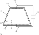
Die spezifische Heizleistung P einer elektrisch beheizbaren Beschichtung mit einem Flächenwiderstand RQuadrat, einer Betriebsspannung U und einem Abstand h zwischen zwei Sammelleitern lässt sich mit der Formel P = U2/(RQuadrat*h2) berechnen. Der Abstand h zwischen zwei Sammelleitern beträgt bei typischen Windschutzscheiben von Personenkraftwagen etwa 0,8 m, was ungefähr der Scheibenhöhe entspricht. Um bei einem Flächenwiderstand von 4 Ohm/Quadrat eine gewünschte spezifische Heizleistung P von 600 W/m2 zu erzielen, ist eine Betriebsspannung U von etwa 40 V notwendig. Da die Bordspannung von Kraftfahrzeugen üblicherweise 14 V beträgt, ist ein Netzteil oder ein Spannungswandler notwendig, um eine Betriebsspannung von 40 V zu erzeugen. Eine Spannungserhöhung von 14 V auf 40 V ist immer mit elektrischen Leitungsverlusten und zusätzlichen Kosten für zusätzliche Bauelemente verbunden.The specific heating power P of an electrically heatable coating with a sheet resistance R square , an operating voltage U and a distance h between two bus bars can be calculated using the formula P = U 2 / (R square * h 2 ). The distance h between two bus bars is about 0.8 m for typical passenger car windshields, which roughly corresponds to the wheel height. In order to achieve a desired specific heating power P of 600 W / m 2 at a sheet resistance of 4 ohms / square, an operating voltage U of approximately 40 V is necessary. Since the on-board voltage of motor vehicles is usually 14 V, is a power supply or voltage transformer is required to produce an operating voltage of 40V. A voltage increase from 14 V to 40 V is always associated with electrical line losses and additional costs for additional components.
Zur Bereitstellung einer ausreichenden spezifischen Heizleistung P, beispielsweise etwa 500 W/m2, insbesondere zur Beheizung größerer Scheiben ist eine weitere Reduzierung des Flächenwiderstands der elektrisch beheizbaren Beschichtung erforderlich. Dies kann bei einer elektrisch beheizbaren Beschichtung mit typischerweise drei Silberlagen durch eine Erhöhung der Dicke der einzelnen Silberschichten erreicht werden. Eine zu große Schichtdicke der Silberschichten führt jedoch zu mangelhaften optischen Eigenschaften der Scheibe, insbesondere im Hinblick auf Transmission und Farbwirkung, so dass gesetzliche Vorschriften, wie sie beispielsweise in ECE R 43 ("Einheitliche Vorschriften für die Genehmigung des Sicherheitsglases und der Verbundglaswerkstoffe") festgelegt sind, nicht eingehalten werden können.To provide a sufficient specific heating power P, for example about 500 W / m 2 , in particular for heating larger windows, a further reduction of the surface resistance of the electrically heatable coating is required. This can be achieved with an electrically heatable coating with typically three silver layers by increasing the thickness of the individual silver layers. Too large layer thickness of the silver layers, however, leads to poor optical properties of the disc, in particular with regard to transmission and color effect, so that statutory provisions, such as in ECE R 43 ("Uniform Rules for the approval of safety glass and laminated glass materials") set are, can not be met.
Der ausreichend geringe Flächenwiderstand kann auch durch die Verwendung von vier Silberlagen in der leitfähigen Beschichtung erreicht werden, wobei die optischen Eigenschaften der Scheibe infolge von geringen Schichtdicken der einzelnen Silberlagen den gesetzlichen Vorgaben entsprechen. Das Aufbringen von Beschichtungen mit vier oder mehr Silberschichten ist jedoch technisch aufwendig und kostenintensiv.The sufficiently low sheet resistance can also be achieved by the use of four silver layers in the conductive coating, wherein the optical properties of the disc due to low layer thicknesses of the individual silver layers comply with the legal requirements. The application of coatings with four or more silver layers, however, is technically complex and costly.
Die Aufgabe der vorliegenden Erfindung besteht darin, eine transparente Scheibe mit verbesserter elektrisch leitfähiger Beschichtung bereitzustellen. Die elektrisch leitfähige Beschichtung soll insbesondere einen im Vergleich zum Stand der Technik geringeren Flächenwiderstand RQuadrat und damit eine verbesserte spezifische Heizleistung P sowie verbesserte reflektierende Eigenschaften für den Infrarotbereich aufweisen. Die Scheibe soll dabei eine hohe Transmission und eine hohe Farbneutralität aufweisen und kostengünstig herstellbar sein.
Die erfindungsgemäße transparente Scheibe umfasst mindestens ein transparentes Substrat und mindestens eine elektrisch leitfähige Beschichtung auf mindestens einer Oberfläche des transparenten Substrats, wobei
- die elektrisch leitfähige Beschichtung mindestens zwei übereinander angeordnete funktionelle Schichten aufweist und jede funktionelle Schicht mindestens
- eine Schicht optisch hochbrechenden Materials mit einem Brechungsindex größer oder gleich 2,1,
- oberhalb der Schicht optisch hochbrechenden Materials eine Glättungsschicht, die zumindest ein nichtkristallines Oxid enthält,
- oberhalb der Glättungsschicht eine erste Anpassungsschicht,
- oberhalb der ersten Anpassungsschicht eine elektrisch leitfähige Schicht und
- oberhalb der elektrisch leitfähigen Schicht eine zweite Anpassungsschicht umfasst,
- die Gesamtschichtdicke aller elektrisch leitfähigen Schichten von 40 nm bis 75 nm beträgt und
- die elektrisch leitfähige Beschichtung einen Flächenwiderstand kleiner 1 Ohm/Quadrat aufweist.
- the electrically conductive coating has at least two functional layers arranged one above the other and each functional layer at least
- a layer of optically high refractive index material having a refractive index greater than or equal to 2.1,
- above the layer of optically high refractive index material a smoothing layer containing at least one non-crystalline oxide,
- above the smoothing layer, a first matching layer,
- above the first matching layer, an electrically conductive layer and
- comprises a second adaptation layer above the electrically conductive layer,
- the total layer thickness of all electrically conductive layers is from 40 nm to 75 nm and
- the electrically conductive coating has a sheet resistance of less than 1 ohm / square.
Ist eine erste Schicht oberhalb einer zweiten Schicht angeordnet, so bedeutet dies im Sinne der Erfindung, dass die erste Schicht weiter vom transparenten Substrat entfernt angeordnet ist als die zweite Schicht. Ist eine erste Schicht unterhalb einer zweiten Schicht angeordnet ist, so bedeutet dies im Sinne der Erfindung, dass die zweite Schicht weiter vom transparenten Substrat entfernt angeordnet ist als die erste Schicht. Die oberste funktionelle Schicht ist diejenige funktionelle Schicht, die den größten Abstand zum transparenten Substrat aufweist. Die unterste funktionelle Schicht ist diejenige funktionelle Schicht, die den geringsten Abstand zum transparenten Substrat aufweist.If a first layer is arranged above a second layer, this means in the sense of the invention that the first layer is arranged further from the transparent substrate than the second layer. If a first layer is arranged below a second layer, this means in the sense of the invention that the second layer is arranged further from the transparent substrate than the first layer. The uppermost functional layer is the functional layer that has the greatest distance from the transparent substrate. The lowest functional layer is the functional layer which has the smallest distance to the transparent substrate.
Eine Schicht im Sinne der Erfindung kann aus einem Material bestehen. Eine Schicht kann aber auch zwei oder mehrere Einzelschichten unterschiedlichen Materials umfassen. Eine erfindungsgemäße funktionelle Schicht umfasst beispielsweise zumindest eine Schicht optisch hochbrechenden Materials, eine Glättungsschicht, eine erste und eine zweite Anpassungsschicht und eine elektrisch leitfähige Schicht.A layer in the sense of the invention may consist of a material. However, a layer may also comprise two or more individual layers of different material. A functional layer according to the invention comprises, for example, at least one layer of optically high-index material, a smoothing layer, a first and a second matching layer and an electrically conductive layer.
Ist eine erste Schicht oberhalb oder unterhalb einer zweiten Schicht angeordnet, so bedeutet dies im Sinne der Erfindung nicht notwendigerweise, dass sich die erste und die zweite Schicht in direktem Kontakt miteinander befinden. Es können eine oder mehrere weitere Schichten zwischen der ersten und der zweiten Schicht angeordnet sein, sofern dies nicht explizit ausgeschlossen wird.If a first layer is arranged above or below a second layer, this does not necessarily mean within the meaning of the invention that the first and the second layer are in direct contact with one another. One or more further layers may be arranged between the first and the second layer, unless this is explicitly excluded.
Die elektrisch leitfähige Beschichtung ist erfindungsgemäß zumindest auf einer Oberfläche des transparenten Substrats aufgebracht. Es können auch beide Oberflächen des transparenten Substrats mit einer erfindungsgemäßen elektrisch leitfähigen Beschichtung versehen sein.The electrically conductive coating is applied according to the invention at least on one surface of the transparent substrate. Both surfaces of the transparent substrate may also be provided with an electrically conductive coating according to the invention.
Die elektrisch leitfähige Beschichtung kann sich über die gesamte Oberfläche des transparenten Substrats erstrecken. Die elektrisch leitfähige Beschichtung kann sich alternativ aber auch nur über einen Teil der Oberfläche des transparenten Substrats erstrecken. Die elektrisch leitfähige Beschichtung erstreckt sich bevorzugt über mindestens 50%, besonders bevorzugt über mindestens 70% und ganz besonders bevorzugt über mindestens 90% der Oberfläche des transparenten Substrats.The electrically conductive coating may extend over the entire surface of the transparent substrate. Alternatively, however, the electrically conductive coating may also extend only over part of the surface of the transparent substrate. The electrically conductive coating preferably extends over at least 50%, more preferably over at least 70% and most preferably over at least 90% of the surface of the transparent substrate.
Die elektrisch leitfähige Beschichtung kann direkt auf der Oberfläche des transparenten Substrats aufgebracht sein. Die elektrisch leitfähige Beschichtung kann alternativ auf eine Trägerfolie aufgebracht sein, die mit dem transparenten Substrat verklebt ist.The electrically conductive coating may be applied directly to the surface of the transparent substrate. The electrically conductive coating may alternatively be applied to a carrier foil which is adhesively bonded to the transparent substrate.
Der besondere Vorteil der Erfindung ergibt sich insbesondere aus den Schichten optisch hochbrechenden Materials innerhalb jeder funktionellen Schicht. Mit optisch hochbrechendem Material wird im Sinne der Erfindung ein Material bezeichnet, dessen Brechungsindex größer oder gleich 2,1 beträgt. Nach dem Stand der Technik sind Schichtfolgen bekannt, bei denen die elektrisch leitfähigen Schichten zwischen jeweils zwei dielektrischen Schichten angeordnet sind. Diese dielektrischen Schichten enthalten üblicherweise Siliziumnitrid. Es hat sich überraschend gezeigt, dass die erfindungsgemäßen Schichten optisch hochbrechenden Materials zu einer Verringerung des Flächenwiderstands der elektrisch leitfähigen Beschichtung führt bei gleichzeitig guten optischen Eigenschaften der transparenten Scheibe, insbesondere hoher Transmission und neutraler Farbwirkung. Zusammen mit den erfindungsgemäßen Glättungsschichten lassen sich durch die Schichten optisch hochbrechenden Materials vorteilhaft geringe Werte für den Flächenwiderstand und damit hohe spezifische Heizleistungen erreichen. Insbesondere können Werte für den Flächenwiderstand erreicht werden, für die nach dem Stand der Technik große Schichtdicken der elektrisch leitfähigen Schichten erforderlich waren, welche die Transmission durch die Scheibe so stark verringern, dass die Erfordernisse an die Transmission von Fahrzeugscheiben nach ECE R 43 nicht erfüllt werden.The particular advantage of the invention results, in particular, from the layers of optically high-index material within each functional layer. With optically high refractive index material is referred to in the context of the invention, a material whose refractive index is greater than or equal to 2.1. In the prior art, layer sequences are known in which the electrically conductive layers are arranged between two respective dielectric layers. These dielectric layers usually contain silicon nitride. It has surprisingly been found that the inventive layers of optically high refractive index material to a reduction of the sheet resistance of the electrically conductive coating leads at the same time good optical properties of the transparent pane, in particular high transmission and neutral color effect. Together with the smoothing layers according to the invention, low values for sheet resistance and thus high specific heating powers can advantageously be achieved by the layers of optically high-index material. In particular, it is possible to achieve values for the sheet resistance for which, according to the prior art, large layer thicknesses of the electrically conductive layers were required, which reduce the transmission through the pane to such an extent that the requirements for the transmission of vehicle windows according to ECE R 43 are not met ,
Die angegebenen Werte für Brechungsindizes sind bei einer Wellenlänge von 550 nm gemessen.The indicated values for refractive indices are measured at a wavelength of 550 nm.
Die erfindungsgemäße transparente Scheibe mit elektrisch leitfähiger Beschichtung weist bevorzugt eine Gesamttransmission von größer 70 % auf. Der Begriff Gesamttransmission bezieht sich auf das durch ECE-R 43, Anhang 3, § 9.1 festgelegte Verfahren zur Prüfung der Lichtdurchlässigkeit von Kraftfahrzeugscheiben.The transparent pane according to the invention with an electrically conductive coating preferably has a total transmission of greater than 70%. The term total transmission refers to the procedure defined by ECE-R 43, Annex 3, § 9.1 for testing the light transmission of vehicle windows.
Die elektrisch leitfähige Beschichtung weist erfindungsgemäß einen Flächenwiderstand von kleiner 1 Ohm/Quadrat auf. Der Flächenwiderstand der elektrisch leitfähigen Beschichtung beträgt bevorzugt von 0,4 Ohm/Quadrat bis 0,9 Ohm/Quadrat, besonders bevorzugt von 0,5 Ohm/Quadrat bis 0,8 Ohm/Quadrat, beispielsweise etwa 0,7 Ohm/Quadrat. In diesem Bereich für den Flächenwiderstand werden vorteilhaft hohe spezifische Heizleistungen P erreicht. Außerdem weist die elektrisch leitfähige Beschichtung in diesem Bereich für den Flächenwiderstand besonders gute reflektierende Eigenschaften für den Infrarotbereich auf.The electrically conductive coating has, according to the invention, a sheet resistance of less than 1 ohm / square. The sheet resistance of the electrically conductive coating is preferably from 0.4 ohms / square to 0.9 ohms / square, more preferably from 0.5 ohms / square to 0.8 ohms / square, for example, about 0.7 ohms / square. In this area for sheet resistance advantageously high specific heat outputs P can be achieved. In addition, the electrically conductive coating in this area for sheet resistance particularly good reflective properties for the infrared range.
Zur Erhöhung der Gesamttransmission und / oder zur Verringerung des Flächenwiderstands kann die transparente Scheibe mit elektrisch leitfähiger Beschichtung einer Temperaturbehandlung, beispielsweise bei einer Temperatur von 500 °C bis 700 °C, unterzogen werden.To increase the overall transmission and / or to reduce the surface resistance, the transparent pane with an electrically conductive coating can be subjected to a temperature treatment, for example at a temperature of 500 ° C. to 700 ° C.
Es hat sich gezeigt, dass die erfindungsgemäße elektrisch leitfähige Beschichtung einer solchen Temperaturbehandlung unterzogen werden kann, ohne dass die Beschichtung beschädigt wird. Die erfindungsgemäße transparente Scheibe kann zudem konvex oder konkav gebogen werden, ohne dass die Beschichtung beschädigt wird. Das sind große Vorteile der erfindungsgemäßen elektrisch leitfähigen Beschichtung.It has been found that the electrically conductive coating according to the invention can be subjected to such a temperature treatment without the coating being damaged. The transparent pane according to the invention can also be bent convexly or concavely without damaging the coating. These are great advantages of the electrically conductive coating according to the invention.
In einer bevorzugten Ausführung der Erfindung weist die elektrisch leitfähige Beschichtung drei funktionelle Schichten auf. Eine technisch aufwendige und kostenintensive Herstellung einer elektrisch leitfähigen Beschichtung mit vier oder mehr elektrisch leitfähigen Schichten kann somit vermieden werden.In a preferred embodiment of the invention, the electrically conductive coating has three functional layers. A technically complex and cost-intensive production of an electrically conductive coating with four or more electrically conductive layers can thus be avoided.
Die Schicht optisch hochbrechenden Materials weist bevorzugt einen Brechungsindex n von 2,1 bis 2,5 auf, besonders bevorzugt von 2,1 bis 2,3.The layer of optically high-index material preferably has a refractive index n of 2.1 to 2.5, more preferably of 2.1 to 2.3.
Die Schicht optisch hochbrechenden Materials enthält erfindungsgemäß zumindest ein Silizium-Metall-Mischnitrid, bevorzugt Silizium-Zirkonium-Mischnitrid. Das ist besonders vorteilhaft im Hinblick auf den Flächenwiderstand der elektrisch leitfähigen Beschichtung. Das Silizium-Zirkonium-Mischnitrid weist bevorzugt Dotierungen auf. Die Schicht optisch hochbrechenden Materials kann beispielsweise ein Aluminium-dotiertes Silizium-Zirkonium-Mischnitrid (SiZrNx:Al) enthalten.According to the invention, the layer of optically high refractive index material contains at least one silicon-metal mixed nitride, preferably silicon-zirconium mixed nitride. This is particularly advantageous with regard to the sheet resistance of the electrically conductive coating. The silicon-zirconium mixed nitride preferably has dopants. The layer of optically high refractive index material may, for example, contain an aluminum-doped mixed silicon-zirconium mixed nitride (SiZrN x : Al).
Das Silizium-Zirkonium-Mischnitrid wird bevorzugt mittels magnetfeldunterstützter Kathodenzerstäubung mit einem Target abgeschieden, welches von 40 Gew. % bis 70 Gew. % Silizium, von 30 Gew. % bis 60 Gew. % Zirkonium und von 0 Gew. % bis 10 Gew. % Aluminium sowie herstellungsbedingte Beimengungen enthält. Das Target enthält besonders bevorzugt von 45 Gew. % bis 60 Gew. % Silizium, von 35 Gew. % bis 55 Gew. % Zirkonium und von 3 Gew. % bis 8 Gew. % Aluminium sowie herstellungsbedingte Beimengungen. Die Abscheidung des Silizium-Zirkonium-Mischnitrids erfolgt bevorzugt unter Zugabe von Stickstoff als Reaktionsgas während der Kathodenzerstäubung.The silicon-zirconium mixed nitride is preferably deposited by means of magnetic field-assisted cathode sputtering with a target which comprises from 40% by weight to 70% by weight of silicon, from 30% by weight to 60% by weight of zirconium and from 0% by weight to 10% by weight. Contains% aluminum and production-related admixtures. The target particularly preferably contains from 45% by weight to 60% by weight of silicon, from 35% by weight to 55% by weight of zirconium and from 3% by weight to 8% by weight of aluminum, and admixtures resulting from production. The deposition of the silicon-zirconium mixed nitride is preferably carried out with the addition of nitrogen as the reaction gas during the cathode sputtering.
Die Schicht optisch hochbrechenden Materials kann aber auch beispielsweise zumindest Silizium-Aluminium-Mischnitrid, Silizium-Hafnium-Mischnitrid oder Silizium-Titan-Mischnitrid enthalten. Die Schicht optisch hochbrechenden Materials kann alternativ beispielsweise MnO, WO3, Nb2O5, Bi2O3, TiO2, Zr3N4 und / oder AIN enthalten.However, the layer of optically high-refractive index material may also contain, for example, at least silicon-aluminum mixed nitride, mixed silicon-hafnium nitride or mixed silicon-titanium nitride. The layer of optically high refractive index material can Alternatively, for example, MnO, WO 3 , Nb 2 O 5 , Bi 2 O 3 , TiO 2 , Zr 3 N 4 and / or AIN contain.
Die Schichtdicke jeder Schicht optisch hochbrechenden Materials, die zwischen zwei elektrisch leitfähigen Schichten angeordnet ist, beträgt bevorzugt von 35 nm bis 70 nm, besonders bevorzugt von 45 nm bis 60 nm. In diesem Bereich für die Schichtdicke werden besonders vorteilhafte Flächenwiderstände der elektrisch leitfähigen Beschichtung und besonders gute optische Eigenschaften der transparenten Scheibe erreicht. Eine Schicht optisch hochbrechenden Materials ist im Sinne der Erfindung zwischen zwei elektrisch leitfähigen Schichten angeordnet, wenn zumindest eine elektrisch leitfähige Schicht oberhalb der Schicht optisch hochbrechenden Materials und wenn zumindest eine elektrisch leitfähige Schicht unterhalb der Schicht optisch hochbrechenden Materials angeordnet ist. Die Schicht optisch hochbrechenden Materials steht aber erfindungsgemäß nicht in direktem Kontakt zu den benachbarten elektrisch leitfähigen Schichten.The layer thickness of each layer of optically high-index material, which is arranged between two electrically conductive layers, is preferably from 35 nm to 70 nm, more preferably from 45 nm to 60 nm. In this range for the layer thickness are particularly advantageous surface resistances of the electrically conductive coating and achieved particularly good optical properties of the transparent pane. A layer of optically high refractive index material is arranged in the sense of the invention between two electrically conductive layers, if at least one electrically conductive layer is arranged above the layer of optically high refractive index material and if at least one electrically conductive layer is arranged below the layer of optically high refractive index material. However, according to the invention, the layer of optically high refractive index material is not in direct contact with the adjacent electrically conductive layers.
Die Schichtdicke der untersten Schicht optisch hochbrechenden Materials beträgt bevorzugt von 20 nm bis 40 nm. Damit werden besonders gute Ergebnisse erzielt.The layer thickness of the lowermost layer of optically high-index material is preferably from 20 nm to 40 nm. This results in particularly good results.
In einer vorteilhaften Ausgestaltung der Erfindung ist oberhalb der obersten funktionellen Schicht eine Abdeckschicht angeordnet. Die Abdeckschicht schützt die darunter angeordneten Schichten vor Korrosion. Die Abdeckschicht ist bevorzugt dielektrisch. Die Abdeckschicht kann beispielsweise Siliziumnitrid und / oder Zinnoxid enthalten.In an advantageous embodiment of the invention, a covering layer is arranged above the uppermost functional layer. The cover protects the underlying layers from corrosion. The cover layer is preferably dielectric. The cover layer may contain, for example, silicon nitride and / or tin oxide.
Die Abdeckschicht enthält bevorzugt zumindest ein optisch hochbrechendes Material mit einem Brechungsindex größer oder gleich 2,1. Die Abdeckschicht enthält besonders bevorzugt zumindest ein Silizium-Metall-Mischnitrid, insbesondere Silizium-Zirkonium-Mischnitrid, wie Aluminium-dotiertes Silizium-Zirkonium-Mischnitrid. Das ist besonders vorteilhaft im Hinblick auf die optischen Eigenschaften der erfindungsgemäßen transparenten Scheibe. Die Abdeckschicht kann aber auch andere Silizium-Metall-Mischnitride enthalten, beispielsweise Silizium-Aluminium-Mischnitrid, Silizium-Hafnium-Mischnitrid oder Silizium-Titan-Mischnitrid. Die Abdeckschicht kann alternativ auch beispielsweise MnO, WO3, Nb2O5, Bi2O3, TiO2, Zr3N4 und / oder AIN enthalten.The cover layer preferably contains at least one optically high refractive index material having a refractive index greater than or equal to 2.1. The cover layer particularly preferably comprises at least one mixed silicon-metal nitride, in particular mixed silicon-zirconium mixed nitride, such as aluminum-doped mixed silicon-zirconium nitride. This is particularly advantageous with regard to the optical properties of the transparent pane according to the invention. However, the cover layer can also contain other silicon-metal mixed nitrides, for example silicon-aluminum mixed nitride, silicon-hafnium mixed nitride or silicon-titanium mixed nitride. The cover layer may alternatively also contain, for example, MnO, WO 3 , Nb 2 O 5 , Bi 2 O 3 , TiO 2 , Zr 3 N 4 and / or AIN.
Die Schichtdicke der Abdeckschicht beträgt bevorzugt von 20 nm bis 40 nm. Damit werden besonders gute Ergebnisse erzielt.The layer thickness of the cover layer is preferably from 20 nm to 40 nm. This results in particularly good results.
Jede funktionelle Schicht der elektrisch leitfähigen Beschichtung umfasst erfindungsgemäß zumindest eine Glättungsschicht. Die Glättungsschicht ist unterhalb der ersten Anpassungsschicht angeordnet, bevorzugt zwischen der Schicht optisch hochbrechenden Materials und der ersten Anpassungsschicht. Die Glättungsschicht steht bevorzugt in direktem Kontakt zur ersten Anpassungsschicht. Die Glättungsschicht bewirkt eine Optimierung, insbesondere Glättung der Oberfläche für eine anschließend oberhalb aufgebrachte elektrisch leitfähige Schicht. Eine auf eine glattere Oberfläche abgeschiedene elektrisch leitfähige Schicht weist einen höheren Transmissionsgrad bei einem gleichzeitig niedrigeren Flächenwiderstand auf.Each functional layer of the electrically conductive coating comprises according to the invention at least one smoothing layer. The smoothing layer is arranged below the first matching layer, preferably between the layer of optically high-refractive index material and the first matching layer. The smoothing layer is preferably in direct contact with the first matching layer. The smoothing layer effects an optimization, in particular smoothing of the surface for a subsequently applied electrically conductive layer. An electrically conductive layer deposited on a smoother surface has a higher transmittance with a simultaneously lower surface resistance.
Die Glättungsschicht enthält erfindungsgemäß zumindest ein nichtkristallines Oxid. Das Oxid kann amorph oder teilamorph (und damit teilkristallin) sein, ist aber nicht vollständig kristallin. Die nichtkristalline Glättungsschicht weist eine geringe Rauheit auf und bildet somit eine vorteilhaft glatte Oberfläche für die oberhalb der Glättungsschicht aufzubringenden Schichten. Die nichtkristalline Glättungsschicht bewirkt weiter eine verbesserte Oberflächenstruktur der direkt oberhalb der Glättungsschicht abgeschiedenen Schicht, welche bevorzugt die erste Anpassungsschicht ist. Die Glättungsschicht kann beispielsweise zumindest ein Oxid eines oder mehrerer der Elemente Zinn, Silizium, Titan, Zirkonium, Hafnium, Zink, Gallium und Indium enthalten.The smoothing layer according to the invention contains at least one non-crystalline oxide. The oxide may be amorphous or partially amorphous (and thus partially crystalline) but is not completely crystalline. The non-crystalline smoothing layer has a low roughness and thus forms an advantageously smooth surface for the layers to be applied above the smoothing layer. The non-crystalline smoothing layer further effects an improved surface structure of the layer deposited directly above the smoothing layer, which is preferably the first matching layer. The smoothing layer may contain, for example, at least one oxide of one or more of the elements tin, silicon, titanium, zirconium, hafnium, zinc, gallium and indium.
Die Glättungsschicht enthält bevorzugt ein nichtkristallines Mischoxid. Die Glättungsschicht enthält ganz besonders bevorzugt ein Zinn-Zink-Mischoxid. Das Mischoxid kann Dotierungen aufweisen. Die Glättungsschicht kann beispielsweise ein Antimon-dotiertes Zinn-Zink-Mischoxid (SnZnOx:Sb) enthalten. Das Mischoxid weist bevorzugt einen unterstöchiometrischen Sauerstoffgehalt auf. Ein Verfahren zur Herstellung von Zinn-Zink-Mischoxid-Schichten durch reaktive Kathodenzerstäubung ist beispielsweise aus
Die Schichtdicke einer Glättungsschicht beträgt bevorzugt von 3 nm bis 20 nm besonders bevorzugt von 4 nm bis 12 nm. Die Glättungsschicht weist bevorzugt einen Brechungsindex von kleiner als 2,2 auf.The layer thickness of a smoothing layer is preferably from 3 nm to 20 nm, particularly preferably from 4 nm to 12 nm. The smoothing layer preferably has a refractive index of less than 2.2.
Die elektrisch leitfähige Schicht enthält bevorzugt zumindest ein Metall, beispielsweise Gold oder Kupfer, oder eine Legierung, besonders bevorzugt Silber oder eine silberhaltige Legierung. Die elektrisch leitfähige Schicht kann aber auch andere, dem Fachmann bekannte elektrisch leitfähige Materialen enthalten.The electrically conductive layer preferably contains at least one metal, for example gold or copper, or an alloy, particularly preferably silver or a silver-containing alloy. However, the electrically conductive layer may also contain other electrically conductive materials known to those skilled in the art.
In einer vorteilhaften Ausgestaltung der Erfindung enthält die elektrisch leitfähige Schicht mindestens 90 Gew. % Silber, bevorzugt mindestens 99,9 Gew. % Silber. Die elektrisch leitfähige Schicht wird bevorzugt mit gängigen Verfahren zur Schichtabscheidung von Metallen, beispielsweise durch Vakuumverfahren wie die magnetfeldunterstützte Kathodenzerstäubung aufgebracht.In an advantageous embodiment of the invention, the electrically conductive layer contains at least 90% by weight of silver, preferably at least 99.9% by weight of silver. The electrically conductive layer is preferably applied using conventional methods for the layer deposition of metals, for example by vacuum methods such as magnetic field-assisted sputtering.
Die elektrisch leitfähige Schicht weist bevorzugt eine Schichtdicke von 8 nm bis 25 nm, besonders bevorzugt von 10 nm bis 20 nm auf. Das ist besonders vorteilhaft im Hinblick auf die Transparenz und den Flächenwiderstand der elektrisch leitfähigen Schicht.The electrically conductive layer preferably has a layer thickness of 8 nm to 25 nm, particularly preferably from 10 nm to 20 nm. This is particularly advantageous with regard to the transparency and the sheet resistance of the electrically conductive layer.
Die Gesamtschichtdicke aller elektrisch leitfähigen Schichten beträgt erfindungsgemäß von 40 nm bis 75 nm. In diesem Bereich für die Gesamtdicke aller elektrisch leitfähigen Schichten wird bei für Fahrzeugscheiben, insbesondere Windschutzscheiben typischen Abständen h zwischen zwei Sammelleitern und einer Betriebsspannung U im Bereich von 12 V bis 15 V vorteilhaft eine ausreichend hohe spezifische Heizleistung P und gleichzeitig eine ausreichend hohe Transmission erreicht. Zudem weist die elektrisch leitfähige Beschichtung in diesem Bereich für die Gesamtdicke aller elektrisch leitfähigen Schichten besonders gute reflektierende Eigenschaften für den Infrarotbereich auf. Zu geringere Gesamtschichtdicken aller elektrisch leitfähigen Schichten ergeben einen zu hohen Flächenwiderstand RQuadrat und damit eine zu geringe spezifische Heizleistung P sowie verringerte reflektierende Eigenschaften für den Infrarotbereich. Zu große Gesamtschichtdicken aller elektrisch leitfähigen Schichten verringern die Transmission durch die Scheibe zu stark, so dass die Erfordernisse an die Transmission von Fahrzeugscheiben nach ECE R 43 nicht erfüllt werden. Es hat sich gezeigt, dass besonders gute Ergebnisse mit einer Gesamtschichtdicke aller elektrisch leitfähigen Schichten von 50 nm bis 60 nm, insbesondere von 51 nm bis 58 nm erzielt werden. Das ist besonders vorteilhaft im Hinblick auf den Flächenwiderstand der elektrisch leitfähigen Beschichtung und die Transmission der transparenten Scheibe.The total layer thickness of all electrically conductive layers is according to the invention from 40 nm to 75 nm. In this range for the total thickness of all electrically conductive layers is typical for vehicle windows, especially windshields h between two buses and an operating voltage U in the range of 12 V to 15 V. advantageously achieves a sufficiently high specific heating power P and at the same time a sufficiently high transmission. In addition, the electrically conductive coating in this area has particularly good reflective properties for the infrared range for the total thickness of all electrically conductive layers. To lower total layer thicknesses of all electrically conductive layers result in too high sheet resistance R square and thus one too low specific heating power P as well as reduced reflective properties for the infrared range. Too large total layer thicknesses of all electrically conductive layers reduce the transmission through the disc too strong, so that the requirements for the transmission of vehicle windows according to ECE R 43 are not met. It has been shown that particularly good results are achieved with a total layer thickness of all electrically conductive layers of 50 nm to 60 nm, in particular from 51 nm to 58 nm. This is particularly advantageous with regard to the sheet resistance of the electrically conductive coating and the transmission of the transparent pane.
Die erste Anpassungsschicht und / oder die zweite Anpassungsschicht enthält bevorzugt Zinkoxid ZnO1-δ mit 0 ≤ δ ≤ 0,01, beispielsweise Aluminium-dotiertes Zinkoxid (ZnO:Al). Das Zinkoxid wird bevorzugt unterstöchiometrisch bezüglich des Sauerstoffs abgeschieden um eine Reaktion von überschüssigem Sauerstoff mit der silberhaltigen Schicht zu vermeiden. Die Zinkoxid-Schicht wird bevorzugt durch magnetfeldunterstützte Kathodenzerstäubung abgeschieden. Das Target enthält bevorzugt von 85 Gew. % bis 100 Gew. % Zinkoxid und von 0 Gew. % bis 15 Gew. % Aluminium sowie herstellungsbedingte Beimengungen. Das Target enthält besonders bevorzugt von 90 Gew. % bis 95 Gew. % Zinkoxid und von 5 Gew. % bis 10 Gew. % Aluminium sowie herstellungsbedingte Beimengungen. Das Target enthält alternativ bevorzugt von 95 Gew.-% bis 99 Gew.-% Zink und von 1 Gew.-% bis 5 Gew.-% Aluminium, wobei die Abscheidung der Schichten unter Zugabe von Sauerstoff als Reaktionsgas erfolgt. Die Schichtdicken der ersten Anpassungsschicht und der zweiten Anpassungsschicht betragen bevorzugt von 3 nm bis 20 nm besonders bevorzugt von 4 nm bis 12 nm.The first matching layer and / or the second matching layer preferably contains zinc oxide ZnO 1-δ with 0 ≦ δ ≦ 0.01, for example aluminum-doped zinc oxide (ZnO: Al). The zinc oxide is preferably deposited substoichiometrically with respect to the oxygen in order to avoid a reaction of excess oxygen with the silver-containing layer. The zinc oxide layer is preferably deposited by magnetic field assisted sputtering. The target preferably contains from 85% by weight to 100% by weight of zinc oxide and from 0% by weight to 15% by weight of aluminum, as well as by production-related admixtures. The target contains particularly preferably from 90% by weight to 95% by weight of zinc oxide and from 5% by weight to 10% by weight of aluminum, as well as production-related admixtures. Alternatively, the target preferably contains from 95% by weight to 99% by weight of zinc and from 1% by weight to 5% by weight of aluminum, the deposition of the layers taking place with the addition of oxygen as the reaction gas. The layer thicknesses of the first matching layer and the second matching layer are preferably from 3 nm to 20 nm, particularly preferably from 4 nm to 12 nm.
In einer vorteilhaften Ausgestaltung der erfindungsgemäßen transparenten Scheibe umfasst zumindest eine funktionelle Schicht zumindest eine Blockerschicht. Die Blockerschicht steht in direktem Kontakt zur elektrisch leitfähigen Schicht und ist unmittelbar oberhalb oder unmittelbar unterhalb der elektrisch leitfähigen Schicht angeordnet. Zwischen der elektrisch leitfähigen Schicht und der Blockerschicht ist also keine weitere Schicht angeordnet. Die funktionelle Schicht kann auch zwei Blockerschichten umfassen, wobei bevorzugt eine Blockerschicht unmittelbar oberhalb und eine Blockerschicht unmittelbar unterhalb der elektrisch leitfähigen Schicht angeordnet ist. Besonders bevorzugt umfasst jede funktionelle Schicht zumindest eine solche Blockerschicht. Die Blockerschicht enthält bevorzugt Niob, Titan, Nickel, Chrom und / oder Legierungen davon, besonders bevorzugt Nickel-Chrom-Legierungen. Die Schichtdicke der Blockerschicht beträgt bevorzugt von 0,1 nm bis 2 nm. Damit werden gute Ergebnisse erzielt. Eine Blockerschicht unmittelbar unterhalb der elektrisch leitfähigen Schicht dient insbesondere zur Stabilisierung der elektrisch leitfähigen Schicht während einer Temperaturbehandlung und verbessert die optische Qualität der elektrisch leitfähigen Beschichtung. Eine Blockerschicht unmittelbar oberhalb der elektrisch leitfähigen Schicht verhindert den Kontakt der empfindlichen elektrisch leitfähigen Schicht mit der oxidierenden reaktiven Atmosphäre während der Abscheidung der folgenden Schicht durch reaktive Kathodenzerstäubung, beispielsweise der zweiten Anpassungsschicht, welche bevorzugt Zinkoxid enthält.In an advantageous embodiment of the transparent pane according to the invention, at least one functional layer comprises at least one blocking layer. The blocker layer is in direct contact with the electrically conductive layer and is arranged directly above or immediately below the electrically conductive layer. Thus, no further layer is arranged between the electrically conductive layer and the blocking layer. The functional layer can also comprise two blocking layers, wherein preferably a blocking layer is arranged immediately above and a blocking layer is arranged immediately below the electrically conductive layer. Particularly preferably, each functional layer comprises at least one such blocker layer. The blocking layer preferably contains niobium, titanium, nickel, chromium and / or alloys thereof, particularly preferably nickel-chromium alloys. The layer thickness of the blocking layer is preferably from 0.1 nm to 2 nm. This results in good results. A blocking layer immediately below the electrically conductive layer serves in particular to stabilize the electrically conductive layer during a temperature treatment and improves the optical quality of the electrically conductive coating. A blocking layer immediately above the electrically conductive layer prevents contact of the sensitive electrically conductive layer with the oxidizing reactive atmosphere during the deposition of the following layer by reactive sputtering, for example the second matching layer, which preferably contains zinc oxide.
Blockerschichten beispielsweise auf der Basis von Titan oder Nickel-Chrom-Legierungen sind nach dem Stand der Technik an sich bekannt. Typischerweise werden Blockerschichten mit einer Dicke von etwa 0,5 nm oder sogar einiger Nanometer verwendet. Es hat sich überraschend gezeigt, dass die erfindungsgemäße Ausgestaltung der elektrisch leitfähigen Beschichtung zu einer verminderten Anfälligkeit der Beschichtung für Defekte, die beispielsweise durch Korrosion oder Oberflächendefekte des transparenten Substrats hervorgerufen werden, führt. Daher können in der erfindungsgemäßen elektrisch leitfähigen Beschichtung Blockerschichten mit einer deutlich reduzierten Schichtdicke verwendet werden. Der besondere Vorteil von besonders dünnen Blockerschichten liegt in einer höheren Transmission und Farbneutralität der erfindungsgemäßen transparenten Scheibe mit elektrisch leitfähiger Beschichtung sowie in geringeren Herstellungskosten. Besonders gute Ergebnisse werden mit einer Schichtdicke der Blockerschichten von 0,1 nm bis 0,5 nm, bevorzugt von 0,1 nm bis 0,3 nm, insbesondere von 0,2 nm bis 0,3 nm erreicht.Blocker layers, for example based on titanium or nickel-chromium alloys, are known per se in the prior art. Typically, blocking layers having a thickness of about 0.5 nm or even a few nanometers are used. It has surprisingly been found that the inventive design of the electrically conductive coating leads to a reduced susceptibility of the coating to defects caused, for example, by corrosion or surface defects of the transparent substrate. Therefore blocker layers with a significantly reduced layer thickness can be used in the electrically conductive coating according to the invention. The particular advantage of particularly thin blocking layers lies in a higher transmission and color neutrality of the transparent pane according to the invention with an electrically conductive coating and in lower production costs. Particularly good results are achieved with a layer thickness of the blocking layers of 0.1 nm to 0.5 nm, preferably from 0.1 nm to 0.3 nm, in particular from 0.2 nm to 0.3 nm.
Das transparente Substrat enthält bevorzugt Glas, besonders bevorzugt Flachglas, Floatglas, Quarzglas, Borosilikatglas, Kalk-Natron-Glas oder klare Kunststoffe, vorzugsweise starre klare Kunststoffe, insbesondere Polyethylen, Polypropylen, Polycarbonat, Polymethylmethacrylat, Polystyrol, Polyamid, Polyester, Polyvinylchlorid und / oder Gemische davon. Beispiele geeigneter Gläser sind aus
Die Dicke des transparenten Substrats kann breit variieren und so hervorragend den Erfordernissen im Einzelfall angepasst werden. Vorzugsweise werden Scheiben mit den Standardstärken von 1,0 mm bis 25 mm und bevorzugt von 1,4 mm bis 2,6 mm verwendet. Die Größe des transparenten Substrats kann breit variieren und richtet sich nach der erfindungsgemäßen Verwendung. Das transparente Substrat weist beispielsweise im Fahrzeugbau und Architekturbereich übliche Flächen von 200 cm2 bis zu 4 m2 auf.The thickness of the transparent substrate can vary widely and thus be perfectly adapted to the requirements in individual cases. It is preferable to use disks having the standard thicknesses of 1.0 mm to 25 mm, and preferably 1.4 mm to 2.6 mm. The size of the transparent substrate can vary widely and depends on the use according to the invention. The transparent substrate has, for example, in vehicle construction and architecture area common areas of 200 cm 2 to 4 m 2 .
Das transparente Substrat kann eine beliebige dreidimensionale Form aufweisen. Vorzugsweise hat die dreidimensionale Form keine Schattenzonen, so dass sie beispielsweise durch Kathodenzerstäubung beschichtet werden kann. Das transparente Substrat ist bevorzugt plan oder leicht oder stark in einer Richtung oder in mehreren Richtungen des Raumes gebogen. Das transparente Substrat kann farblos oder gefärbt sein.The transparent substrate may have any three-dimensional shape. Preferably, the three-dimensional shape has no shadow zones, so that it can be coated, for example, by sputtering. The transparent substrate is preferably planar or slightly curved in one direction or in several directions of the space. The transparent substrate may be colorless or colored.
In einer vorteilhaften Ausgestaltung der Erfindung ist das transparente Substrat über zumindest eine thermoplastische Zwischenschicht mit einer zweiten Scheibe zu einer Verbundscheibe verbunden. Die erfindungsgemäße elektrisch leitfähige Beschichtung ist bevorzugt auf die der thermoplastischen Zwischenschicht zugewandten Oberfläche des transparenten Substrats aufgebracht. Dadurch wird die elektrisch leitfähige Beschichtung vorteilhaft vor Beschädigungen und Korrosion geschützt.In an advantageous embodiment of the invention, the transparent substrate is connected via at least one thermoplastic intermediate layer to a second pane to form a composite pane. The electrically conductive coating according to the invention is preferably applied to the surface of the transparent substrate facing the thermoplastic intermediate layer. As a result, the electrically conductive coating is advantageously protected against damage and corrosion.
Die Verbundscheibe weist bevorzugt eine Gesamttransmission von größer 70 % auf.The composite disk preferably has a total transmission of greater than 70%.
Die thermoplastische Zwischenschicht enthält bevorzugt thermoplastische Kunststoffe, beispielsweise Polyvinylbutyral (PVB), Ethylenvinylacetat (EVA), Polyurethan (PU), Polyethylenterephthalat (PET) oder mehrere Schichten davon, bevorzugt mit Dicken von 0,3 mm bis 0,9 mm.The thermoplastic intermediate layer preferably contains thermoplastics, for example polyvinyl butyral (PVB), ethylene vinyl acetate (EVA), polyurethane (PU), polyethylene terephthalate (PET) or several layers thereof, preferably with thicknesses of 0.3 mm to 0.9 mm.
Die zweite Scheibe enthält bevorzugt Glas, besonders bevorzugt Flachglas, Floatglas, Quarzglas, Borosilikatglas, Kalk-Natron-Glas oder klare Kunststoffe, vorzugsweise starre klare Kunststoffe, insbesondere Polyethylen, Polypropylen, Polycarbonat, Polymethylmethacrylat, Polystyrol, Polyamid, Polyester, Polyvinylchlorid und / oder Gemische davon. Die zweite Scheibe weist bevorzugt eine Dicke von 1,0 mm bis 25 mm und besonders bevorzugt von 1,4 mm bis 2,6 mm auf.The second pane preferably contains glass, particularly preferably flat glass, float glass, quartz glass, borosilicate glass, soda-lime glass or clear plastics, preferably rigid clear plastics, in particular polyethylene, polypropylene, polycarbonate, polymethyl methacrylate, polystyrene, polyamide, polyester, polyvinyl chloride and / or Mixtures thereof. The second pane preferably has a thickness of 1.0 mm to 25 mm and more preferably 1.4 mm to 2.6 mm.
Die elektrisch leitfähige Beschichtung erstreckt sich bevorzugt über die gesamte Oberfläche des transparenten Substrats, abzüglich eines umlaufenden rahmenförmigen beschichtungsfreien Bereichs mit einer Breite von 2 mm bis 20 mm, bevorzugt von 5 mm bis 10 mm. Der beschichtungsfreie Bereich wird bevorzugt durch die thermoplastische Zwischenschicht oder einen Acrylatkleber als Dampfdiffusionssperre hermetisch versiegelt. Durch die Dampfdiffusionssperre wird die korrosionsempfindliche elektrisch leitfähige Beschichtung vor Feuchtigkeit und Luftsauerstoff geschützt. Ist die Verbundscheibe als Fahrzeugscheibe, beispielsweise als Windschutzscheibe vorgesehen und wird die elektrisch leitfähige Beschichtung als elektrisch beheizbare Beschichtung verwendet, so bewirkt der umlaufende beschichtungsfreie Bereich zudem eine elektrische Isolierung zwischen der spannungsführenden Beschichtung und der Fahrzeugkarosserie.The electrically conductive coating preferably extends over the entire surface of the transparent substrate, minus a circumferential frame-shaped coating-free region having a width of 2 mm to 20 mm, preferably of 5 mm to 10 mm. The coating-free region is preferably hermetically sealed by the thermoplastic intermediate layer or an acrylate adhesive as a vapor diffusion barrier. The vapor diffusion barrier protects the corrosion-sensitive, electrically conductive coating from moisture and atmospheric oxygen. If the composite pane is provided as a vehicle pane, for example as a windscreen, and if the electrically conductive coating is used as an electrically heatable coating, then the circumferential coating-free area additionally effects an electrical insulation between the live coating and the vehicle body.
Das transparente Substrat kann in zumindest einem weiteren Bereich beschichtungsfrei sein, der beispielsweise als Datenübertragungsfenster oder Kommunikationsfenster dient. Die transparente Scheibe ist in dem weiteren beschichtungsfreien Bereich für elektromagnetische und insbesondere infrarote Strahlung durchlässig.The transparent substrate can be coating-free in at least one further area, which serves, for example, as a data transmission window or communication window. The transparent pane is transparent in the further coating-free area for electromagnetic and in particular infrared radiation.
Die elektrisch leitfähige Beschichtung kann direkt auf der Oberfläche des transparenten Substrats aufgebracht sein. Alternativ kann die elektrisch leitfähige Beschichtung auf eine Trägerfolie aufgebracht sein, die zwischen zwei Zwischenschichten eingebettet ist. Die Trägerfolie enthält bevorzugt ein thermoplastisches Polymer, insbesondere Polyvinylbutyral (PVB), Ethylenvinylacetat (EVA), Polyurethan (PU), Polyethylenterephthalat (PET) oder Kombinationen davon.The electrically conductive coating may be applied directly to the surface of the transparent substrate. Alternatively, the electrically conductive coating may be applied to a carrier foil which is embedded between two intermediate layers. The carrier film preferably contains a thermoplastic polymer, in particular polyvinyl butyral (PVB), ethylene vinyl acetate (EVA), polyurethane (PU), polyethylene terephthalate (PET) or combinations thereof.
Das transparente Substrat kann beispielsweise auch mit einer zweiten Scheibe über Abstandshalter zu einer Isolierverglasung verbunden sein. Das transparente Substrat kann auch mit mehr als einer weiteren Scheibe über thermoplastische Zwischenschichten und / oder Abstandshalter verbunden sein. Ist das transparente Substrat mit einer oder mit mehreren weiteren Scheiben verbunden, so kann eine oder mehrere dieser weiteren Scheiben ebenfalls eine elektrisch leitfähige Beschichtung aufweisen.The transparent substrate may for example also be connected to a second pane via spacers to form an insulating glazing. The transparent substrate can also be connected to more than one further pane via thermoplastic intermediate layers and / or spacers. If the transparent substrate is connected to one or more further disks, then one or more of these further disks may also have an electrically conductive coating.
In einer bevorzugten Ausgestaltung ist die erfindungsgemäße elektrisch leitfähige Beschichtung eine elektrisch beheizbare Beschichtung. Die elektrisch leitfähige Beschichtung ist dabei geeignet elektrisch kontaktiert.In a preferred embodiment, the electrically conductive coating according to the invention is an electrically heatable coating. The electrically conductive coating is suitably electrically contacted.
In einer weiteren bevorzugten Ausgestaltung ist die erfindungsgemäße elektrisch leitfähige Beschichtung eine Beschichtung mit reflektierenden Eigenschaften für den Infrarotbereich. Die elektrisch leitfähige Beschichtung muss dazu nicht elektrisch kontaktiert sein. Als Beschichtung mit reflektierenden Eigenschaften für den Infrarotbereich ist im Sinne der Erfindung insbesondere eine Beschichtung zu verstehen, welche einen Reflexionsgrad von mindestens 20 % im Wellenlängenbereich von 1000 nm bis 1600 nm aufweist. Bevorzugt weist die erfindungsgemäße elektrisch leitfähige Beschichtung einen Reflexionsgrad von größer oder gleich 50 % im Wellenlängenbereich von 1000 nm bis 1600 nm auf.In a further preferred embodiment, the electrically conductive coating according to the invention is a coating with reflective properties for the infrared range. The electrically conductive coating does not have to be contacted electrically. For the purposes of the invention, a coating with reflective properties for the infrared range is to be understood in particular to mean a coating which has a reflectance of at least 20% in the wavelength range from 1000 nm to 1600 nm. The electrically conductive coating according to the invention preferably has a reflectance of greater than or equal to 50% in the wavelength range from 1000 nm to 1600 nm.
In einer vorteilhaften Ausgestaltung der Erfindung ist die elektrisch leitfähige Beschichtung über Sammelleiter mit einer Spannungsquelle verbunden und eine an die elektrisch leitfähige Beschichtung angelegte Spannung weist bevorzugt einen Wert von 12 V bis 15 V auf. Die Sammelleiter, sogenannte bus bars, dienen der Übertragung elektrischer Leistung. Beispiele geeigneter Sammelleiter sind aus
Die Sammelleiter werden vorteilhaft durch Aufdrucken einer leitfähigen Paste hergestellt. Wird das transparente Substrat nach Aufbringen der elektrisch leitfähigen Beschichtung gebogen, so wird die leitfähige Paste bevorzugt vor dem Biegen und / oder beim Biegen des transparenten Substrats eingebrannt. Die leitfähige Paste enthält bevorzugt Silber-Partikel und Glasfritten. Die Schichtdicke der eingebrannten leitfähigen Paste beträgt bevorzugt von 5 µm bis 20 µm.The bus bars are advantageously produced by printing a conductive paste. If the transparent substrate is bent after application of the electrically conductive coating, the conductive paste is preferably baked before bending and / or during bending of the transparent substrate. The conductive paste preferably contains silver particles and glass frits. The layer thickness of the baked conductive paste is preferably from 5 .mu.m to 20 .mu.m.
In einer alternativen Ausgestaltung werden dünne und schmale Metallfolienstreifen oder Metalldrähte als Sammelleiter verwendet, die bevorzugt Kupfer und / oder Aluminium enthalten, insbesondere werden Kupferfolienstreifen mit einer Dicke von bevorzugt 10 µm bis 200 µm, beispielsweise etwa 50 µm verwendet. Die Breite der Kupferfolienstreifen beträgt bevorzugt 1 mm bis 10 mm. Der elektrische Kontakt zwischen elektrisch leitfähiger Beschichtung und Sammelleiter kann beispielsweise durch Auflöten oder Kleben mit einem elektrisch leitfähigen Kleber hergestellt werden. Ist das transparente Substrat Teil eines Verbundglases, so können die Metallfolienstreifen oder Metalldrähte beim Zusammenlegen der Verbundschichten auf die elektrisch leitfähige Beschichtung aufgelegt werden. Im späteren Autoklavprozess wird durch Einwirkung von Wärme und Druck ein sicherer elektrischer Kontakt zwischen den Sammelleitern und der Beschichtung erreicht.In an alternative embodiment, thin and narrow metal foil strips or metal wires are used as bus bars, which preferably contain copper and / or aluminum, in particular copper foil strips are used with a thickness of preferably 10 .mu.m to 200 .mu.m, for example about 50 microns. The width of the copper foil strips is preferably 1 mm to 10 mm. The electrical contact between the electrically conductive coating and bus bar can be produced for example by soldering or gluing with an electrically conductive adhesive. If the transparent substrate is part of a laminated glass, the metal foil strips or metal wires can be laid on the electrically conductive coating when the composite layers are folded together. In the later autoclave process, a reliable electrical contact between the bus bars and the coating is achieved by the action of heat and pressure.
Als Zuleitung zur Kontaktierung von Sammelleitern im Innern von Verbundscheiben werden im Fahrzeugbereich üblicherweise Folienleiter verwendet. Beispiele für Folienleiter werden in
Flexible Folienleiter, mitunter auch Flachleiter oder Flachbandleiter genannt, bestehen bevorzugt aus einem verzinnten Kupferband mit einer Dicke von 0,03 mm bis 0,1 mm und einer Breite von 2 mm bis 16 mm. Kupfer hat sich für solche Leiterbahnen bewährt, da es eine gute elektrische Leitfähigkeit sowie eine gute Verarbeitbarkeit zu Folien besitzt. Gleichzeitig sind die Materialkosten niedrig. Es können auch andere elektrisch leitende Materialien verwendet werden, die sich zu Folien verarbeiten lassen. Beispiele hierfür sind Aluminium, Gold, Silber oder Zinn und Legierungen davon.Flexible foil conductors, sometimes called flat conductors or ribbon conductors, preferably consist of a tinned copper tape with a thickness of 0.03 mm to 0.1 mm and a width of 2 mm to 16 mm. Copper has been proven for such traces, as it has a good electrical conductivity and good processability to films. At the same time, the material costs are low. Other electrically conductive materials can also be used which can be processed into films. Examples of these are aluminum, gold, silver or tin and alloys thereof.
Das verzinnte Kupferband ist zur elektrischen Isolation und zur Stabilisierung auf ein Trägermaterial aus Kunststoff aufgebracht oder beidseitig mit diesem laminiert. Das Isolationsmaterial enthält in der Regel eine 0,025 mm bis 0,05 mm dicken Folie auf Polyimid-Basis. Andere Kunststoffe oder Materialien mit den erforderlichen isolierenden Eigenschaften können ebenfalls verwendet werden. In einem Folienleiterband können sich mehrere voneinander elektrisch isolierte, leitfähige Schichten befinden.The tinned copper tape is applied for electrical insulation and stabilization on a substrate made of plastic or laminated on both sides with this. The insulation material typically includes a 0.025 mm to 0.05 mm thick polyimide-based film. Other plastics or materials with the required insulating properties may also be used. A foil conductor band may contain a plurality of electrically insulated, conductive layers.
Folienleiter, die sich zur Kontaktierung von elektrisch leitfähigen Schichten in Verbundscheiben eignen, weisen lediglich eine Gesamtdicke von 0,3 mm auf. Derart dünne Folienleiter können ohne Schwierigkeiten zwischen den einzelnen Scheiben in der thermoplastischen Zwischenschicht eingebettet werden.Foil conductors which are suitable for contacting electrically conductive layers in composite disks only have a total thickness of 0.3 mm. Such thin film conductors can be embedded between the individual disks in the thermoplastic intermediate layer without difficulty.
Alternativ können auch dünne Metalldrähte als Zuleitung verwendet werden. Die Metalldrähte enthalten insbesondere Kupfer, Wolfram, Gold, Silber oder Aluminium oder Legierungen mindestens zweier dieser Metalle. Die Legierungen können auch Molybdän, Rhenium, Osmium, Iridium, Palladium oder Platin enthalten.Alternatively, thin metal wires can be used as a supply line. The metal wires contain in particular copper, tungsten, gold, silver or aluminum or alloys of at least two of these metals. The alloys may also contain molybdenum, rhenium, osmium, iridium, palladium or platinum.
Die Erfindung umfasst weiter ein Verfahren zur Herstellung einer erfindungsgemäßen transparenten Scheibe mit elektrisch leitfähiger Beschichtung, wobei mindestens zwei funktionelle Schichten nacheinander auf ein transparentes Substrat aufgebracht werden und zum Aufbringen jeder funktionellen Schicht nacheinander zumindest
- (a) eine Schicht optisch hochbrechenden Materials mit einem Brechungsindex größer oder gleich 2,1,
- (b) eine Glättungsschicht, die zumindest ein nichtkristallines Oxid enthält,
- (c) eine erste Anpassungsschicht,
- (d) eine elektrisch leitfähige Schicht und
- (e) eine zweite Anpassungsschicht
- (a) a layer of optically high refractive index material having a refractive index greater than or equal to 2.1,
- (b) a smoothing layer containing at least one non-crystalline oxide,
- (c) a first adaptation layer,
- (d) an electrically conductive layer and
- (e) a second adaptation layer
In einer vorteilhaften Ausführung der Erfindung wird vor oder nach dem Aufbringen zumindest einer elektrisch leitfähigen Schicht eine Blockerschicht aufgebracht.In an advantageous embodiment of the invention, a blocking layer is applied before or after the application of at least one electrically conductive layer.
In einer vorteilhaften Ausführung der Erfindung wird nach dem Aufbringen der obersten funktionellen Schicht eine Abdeckschicht aufgebracht.In an advantageous embodiment of the invention, a cover layer is applied after the application of the uppermost functional layer.
Die einzelnen Schichten werden durch an sich bekannte Verfahren, beispielsweise durch magnetfeldunterstützte Kathodenzerstäubung abgeschieden. Die Kathodenzerstäubung erfolgt in einer Schutzgasatmosphäre, beispielsweise aus Argon, beziehungsweise in einer Reaktivgasatmosphäre, beispielsweise durch Zugabe von Sauerstoff oder Stickstoff.The individual layers are deposited by methods known per se, for example by magnetic field-assisted sputtering. The cathode sputtering takes place in a protective gas atmosphere, for example from argon, or in a reactive gas atmosphere, for example by adding oxygen or nitrogen.
Die Schichtdicken der einzelnen Schichten mit den gewünschten Eigenschaften hinsichtlich Transmission, Flächenwiderstand und Farbwerten ergeben sich für den Fachmann in einfacher Weise durch Simulationen im Bereich der oben angegebenen Schichtdicken.The layer thicknesses of the individual layers with the desired properties in terms of transmission, sheet resistance and color values are readily apparent to the person skilled in the art by simulations in the range of the above-specified layer thicknesses.
In einer vorteilhaften Ausführung der Erfindung wird das transparente Substrat und eine zweite Scheibe auf eine Temperatur von 500°C bis 700°C erhitzt und das transparente Substrat und die zweite Scheibe mit einer thermoplastischen Zwischenschicht flächendeckend verbunden. Das Erhitzen der Scheibe kann im Rahmen eines Biegeprozesses erfolgen. Die elektrisch leitfähige Beschichtung muss insbesondere geeignet sein, den Biegeprozess und / oder den Verbundprozess ohne Beschädigungen zu überstehen. Die Eigenschaften, insbesondere der Flächenwiderstand der oben beschriebenen elektrisch leitfähigen Beschichtung verbessern sich regelmäßig durch die Erhitzung.In an advantageous embodiment of the invention, the transparent substrate and a second pane are heated to a temperature of 500 ° C to 700 ° C and the transparent substrate and the second pane with a thermoplastic Intermediate layer connected nationwide. The heating of the disc can be done in the context of a bending process. The electrically conductive coating must in particular be suitable for withstanding the bending process and / or the bonding process without damage. The properties, in particular the sheet resistance of the electrically conductive coating described above, improve regularly by the heating.
Die elektrisch leitfähige Beschichtung kann vor dem Erhitzen des Substrats mit mindestens zwei Sammelleitern verbunden werden.The electrically conductive coating may be connected to at least two bus bars prior to heating the substrate.
Die Erfindung umfasst weiter die Verwendung der erfindungsgemäßen transparenten Scheibe als Scheibe oder als Bestandteil einer Scheibe, insbesondere als Bestandteil einer Isolierverglasung oder einer Verbundscheibe, in Gebäuden oder in Fortbewegungsmitteln für den Verkehr auf dem Lande, in der Luft oder zu Wasser, insbesondere in Kraftfahrzeugen beispielsweise als Windschutzscheibe, Heckscheibe, Seitenscheibe und / oder Dachscheibe oder als Bestandteil einer Windschutzscheibe, Heckscheibe, Seitenscheibe und / oder Dachscheibe, insbesondere zur Beheizung einer Scheibe und / oder zur Verminderung der Aufheizung eines Innenraums. Die erfindungsgemäße Scheibe wird dabei insbesondere als Scheibe mit reflektierenden Eigenschaften für den Infrarotbereich und / oder als elektrisch beheizbare Scheibe verwendet.The invention further comprises the use of the transparent pane according to the invention as a pane or as a component of a pane, in particular as a component of insulating glazing or a composite pane, in buildings or in locomotion means for traffic on land, in the air or on water, in particular in motor vehicles, for example as a windshield, rear window, side window and / or roof window or as part of a windshield, rear window, side window and / or roof window, in particular for heating a window and / or for reducing the heating of an interior. The pane according to the invention is used in particular as a pane with reflective properties for the infrared range and / or as an electrically heatable pane.
Im Folgenden wird die Erfindung anhand einer Zeichnung und Ausführungsbeispielen näher erläutert. Die Zeichnung ist eine schematische Darstellung und nicht maßstabsgetreu. Die Zeichnung schränkt die Erfindung in keiner Weise ein.In the following the invention will be explained in more detail with reference to a drawing and exemplary embodiments. The drawing is a schematic representation and not to scale. The drawing does not limit the invention in any way.
Es zeigen:
- Fig. 1
- einen Querschnitt durch eine Ausgestaltung der erfindungsgemäßen transparenten Scheibe mit elektrisch leitfähiger Beschichtung,
- Fig. 2
- eine Draufsicht auf eine erfindungsgemäße transparente Scheibe als Teil einer Verbundscheibe,
- Fig. 3
- einen Schnitt A-A' durch die
Verbundscheibe gemäß Figur 2 und - Fig. 4
- ein detailliertes Flussdiagramm einer Ausführungsform des erfindungsgemäßen Verfahrens.
- Fig. 1
- a cross section through an embodiment of the transparent pane according to the invention with electrically conductive coating,
- Fig. 2
- a top view of a transparent pane according to the invention as part of a composite pane,
- Fig. 3
- a section AA 'through the composite disk according to
FIG. 2 and - Fig. 4
- a detailed flowchart of an embodiment of the method according to the invention.
- eine Schicht optisch hochbrechenden Materials 4 (4.1, 4.2 und 4.3),
- eine Glättungsschicht 5 (5.1, 5.2 und 5.3),
- eine erste Anpassungsschicht 6 (6.1, 6.2 und 6.3)
- eine elektrisch leitfähige Schicht 7 (7.1, 7.2 und 7.3),
- eine Blockerschicht 11 (11.1, 11.2 und 11.3) und
- eine zweite Anpassungsschicht 8 (8.1, 8.2 und 8.3).
- a layer of optically high refractive index material 4 (4.1, 4.2 and 4.3),
- a smoothing layer 5 (5.1, 5.2 and 5.3),
- a first adaptation layer 6 (6.1, 6.2 and 6.3)
- an electrically conductive layer 7 (7.1, 7.2 and 7.3),
- a blocking layer 11 (11.1, 11.2 and 11.3) and
- a second matching layer 8 (8.1, 8.2 and 8.3).
Die Schichten sind in der angegebenen Reihenfolge mit wachsendem Abstand zum transparenten Substrat 1 angeordnet. Oberhalb der obersten funktionellen Schicht 3.3 ist eine Abdeckschicht 9 angeordnet. Die genaue Schichtfolge mit geeigneten Materialien und beispielhaften Schichtdicken ist in Tabelle 1 dargestellt.The layers are arranged in the order given with increasing distance to the
Die einzelnen Schichten der elektrisch leitfähigen Beschichtung 2 wurden durch Kathodenstrahlzerstäubung abgeschieden. Das Target zur Abscheidung der Anpassungsschichten 6, 8 enthielt 92 Gew. % Zinkoxid (ZnO) und 8 Gew. % Aluminium. Das Target zur Abscheidung der Glättungsschichten 5 enthielt 68 Gew. % Zinn, 30 Gew. % Zink und 2 Gew. % Antimon. Die Abscheidung erfolgte unter Zugabe von Sauerstoff als Reaktionsgas während der Kathodenzerstäubung. Das Target zur Abscheidung der Schichten optisch hochbrechenden Materials 4 sowie der Abdeckschicht 9 enthielt 52,9 Gew. % Silizium, 43,8 Gew. % Zirkonium und 3,3 Gew. % Aluminium. Die Abscheidung erfolgte unter Zugabe von Stickstoff als Reaktionsgas während der Kathodenzerstäubung.The individual layers of the electrically
Durch die erfindungsgemäße Ausgestaltung der elektrisch leitfähigen Beschichtung 2 mit den Schichten optisch hochbrechenden Materials 4 und den Glättungsschichten 5 wird vorteilhaft ein im Vergleich zum Stand der Technik verringerter Flächenwiderstand und damit verbesserte Reflexionseigenschaften für den Infrarotbereich und eine verbesserte spezifische Heizleistung erreicht. Die optischen Eigenschaften der erfindungsgemäßen transparenten Scheibe mit elektrisch leitfähiger Beschichtung genügen dabei den gesetzlichen Anforderungen an Verglasungen im Fahrzeugbau.Due to the inventive design of the electrically
Auf die zur thermoplastischen Zwischenschicht 17 hingewandte Oberfläche des transparenten Substrats 1 ist eine elektrisch leitfähige Beschichtung 2 aufgebracht. Die elektrisch leitfähige Beschichtung 2 ist eine elektrisch beheizbare Beschichtung und ist dazu elektrisch kontaktiert. Die elektrisch leitfähige Beschichtung 2 erstreckt sich über die gesamte Oberfläche des transparenten Substrats 1 abzüglich eines umlaufenden rahmenförmigen beschichtungsfreien Bereichs mit einer Breite b von 8 mm. Der beschichtungsfreie Bereich dient der elektrischen Isolierung zwischen der spannungsführenden elektrisch leitfähigen Beschichtung 2 und der Fahrzeugkarosserie. Der beschichtungsfreie Bereich ist durch Verkleben mit der Zwischenschicht 17 hermetisch versiegelt, um die elektrisch leitfähige Beschichtung 2 vor Beschädigungen und Korrosion zu schützen.An electrically
Am äußeren oberen und unteren Rand des transparenten Substrats 1 ist zur elektrischen Kontaktierung der elektrisch leitfähigen Beschichtung 2 jeweils ein Sammelleiter 13 angeordnet. Die Sammelleiter 13 wurden mittels einer leitfähigen Silberpaste auf die elektrisch leitfähige Beschichtung 2 aufgedruckt und eingebrannt. Die Schichtdicke der eingebrannten Silber-Paste beträgt 15 µm. Die Sammelleiter 13 sind elektrisch leitend mit den darunterliegenden Bereichen der elektrisch leitfähigen Beschichtung 2 verbunden.At the outer upper and lower edge of the
Die Zuleitungen 16 bestehen aus verzinnten Kupferfolien mit einer Breite von 10 mm und einer Dicke von 0,3 mm. Jede Zuleitung 16 ist jeweils mit einem der Sammelleiter 13 verlötet. Die elektrisch leitfähige Beschichtung 2 ist über die Sammelleiter 13 und die Zuleitungen 16 mit einer Spannungsquelle 14 verbunden. Die Spannungsquelle 14 ist die Bordspannung von 14 V eines Kraftfahrzeugs.The leads 16 are made of tinned copper foils with a width of 10 mm and a thickness of 0.3 mm. Each
Auf der zweiten Scheibe 12 ist am Rand der zur thermoplastischen Zwischenschicht 17 hingewandten Oberfläche eine opake Farbschicht mit einer Breite a von 20 mm als Abdeckdruck 15 rahmenförmig aufgebracht. Der Abdeckdruck 15 verdeckt die Sicht auf den Klebestrang, mit dem die Verbundscheibe in die Fahrzeugkarosserie eingeklebt wird. Der Abdeckdruck 15 dient gleichzeitig als Schutz des Klebers vor UV-Strahlung und damit als Schutz vor vorzeitiger Alterung des Klebers. Des Weiteren werden die Sammelleiter 13 und die Zuleitungen 16 durch den Abdeckdruck 15 verdeckt.On the
Es wurde eine erfindungsgemäße transparente Scheibe mit elektrisch leitfähiger Beschichtung hergestellt. Die Schichtfolge und die Schichtdicken für die erfindungsgemäßen Beispiele 1 und 2 sind in Tabelle 1 dargestellt. Nach der Beschichtung des transparenten Substrats 1 wurde der Flächenwiderstand der elektrisch leitfähigen Beschichtung 2 bestimmt. Das mit der elektrisch leitfähigen Beschichtung 2 versehene transparente Substrat 1 wurde anschließend bei einer Temperatur von etwa 650° C gebogen. Der Biegeprozess dauerte etwa 10 min. Anschließend wurde das transparente Substrat 1 mit einer ebenfalls gebogenen zweiten Scheibe 12 mit einer Dicke von 2,1 mm über eine thermoplastische Zwischenschicht 17 bei einer Temperatur von etwa 140°C und einem Druck von etwa 12 bar laminiert. Die thermoplastische Zwischenschicht enthielt Polyvinylbutyral (PVB) und wies eine Dicke von 0,76 mm auf. Die elektrisch leitfähige Beschichtung 2 war dabei zur thermoplastischen Zwischenschicht 17 hingewandt angeordnet.A transparent pane according to the invention with an electrically conductive coating was produced. The layer sequence and the layer thicknesses for Examples 1 and 2 according to the invention are shown in Table 1. After the coating of the
Die gemessenen Werte für den Flächenwiderstand RQuadrat vor und nach der Temperaturbehandlung sind in Tabelle 3 zusammengefasst.
Die Vergleichsbeispiele wurden genauso durchgeführt wie die Beispiele. Der Unterschied lag in der elektrisch leitfähigen Beschichtung 2. Im Gegensatz zu den Beispielen waren zwischen jeweils zwei elektrisch leitfähigen Silberschichten keine Schichten optisch hochbrechenden Materials im Sinne der Erfindung angeordnet, sondern dielektrische Schichten enthaltend Siliziumnitrid. Solche Schichten enthaltend Siliziumnitrid sind nach dem Stand der Technik zur Trennung von elektrisch leitfähigen Schichten bekannt. Im Vergleichsbeispiel 1 umfasste die elektrisch leitfähige Beschichtung des Weiteren im Gegensatz zum erfindungsgemäßen Beispiel nur eine Glättungsschicht enthaltend Antimon-dotiertes Zinn-Zink-Oxid, welche unterhalb der untersten Silberschicht angeordnet war. Im Vergleichsbeispiel 2 umfasste die elektrisch leitfähige Beschichtung wie im erfindungsgemäßen Beispiel insgesamt drei Glättungsschicht enthaltend Antimon-dotiertes Zinn-Zink-Oxid, wobei jede Glättungsschicht unterhalb jeweils einer elektrisch leitfähigen Silberschicht angeordnet war. Die Schichtdicken der elektrisch leitfähigen Schichten, welche Silber enthielten, wurden in den Vergleichsbeispielen genau so gewählt wie in dem erfindungsgemäßen Beispiel 1. Die genaue Schichtenfolge mit Schichtdicken und Materialen der Vergleichsbeispiele sind in Tabelle 2 dargestellt.The comparative examples were carried out in the same way as the examples. The difference was in the electrically
Die gemessenen Werte für den Flächenwiderstand RQuadrat vor und nach der Temperaturbehandlung sind in Tabelle 3 zusammengefasst.
Aufgrund der gleichen Dicken der elektrisch leitfähigen Schichten verdeutlicht der Vergleich zwischen dem erfindungsgemäßen Beispiel 1 und den Vergleichsbeispielen die Auswirkung der erfindungsgemäßen Gestaltung der elektrisch leitfähigen Beschichtung 2 mit den Schichten optisch hochbrechenden Materials 4 auf den Flächenwiderstand. Die erfindungsgemäße elektrisch leitfähige Beschichtung 2 in Beispiel 1 wies überraschend bereits vor der Temperaturbehandlung einen gegenüber dem Vergleichbeispiel 1 um 16 % verringerten Flächenwiderstand RQuadrat auf. Die Temperaturbehandlung führte zu einer weiteren Verringerung des Flächenwiderstand RQuadrat. Nach Temperaturbehandlung und Lamination war der Flächenwiderstand RQuadrat der elektrisch leitfähigen Beschichtung 2 im erfindungsgemäßen Beispiel gegenüber dem Vergleichsbeispiel 1 um 19 % erniedrigt.Due to the same thicknesses of the electrically conductive layers, the comparison between Example 1 according to the invention and the comparative examples illustrates the effect of the inventive design of the electrically
Die Erniedrigung des Flächenwiderstands RQuadrat der elektrisch leitfähigen Beschichtung 2 im erfindungsgemäßen Beispiel 1 gegenüber dem Vergleichsbeispiel 1 ist nicht ausschließlich auf die Anwesenheit der zusätzlichen Glättungsschichten 5.2 und 5.3 zurückzuführen, wie aus Vergleichsbeispiel 2 deutlich wird. Die zusätzlichen Glättungsschichten im Vergleichsbeispiel 2 führen zwar zu einer Verringerung des Flächenwiderstands RQuadrat gegenüber dem Vergleichsbeispiel 1 um 13 % vor der Temperaturbehandlung und um 15 % nach der Temperaturbehandlung. Der besonders niedrige Flächenwiderstand des Beispiels 1 mit den erfindungsgemäßen Schichten optisch hochbrechenden Materials 4.2 und 4.3 wird aber im Vergleichsbeispiel 2 nicht erreicht. Im erfindungsgemäßen Beispiel 1 ist der Flächenwiderstand RQuadrat gegenüber dem Vergleichsbeispiel 2 um 5 % vor der Temperaturbehandlung und um 6 % nach der Temperaturbehandlung verringert.The lowering of the sheet resistance R square of the electrically
Das erfindungsgemäße Beispiel 2 wies die gleiche Schichtenfolge auf wie das Beispiel 1. Die Schichtdicken waren jedoch anders gewählt als im Beispiel 1. Insbesondere wies die elektrisch leitfähige Beschichtung 2 im Beispiel 2 dickere elektrisch leitfähige Schichten 7 auf. Dadurch konnte der Flächenwiderstand der elektrisch leitfähigen Beschichtung 2 weiter reduziert werden.Example 2 according to the invention had the same layer sequence as Example 1. However, the layer thicknesses were chosen differently than in Example 1. In particular, the electrically
In Tabelle 4 sind die optischen Eigenschaften des Verbundglases aus der erfindungsgemäßen transparenten Scheibe mit elektrisch leitfähiger Beschichtung aus Beispiel 2, der zweiten Scheibe 12 und der thermoplastischen Zwischenschicht 17 zusammengefasst. TL(A) bezeichnet dabei die Gesamttransmission von Lichtart A, Ra* (D65/8°) und Rb* (D65/8°) die Farbkoordinaten im L*a*b*-Farbraum bei Reflexion von Lichtart D65 und einem Einfallswinkel von 8°, Ta* (D65/8°) und Tb* (D65/8°) die Farbkoordinaten im L*a*b*-Farbraum bei Transmission von Lichtart D65 und einem Einfallswinkel von 8°. Die Gesamttransmission durch die erfindungsgemäße transparente Scheibe betrug nach der Temperaturbehandlung größer 70 %. Die Farbwerte im L*a*b*-Farbraum lagen bei günstigen Werten. Die erfindungsgemäße transparente Scheibe erfüllt die gesetzlichen Anforderungen bezüglich Transmission und neutraler Färbung und kann als Verglasung von Fahrzeugen verwendet werden.
In weiteren Versuchen hat sich gezeigt, dass für die erfindungsgemäße elektrisch leitfähige Beschichtung 2 Flächenwiderstände bis minimal etwa 0,4 Ohm/Quadrat bei einer Transmission durch die transparente Scheibe von größer 70 % erreicht werden können.In further experiments, it has been found that for the electrically
Durch die erfindungsgemäßen Schichten optisch hochbrechenden Materials 4 und die erfindungsgemäßen Glättungsschichten 5 wird der Flächenwiderstand RQuadrat der elektrisch leitfähigen Beschichtung 2 deutlich verringert. Dabei weist die erfindungsgemäße transparente Scheibe eine hohe Transmission und eine hohe Farbneutralität auf. Der geringere Flächenwiderstand RQuadrat führt zu einer Verbesserung der spezifischen Heizleistung P, wenn die elektrisch leitfähige Beschichtung 2 als elektrisch beheizbare Beschichtung verwendet wird, bei gleichzeitig guten optischen Eigenschaften der transparenten Scheibe. Dieses Ergebnis war für den Fachmann unerwartet und überraschend.As a result of the layers of optically high-
- (1)(1)
- transparentes Substrattransparent substrate
- (2)(2)
- elektrisch leitfähige Beschichtungelectrically conductive coating
- (3)(3)
- funktionelle Schichtfunctional layer
- (3.1), (3.2), (3.3)(3.1), (3.2), (3.3)
- erste, zweite, dritte funktionelle Schichtfirst, second, third functional layer
- (4)(4)
- Schicht optisch hochbrechenden MaterialsLayer of optically high refractive index material
- (4.1), (4.2), (4.3)(4.1), (4.2), (4.3)
- erste, zweite, dritte Schicht optisch hochbrechenden Materialsfirst, second, third layer of optically high refractive index material
- (5)(5)
- Glättungsschichtsmoothing layer
- (5.1), (5.2), (5.3)(5.1), (5.2), (5.3)
- erste, zweite, dritte Glättungsschichtfirst, second, third smoothing layer
- (6)(6)
- erste Anpassungsschichtfirst adaptation layer
- (6.1), (6.2), (6.3)(6.1), (6.2), (6.3)
- erste, zweite, dritte erste Anpassungsschichtfirst, second, third first adaptation layer
- (7)(7)
- elektrisch leitfähige Schichtelectrically conductive layer
- (7.1), (7.2), (7.3)(7.1), (7.2), (7.3)
- erste, zweite, dritte elektrisch leitfähige Schichtfirst, second, third electrically conductive layer
- (8)(8th)
- zweite Anpassungsschichtsecond adaptation layer
- (8.1), (8.2), (8.3)(8.1), (8.2), (8.3)
- erste, zweite, dritte zweite Anpassungsschichtfirst, second, third second adaptation layer
- (9)(9)
- Abdeckschichtcovering
- (11)(11)
- Blockerschichtblocker layer
- (11.1), (11.2), (11.3)(11.1), (11.2), (11.3)
- erste, zweite, dritte Blockerschichtfirst, second, third blocker layer
- (12)(12)
- zweite Scheibesecond disc
- (13)(13)
- Sammelleiterbusbars
- (14)(14)
- Spannungsquellevoltage source
- (15)(15)
- Abdeckdruckblockout
- (16)(16)
- Zuleitungsupply
- (17)(17)
- thermoplastische Zwischenschichtthermoplastic intermediate layer
- aa
- Breite des durch (15) abgedeckten BereichsWidth of the area covered by (15)
- bb
- Breite des beschichtungsfreien BereichsWidth of the coating-free area
- A-A'A-A '
- Schnittlinieintersection
Claims (16)
- Transparent pane, comprising at least one transparent substrate (1) and at least one electrically conductive coating (2) on at least one surface of the transparent substrate (1), wherein- the electrically conductive coating (2) has at least two functional layers (3) arranged one above the other and each functional layer (3) comprises at least∘ one layer of an optically highly refractive material (4),∘ above the layer of an optically highly refractive material (4), a smoothing layer (5), which contains at least one non-crystalline oxide,∘ above the smoothing layer (5), a first matching layer (6),∘ above the first matching layer (6), an electrically conductive layer (7), and∘ above the electrically conductive layer (7), a second matching layer (8),- the total layer thickness of all the electrically conductive layers (7) is from 40 nm to 75 nm, and- the electrically conductive coating (2) has a sheet resistance less than 1 ohm/square,characterised in that the layer of an optically highly refractive material (4) has a refractive index greater than or equal to 2.1 and contains at least one mixed silicon/metal nitride.
- Transparent pane according to claim 1, wherein the electrically conductive coating (2) is an electrically heatable coating.
- Transparent pane according to claim 1, wherein the electrically conductive coating (2) is a coating with reflecting properties for the infrared range.
- Transparent pane according to one of claims 1 through 3, wherein the electrically conductive coating (2) has three functional layers (3) arranged one above the other.
- Transparent pane according to one of claims 1 through 4, wherein the electrically conductive coating (2) has a sheet resistance from 0.4 ohm/square to 0.9 ohm/square.
- Transparent pane according to one of claims 1 through 5, wherein the total layer thickness of all the electrically conductive layers (7) is from 50 nm to 60 nm.
- Transparent pane according to one of claims 1 through 6, wherein the layer of an optically highly refractive material (4) contains at least one mixed silicon/zirconium nitride, such as aluminium-doped mixed silicon/zirconium nitride.
- Transparent pane according to one of claims 1 through 7, wherein each layer of an optically highly refractive material (4) arranged between two electrically conductive layers (7) has a thickness from 35 nm to 70 nm, preferably from 45 nm to 60 nm.
- Transparent pane according to one of claims 1 through 8, wherein the smoothing layer (5) contains at least one non-crystalline mixed oxide, preferably a mixed tin/zinc oxide, such as antimony-doped mixed tin/zinc oxide and preferably has a thickness from 3 nm to 20 nm, particularly preferably from 4 nm to 12 nm.
- Transparent pane according to one of claims 1 through 9, wherein the electrically conductive layer (7) contains at least silver or a silver-containing alloy and preferably has a layer thickness from 8 nm to 25 nm, particularly preferably from 10 nm to 20 nm.
- Transparent pane according to one of claims 1 through 10, wherein the first matching layer (6) and / or the second matching layer (8) contains zinc oxide ZnO1-δ with 0 ≤ δ ≤ 0.01, such as aluminium-doped zinc oxide and preferably has a thickness from 3 nm to 20 nm, particularly preferably from 4 nm to 12 nm.
- Transparent pane according to one of claims 1 through 11, wherein at least one functional layer (3), preferably each functional layer (3) includes at least one blocker layer (11), which is arranged immediately above and / or immediately below the electrically conductive layer (7) and which preferably contains at least niobium, titanium, nickel, chromium, or alloys thereof, particularly preferably nickel-chromium alloys, and wherein the blocker layer (11) has a thickness from 0.1 nm to 2 nm, preferably from 0.1 nm to 0.3 nm.
- Transparent pane according to one of claims 1 through 12, wherein a cover layer (9) is arranged above the uppermost functional layer (3) and wherein the cover layer (9) preferably contains at least one optically highly refractive material with a refractive index greater than or equal to 2.1, particularly preferably a mixed silicon/metal nitride, in particular mixed silicon/zirconium nitride, such as aluminium-doped mixed silicon/zirconium nitride.
- Transparent pane according to one of claims 1 through 13, wherein the transparent substrate (1) is bonded to a second pane (12) via at least one thermoplastic intermediate layer (17) to form a composite pane and wherein the total transmittance of the composite pane is preferably greater than 70%.
- Method for producing a transparent pane with an electrically conductive coating (2) according to one of claims 1 through 14, wherein at least two functional layers (3) are applied one after another on a transparent substrate (1) and for applying each functional layer (3) one after another at least(a) one layer of an optically highly refractive material (4) with a refractive index greater than or equal to 2.1,(b) a smoothing layer (5), which contains at least one non-crystalline oxide,(c) a first matching layer (6),(d) an electrically conductive layer (7), and(e) a second matching layer (8)are applied.
- Use of the transparent pane according to one of claims 1 through 14 as a pane or as a component of a pane, in particular as a component of an insulating glazing unit or a composite pane, in buildings or in means of transportation for travel on land, in the air, or on water, in particular motor vehicles, for example, as a windshield, rear window, side window, and / or roof pane, in particular for heating a window and / or for reducing the heating up of an interior space.
Priority Applications (1)
| Application Number | Priority Date | Filing Date | Title |
|---|---|---|---|
| EP12768818.2A EP2803246B1 (en) | 2012-01-10 | 2012-10-04 | Transparent pane with electrically heatable coating |
Applications Claiming Priority (3)
| Application Number | Priority Date | Filing Date | Title |
|---|---|---|---|
| EP12150547 | 2012-01-10 | ||
| EP12768818.2A EP2803246B1 (en) | 2012-01-10 | 2012-10-04 | Transparent pane with electrically heatable coating |
| PCT/EP2012/069566 WO2013104438A1 (en) | 2012-01-10 | 2012-10-04 | Transparent panel with electrically conductive coating |
Publications (2)
| Publication Number | Publication Date |
|---|---|
| EP2803246A1 EP2803246A1 (en) | 2014-11-19 |
| EP2803246B1 true EP2803246B1 (en) | 2017-05-03 |
Family
ID=46970301
Family Applications (1)
| Application Number | Title | Priority Date | Filing Date |
|---|---|---|---|
| EP12768818.2A Active EP2803246B1 (en) | 2012-01-10 | 2012-10-04 | Transparent pane with electrically heatable coating |
Country Status (12)
| Country | Link |
|---|---|
| US (1) | US9359807B2 (en) |
| EP (1) | EP2803246B1 (en) |
| JP (1) | JP5916894B2 (en) |
| KR (1) | KR101574456B1 (en) |
| CN (1) | CN104081876B (en) |
| BR (1) | BR112014012695B1 (en) |
| EA (1) | EA026887B1 (en) |
| ES (1) | ES2626057T3 (en) |
| MX (1) | MX2014008319A (en) |
| PL (1) | PL2803246T3 (en) |
| PT (1) | PT2803246T (en) |
| WO (1) | WO2013104438A1 (en) |
Cited By (3)
| Publication number | Priority date | Publication date | Assignee | Title |
|---|---|---|---|---|
| WO2022214369A1 (en) | 2021-04-09 | 2022-10-13 | Saint-Gobain Glass France | Heatable composite pane for a projection assembly |
| DE202023103844U1 (en) | 2023-07-11 | 2023-08-01 | Saint-Gobain Glass France | Heated laminated pane |
| WO2024056340A1 (en) | 2022-09-15 | 2024-03-21 | Saint-Gobain Glass France | Composite pane with a heatable reflective layer applied in regions |
Families Citing this family (62)
| Publication number | Priority date | Publication date | Assignee | Title |
|---|---|---|---|---|
| US8889272B2 (en) * | 2012-11-19 | 2014-11-18 | Guardian Industries Corp. | Coated article with low-E coating including tin oxide inclusive layer(s) with additional metal(s) |
| US9855726B2 (en) * | 2012-12-17 | 2018-01-02 | Saint-Gobain Glass France | Transparent pane with electrically conductive coating |
| KR101868250B1 (en) | 2013-12-12 | 2018-07-17 | 쌩-고벵 글래스 프랑스 | Thermoplastic film for a laminated-glass pane having a non-linear continuous wedge insert in the vertical and horizontal direction in some sections |
| EP3172175B1 (en) * | 2014-07-25 | 2023-01-11 | AGC Glass Europe | Decorative glass panel |
| EP2977202A1 (en) * | 2014-07-25 | 2016-01-27 | AGC Glass Europe | Heating glass |
| EA034319B1 (en) | 2014-12-08 | 2020-01-28 | Сэн-Гобэн Гласс Франс | Laminated glass having reduced thickness for a head-up display (hud) |
| EP3034297A1 (en) * | 2014-12-19 | 2016-06-22 | AGC Glass Europe | Laminated glazing |
| CN106489095B (en) | 2015-06-11 | 2019-07-16 | 法国圣戈班玻璃厂 | For contacting the projection arrangement of simulation head-up display (HUD) |
| US10656414B2 (en) | 2015-06-11 | 2020-05-19 | Saint-Gobain Glass France | Projection arrangement for a head-up display (HUD) |
| FR3038596B1 (en) * | 2015-07-08 | 2021-12-10 | Saint Gobain | MATERIAL EQUIPPED WITH A THERMAL PROPERTIES STACK |
| FR3038597B1 (en) * | 2015-07-08 | 2021-12-10 | Saint Gobain | MATERIAL EQUIPPED WITH A THERMAL PROPERTIES STACK |
| JP6659837B2 (en) | 2015-10-23 | 2020-03-04 | サン−ゴバン グラス フランス | Method for producing a composite pane having an infrared reflective coating on a carrier film |
| JP6687735B2 (en) | 2015-12-16 | 2020-04-28 | サン−ゴバン グラス フランス | Heatable laminated glass having a thin inner pane and a thin outer pane |
| JP6625753B2 (en) | 2015-12-17 | 2019-12-25 | サン−ゴバン グラス フランス | Method for repairing a substrate having a conductive coating and a laser cutting pattern |
| EP3429844B1 (en) | 2016-03-17 | 2020-10-28 | Saint-Gobain Glass France | Composite pane having electrically conductive coating for a head-up display |
| MX2018014093A (en) * | 2016-05-17 | 2019-04-01 | Saint Gobain | Transparent panel. |
| US10138158B2 (en) | 2017-03-10 | 2018-11-27 | Guardian Glass, LLC | Coated article having low-E coating with IR reflecting layer(s) and high index nitrided dielectric layers |
| GB201711553D0 (en) * | 2017-07-18 | 2017-08-30 | Pilkington Group Ltd | Laminated glazing |
| KR102082424B1 (en) * | 2017-07-25 | 2020-02-27 | 주식회사 케이씨씨 | Low-emissivity glass |
| US10788667B2 (en) | 2017-08-31 | 2020-09-29 | Vitro Flat Glass Llc | Heads-up display and coating therefor |
| WO2019057477A1 (en) | 2017-09-22 | 2019-03-28 | Saint-Gobain Glass France | Method for producing a coated vehicle windshield for a head-up display (hud) |
| US11248289B2 (en) * | 2017-11-10 | 2022-02-15 | Dallas Thin Films | Multilayered corrosion and anti-galling coating for threads and wearable materials |
| EP3717238A1 (en) | 2017-11-30 | 2020-10-07 | Saint-Gobain Glass France | Laminated pane with an integrated electrical attachment part |
| GB201719994D0 (en) * | 2017-11-30 | 2018-01-17 | Pilkington Group Ltd | Conductive pattern sheet, glazing having the same, vehicle having the glazing, method of manufacturing the sheet and method of manufacturing the glazing |
| WO2019166210A1 (en) | 2018-02-28 | 2019-09-06 | Saint-Gobain Glass France | Composite pane having an element reflecting infrared radiation |
| GB2572146A (en) * | 2018-03-19 | 2019-09-25 | Diamond Coatings Ltd | Laminated substrate |
| PE20200980A1 (en) | 2018-03-22 | 2020-10-01 | Saint Gobain | PROJECTION ARRANGEMENT FOR A HEAD-UP-DISPLAY HUD WITH P-POLARIZED RADIATION FRACTIONS |
| ES2906116T3 (en) | 2018-03-22 | 2022-04-13 | Saint Gobain | Composite laminated glass for a head-up display with electrically conductive coating and anti-reflective coating |
| RU2761244C1 (en) | 2018-04-25 | 2021-12-06 | Сэн-Гобэн Гласс Франс | Multilayer glass with an electrically switchable functional element in a thermoplastic intermediate layer |
| CN110650844A (en) | 2018-04-26 | 2020-01-03 | 法国圣戈班玻璃厂 | Composite glass pane with electrically conductive and antireflection coatings |
| FR3082198B1 (en) * | 2018-06-12 | 2020-06-26 | Saint-Gobain Glass France | MATERIAL COMPRISING A STACK WITH THERMAL AND AESTHETIC PROPERTIES |
| FR3082199B1 (en) * | 2018-06-12 | 2020-06-26 | Saint-Gobain Glass France | MATERIAL COMPRISING A STACK WITH THERMAL AND AESTHETIC PROPERTIES |
| MX2020014080A (en) | 2018-06-28 | 2021-03-09 | Saint Gobain | Multilayer film having electrically switchable optical properties and improved electrical contacting. |
| WO2020083649A1 (en) | 2018-10-24 | 2020-04-30 | Saint-Gobain Glass France | Projection assembly for a vehicle, comprising a side pane |
| PE20210989A1 (en) | 2018-11-09 | 2021-06-01 | Saint Gobain | PROJECTION LAYOUT FOR AN INTEGRATED HIGHER PROJECTION SCREEN (HUD) WITH POLARIZATION RADIATION P. |
| JP7303873B2 (en) | 2018-11-09 | 2023-07-05 | サン-ゴバン グラス フランス | Projection equipment for head-up displays (HUD) using p-polarized radiation |
| KR102156988B1 (en) * | 2018-12-31 | 2020-09-16 | 에스케이씨 주식회사 | FILM FOR LAMINATING GLASSES, METHOD FOR PREPARING THE SAME, LAMINATED GLASSES Comprising of the same AND VEHICLE Comprising of the same |
| PL3906219T3 (en) * | 2018-12-31 | 2024-04-02 | Saint-Gobain Glass France | Transparent substrate with a multilayer thin film and multiple glazing unit comprising the same |
| FR3092107B1 (en) * | 2019-01-30 | 2022-08-12 | Saint Gobain | SUBSTRATE PROVIDED WITH A STACK WITH THERMAL PROPERTIES AND AN ABSORBENT LAYER |
| DE202019102388U1 (en) | 2019-04-29 | 2019-05-06 | Saint-Gobain Glass France | Composite disc with an electrically conductive coating and a dielectric superlattice |
| DE202019102486U1 (en) | 2019-05-03 | 2019-05-13 | Saint-Gobain Glass France | Composite disc with an electrically conductive coating and a luminescent material for adjusting the reflection color |
| DE202019104357U1 (en) | 2019-08-08 | 2019-08-14 | Saint-Gobain Sekurit Deutschland Gmbh & Co. Kg | Improved Resistance of PDLC Films to Radiation from IR and UV Reflective Coatings on Page II of a Composite Disc |
| US11604307B1 (en) * | 2019-09-24 | 2023-03-14 | United States Of America As Represented By The Administrator Of Nasa | Dark mirror optical stack and related systems |
| WO2021104887A1 (en) | 2019-11-28 | 2021-06-03 | Saint-Gobain Glass France | Composite pane with functional element, which is incorporated into a thermoplastic intermediate layer, and ventilation structure |
| WO2021160388A1 (en) | 2020-02-12 | 2021-08-19 | Saint-Gobain Glass France | Vehicle pane with integrated temperature sensor |
| EP4135978A1 (en) | 2020-04-15 | 2023-02-22 | Saint-Gobain Glass France | Vehicle glazing having a sun shade coating |
| EP4164883A1 (en) * | 2020-06-16 | 2023-04-19 | Saint-Gobain Glass France | Composite pane |
| US20230228991A1 (en) | 2020-07-20 | 2023-07-20 | Saint-Gobain Glass France | Projection arrangement for a head-up display (hud) with p-polarised radiation |
| DE202020105642U1 (en) | 2020-10-01 | 2022-01-07 | Saint-Gobain Sekurit Deutschland Gmbh & Co. Kg | compound pane |
| WO2022069526A1 (en) | 2020-10-01 | 2022-04-07 | Saint-Gobain Glass France | Composite pane |
| JP2023550516A (en) | 2020-11-27 | 2023-12-01 | サン-ゴバン グラス フランス | Composite pane with solar shading coating |
| EP4284637A1 (en) | 2021-01-28 | 2023-12-06 | Saint-Gobain Glass France | Composite pane with improved colour effect |
| CN115461218A (en) | 2021-03-17 | 2022-12-09 | 法国圣戈班玻璃厂 | Composite panel for a vehicle sunroof with a safety sensor for monitoring the interior space |
| CN117120390A (en) | 2021-04-22 | 2023-11-24 | 法国圣戈班玻璃厂 | Vehicle glazing with infrared reflective coating having discontinuous metal layer of metal nanocrystals |
| WO2022228985A1 (en) | 2021-04-29 | 2022-11-03 | Saint-Gobain Glass France | Composite pane with functional film and busbar |
| WO2022253584A1 (en) | 2021-05-31 | 2022-12-08 | Saint-Gobain Glass France | Composite pane having an electrically conductive coating and at least one layer comprising selectively absorbent nanoparticles |
| EP4123357A1 (en) * | 2021-07-23 | 2023-01-25 | Ficosa Adas, S.L.U. | Lens assembly, camera module having a lens assembly for motor vehicles, and a method for making a lens assembly |
| CN113682007A (en) * | 2021-08-23 | 2021-11-23 | 福耀玻璃工业集团股份有限公司 | Laminated glass with transparent conductive layer and preparation method thereof |
| CN116529104A (en) | 2021-11-30 | 2023-08-01 | 法国圣戈班玻璃厂 | Composite glass sheet with conductive coating and partial anti-reflection coating |
| WO2024022963A1 (en) | 2022-07-29 | 2024-02-01 | Saint-Gobain Glass France | Arrangement for driver assistance system |
| EP4340540A1 (en) | 2022-09-13 | 2024-03-20 | Saint-Gobain Glass France | Method for producing a vehicle window with electrically conductive spray layer |
| DE202022105849U1 (en) | 2022-10-18 | 2022-11-09 | Saint-Gobain SEKURIT Deutschland GmbH | Heated laminated pane with a coating based on a photothermal material |
Family Cites Families (31)
| Publication number | Priority date | Publication date | Assignee | Title |
|---|---|---|---|---|
| DE2936398A1 (en) | 1979-09-08 | 1981-03-26 | Ver Glaswerke Gmbh | ELECTRICALLY HEATED GLASS |
| US4902580A (en) | 1988-04-01 | 1990-02-20 | Ppg Industries, Inc. | Neutral reflecting coated articles with sputtered multilayer films of metal oxides |
| CA2067765A1 (en) * | 1990-08-30 | 1992-03-01 | Eric R. Dickey | Dc reactively sputtered optical coatings including niobium oxide |
| DE9313394U1 (en) | 1992-10-17 | 1993-10-28 | Ver Glaswerke Gmbh | Car window pane made of laminated glass with wires embedded in the intermediate layer and a connection cable |
| DE4235063A1 (en) | 1992-10-17 | 1994-04-21 | Ver Glaswerke Gmbh | Car glass made of laminated glass with wires embedded in the intermediate layer and a connection cable |
| FR2701475B1 (en) * | 1993-02-11 | 1995-03-31 | Saint Gobain Vitrage Int | Glass substrates coated with a stack of thin layers, application to glazing with infrared reflection properties and / or properties in the field of solar radiation. |
| CA2129488C (en) | 1993-08-12 | 2004-11-23 | Olivier Guiselin | Transparent substrates with multilayer coatings, and their application to thermal insulation and sunshading |
| FR2757151B1 (en) | 1996-12-12 | 1999-01-08 | Saint Gobain Vitrage | GLAZING COMPRISING A SUBSTRATE PROVIDED WITH A STACK OF THIN FILMS FOR SUN PROTECTION AND / OR THERMAL INSULATION |
| DE19848751C1 (en) | 1998-10-22 | 1999-12-16 | Ver Glaswerke Gmbh | Transparent substrate coating especially a low emissivity layer system with a silver functional layer for glass panes |
| US6576349B2 (en) * | 2000-07-10 | 2003-06-10 | Guardian Industries Corp. | Heat treatable low-E coated articles and methods of making same |
| US20030186064A1 (en) | 2000-09-29 | 2003-10-02 | Kenji Murata | Transparent laminate having low emissivity |
| US6734396B2 (en) | 2001-09-07 | 2004-05-11 | Centre Luxembourgeois De Recherches Pour Le Verre Et La Ceramique S.A. (C.R.V.C.) | Heatable vehicle window with different voltages in different heatable zones |
| DE10333618B3 (en) | 2003-07-24 | 2005-03-24 | Saint-Gobain Sekurit Deutschland Gmbh & Co. Kg | Substrate with an electrically conductive coating and a communication window |
| FR2858816B1 (en) | 2003-08-13 | 2006-11-17 | Saint Gobain | TRANSPARENT SUBSTRATE HAVING ANTIREFLECTION COATING |
| FR2859721B1 (en) | 2003-09-17 | 2006-08-25 | Saint Gobain | TRANSPARENT SUBSTRATE WITH THIN FILM STACK FOR ELECTROMAGNETIC SHIELDING |
| DE10352464A1 (en) | 2003-11-07 | 2005-06-23 | Saint-Gobain Sekurit Deutschland Gmbh & Co. Kg | Heatable composite disc |
| FR2862961B1 (en) | 2003-11-28 | 2006-02-17 | Saint Gobain | TRANSPARENT SUBSTRATE USED ALTERNATELY OR CUMULATIVELY FOR THERMAL CONTROL, ELECTROMAGNETIC SHIELDING AND HEATED GLAZING. |
| US7217460B2 (en) * | 2004-03-11 | 2007-05-15 | Guardian Industries Corp. | Coated article with low-E coating including tin oxide interlayer |
| DE202004019286U1 (en) | 2004-12-14 | 2006-04-20 | Saint-Gobain Sekurit Deutschland Gmbh & Co. Kg | Flat, electrically conductive connector element for window panes incorporates a local wear resistant reinforcement which consists of a material capable of self-healing of surface damage |
| US7335421B2 (en) * | 2005-07-20 | 2008-02-26 | Ppg Industries Ohio, Inc. | Heatable windshield |
| FR2898122B1 (en) * | 2006-03-06 | 2008-12-05 | Saint Gobain | SUBSTRATE PROVIDED WITH A STACK WITH THERMAL PROPERTIES |
| FR2898123B1 (en) * | 2006-03-06 | 2008-12-05 | Saint Gobain | SUBSTRATE PROVIDED WITH A STACK WITH THERMAL PROPERTIES |
| US8203073B2 (en) * | 2006-11-02 | 2012-06-19 | Guardian Industries Corp. | Front electrode for use in photovoltaic device and method of making same |
| US8686319B2 (en) * | 2007-05-09 | 2014-04-01 | Ppg Industries Ohio, Inc. | Vehicle transparency heated with alternating current |
| FR2919110A1 (en) | 2007-07-16 | 2009-01-23 | Saint Gobain | PLASMA SCREEN FRONT PANEL SUBSTRATE, USE AND METHOD OF MANUFACTURE |
| PL2183102T3 (en) | 2007-08-24 | 2018-08-31 | Vitro, S.A.B. De C.V. | Vehicle transparency |
| EP2255372A2 (en) * | 2008-02-18 | 2010-12-01 | Saint-Gobain Glass France | Photovoltaic cell and substrate for photovoltaic cell |
| FR2940271B1 (en) * | 2008-12-22 | 2011-10-21 | Saint Gobain | SUBSTRATE WITH STACK WITH THERMAL PROPERTIES AND ABSORBENT LAYER (S) |
| FR2949226B1 (en) * | 2009-08-21 | 2011-09-09 | Saint Gobain | SUBSTRATE PROVIDED WITH A STACK WITH THERMAL PROPERTIES, ESPECIALLY FOR REALIZING A HEATED GLAZING. |
| EP2803245B1 (en) * | 2012-01-10 | 2017-03-08 | Saint-Gobain Glass France | Transparent pane with electrically heatable coating |
| US9855726B2 (en) * | 2012-12-17 | 2018-01-02 | Saint-Gobain Glass France | Transparent pane with electrically conductive coating |
-
2012
- 2012-10-04 MX MX2014008319A patent/MX2014008319A/en active IP Right Grant
- 2012-10-04 KR KR1020147018799A patent/KR101574456B1/en active IP Right Grant
- 2012-10-04 PL PL12768818T patent/PL2803246T3/en unknown
- 2012-10-04 PT PT127688182T patent/PT2803246T/en unknown
- 2012-10-04 ES ES12768818.2T patent/ES2626057T3/en active Active
- 2012-10-04 WO PCT/EP2012/069566 patent/WO2013104438A1/en active Application Filing
- 2012-10-04 EA EA201491353A patent/EA026887B1/en not_active IP Right Cessation
- 2012-10-04 BR BR112014012695-0A patent/BR112014012695B1/en active IP Right Grant
- 2012-10-04 US US14/358,656 patent/US9359807B2/en active Active
- 2012-10-04 CN CN201280066685.9A patent/CN104081876B/en active Active
- 2012-10-04 EP EP12768818.2A patent/EP2803246B1/en active Active
- 2012-10-04 JP JP2014551539A patent/JP5916894B2/en active Active
Non-Patent Citations (1)
| Title |
|---|
| None * |
Cited By (3)
| Publication number | Priority date | Publication date | Assignee | Title |
|---|---|---|---|---|
| WO2022214369A1 (en) | 2021-04-09 | 2022-10-13 | Saint-Gobain Glass France | Heatable composite pane for a projection assembly |
| WO2024056340A1 (en) | 2022-09-15 | 2024-03-21 | Saint-Gobain Glass France | Composite pane with a heatable reflective layer applied in regions |
| DE202023103844U1 (en) | 2023-07-11 | 2023-08-01 | Saint-Gobain Glass France | Heated laminated pane |
Also Published As
| Publication number | Publication date |
|---|---|
| PT2803246T (en) | 2017-06-23 |
| EP2803246A1 (en) | 2014-11-19 |
| ES2626057T3 (en) | 2017-07-21 |
| US9359807B2 (en) | 2016-06-07 |
| US20140362434A1 (en) | 2014-12-11 |
| KR20140099547A (en) | 2014-08-12 |
| PL2803246T3 (en) | 2017-09-29 |
| JP5916894B2 (en) | 2016-05-11 |
| KR101574456B1 (en) | 2015-12-11 |
| BR112014012695B1 (en) | 2021-01-19 |
| BR112014012695A2 (en) | 2017-06-13 |
| JP2015509866A (en) | 2015-04-02 |
| BR112014012695A8 (en) | 2017-06-20 |
| WO2013104438A1 (en) | 2013-07-18 |
| MX2014008319A (en) | 2014-08-21 |
| EA201491353A1 (en) | 2015-04-30 |
| CN104081876A (en) | 2014-10-01 |
| EA026887B1 (en) | 2017-05-31 |
| CN104081876B (en) | 2016-08-31 |
Similar Documents
| Publication | Publication Date | Title |
|---|---|---|
| EP2803246B1 (en) | Transparent pane with electrically heatable coating | |
| EP2803245B1 (en) | Transparent pane with electrically heatable coating | |
| EP2630098B1 (en) | Transparent sheet | |
| EP2931673B1 (en) | Transparent pane with electrically conductive coating | |
| EP3877177B1 (en) | Projection assembly for a head-up display (hud) with p-polarized radiation | |
| EP3877176B1 (en) | Projection assembly for a head-up display (hud) with p-polarized irradiation | |
| EP3720701B1 (en) | Laminated glass pane with solar control coating and thermal radiation reflective coating | |
| EP2822907B1 (en) | Window pane for automobile with thermal radiation reflecting coating | |
| DE60026157T2 (en) | GLAZING | |
| EP3365174B1 (en) | Method for producing a composite pane having an infrared-reflecting coating on a carrier film | |
| WO2017198362A1 (en) | Transparent panel | |
| WO2019206493A1 (en) | Composite pane having electrically conductive coating and anti-reflective coating | |
| EP3390044B1 (en) | Heatable laminated glass with thin internal pane and thin outside pane | |
| EP4117914B1 (en) | Compound glazing with anti-sun coating and heat-reflective coating | |
| EP4214050A1 (en) | Projection assembly for a head-up display (hud) with p-polarized radiation | |
| WO2022017707A1 (en) | Projection arrangement for a head-up display (hud) with p-polarized radiation | |
| EP4251417A1 (en) | Composite pane comprising a sun shading coating | |
| DE202019104357U1 (en) | Improved Resistance of PDLC Films to Radiation from IR and UV Reflective Coatings on Page II of a Composite Disc | |
| DE102023100216B3 (en) | Laminated pane with solar protection coating and heat-reflecting coating and its use | |
| WO2022253584A1 (en) | Composite pane having an electrically conductive coating and at least one layer comprising selectively absorbent nanoparticles | |
| WO2022112242A1 (en) | Composite pane comprising a sun shading coating | |
| EP4353050A1 (en) | Pane having patterned functional coating | |
| WO2024041799A1 (en) | Vehicle window having an opaque coating | |
| WO2023016757A1 (en) | Heatable vehicle glazing | |
| DE202020105642U1 (en) | compound pane |
Legal Events
| Date | Code | Title | Description |
|---|---|---|---|
| PUAI | Public reference made under article 153(3) epc to a published international application that has entered the european phase |
Free format text: ORIGINAL CODE: 0009012 |
|
| 17P | Request for examination filed |
Effective date: 20140611 |
|
| AK | Designated contracting states |
Kind code of ref document: A1 Designated state(s): AL AT BE BG CH CY CZ DE DK EE ES FI FR GB GR HR HU IE IS IT LI LT LU LV MC MK MT NL NO PL PT RO RS SE SI SK SM TR |
|
| RIN1 | Information on inventor provided before grant (corrected) |
Inventor name: NEANDER, MARCUS Inventor name: SCHMITZ, CHRISTOPH Inventor name: BILLERT, ULRICH Inventor name: LUXEMBOURG, DAVID Inventor name: FISCHER, KLAUS Inventor name: JANZYK, SEBASTIAN |
|
| DAX | Request for extension of the european patent (deleted) | ||
| GRAP | Despatch of communication of intention to grant a patent |
Free format text: ORIGINAL CODE: EPIDOSNIGR1 |
|
| STAA | Information on the status of an ep patent application or granted ep patent |
Free format text: STATUS: GRANT OF PATENT IS INTENDED |
|
| GRAS | Grant fee paid |
Free format text: ORIGINAL CODE: EPIDOSNIGR3 |
|
| GRAA | (expected) grant |
Free format text: ORIGINAL CODE: 0009210 |
|
| STAA | Information on the status of an ep patent application or granted ep patent |
Free format text: STATUS: THE PATENT HAS BEEN GRANTED |
|
| INTG | Intention to grant announced |
Effective date: 20170309 |
|
| AK | Designated contracting states |
Kind code of ref document: B1 Designated state(s): AL AT BE BG CH CY CZ DE DK EE ES FI FR GB GR HR HU IE IS IT LI LT LU LV MC MK MT NL NO PL PT RO RS SE SI SK SM TR |
|
| REG | Reference to a national code |
Ref country code: GB Ref legal event code: FG4D Free format text: NOT ENGLISH |
|
| REG | Reference to a national code |
Ref country code: AT Ref legal event code: REF Ref document number: 891282 Country of ref document: AT Kind code of ref document: T Effective date: 20170515 Ref country code: CH Ref legal event code: EP |
|
| REG | Reference to a national code |
Ref country code: NL Ref legal event code: FP |
|
| REG | Reference to a national code |
Ref country code: IE Ref legal event code: FG4D Free format text: LANGUAGE OF EP DOCUMENT: GERMAN |
|
| REG | Reference to a national code |
Ref country code: DE Ref legal event code: R096 Ref document number: 502012010252 Country of ref document: DE |
|
| REG | Reference to a national code |
Ref country code: PT Ref legal event code: SC4A Ref document number: 2803246 Country of ref document: PT Date of ref document: 20170623 Kind code of ref document: T Free format text: AVAILABILITY OF NATIONAL TRANSLATION Effective date: 20170609 |
|
| REG | Reference to a national code |
Ref country code: RO Ref legal event code: EPE |
|
| REG | Reference to a national code |
Ref country code: SE Ref legal event code: TRGR |
|
| REG | Reference to a national code |
Ref country code: ES Ref legal event code: FG2A Ref document number: 2626057 Country of ref document: ES Kind code of ref document: T3 Effective date: 20170721 |
|
| REG | Reference to a national code |
Ref country code: FR Ref legal event code: PLFP Year of fee payment: 6 |
|
| REG | Reference to a national code |
Ref country code: LT Ref legal event code: MG4D |
|
| PG25 | Lapsed in a contracting state [announced via postgrant information from national office to epo] |
Ref country code: HR Free format text: LAPSE BECAUSE OF FAILURE TO SUBMIT A TRANSLATION OF THE DESCRIPTION OR TO PAY THE FEE WITHIN THE PRESCRIBED TIME-LIMIT Effective date: 20170503 Ref country code: FI Free format text: LAPSE BECAUSE OF FAILURE TO SUBMIT A TRANSLATION OF THE DESCRIPTION OR TO PAY THE FEE WITHIN THE PRESCRIBED TIME-LIMIT Effective date: 20170503 Ref country code: GR Free format text: LAPSE BECAUSE OF FAILURE TO SUBMIT A TRANSLATION OF THE DESCRIPTION OR TO PAY THE FEE WITHIN THE PRESCRIBED TIME-LIMIT Effective date: 20170804 Ref country code: NO Free format text: LAPSE BECAUSE OF FAILURE TO SUBMIT A TRANSLATION OF THE DESCRIPTION OR TO PAY THE FEE WITHIN THE PRESCRIBED TIME-LIMIT Effective date: 20170803 Ref country code: LT Free format text: LAPSE BECAUSE OF FAILURE TO SUBMIT A TRANSLATION OF THE DESCRIPTION OR TO PAY THE FEE WITHIN THE PRESCRIBED TIME-LIMIT Effective date: 20170503 |
|
| REG | Reference to a national code |
Ref country code: SK Ref legal event code: T3 Ref document number: E 24511 Country of ref document: SK |
|
| PG25 | Lapsed in a contracting state [announced via postgrant information from national office to epo] |
Ref country code: LV Free format text: LAPSE BECAUSE OF FAILURE TO SUBMIT A TRANSLATION OF THE DESCRIPTION OR TO PAY THE FEE WITHIN THE PRESCRIBED TIME-LIMIT Effective date: 20170503 Ref country code: BG Free format text: LAPSE BECAUSE OF FAILURE TO SUBMIT A TRANSLATION OF THE DESCRIPTION OR TO PAY THE FEE WITHIN THE PRESCRIBED TIME-LIMIT Effective date: 20170803 Ref country code: IS Free format text: LAPSE BECAUSE OF FAILURE TO SUBMIT A TRANSLATION OF THE DESCRIPTION OR TO PAY THE FEE WITHIN THE PRESCRIBED TIME-LIMIT Effective date: 20170903 Ref country code: RS Free format text: LAPSE BECAUSE OF FAILURE TO SUBMIT A TRANSLATION OF THE DESCRIPTION OR TO PAY THE FEE WITHIN THE PRESCRIBED TIME-LIMIT Effective date: 20170503 |
|
| PG25 | Lapsed in a contracting state [announced via postgrant information from national office to epo] |
Ref country code: DK Free format text: LAPSE BECAUSE OF FAILURE TO SUBMIT A TRANSLATION OF THE DESCRIPTION OR TO PAY THE FEE WITHIN THE PRESCRIBED TIME-LIMIT Effective date: 20170503 Ref country code: EE Free format text: LAPSE BECAUSE OF FAILURE TO SUBMIT A TRANSLATION OF THE DESCRIPTION OR TO PAY THE FEE WITHIN THE PRESCRIBED TIME-LIMIT Effective date: 20170503 |
|
| REG | Reference to a national code |
Ref country code: DE Ref legal event code: R097 Ref document number: 502012010252 Country of ref document: DE |
|
| PG25 | Lapsed in a contracting state [announced via postgrant information from national office to epo] |
Ref country code: SM Free format text: LAPSE BECAUSE OF FAILURE TO SUBMIT A TRANSLATION OF THE DESCRIPTION OR TO PAY THE FEE WITHIN THE PRESCRIBED TIME-LIMIT Effective date: 20170503 |
|
| PLBE | No opposition filed within time limit |
Free format text: ORIGINAL CODE: 0009261 |
|
| STAA | Information on the status of an ep patent application or granted ep patent |
Free format text: STATUS: NO OPPOSITION FILED WITHIN TIME LIMIT |
|
| 26N | No opposition filed |
Effective date: 20180206 |
|
| PG25 | Lapsed in a contracting state [announced via postgrant information from national office to epo] |
Ref country code: MC Free format text: LAPSE BECAUSE OF FAILURE TO SUBMIT A TRANSLATION OF THE DESCRIPTION OR TO PAY THE FEE WITHIN THE PRESCRIBED TIME-LIMIT Effective date: 20170503 Ref country code: SI Free format text: LAPSE BECAUSE OF FAILURE TO SUBMIT A TRANSLATION OF THE DESCRIPTION OR TO PAY THE FEE WITHIN THE PRESCRIBED TIME-LIMIT Effective date: 20170503 |
|
| REG | Reference to a national code |
Ref country code: CH Ref legal event code: PL |
|
| REG | Reference to a national code |
Ref country code: IE Ref legal event code: MM4A |
|
| PG25 | Lapsed in a contracting state [announced via postgrant information from national office to epo] |
Ref country code: LI Free format text: LAPSE BECAUSE OF NON-PAYMENT OF DUE FEES Effective date: 20171031 Ref country code: CH Free format text: LAPSE BECAUSE OF NON-PAYMENT OF DUE FEES Effective date: 20171031 |
|
| REG | Reference to a national code |
Ref country code: FR Ref legal event code: PLFP Year of fee payment: 7 |
|
| PG25 | Lapsed in a contracting state [announced via postgrant information from national office to epo] |
Ref country code: MT Free format text: LAPSE BECAUSE OF FAILURE TO SUBMIT A TRANSLATION OF THE DESCRIPTION OR TO PAY THE FEE WITHIN THE PRESCRIBED TIME-LIMIT Effective date: 20170503 |
|
| PG25 | Lapsed in a contracting state [announced via postgrant information from national office to epo] |
Ref country code: IE Free format text: LAPSE BECAUSE OF NON-PAYMENT OF DUE FEES Effective date: 20171004 |
|
| REG | Reference to a national code |
Ref country code: AT Ref legal event code: MM01 Ref document number: 891282 Country of ref document: AT Kind code of ref document: T Effective date: 20171004 |
|
| PG25 | Lapsed in a contracting state [announced via postgrant information from national office to epo] |
Ref country code: AT Free format text: LAPSE BECAUSE OF NON-PAYMENT OF DUE FEES Effective date: 20171004 |
|
| PG25 | Lapsed in a contracting state [announced via postgrant information from national office to epo] |
Ref country code: HU Free format text: LAPSE BECAUSE OF FAILURE TO SUBMIT A TRANSLATION OF THE DESCRIPTION OR TO PAY THE FEE WITHIN THE PRESCRIBED TIME-LIMIT; INVALID AB INITIO Effective date: 20121004 |
|
| PG25 | Lapsed in a contracting state [announced via postgrant information from national office to epo] |
Ref country code: CY Free format text: LAPSE BECAUSE OF FAILURE TO SUBMIT A TRANSLATION OF THE DESCRIPTION OR TO PAY THE FEE WITHIN THE PRESCRIBED TIME-LIMIT Effective date: 20170503 |
|
| PG25 | Lapsed in a contracting state [announced via postgrant information from national office to epo] |
Ref country code: MK Free format text: LAPSE BECAUSE OF FAILURE TO SUBMIT A TRANSLATION OF THE DESCRIPTION OR TO PAY THE FEE WITHIN THE PRESCRIBED TIME-LIMIT Effective date: 20170503 |
|
| PGFP | Annual fee paid to national office [announced via postgrant information from national office to epo] |
Ref country code: SE Payment date: 20191010 Year of fee payment: 8 Ref country code: PT Payment date: 20191003 Year of fee payment: 8 |
|
| PG25 | Lapsed in a contracting state [announced via postgrant information from national office to epo] |
Ref country code: AL Free format text: LAPSE BECAUSE OF FAILURE TO SUBMIT A TRANSLATION OF THE DESCRIPTION OR TO PAY THE FEE WITHIN THE PRESCRIBED TIME-LIMIT Effective date: 20170503 |
|
| REG | Reference to a national code |
Ref country code: SE Ref legal event code: EUG |
|
| PG25 | Lapsed in a contracting state [announced via postgrant information from national office to epo] |
Ref country code: PT Free format text: LAPSE BECAUSE OF NON-PAYMENT OF DUE FEES Effective date: 20210408 |
|
| PG25 | Lapsed in a contracting state [announced via postgrant information from national office to epo] |
Ref country code: SE Free format text: LAPSE BECAUSE OF NON-PAYMENT OF DUE FEES Effective date: 20201005 |
|
| PGFP | Annual fee paid to national office [announced via postgrant information from national office to epo] |
Ref country code: LU Payment date: 20210924 Year of fee payment: 10 Ref country code: NL Payment date: 20210915 Year of fee payment: 10 Ref country code: CZ Payment date: 20210915 Year of fee payment: 10 Ref country code: IT Payment date: 20210910 Year of fee payment: 10 |
|
| PGFP | Annual fee paid to national office [announced via postgrant information from national office to epo] |
Ref country code: PL Payment date: 20210914 Year of fee payment: 10 Ref country code: BE Payment date: 20210916 Year of fee payment: 10 Ref country code: TR Payment date: 20210929 Year of fee payment: 10 Ref country code: SK Payment date: 20210914 Year of fee payment: 10 Ref country code: RO Payment date: 20210927 Year of fee payment: 10 |
|
| PGFP | Annual fee paid to national office [announced via postgrant information from national office to epo] |
Ref country code: ES Payment date: 20211109 Year of fee payment: 10 |
|
| PG25 | Lapsed in a contracting state [announced via postgrant information from national office to epo] |
Ref country code: CZ Free format text: LAPSE BECAUSE OF NON-PAYMENT OF DUE FEES Effective date: 20221004 |
|
| REG | Reference to a national code |
Ref country code: SK Ref legal event code: MM4A Ref document number: E 24511 Country of ref document: SK Effective date: 20221004 |
|
| REG | Reference to a national code |
Ref country code: NL Ref legal event code: MM Effective date: 20221101 |
|
| REG | Reference to a national code |
Ref country code: BE Ref legal event code: MM Effective date: 20221031 |
|
| PG25 | Lapsed in a contracting state [announced via postgrant information from national office to epo] |
Ref country code: LU Free format text: LAPSE BECAUSE OF NON-PAYMENT OF DUE FEES Effective date: 20221004 |
|
| PG25 | Lapsed in a contracting state [announced via postgrant information from national office to epo] |
Ref country code: RO Free format text: LAPSE BECAUSE OF NON-PAYMENT OF DUE FEES Effective date: 20221004 Ref country code: NL Free format text: LAPSE BECAUSE OF NON-PAYMENT OF DUE FEES Effective date: 20221101 |
|
| PG25 | Lapsed in a contracting state [announced via postgrant information from national office to epo] |
Ref country code: SK Free format text: LAPSE BECAUSE OF NON-PAYMENT OF DUE FEES Effective date: 20221004 |
|
| PG25 | Lapsed in a contracting state [announced via postgrant information from national office to epo] |
Ref country code: BE Free format text: LAPSE BECAUSE OF NON-PAYMENT OF DUE FEES Effective date: 20221031 |
|
| PG25 | Lapsed in a contracting state [announced via postgrant information from national office to epo] |
Ref country code: IT Free format text: LAPSE BECAUSE OF NON-PAYMENT OF DUE FEES Effective date: 20221004 |
|
| PGFP | Annual fee paid to national office [announced via postgrant information from national office to epo] |
Ref country code: GB Payment date: 20230831 Year of fee payment: 12 |
|
| REG | Reference to a national code |
Ref country code: ES Ref legal event code: FD2A Effective date: 20231127 |
|
| PGFP | Annual fee paid to national office [announced via postgrant information from national office to epo] |
Ref country code: FR Payment date: 20230911 Year of fee payment: 12 |
|
| PG25 | Lapsed in a contracting state [announced via postgrant information from national office to epo] |
Ref country code: ES Free format text: LAPSE BECAUSE OF NON-PAYMENT OF DUE FEES Effective date: 20221005 |
|
| PG25 | Lapsed in a contracting state [announced via postgrant information from national office to epo] |
Ref country code: ES Free format text: LAPSE BECAUSE OF NON-PAYMENT OF DUE FEES Effective date: 20221005 |
|
| PGFP | Annual fee paid to national office [announced via postgrant information from national office to epo] |
Ref country code: DE Payment date: 20230830 Year of fee payment: 12 |
|
| REG | Reference to a national code |
Ref country code: DE Ref legal event code: R082 Ref document number: 502012010252 Country of ref document: DE Representative=s name: OBERMAIR, CHRISTIAN, DR. RER. NAT., DE |