EP2803102B1 - Festelektrolyt-brennstoffzellensystem - Google Patents
Festelektrolyt-brennstoffzellensystem Download PDFInfo
- Publication number
- EP2803102B1 EP2803102B1 EP12799266.7A EP12799266A EP2803102B1 EP 2803102 B1 EP2803102 B1 EP 2803102B1 EP 12799266 A EP12799266 A EP 12799266A EP 2803102 B1 EP2803102 B1 EP 2803102B1
- Authority
- EP
- European Patent Office
- Prior art keywords
- storage tank
- electrolyte
- fuel cell
- liquid electrolyte
- water
- Prior art date
- Legal status (The legal status is an assumption and is not a legal conclusion. Google has not performed a legal analysis and makes no representation as to the accuracy of the status listed.)
- Not-in-force
Links
- 239000000446 fuel Substances 0.000 title claims description 44
- 239000011244 liquid electrolyte Substances 0.000 title claims description 27
- XLYOFNOQVPJJNP-UHFFFAOYSA-N water Substances O XLYOFNOQVPJJNP-UHFFFAOYSA-N 0.000 claims description 81
- 239000003792 electrolyte Substances 0.000 claims description 60
- 238000009792 diffusion process Methods 0.000 claims description 4
- 239000007789 gas Substances 0.000 description 30
- UFHFLCQGNIYNRP-UHFFFAOYSA-N Hydrogen Chemical compound [H][H] UFHFLCQGNIYNRP-UHFFFAOYSA-N 0.000 description 7
- KWYUFKZDYYNOTN-UHFFFAOYSA-M Potassium hydroxide Chemical compound [OH-].[K+] KWYUFKZDYYNOTN-UHFFFAOYSA-M 0.000 description 6
- 238000006243 chemical reaction Methods 0.000 description 5
- 239000001257 hydrogen Substances 0.000 description 4
- 229910052739 hydrogen Inorganic materials 0.000 description 4
- 239000007788 liquid Substances 0.000 description 4
- 230000005611 electricity Effects 0.000 description 3
- 239000002737 fuel gas Substances 0.000 description 3
- OKTJSMMVPCPJKN-UHFFFAOYSA-N Carbon Chemical compound [C] OKTJSMMVPCPJKN-UHFFFAOYSA-N 0.000 description 2
- PXHVJJICTQNCMI-UHFFFAOYSA-N Nickel Chemical compound [Ni] PXHVJJICTQNCMI-UHFFFAOYSA-N 0.000 description 2
- 239000003054 catalyst Substances 0.000 description 2
- 230000008020 evaporation Effects 0.000 description 2
- 238000001704 evaporation Methods 0.000 description 2
- 239000012530 fluid Substances 0.000 description 2
- 230000002706 hydrostatic effect Effects 0.000 description 2
- 229910052751 metal Inorganic materials 0.000 description 2
- 239000002184 metal Substances 0.000 description 2
- 239000007800 oxidant agent Substances 0.000 description 2
- 230000001590 oxidative effect Effects 0.000 description 2
- BASFCYQUMIYNBI-UHFFFAOYSA-N platinum Chemical compound [Pt] BASFCYQUMIYNBI-UHFFFAOYSA-N 0.000 description 2
- 239000002351 wastewater Substances 0.000 description 2
- 235000010724 Wisteria floribunda Nutrition 0.000 description 1
- 239000002253 acid Substances 0.000 description 1
- QVGXLLKOCUKJST-UHFFFAOYSA-N atomic oxygen Chemical compound [O] QVGXLLKOCUKJST-UHFFFAOYSA-N 0.000 description 1
- 239000011248 coating agent Substances 0.000 description 1
- 238000000576 coating method Methods 0.000 description 1
- 238000010586 diagram Methods 0.000 description 1
- 230000005484 gravity Effects 0.000 description 1
- XLYOFNOQVPJJNP-ZSJDYOACSA-N heavy water Substances [2H]O[2H] XLYOFNOQVPJJNP-ZSJDYOACSA-N 0.000 description 1
- -1 hydroxyl ions Chemical class 0.000 description 1
- 238000012986 modification Methods 0.000 description 1
- 230000004048 modification Effects 0.000 description 1
- 229910052759 nickel Inorganic materials 0.000 description 1
- 239000001301 oxygen Substances 0.000 description 1
- 229910052760 oxygen Inorganic materials 0.000 description 1
- 229910052697 platinum Inorganic materials 0.000 description 1
- 238000010926 purge Methods 0.000 description 1
Images
Classifications
-
- H—ELECTRICITY
- H01—ELECTRIC ELEMENTS
- H01M—PROCESSES OR MEANS, e.g. BATTERIES, FOR THE DIRECT CONVERSION OF CHEMICAL ENERGY INTO ELECTRICAL ENERGY
- H01M8/00—Fuel cells; Manufacture thereof
- H01M8/08—Fuel cells with aqueous electrolytes
- H01M8/083—Alkaline fuel cells
-
- H—ELECTRICITY
- H01—ELECTRIC ELEMENTS
- H01M—PROCESSES OR MEANS, e.g. BATTERIES, FOR THE DIRECT CONVERSION OF CHEMICAL ENERGY INTO ELECTRICAL ENERGY
- H01M8/00—Fuel cells; Manufacture thereof
- H01M8/04—Auxiliary arrangements, e.g. for control of pressure or for circulation of fluids
- H01M8/04082—Arrangements for control of reactant parameters, e.g. pressure or concentration
- H01M8/04089—Arrangements for control of reactant parameters, e.g. pressure or concentration of gaseous reactants
- H01M8/04119—Arrangements for control of reactant parameters, e.g. pressure or concentration of gaseous reactants with simultaneous supply or evacuation of electrolyte; Humidifying or dehumidifying
- H01M8/04156—Arrangements for control of reactant parameters, e.g. pressure or concentration of gaseous reactants with simultaneous supply or evacuation of electrolyte; Humidifying or dehumidifying with product water removal
- H01M8/04164—Arrangements for control of reactant parameters, e.g. pressure or concentration of gaseous reactants with simultaneous supply or evacuation of electrolyte; Humidifying or dehumidifying with product water removal by condensers, gas-liquid separators or filters
-
- H—ELECTRICITY
- H01—ELECTRIC ELEMENTS
- H01M—PROCESSES OR MEANS, e.g. BATTERIES, FOR THE DIRECT CONVERSION OF CHEMICAL ENERGY INTO ELECTRICAL ENERGY
- H01M8/00—Fuel cells; Manufacture thereof
- H01M8/04—Auxiliary arrangements, e.g. for control of pressure or for circulation of fluids
- H01M8/04082—Arrangements for control of reactant parameters, e.g. pressure or concentration
- H01M8/04089—Arrangements for control of reactant parameters, e.g. pressure or concentration of gaseous reactants
- H01M8/04119—Arrangements for control of reactant parameters, e.g. pressure or concentration of gaseous reactants with simultaneous supply or evacuation of electrolyte; Humidifying or dehumidifying
-
- H—ELECTRICITY
- H01—ELECTRIC ELEMENTS
- H01M—PROCESSES OR MEANS, e.g. BATTERIES, FOR THE DIRECT CONVERSION OF CHEMICAL ENERGY INTO ELECTRICAL ENERGY
- H01M8/00—Fuel cells; Manufacture thereof
- H01M8/04—Auxiliary arrangements, e.g. for control of pressure or for circulation of fluids
- H01M8/04276—Arrangements for managing the electrolyte stream, e.g. heat exchange
-
- H—ELECTRICITY
- H01—ELECTRIC ELEMENTS
- H01M—PROCESSES OR MEANS, e.g. BATTERIES, FOR THE DIRECT CONVERSION OF CHEMICAL ENERGY INTO ELECTRICAL ENERGY
- H01M2300/00—Electrolytes
- H01M2300/0002—Aqueous electrolytes
- H01M2300/0014—Alkaline electrolytes
-
- H—ELECTRICITY
- H01—ELECTRIC ELEMENTS
- H01M—PROCESSES OR MEANS, e.g. BATTERIES, FOR THE DIRECT CONVERSION OF CHEMICAL ENERGY INTO ELECTRICAL ENERGY
- H01M8/00—Fuel cells; Manufacture thereof
- H01M8/04—Auxiliary arrangements, e.g. for control of pressure or for circulation of fluids
- H01M8/04298—Processes for controlling fuel cells or fuel cell systems
- H01M8/04694—Processes for controlling fuel cells or fuel cell systems characterised by variables to be controlled
- H01M8/04828—Humidity; Water content
- H01M8/0485—Humidity; Water content of the electrolyte
-
- Y—GENERAL TAGGING OF NEW TECHNOLOGICAL DEVELOPMENTS; GENERAL TAGGING OF CROSS-SECTIONAL TECHNOLOGIES SPANNING OVER SEVERAL SECTIONS OF THE IPC; TECHNICAL SUBJECTS COVERED BY FORMER USPC CROSS-REFERENCE ART COLLECTIONS [XRACs] AND DIGESTS
- Y02—TECHNOLOGIES OR APPLICATIONS FOR MITIGATION OR ADAPTATION AGAINST CLIMATE CHANGE
- Y02E—REDUCTION OF GREENHOUSE GAS [GHG] EMISSIONS, RELATED TO ENERGY GENERATION, TRANSMISSION OR DISTRIBUTION
- Y02E60/00—Enabling technologies; Technologies with a potential or indirect contribution to GHG emissions mitigation
- Y02E60/30—Hydrogen technology
- Y02E60/50—Fuel cells
Definitions
- the present invention relates to liquid electrolyte fuel cell systems, preferably but not exclusively incorporating alkaline fuel cells.
- Fuel cells have been identified as a relatively clean and efficient source of electrical power. Alkaline fuel cells are of particular interest because they operate at relatively low temperatures, are efficient and mechanically and electrochemically durable. Acid fuel cells and fuel cells employing other liquid electrolytes are also of interest.
- Such fuel cells typically comprise an electrolyte chamber separated from a fuel gas chamber (containing a fuel gas, typically hydrogen) and a further gas chamber (containing an oxidant gas, usually air). The electrolyte chamber is separated from the gas chambers using electrodes.
- Typical electrodes for alkaline fuel cells comprise a conductive metal, typically nickel, that provides mechanical strength to the electrode, and the electrode also incorporates a catalyst coating which may comprise activated carbon and a catalyst metal, typically platinum.
- GB 1 471 322 (Fuji Electric) describes a fuel cell system in which electrolyte is recirculated between an electrolyte tank and the fuel cell and water is supplied to the electrolyte to maintain its concentration, where the water may consist of condensate; water is stored in a tank above the electrolyte tank, and an electromagnetic valve actuated by a level switch, or a float valve, controls passage of water from the water tank to the electrolyte tank.
- US 3 244 564 (Fox ) describes a fuel cell that uses a gelled electrolyte; water vapour emitted during operation is condensed and returned to the electrolyte through a pipe in which are flapper valves which are open when the equipment is level, but which are closed if the cell is tilted.
- US 3 287 167 (Weiss et al. ) describes a fuel cell in which water evaporates into the gas streams, and is then condensed and returned to the electrolyte compartment either through a U-tube or through a line with a control valve electrically connected to a level control device.
- the fuel cell system of the present invention addresses or mitigates one or more problems of the prior art.
- the present invention provides a liquid electrolyte fuel cell system comprising at least one fuel cell, each fuel cell comprising a liquid electrolyte chamber between opposed electrodes, the electrodes being an anode and a cathode, and means for supplying a gas stream to a gas chamber adjacent to an electrode and withdrawing a spent gas stream from the gas chamber adjacent to the electrode, the system also comprising a liquid electrolyte storage tank, and means to circulate liquid electrolyte between the liquid electrolyte storage tank, a header tank with an overflow, and each liquid electrolyte chamber; wherein the system comprises a water storage tank adjacent to the liquid electrolyte storage tank, and means for condensing water vapour from the spent gas stream, and for feeding the condensed water vapour into the water storage tank; the water storage tank having an overflow outlet; and with a duct providing communication between the liquid electrolyte storage tank and the water storage tank below the level of the overflow outlet, the communication duct including a non-return valve or a
- the overflow outlet ensures that the water level in the water storage tank is substantially constant.
- the height of the overflow outlet may be adjustable, but in any event is preferably set such that when the electrolyte in the electrolyte storage tank is at a desired level, the pressure at the level of the communication duct is the same in both the electrolyte storage tank and the water storage tank.
- the non-return valve or manual valve in the communication duct prevents flow of electrolyte into the water storage tank during start-up. Once the fuel cell system is in operation, any such manual valve can be left open.
- the dimensions of the communication duct are preferably such that during operation the flow rate of water through the communication duct prevents back-diffusion of electrolyte.
- the water storage tank includes a plurality of baffles to suppress any turbulence from the in-flowing water.
- the electrode is preferably a cathode, as the spent gas flow from the gas chamber adjacent to the cathode is typically greater than that from the chamber adjacent to the anode, and usually contains a significant quantity of water vapour.
- the system may also include means for supplying a fuel gas stream to a gas chamber adjacent to the anode and withdrawing an exhaust gas stream from the gas chamber adjacent to the anode, and means for condensing water vapour from the exhaust gas stream, and for feeding the condensed water vapour into the water storage tank.
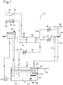
- a fuel cell system 10 includes a fuel cell stack 20 (represented schematically), which uses aqueous potassium hydroxide as electrolyte 12, for example at a concentration of 6 molar.
- the fuel cell stack 20 is supplied with hydrogen gas as fuel, air as oxidant, and electrolyte 12, and operates at an electrolyte temperature of about 65° or 70°C.
- Hydrogen gas is supplied to the fuel cell stack 20 from a hydrogen storage cylinder 22 through a regulator 24 and a control valve 26, and an exhaust gas stream emerges through a first gas outlet duct 28.
- Air is supplied by a blower 30, and is cleaned by passing through a scrubber 32 and a filter 34 before it reaches the fuel cell stack 20, and spent air emerges through a second gas outlet duct 38.
- the fuel cell stack 20 is represented schematically, as its detailed structure is not the subject of the present invention, but in this example it consists of a stack of fuel cells, each fuel cell comprising a liquid electrolyte chamber between opposed electrodes, the electrodes being an anode and a cathode.
- air flows through a gas chamber adjacent to the cathode, to emerge as the spent air.
- hydrogen flows through a gas chamber adjacent to the anode, and the exhaust gas stream emerges, which may be referred to as a purge stream.
- Operation of the fuel cell stack 20 generates electricity, and also generates water by virtue of the chemical reactions described above. In addition water evaporates, and both the exhaust gas stream and the spent air contain water vapour. The overall result would be a steady loss of water from the electrolyte 12.
- the electrolyte 12 is stored in an electrolyte storage tank 40 provided with a vent 41.
- a pump 42 circulates electrolyte from the storage tank 40 into a header tank 44 provided with a vent 45, the header tank 44 having an overflow pipe 46 so that electrolyte returns to the storage tank 40. This ensures that the level of electrolyte in the header tank 44 is constant.
- the electrolyte is supplied at constant pressure through a duct 47 to the fuel cell stack 20; and spent electrolyte returns to the storage tank 40 through a return duct 48 including a heat exchanger 49 to remove excess heat.
- the first gas outlet duct 28 includes a heat exchanger 50 and a gas/liquid separator 51 which condenses water vapour from the emerging exhaust gas stream, so that the cooled exhaust gas stream emerges through an outlet 52, while a stream of water emerges from an outlet 53.
- the second gas outlet duct 38 includes a heat exchanger 50 and a gas/liquid separator 51 to condense water vapour from the spent air, so that the cooled spent air emerges through an outlet 54 and a stream of water emerges from an outlet 55.
- the streams of water from the outlet 53 and the outlet 55 are fed through a common feed pipe 56 into a water storage tank 60 immediately adjacent to the electrolyte storage tank 40.
- the water storage tank 60 includes a number of horizontal baffles 62 extending from opposite walls, which suppress turbulence due to the in-flowing water, and is provided with an overflow 64 communicating with a waste water pipe 65.
- the water storage tank 60 contains water 66 up to a level set by the height of the overflow 64.
- the water storage tank 60 shares a common wall with the electrolyte storage tank 40, so the water 66 is warmed by the electrolyte 12, as heat passes through that common wall.
- a short linking duct 68 which provides fluid communication between the water storage tank 60 and the electrolyte storage tank 40, and the linking duct 68 includes a non-return valve 70.
- the height of the overflow 64 is selected such that if the level of electrolyte 12 in the electrolyte storage tank 40 is at its desired level, then at the position of the linking duct 68 the hydrostatic pressure due to the electrolyte 12 is the same as the hydrostatic pressure due to the water 66. It will be appreciated that the liquid levels are not the same, because the densities of the electrolyte 12 and the water 66 are different.
- the diameter of the linking duct 68 may for example be 3 or 4 mm, but in any event the diameter should be such that that water flows continuously through the linking duct 68 at a sufficient flow velocity to prevent any back-diffusion of potassium hydroxide.
- electrolyte 12 is introduced into the electrolyte storage tank 40, and the non-return valve 70 prevents the electrolyte 12 flowing into the water storage tank 60.
- the non-return valve 70 does not have an impact on the water flow, and there is no tendency for the electrolyte 12 to flow in the reverse direction.
- the linking duct 68 which is shown as being a straight duct through the common wall, might instead be a U-shaped duct linking the bottom portions of the storage tanks 40 and 60 and projecting below the bottoms of the storage tanks 40 and 60.
- the non-return valve 70 in another alternative, may be replaced by a manual valve, which would be closed during initial setup, when electrolyte 12 is being introduced, and would be opened once there was the appropriate level of water in the water storage tank 60, and the cell stack 20 had reached a steady state of operation.
- the overflow 64 may be replaced by a sill or weir over which excess water passes; and such a sill or weir may be of adjustable height.
- the spent air stream and the exhaust gas stream are combined, and are passed through a single heat exchanger 50 followed by a liquid/gas separator 51, to generate the stream of water for the feed pipe 56.
Landscapes
- Life Sciences & Earth Sciences (AREA)
- Engineering & Computer Science (AREA)
- Manufacturing & Machinery (AREA)
- Sustainable Development (AREA)
- Sustainable Energy (AREA)
- Chemical & Material Sciences (AREA)
- Chemical Kinetics & Catalysis (AREA)
- Electrochemistry (AREA)
- General Chemical & Material Sciences (AREA)
- Fuel Cell (AREA)
Claims (7)
- Flüssigelektrolyt-Brennstoffzellensystem (10), das mindestens eine Brennstoffzelle (20), wobei jede Brennstoffzelle eine Flüssigelektrolytkammer zwischen entgegengesetzten Elektroden umfasst, wobei die Elektroden eine Anode und eine Kathode sind, und Mittel (22, 30) zum Liefern einer Gasströmung zu einer Gaskammer, die einer Elektrode benachbart ist, und Abziehen (28, 38) einer Abgasströmung von der der Elektrode benachbarten Gaskammer umfasst, wobei das System auch einen Flüssigelektrolyt-Vorratsbehälter (40) und Mittel (42) zum Inumlaufbringen von Flüssigelektrolyt zwischen dem Flüssigelektrolyt-Vorratsbehälter (40) und jeder Flüssigelektrolytkammer umfasst, wobei das System einen Wasservorratsbehälter (60) und Mittel (50, 51, 53, 55) zum Kondensieren von Wasserdampf von der Abgasströmung und zum Zuführen (56) des kondensierten Wasserdampfs in den Wasservorratsbehälter (60) umfasst; der Wasservorratsbehälter (60) einen Überlaufauslass (64) aufweist; und mit einem Kanal (68), der eine Verbindung zwischen dem Flüssigelektrolyt- Vorratsbehälter (40) und dem Wasservorratsbehälter (60) unter der Höhe des Überlaufauslasses (64) bereitstellt; dadurch gekennzeichnet, dass der Verbindungskanal (68) ein Rückschlagventil (70) oder ein Handschaltventil umfasst; wobei der Elektrolytumlaufweg einen Falltank (44) mit einem Überlauf (46) umfasst; und der Wasservorratsbehälter (60) dem Flüssigelektrolyt-Vorratsbehälter (40) benachbart ist und mit dem Elektrolytvorratsbehälter (40) eine gemeinsame Wand teilt, derart, dass beim Gebrauch Wasser in dem Wasservorratsbehälter (60) durch den Elektrolyt (12) in dem Elektrolytvorratsbehälter (40) erwärmt wird, während Wärme die gemeinsame Wand durchquert.
- Flüssigelektrolyt-Brennstoffzellensystem nach Anspruch 1, wobei die Höhe des Überlaufauslasses (64) verstellbar ist.
- Flüssigelektrolyt-Brennstoffzellensystem nach Anspruch 1 oder Anspruch 2, wobei die Höhe des Überlaufauslasses (64) derart eingestellt ist, dass, wenn der Elektrolyt in dem Elektrolytvorratsbehälter (60) sich auf einem gewünschten Pegel befindet, der Druck an der Höhe des Verbindungskanals (68) sowohl im Elektrolytvorratsbehälter (40) als auch im Wasservorratsbehälter (60) gleich ist.
- Flüssigelektrolyt-Brennstoffzellensystem nach einem der vorhergehenden Ansprüche, wobei die Querschnittsfläche des Verbindungskanals (68) derart ist, dass während des Betriebs die Strömungsgeschwindigkeit von Wasser durch den Verbindungskanal (68) eine Rückdiffusion von Elektrolyt verhindert.
- Flüssigelektrolyt-Brennstoffzellensystem nach einem der vorhergehenden Ansprüche, wobei der Wasservorratsbehälter (60) mehrere Stromstörer (62) umfasst, um Turbulenz zu unterdrücken.
- Flüssigelektrolyt-Brennstoffzellensystem nach einem der vorhergehenden Ansprüche, wobei die Abgasströmung (38) von einer Gaskammer abgezogen wird, die einer Kathode benachbart ist.
- Flüssigelektrolyt-Brennstoffzellensystem nach einem der vorhergehenden Ansprüche, wobei entsprechende Gasströmungen Gaskammern bereitgestellt werden, die der Anode und der Kathode benachbart sind, und Abgasströmungen (28, 38) von den Gaskammern hervortreten, die der Anode und der Kathode benachbart sind, und Mittel (50, 51) zum Kondensieren von Wasserdampf und zum Zuführen des kondensierten Wasserdampfs in den Wasservorratsbehälter (60) für jede von den Abgasströmungen (28, 38) bereitgestellt sind.
Applications Claiming Priority (2)
| Application Number | Priority Date | Filing Date | Title |
|---|---|---|---|
| GB201200260A GB201200260D0 (en) | 2012-01-09 | 2012-01-09 | Fuel cell system |
| PCT/GB2012/053070 WO2013104879A1 (en) | 2012-01-09 | 2012-12-10 | A liquid electrolyte fuel cell system |
Publications (2)
| Publication Number | Publication Date |
|---|---|
| EP2803102A1 EP2803102A1 (de) | 2014-11-19 |
| EP2803102B1 true EP2803102B1 (de) | 2017-08-02 |
Family
ID=45788632
Family Applications (1)
| Application Number | Title | Priority Date | Filing Date |
|---|---|---|---|
| EP12799266.7A Not-in-force EP2803102B1 (de) | 2012-01-09 | 2012-12-10 | Festelektrolyt-brennstoffzellensystem |
Country Status (11)
| Country | Link |
|---|---|
| US (1) | US9564651B2 (de) |
| EP (1) | EP2803102B1 (de) |
| JP (1) | JP6164751B2 (de) |
| KR (1) | KR101980067B1 (de) |
| AU (1) | AU2012365474B2 (de) |
| CA (1) | CA2862826A1 (de) |
| EA (1) | EA201491343A1 (de) |
| GB (1) | GB201200260D0 (de) |
| TW (1) | TW201347287A (de) |
| WO (1) | WO2013104879A1 (de) |
| ZA (1) | ZA201404300B (de) |
Families Citing this family (1)
| Publication number | Priority date | Publication date | Assignee | Title |
|---|---|---|---|---|
| JP2025511796A (ja) * | 2022-04-07 | 2025-04-16 | ハイサタ・ピーティーワイ・リミテッド | 液体関連の機構を有する電気合成電池又は電気エネルギー電池 |
Family Cites Families (16)
| Publication number | Priority date | Publication date | Assignee | Title |
|---|---|---|---|---|
| US3287167A (en) * | 1961-10-18 | 1966-11-22 | Exxon Research Engineering Co | Method and apparatus for controlling operations of fuel cells |
| US3244564A (en) * | 1961-12-04 | 1966-04-05 | Phillips Petroleum Co | Fuel cell |
| AT277342B (de) | 1967-03-21 | 1969-12-29 | Siemens Ag | Verfahren und Vorrichtung zur gemeinsamen Abführung von Verlustwärme und Reaktionswasser aus Brennstoffelementen |
| JPS4825578B1 (de) * | 1968-02-22 | 1973-07-30 | ||
| JPS49121937A (de) * | 1973-03-30 | 1974-11-21 | ||
| JPS61225774A (ja) | 1985-03-29 | 1986-10-07 | Shin Kobe Electric Mach Co Ltd | 酸性電解液型液体燃料電池 |
| JPS6391162U (de) * | 1986-12-03 | 1988-06-13 | ||
| JPH01235163A (ja) * | 1988-03-14 | 1989-09-20 | Fuji Electric Co Ltd | アルカリ型燃料電池 |
| US6869710B2 (en) | 2001-02-09 | 2005-03-22 | Evionyx, Inc. | Metal air cell system |
| US20050142403A1 (en) | 2003-12-30 | 2005-06-30 | Kurt Ulmer | Fuel cell system |
| US20090325012A1 (en) * | 2004-12-17 | 2009-12-31 | Astris Energi Inc. | Alkaline fuel cell system |
| JP5040200B2 (ja) * | 2006-07-18 | 2012-10-03 | 富士電機株式会社 | 燃料電池発電装置 |
| WO2010096028A1 (en) * | 2009-02-17 | 2010-08-26 | Utc Power Corporation | Water treatment system and method for a fuel cell power plant |
| JP2010244924A (ja) * | 2009-04-08 | 2010-10-28 | Panasonic Corp | 燃料電池システム |
| TWI370575B (en) | 2009-05-12 | 2012-08-11 | Young Green Energy Co | Heat exchanging apparatus |
| GB201001972D0 (en) * | 2010-02-08 | 2010-03-24 | Afc Energy Plc | Cell stack system |
-
2012
- 2012-01-09 GB GB201200260A patent/GB201200260D0/en not_active Ceased
- 2012-12-10 WO PCT/GB2012/053070 patent/WO2013104879A1/en not_active Ceased
- 2012-12-10 JP JP2014550754A patent/JP6164751B2/ja not_active Expired - Fee Related
- 2012-12-10 EA EA201491343A patent/EA201491343A1/ru unknown
- 2012-12-10 AU AU2012365474A patent/AU2012365474B2/en not_active Ceased
- 2012-12-10 CA CA2862826A patent/CA2862826A1/en not_active Abandoned
- 2012-12-10 EP EP12799266.7A patent/EP2803102B1/de not_active Not-in-force
- 2012-12-10 US US14/370,731 patent/US9564651B2/en not_active Expired - Fee Related
- 2012-12-10 KR KR1020147022103A patent/KR101980067B1/ko not_active Expired - Fee Related
-
2013
- 2013-01-07 TW TW102100400A patent/TW201347287A/zh unknown
-
2014
- 2014-06-11 ZA ZA2014/04300A patent/ZA201404300B/en unknown
Also Published As
| Publication number | Publication date |
|---|---|
| KR101980067B1 (ko) | 2019-05-21 |
| JP6164751B2 (ja) | 2017-07-19 |
| JP2015503835A (ja) | 2015-02-02 |
| ZA201404300B (en) | 2015-09-30 |
| US20150004505A1 (en) | 2015-01-01 |
| EP2803102A1 (de) | 2014-11-19 |
| AU2012365474A1 (en) | 2014-07-31 |
| GB201200260D0 (en) | 2012-02-22 |
| KR20140117504A (ko) | 2014-10-07 |
| TW201347287A (zh) | 2013-11-16 |
| AU2012365474B2 (en) | 2017-03-16 |
| CA2862826A1 (en) | 2013-07-18 |
| US9564651B2 (en) | 2017-02-07 |
| EA201491343A1 (ru) | 2014-11-28 |
| WO2013104879A1 (en) | 2013-07-18 |
Similar Documents
| Publication | Publication Date | Title |
|---|---|---|
| AU2014214641B2 (en) | Water recapture/recycle system in electrochemical cells | |
| US7517608B2 (en) | Inherently safe redox flow battery storage system | |
| US9099722B2 (en) | Recombinator for flowing electrolyte battery | |
| JP6100065B2 (ja) | 燃料電池システム用イオン交換装置 | |
| JP2012204300A (ja) | 金属空気電池システム | |
| JP2005235586A (ja) | 燃料電池システム | |
| EP2803102B1 (de) | Festelektrolyt-brennstoffzellensystem | |
| JP2007242491A (ja) | 燃料電池システムおよびその運転制御方法 | |
| AU2013257833B2 (en) | Fuel cell system | |
| CN101300705B (zh) | 用于直接甲醇燃料电池的具有稳定结构的水控制器系统 | |
| JP5428461B2 (ja) | 燃料電池システム | |
| JP2005032600A (ja) | 気液分離システムおよび気液分離方法 | |
| JP5308044B2 (ja) | 気液分離器 | |
| US20070148505A1 (en) | Humidifying a reactant flow of a fuel cell system | |
| WO2014111686A1 (en) | Fuel cell system | |
| JP2017135056A (ja) | 再生型燃料電池装置及び該再生型燃料電池装置の運転方法 | |
| US20090081507A1 (en) | Fuel cell system | |
| JP2006286556A (ja) | 燃料電池システム | |
| JP2015065090A (ja) | 燃料電池システム |
Legal Events
| Date | Code | Title | Description |
|---|---|---|---|
| PUAI | Public reference made under article 153(3) epc to a published international application that has entered the european phase |
Free format text: ORIGINAL CODE: 0009012 |
|
| 17P | Request for examination filed |
Effective date: 20140624 |
|
| AK | Designated contracting states |
Kind code of ref document: A1 Designated state(s): AL AT BE BG CH CY CZ DE DK EE ES FI FR GB GR HR HU IE IS IT LI LT LU LV MC MK MT NL NO PL PT RO RS SE SI SK SM TR |
|
| DAX | Request for extension of the european patent (deleted) | ||
| 17Q | First examination report despatched |
Effective date: 20150807 |
|
| GRAP | Despatch of communication of intention to grant a patent |
Free format text: ORIGINAL CODE: EPIDOSNIGR1 |
|
| INTG | Intention to grant announced |
Effective date: 20170228 |
|
| GRAS | Grant fee paid |
Free format text: ORIGINAL CODE: EPIDOSNIGR3 |
|
| GRAA | (expected) grant |
Free format text: ORIGINAL CODE: 0009210 |
|
| AK | Designated contracting states |
Kind code of ref document: B1 Designated state(s): AL AT BE BG CH CY CZ DE DK EE ES FI FR GB GR HR HU IE IS IT LI LT LU LV MC MK MT NL NO PL PT RO RS SE SI SK SM TR |
|
| REG | Reference to a national code |
Ref country code: CH Ref legal event code: EP Ref country code: AT Ref legal event code: REF Ref document number: 915390 Country of ref document: AT Kind code of ref document: T Effective date: 20170815 |
|
| REG | Reference to a national code |
Ref country code: IE Ref legal event code: FG4D |
|
| REG | Reference to a national code |
Ref country code: DE Ref legal event code: R096 Ref document number: 602012035411 Country of ref document: DE |
|
| REG | Reference to a national code |
Ref country code: NL Ref legal event code: MP Effective date: 20170802 |
|
| REG | Reference to a national code |
Ref country code: AT Ref legal event code: MK05 Ref document number: 915390 Country of ref document: AT Kind code of ref document: T Effective date: 20170802 |
|
| REG | Reference to a national code |
Ref country code: LT Ref legal event code: MG4D |
|
| PG25 | Lapsed in a contracting state [announced via postgrant information from national office to epo] |
Ref country code: LT Free format text: LAPSE BECAUSE OF FAILURE TO SUBMIT A TRANSLATION OF THE DESCRIPTION OR TO PAY THE FEE WITHIN THE PRESCRIBED TIME-LIMIT Effective date: 20170802 Ref country code: SE Free format text: LAPSE BECAUSE OF FAILURE TO SUBMIT A TRANSLATION OF THE DESCRIPTION OR TO PAY THE FEE WITHIN THE PRESCRIBED TIME-LIMIT Effective date: 20170802 Ref country code: NL Free format text: LAPSE BECAUSE OF FAILURE TO SUBMIT A TRANSLATION OF THE DESCRIPTION OR TO PAY THE FEE WITHIN THE PRESCRIBED TIME-LIMIT Effective date: 20170802 Ref country code: HR Free format text: LAPSE BECAUSE OF FAILURE TO SUBMIT A TRANSLATION OF THE DESCRIPTION OR TO PAY THE FEE WITHIN THE PRESCRIBED TIME-LIMIT Effective date: 20170802 Ref country code: AT Free format text: LAPSE BECAUSE OF FAILURE TO SUBMIT A TRANSLATION OF THE DESCRIPTION OR TO PAY THE FEE WITHIN THE PRESCRIBED TIME-LIMIT Effective date: 20170802 Ref country code: NO Free format text: LAPSE BECAUSE OF FAILURE TO SUBMIT A TRANSLATION OF THE DESCRIPTION OR TO PAY THE FEE WITHIN THE PRESCRIBED TIME-LIMIT Effective date: 20171102 Ref country code: FI Free format text: LAPSE BECAUSE OF FAILURE TO SUBMIT A TRANSLATION OF THE DESCRIPTION OR TO PAY THE FEE WITHIN THE PRESCRIBED TIME-LIMIT Effective date: 20170802 |
|
| PG25 | Lapsed in a contracting state [announced via postgrant information from national office to epo] |
Ref country code: PL Free format text: LAPSE BECAUSE OF FAILURE TO SUBMIT A TRANSLATION OF THE DESCRIPTION OR TO PAY THE FEE WITHIN THE PRESCRIBED TIME-LIMIT Effective date: 20170802 Ref country code: LV Free format text: LAPSE BECAUSE OF FAILURE TO SUBMIT A TRANSLATION OF THE DESCRIPTION OR TO PAY THE FEE WITHIN THE PRESCRIBED TIME-LIMIT Effective date: 20170802 Ref country code: BG Free format text: LAPSE BECAUSE OF FAILURE TO SUBMIT A TRANSLATION OF THE DESCRIPTION OR TO PAY THE FEE WITHIN THE PRESCRIBED TIME-LIMIT Effective date: 20171102 Ref country code: RS Free format text: LAPSE BECAUSE OF FAILURE TO SUBMIT A TRANSLATION OF THE DESCRIPTION OR TO PAY THE FEE WITHIN THE PRESCRIBED TIME-LIMIT Effective date: 20170802 Ref country code: ES Free format text: LAPSE BECAUSE OF FAILURE TO SUBMIT A TRANSLATION OF THE DESCRIPTION OR TO PAY THE FEE WITHIN THE PRESCRIBED TIME-LIMIT Effective date: 20170802 Ref country code: IS Free format text: LAPSE BECAUSE OF FAILURE TO SUBMIT A TRANSLATION OF THE DESCRIPTION OR TO PAY THE FEE WITHIN THE PRESCRIBED TIME-LIMIT Effective date: 20171202 Ref country code: GR Free format text: LAPSE BECAUSE OF FAILURE TO SUBMIT A TRANSLATION OF THE DESCRIPTION OR TO PAY THE FEE WITHIN THE PRESCRIBED TIME-LIMIT Effective date: 20171103 |
|
| PG25 | Lapsed in a contracting state [announced via postgrant information from national office to epo] |
Ref country code: DK Free format text: LAPSE BECAUSE OF FAILURE TO SUBMIT A TRANSLATION OF THE DESCRIPTION OR TO PAY THE FEE WITHIN THE PRESCRIBED TIME-LIMIT Effective date: 20170802 Ref country code: RO Free format text: LAPSE BECAUSE OF FAILURE TO SUBMIT A TRANSLATION OF THE DESCRIPTION OR TO PAY THE FEE WITHIN THE PRESCRIBED TIME-LIMIT Effective date: 20170802 Ref country code: CZ Free format text: LAPSE BECAUSE OF FAILURE TO SUBMIT A TRANSLATION OF THE DESCRIPTION OR TO PAY THE FEE WITHIN THE PRESCRIBED TIME-LIMIT Effective date: 20170802 |
|
| REG | Reference to a national code |
Ref country code: DE Ref legal event code: R097 Ref document number: 602012035411 Country of ref document: DE |
|
| PG25 | Lapsed in a contracting state [announced via postgrant information from national office to epo] |
Ref country code: SM Free format text: LAPSE BECAUSE OF FAILURE TO SUBMIT A TRANSLATION OF THE DESCRIPTION OR TO PAY THE FEE WITHIN THE PRESCRIBED TIME-LIMIT Effective date: 20170802 Ref country code: EE Free format text: LAPSE BECAUSE OF FAILURE TO SUBMIT A TRANSLATION OF THE DESCRIPTION OR TO PAY THE FEE WITHIN THE PRESCRIBED TIME-LIMIT Effective date: 20170802 Ref country code: IT Free format text: LAPSE BECAUSE OF FAILURE TO SUBMIT A TRANSLATION OF THE DESCRIPTION OR TO PAY THE FEE WITHIN THE PRESCRIBED TIME-LIMIT Effective date: 20170802 Ref country code: SK Free format text: LAPSE BECAUSE OF FAILURE TO SUBMIT A TRANSLATION OF THE DESCRIPTION OR TO PAY THE FEE WITHIN THE PRESCRIBED TIME-LIMIT Effective date: 20170802 |
|
| PLBE | No opposition filed within time limit |
Free format text: ORIGINAL CODE: 0009261 |
|
| STAA | Information on the status of an ep patent application or granted ep patent |
Free format text: STATUS: NO OPPOSITION FILED WITHIN TIME LIMIT |
|
| 26N | No opposition filed |
Effective date: 20180503 |
|
| REG | Reference to a national code |
Ref country code: CH Ref legal event code: PL |
|
| PG25 | Lapsed in a contracting state [announced via postgrant information from national office to epo] |
Ref country code: SI Free format text: LAPSE BECAUSE OF FAILURE TO SUBMIT A TRANSLATION OF THE DESCRIPTION OR TO PAY THE FEE WITHIN THE PRESCRIBED TIME-LIMIT Effective date: 20170802 |
|
| REG | Reference to a national code |
Ref country code: IE Ref legal event code: MM4A |
|
| PG25 | Lapsed in a contracting state [announced via postgrant information from national office to epo] |
Ref country code: MT Free format text: LAPSE BECAUSE OF NON-PAYMENT OF DUE FEES Effective date: 20171210 Ref country code: LU Free format text: LAPSE BECAUSE OF NON-PAYMENT OF DUE FEES Effective date: 20171210 |
|
| REG | Reference to a national code |
Ref country code: FR Ref legal event code: ST Effective date: 20180831 |
|
| REG | Reference to a national code |
Ref country code: BE Ref legal event code: MM Effective date: 20171231 |
|
| PG25 | Lapsed in a contracting state [announced via postgrant information from national office to epo] |
Ref country code: FR Free format text: LAPSE BECAUSE OF NON-PAYMENT OF DUE FEES Effective date: 20180102 Ref country code: IE Free format text: LAPSE BECAUSE OF NON-PAYMENT OF DUE FEES Effective date: 20171210 |
|
| PG25 | Lapsed in a contracting state [announced via postgrant information from national office to epo] |
Ref country code: CH Free format text: LAPSE BECAUSE OF NON-PAYMENT OF DUE FEES Effective date: 20171231 Ref country code: BE Free format text: LAPSE BECAUSE OF NON-PAYMENT OF DUE FEES Effective date: 20171231 Ref country code: LI Free format text: LAPSE BECAUSE OF NON-PAYMENT OF DUE FEES Effective date: 20171231 |
|
| PG25 | Lapsed in a contracting state [announced via postgrant information from national office to epo] |
Ref country code: MC Free format text: LAPSE BECAUSE OF FAILURE TO SUBMIT A TRANSLATION OF THE DESCRIPTION OR TO PAY THE FEE WITHIN THE PRESCRIBED TIME-LIMIT Effective date: 20170802 Ref country code: HU Free format text: LAPSE BECAUSE OF FAILURE TO SUBMIT A TRANSLATION OF THE DESCRIPTION OR TO PAY THE FEE WITHIN THE PRESCRIBED TIME-LIMIT; INVALID AB INITIO Effective date: 20121210 |
|
| PG25 | Lapsed in a contracting state [announced via postgrant information from national office to epo] |
Ref country code: CY Free format text: LAPSE BECAUSE OF FAILURE TO SUBMIT A TRANSLATION OF THE DESCRIPTION OR TO PAY THE FEE WITHIN THE PRESCRIBED TIME-LIMIT Effective date: 20170802 |
|
| PG25 | Lapsed in a contracting state [announced via postgrant information from national office to epo] |
Ref country code: MK Free format text: LAPSE BECAUSE OF FAILURE TO SUBMIT A TRANSLATION OF THE DESCRIPTION OR TO PAY THE FEE WITHIN THE PRESCRIBED TIME-LIMIT Effective date: 20170802 |
|
| PGFP | Annual fee paid to national office [announced via postgrant information from national office to epo] |
Ref country code: DE Payment date: 20191206 Year of fee payment: 8 |
|
| PG25 | Lapsed in a contracting state [announced via postgrant information from national office to epo] |
Ref country code: TR Free format text: LAPSE BECAUSE OF FAILURE TO SUBMIT A TRANSLATION OF THE DESCRIPTION OR TO PAY THE FEE WITHIN THE PRESCRIBED TIME-LIMIT Effective date: 20170802 |
|
| PGFP | Annual fee paid to national office [announced via postgrant information from national office to epo] |
Ref country code: GB Payment date: 20191205 Year of fee payment: 8 |
|
| PG25 | Lapsed in a contracting state [announced via postgrant information from national office to epo] |
Ref country code: PT Free format text: LAPSE BECAUSE OF FAILURE TO SUBMIT A TRANSLATION OF THE DESCRIPTION OR TO PAY THE FEE WITHIN THE PRESCRIBED TIME-LIMIT Effective date: 20170802 |
|
| PG25 | Lapsed in a contracting state [announced via postgrant information from national office to epo] |
Ref country code: AL Free format text: LAPSE BECAUSE OF FAILURE TO SUBMIT A TRANSLATION OF THE DESCRIPTION OR TO PAY THE FEE WITHIN THE PRESCRIBED TIME-LIMIT Effective date: 20170802 |
|
| REG | Reference to a national code |
Ref country code: DE Ref legal event code: R119 Ref document number: 602012035411 Country of ref document: DE |
|
| GBPC | Gb: european patent ceased through non-payment of renewal fee |
Effective date: 20201210 |
|
| PG25 | Lapsed in a contracting state [announced via postgrant information from national office to epo] |
Ref country code: DE Free format text: LAPSE BECAUSE OF NON-PAYMENT OF DUE FEES Effective date: 20210701 Ref country code: GB Free format text: LAPSE BECAUSE OF NON-PAYMENT OF DUE FEES Effective date: 20201210 |