EP2802058A1 - Electric automobile and integrated control system thereof - Google Patents
Electric automobile and integrated control system thereof Download PDFInfo
- Publication number
- EP2802058A1 EP2802058A1 EP12861486.4A EP12861486A EP2802058A1 EP 2802058 A1 EP2802058 A1 EP 2802058A1 EP 12861486 A EP12861486 A EP 12861486A EP 2802058 A1 EP2802058 A1 EP 2802058A1
- Authority
- EP
- European Patent Office
- Prior art keywords
- module
- charge
- terminal
- switch
- discharge
- Prior art date
- Legal status (The legal status is an assumption and is not a legal conclusion. Google has not performed a legal analysis and makes no representation as to the accuracy of the status listed.)
- Ceased
Links
Images


Classifications
-
- B—PERFORMING OPERATIONS; TRANSPORTING
- B60—VEHICLES IN GENERAL
- B60L—PROPULSION OF ELECTRICALLY-PROPELLED VEHICLES; SUPPLYING ELECTRIC POWER FOR AUXILIARY EQUIPMENT OF ELECTRICALLY-PROPELLED VEHICLES; ELECTRODYNAMIC BRAKE SYSTEMS FOR VEHICLES IN GENERAL; MAGNETIC SUSPENSION OR LEVITATION FOR VEHICLES; MONITORING OPERATING VARIABLES OF ELECTRICALLY-PROPELLED VEHICLES; ELECTRIC SAFETY DEVICES FOR ELECTRICALLY-PROPELLED VEHICLES
- B60L3/00—Electric devices on electrically-propelled vehicles for safety purposes; Monitoring operating variables, e.g. speed, deceleration or energy consumption
- B60L3/0023—Detecting, eliminating, remedying or compensating for drive train abnormalities, e.g. failures within the drive train
- B60L3/0046—Detecting, eliminating, remedying or compensating for drive train abnormalities, e.g. failures within the drive train relating to electric energy storage systems, e.g. batteries or capacitors
-
- B—PERFORMING OPERATIONS; TRANSPORTING
- B60—VEHICLES IN GENERAL
- B60L—PROPULSION OF ELECTRICALLY-PROPELLED VEHICLES; SUPPLYING ELECTRIC POWER FOR AUXILIARY EQUIPMENT OF ELECTRICALLY-PROPELLED VEHICLES; ELECTRODYNAMIC BRAKE SYSTEMS FOR VEHICLES IN GENERAL; MAGNETIC SUSPENSION OR LEVITATION FOR VEHICLES; MONITORING OPERATING VARIABLES OF ELECTRICALLY-PROPELLED VEHICLES; ELECTRIC SAFETY DEVICES FOR ELECTRICALLY-PROPELLED VEHICLES
- B60L1/00—Supplying electric power to auxiliary equipment of vehicles
- B60L1/003—Supplying electric power to auxiliary equipment of vehicles to auxiliary motors, e.g. for pumps, compressors
-
- B—PERFORMING OPERATIONS; TRANSPORTING
- B60—VEHICLES IN GENERAL
- B60L—PROPULSION OF ELECTRICALLY-PROPELLED VEHICLES; SUPPLYING ELECTRIC POWER FOR AUXILIARY EQUIPMENT OF ELECTRICALLY-PROPELLED VEHICLES; ELECTRODYNAMIC BRAKE SYSTEMS FOR VEHICLES IN GENERAL; MAGNETIC SUSPENSION OR LEVITATION FOR VEHICLES; MONITORING OPERATING VARIABLES OF ELECTRICALLY-PROPELLED VEHICLES; ELECTRIC SAFETY DEVICES FOR ELECTRICALLY-PROPELLED VEHICLES
- B60L1/00—Supplying electric power to auxiliary equipment of vehicles
- B60L1/006—Supplying electric power to auxiliary equipment of vehicles to power outlets
-
- B—PERFORMING OPERATIONS; TRANSPORTING
- B60—VEHICLES IN GENERAL
- B60L—PROPULSION OF ELECTRICALLY-PROPELLED VEHICLES; SUPPLYING ELECTRIC POWER FOR AUXILIARY EQUIPMENT OF ELECTRICALLY-PROPELLED VEHICLES; ELECTRODYNAMIC BRAKE SYSTEMS FOR VEHICLES IN GENERAL; MAGNETIC SUSPENSION OR LEVITATION FOR VEHICLES; MONITORING OPERATING VARIABLES OF ELECTRICALLY-PROPELLED VEHICLES; ELECTRIC SAFETY DEVICES FOR ELECTRICALLY-PROPELLED VEHICLES
- B60L3/00—Electric devices on electrically-propelled vehicles for safety purposes; Monitoring operating variables, e.g. speed, deceleration or energy consumption
- B60L3/0023—Detecting, eliminating, remedying or compensating for drive train abnormalities, e.g. failures within the drive train
- B60L3/003—Detecting, eliminating, remedying or compensating for drive train abnormalities, e.g. failures within the drive train relating to inverters
-
- B—PERFORMING OPERATIONS; TRANSPORTING
- B60—VEHICLES IN GENERAL
- B60L—PROPULSION OF ELECTRICALLY-PROPELLED VEHICLES; SUPPLYING ELECTRIC POWER FOR AUXILIARY EQUIPMENT OF ELECTRICALLY-PROPELLED VEHICLES; ELECTRODYNAMIC BRAKE SYSTEMS FOR VEHICLES IN GENERAL; MAGNETIC SUSPENSION OR LEVITATION FOR VEHICLES; MONITORING OPERATING VARIABLES OF ELECTRICALLY-PROPELLED VEHICLES; ELECTRIC SAFETY DEVICES FOR ELECTRICALLY-PROPELLED VEHICLES
- B60L3/00—Electric devices on electrically-propelled vehicles for safety purposes; Monitoring operating variables, e.g. speed, deceleration or energy consumption
- B60L3/0023—Detecting, eliminating, remedying or compensating for drive train abnormalities, e.g. failures within the drive train
- B60L3/0069—Detecting, eliminating, remedying or compensating for drive train abnormalities, e.g. failures within the drive train relating to the isolation, e.g. ground fault or leak current
-
- B—PERFORMING OPERATIONS; TRANSPORTING
- B60—VEHICLES IN GENERAL
- B60L—PROPULSION OF ELECTRICALLY-PROPELLED VEHICLES; SUPPLYING ELECTRIC POWER FOR AUXILIARY EQUIPMENT OF ELECTRICALLY-PROPELLED VEHICLES; ELECTRODYNAMIC BRAKE SYSTEMS FOR VEHICLES IN GENERAL; MAGNETIC SUSPENSION OR LEVITATION FOR VEHICLES; MONITORING OPERATING VARIABLES OF ELECTRICALLY-PROPELLED VEHICLES; ELECTRIC SAFETY DEVICES FOR ELECTRICALLY-PROPELLED VEHICLES
- B60L50/00—Electric propulsion with power supplied within the vehicle
- B60L50/50—Electric propulsion with power supplied within the vehicle using propulsion power supplied by batteries or fuel cells
- B60L50/51—Electric propulsion with power supplied within the vehicle using propulsion power supplied by batteries or fuel cells characterised by AC-motors
-
- B—PERFORMING OPERATIONS; TRANSPORTING
- B60—VEHICLES IN GENERAL
- B60L—PROPULSION OF ELECTRICALLY-PROPELLED VEHICLES; SUPPLYING ELECTRIC POWER FOR AUXILIARY EQUIPMENT OF ELECTRICALLY-PROPELLED VEHICLES; ELECTRODYNAMIC BRAKE SYSTEMS FOR VEHICLES IN GENERAL; MAGNETIC SUSPENSION OR LEVITATION FOR VEHICLES; MONITORING OPERATING VARIABLES OF ELECTRICALLY-PROPELLED VEHICLES; ELECTRIC SAFETY DEVICES FOR ELECTRICALLY-PROPELLED VEHICLES
- B60L50/00—Electric propulsion with power supplied within the vehicle
- B60L50/50—Electric propulsion with power supplied within the vehicle using propulsion power supplied by batteries or fuel cells
- B60L50/52—Electric propulsion with power supplied within the vehicle using propulsion power supplied by batteries or fuel cells characterised by DC-motors
-
- B—PERFORMING OPERATIONS; TRANSPORTING
- B60—VEHICLES IN GENERAL
- B60L—PROPULSION OF ELECTRICALLY-PROPELLED VEHICLES; SUPPLYING ELECTRIC POWER FOR AUXILIARY EQUIPMENT OF ELECTRICALLY-PROPELLED VEHICLES; ELECTRODYNAMIC BRAKE SYSTEMS FOR VEHICLES IN GENERAL; MAGNETIC SUSPENSION OR LEVITATION FOR VEHICLES; MONITORING OPERATING VARIABLES OF ELECTRICALLY-PROPELLED VEHICLES; ELECTRIC SAFETY DEVICES FOR ELECTRICALLY-PROPELLED VEHICLES
- B60L50/00—Electric propulsion with power supplied within the vehicle
- B60L50/50—Electric propulsion with power supplied within the vehicle using propulsion power supplied by batteries or fuel cells
- B60L50/60—Electric propulsion with power supplied within the vehicle using propulsion power supplied by batteries or fuel cells using power supplied by batteries
-
- B—PERFORMING OPERATIONS; TRANSPORTING
- B60—VEHICLES IN GENERAL
- B60L—PROPULSION OF ELECTRICALLY-PROPELLED VEHICLES; SUPPLYING ELECTRIC POWER FOR AUXILIARY EQUIPMENT OF ELECTRICALLY-PROPELLED VEHICLES; ELECTRODYNAMIC BRAKE SYSTEMS FOR VEHICLES IN GENERAL; MAGNETIC SUSPENSION OR LEVITATION FOR VEHICLES; MONITORING OPERATING VARIABLES OF ELECTRICALLY-PROPELLED VEHICLES; ELECTRIC SAFETY DEVICES FOR ELECTRICALLY-PROPELLED VEHICLES
- B60L53/00—Methods of charging batteries, specially adapted for electric vehicles; Charging stations or on-board charging equipment therefor; Exchange of energy storage elements in electric vehicles
- B60L53/10—Methods of charging batteries, specially adapted for electric vehicles; Charging stations or on-board charging equipment therefor; Exchange of energy storage elements in electric vehicles characterised by the energy transfer between the charging station and the vehicle
- B60L53/11—DC charging controlled by the charging station, e.g. mode 4
-
- B—PERFORMING OPERATIONS; TRANSPORTING
- B60—VEHICLES IN GENERAL
- B60L—PROPULSION OF ELECTRICALLY-PROPELLED VEHICLES; SUPPLYING ELECTRIC POWER FOR AUXILIARY EQUIPMENT OF ELECTRICALLY-PROPELLED VEHICLES; ELECTRODYNAMIC BRAKE SYSTEMS FOR VEHICLES IN GENERAL; MAGNETIC SUSPENSION OR LEVITATION FOR VEHICLES; MONITORING OPERATING VARIABLES OF ELECTRICALLY-PROPELLED VEHICLES; ELECTRIC SAFETY DEVICES FOR ELECTRICALLY-PROPELLED VEHICLES
- B60L53/00—Methods of charging batteries, specially adapted for electric vehicles; Charging stations or on-board charging equipment therefor; Exchange of energy storage elements in electric vehicles
- B60L53/10—Methods of charging batteries, specially adapted for electric vehicles; Charging stations or on-board charging equipment therefor; Exchange of energy storage elements in electric vehicles characterised by the energy transfer between the charging station and the vehicle
- B60L53/14—Conductive energy transfer
- B60L53/16—Connectors, e.g. plugs or sockets, specially adapted for charging electric vehicles
-
- B—PERFORMING OPERATIONS; TRANSPORTING
- B60—VEHICLES IN GENERAL
- B60L—PROPULSION OF ELECTRICALLY-PROPELLED VEHICLES; SUPPLYING ELECTRIC POWER FOR AUXILIARY EQUIPMENT OF ELECTRICALLY-PROPELLED VEHICLES; ELECTRODYNAMIC BRAKE SYSTEMS FOR VEHICLES IN GENERAL; MAGNETIC SUSPENSION OR LEVITATION FOR VEHICLES; MONITORING OPERATING VARIABLES OF ELECTRICALLY-PROPELLED VEHICLES; ELECTRIC SAFETY DEVICES FOR ELECTRICALLY-PROPELLED VEHICLES
- B60L53/00—Methods of charging batteries, specially adapted for electric vehicles; Charging stations or on-board charging equipment therefor; Exchange of energy storage elements in electric vehicles
- B60L53/10—Methods of charging batteries, specially adapted for electric vehicles; Charging stations or on-board charging equipment therefor; Exchange of energy storage elements in electric vehicles characterised by the energy transfer between the charging station and the vehicle
- B60L53/14—Conductive energy transfer
- B60L53/18—Cables specially adapted for charging electric vehicles
-
- B—PERFORMING OPERATIONS; TRANSPORTING
- B60—VEHICLES IN GENERAL
- B60L—PROPULSION OF ELECTRICALLY-PROPELLED VEHICLES; SUPPLYING ELECTRIC POWER FOR AUXILIARY EQUIPMENT OF ELECTRICALLY-PROPELLED VEHICLES; ELECTRODYNAMIC BRAKE SYSTEMS FOR VEHICLES IN GENERAL; MAGNETIC SUSPENSION OR LEVITATION FOR VEHICLES; MONITORING OPERATING VARIABLES OF ELECTRICALLY-PROPELLED VEHICLES; ELECTRIC SAFETY DEVICES FOR ELECTRICALLY-PROPELLED VEHICLES
- B60L53/00—Methods of charging batteries, specially adapted for electric vehicles; Charging stations or on-board charging equipment therefor; Exchange of energy storage elements in electric vehicles
- B60L53/20—Methods of charging batteries, specially adapted for electric vehicles; Charging stations or on-board charging equipment therefor; Exchange of energy storage elements in electric vehicles characterised by converters located in the vehicle
- B60L53/22—Constructional details or arrangements of charging converters specially adapted for charging electric vehicles
-
- B—PERFORMING OPERATIONS; TRANSPORTING
- B60—VEHICLES IN GENERAL
- B60L—PROPULSION OF ELECTRICALLY-PROPELLED VEHICLES; SUPPLYING ELECTRIC POWER FOR AUXILIARY EQUIPMENT OF ELECTRICALLY-PROPELLED VEHICLES; ELECTRODYNAMIC BRAKE SYSTEMS FOR VEHICLES IN GENERAL; MAGNETIC SUSPENSION OR LEVITATION FOR VEHICLES; MONITORING OPERATING VARIABLES OF ELECTRICALLY-PROPELLED VEHICLES; ELECTRIC SAFETY DEVICES FOR ELECTRICALLY-PROPELLED VEHICLES
- B60L53/00—Methods of charging batteries, specially adapted for electric vehicles; Charging stations or on-board charging equipment therefor; Exchange of energy storage elements in electric vehicles
- B60L53/20—Methods of charging batteries, specially adapted for electric vehicles; Charging stations or on-board charging equipment therefor; Exchange of energy storage elements in electric vehicles characterised by converters located in the vehicle
- B60L53/24—Using the vehicle's propulsion converter for charging
-
- B—PERFORMING OPERATIONS; TRANSPORTING
- B60—VEHICLES IN GENERAL
- B60L—PROPULSION OF ELECTRICALLY-PROPELLED VEHICLES; SUPPLYING ELECTRIC POWER FOR AUXILIARY EQUIPMENT OF ELECTRICALLY-PROPELLED VEHICLES; ELECTRODYNAMIC BRAKE SYSTEMS FOR VEHICLES IN GENERAL; MAGNETIC SUSPENSION OR LEVITATION FOR VEHICLES; MONITORING OPERATING VARIABLES OF ELECTRICALLY-PROPELLED VEHICLES; ELECTRIC SAFETY DEVICES FOR ELECTRICALLY-PROPELLED VEHICLES
- B60L53/00—Methods of charging batteries, specially adapted for electric vehicles; Charging stations or on-board charging equipment therefor; Exchange of energy storage elements in electric vehicles
- B60L53/60—Monitoring or controlling charging stations
-
- B—PERFORMING OPERATIONS; TRANSPORTING
- B60—VEHICLES IN GENERAL
- B60L—PROPULSION OF ELECTRICALLY-PROPELLED VEHICLES; SUPPLYING ELECTRIC POWER FOR AUXILIARY EQUIPMENT OF ELECTRICALLY-PROPELLED VEHICLES; ELECTRODYNAMIC BRAKE SYSTEMS FOR VEHICLES IN GENERAL; MAGNETIC SUSPENSION OR LEVITATION FOR VEHICLES; MONITORING OPERATING VARIABLES OF ELECTRICALLY-PROPELLED VEHICLES; ELECTRIC SAFETY DEVICES FOR ELECTRICALLY-PROPELLED VEHICLES
- B60L55/00—Arrangements for supplying energy stored within a vehicle to a power network, i.e. vehicle-to-grid [V2G] arrangements
-
- B—PERFORMING OPERATIONS; TRANSPORTING
- B60—VEHICLES IN GENERAL
- B60L—PROPULSION OF ELECTRICALLY-PROPELLED VEHICLES; SUPPLYING ELECTRIC POWER FOR AUXILIARY EQUIPMENT OF ELECTRICALLY-PROPELLED VEHICLES; ELECTRODYNAMIC BRAKE SYSTEMS FOR VEHICLES IN GENERAL; MAGNETIC SUSPENSION OR LEVITATION FOR VEHICLES; MONITORING OPERATING VARIABLES OF ELECTRICALLY-PROPELLED VEHICLES; ELECTRIC SAFETY DEVICES FOR ELECTRICALLY-PROPELLED VEHICLES
- B60L58/00—Methods or circuit arrangements for monitoring or controlling batteries or fuel cells, specially adapted for electric vehicles
- B60L58/10—Methods or circuit arrangements for monitoring or controlling batteries or fuel cells, specially adapted for electric vehicles for monitoring or controlling batteries
- B60L58/12—Methods or circuit arrangements for monitoring or controlling batteries or fuel cells, specially adapted for electric vehicles for monitoring or controlling batteries responding to state of charge [SoC]
-
- B—PERFORMING OPERATIONS; TRANSPORTING
- B60—VEHICLES IN GENERAL
- B60L—PROPULSION OF ELECTRICALLY-PROPELLED VEHICLES; SUPPLYING ELECTRIC POWER FOR AUXILIARY EQUIPMENT OF ELECTRICALLY-PROPELLED VEHICLES; ELECTRODYNAMIC BRAKE SYSTEMS FOR VEHICLES IN GENERAL; MAGNETIC SUSPENSION OR LEVITATION FOR VEHICLES; MONITORING OPERATING VARIABLES OF ELECTRICALLY-PROPELLED VEHICLES; ELECTRIC SAFETY DEVICES FOR ELECTRICALLY-PROPELLED VEHICLES
- B60L58/00—Methods or circuit arrangements for monitoring or controlling batteries or fuel cells, specially adapted for electric vehicles
- B60L58/10—Methods or circuit arrangements for monitoring or controlling batteries or fuel cells, specially adapted for electric vehicles for monitoring or controlling batteries
- B60L58/24—Methods or circuit arrangements for monitoring or controlling batteries or fuel cells, specially adapted for electric vehicles for monitoring or controlling batteries for controlling the temperature of batteries
- B60L58/25—Methods or circuit arrangements for monitoring or controlling batteries or fuel cells, specially adapted for electric vehicles for monitoring or controlling batteries for controlling the temperature of batteries by controlling the electric load
-
- H—ELECTRICITY
- H02—GENERATION; CONVERSION OR DISTRIBUTION OF ELECTRIC POWER
- H02J—CIRCUIT ARRANGEMENTS OR SYSTEMS FOR SUPPLYING OR DISTRIBUTING ELECTRIC POWER; SYSTEMS FOR STORING ELECTRIC ENERGY
- H02J3/00—Circuit arrangements for ac mains or ac distribution networks
- H02J3/28—Arrangements for balancing of the load in a network by storage of energy
- H02J3/32—Arrangements for balancing of the load in a network by storage of energy using batteries with converting means
- H02J3/322—Arrangements for balancing of the load in a network by storage of energy using batteries with converting means the battery being on-board an electric or hybrid vehicle, e.g. vehicle to grid arrangements [V2G], power aggregation, use of the battery for network load balancing, coordinated or cooperative battery charging
-
- H—ELECTRICITY
- H02—GENERATION; CONVERSION OR DISTRIBUTION OF ELECTRIC POWER
- H02J—CIRCUIT ARRANGEMENTS OR SYSTEMS FOR SUPPLYING OR DISTRIBUTING ELECTRIC POWER; SYSTEMS FOR STORING ELECTRIC ENERGY
- H02J5/00—Circuit arrangements for transfer of electric power between ac networks and dc networks
-
- H—ELECTRICITY
- H02—GENERATION; CONVERSION OR DISTRIBUTION OF ELECTRIC POWER
- H02J—CIRCUIT ARRANGEMENTS OR SYSTEMS FOR SUPPLYING OR DISTRIBUTING ELECTRIC POWER; SYSTEMS FOR STORING ELECTRIC ENERGY
- H02J7/00—Circuit arrangements for charging or depolarising batteries or for supplying loads from batteries
- H02J7/0029—Circuit arrangements for charging or depolarising batteries or for supplying loads from batteries with safety or protection devices or circuits
- H02J7/0036—Circuit arrangements for charging or depolarising batteries or for supplying loads from batteries with safety or protection devices or circuits using connection detecting circuits
-
- H—ELECTRICITY
- H02—GENERATION; CONVERSION OR DISTRIBUTION OF ELECTRIC POWER
- H02J—CIRCUIT ARRANGEMENTS OR SYSTEMS FOR SUPPLYING OR DISTRIBUTING ELECTRIC POWER; SYSTEMS FOR STORING ELECTRIC ENERGY
- H02J7/00—Circuit arrangements for charging or depolarising batteries or for supplying loads from batteries
- H02J7/0063—Circuit arrangements for charging or depolarising batteries or for supplying loads from batteries with circuits adapted for supplying loads from the battery
-
- H—ELECTRICITY
- H02—GENERATION; CONVERSION OR DISTRIBUTION OF ELECTRIC POWER
- H02J—CIRCUIT ARRANGEMENTS OR SYSTEMS FOR SUPPLYING OR DISTRIBUTING ELECTRIC POWER; SYSTEMS FOR STORING ELECTRIC ENERGY
- H02J7/00—Circuit arrangements for charging or depolarising batteries or for supplying loads from batteries
- H02J7/0068—Battery or charger load switching, e.g. concurrent charging and load supply
-
- H—ELECTRICITY
- H02—GENERATION; CONVERSION OR DISTRIBUTION OF ELECTRIC POWER
- H02J—CIRCUIT ARRANGEMENTS OR SYSTEMS FOR SUPPLYING OR DISTRIBUTING ELECTRIC POWER; SYSTEMS FOR STORING ELECTRIC ENERGY
- H02J7/00—Circuit arrangements for charging or depolarising batteries or for supplying loads from batteries
- H02J7/007—Regulation of charging or discharging current or voltage
- H02J7/00712—Regulation of charging or discharging current or voltage the cycle being controlled or terminated in response to electric parameters
- H02J7/007182—Regulation of charging or discharging current or voltage the cycle being controlled or terminated in response to electric parameters in response to battery voltage
-
- H—ELECTRICITY
- H02—GENERATION; CONVERSION OR DISTRIBUTION OF ELECTRIC POWER
- H02J—CIRCUIT ARRANGEMENTS OR SYSTEMS FOR SUPPLYING OR DISTRIBUTING ELECTRIC POWER; SYSTEMS FOR STORING ELECTRIC ENERGY
- H02J7/00—Circuit arrangements for charging or depolarising batteries or for supplying loads from batteries
- H02J7/34—Parallel operation in networks using both storage and other dc sources, e.g. providing buffering
- H02J7/342—The other DC source being a battery actively interacting with the first one, i.e. battery to battery charging
-
- H—ELECTRICITY
- H02—GENERATION; CONVERSION OR DISTRIBUTION OF ELECTRIC POWER
- H02J—CIRCUIT ARRANGEMENTS OR SYSTEMS FOR SUPPLYING OR DISTRIBUTING ELECTRIC POWER; SYSTEMS FOR STORING ELECTRIC ENERGY
- H02J7/00—Circuit arrangements for charging or depolarising batteries or for supplying loads from batteries
- H02J7/34—Parallel operation in networks using both storage and other dc sources, e.g. providing buffering
- H02J7/345—Parallel operation in networks using both storage and other dc sources, e.g. providing buffering using capacitors as storage or buffering devices
-
- H—ELECTRICITY
- H04—ELECTRIC COMMUNICATION TECHNIQUE
- H04B—TRANSMISSION
- H04B3/00—Line transmission systems
- H04B3/54—Systems for transmission via power distribution lines
- H04B3/542—Systems for transmission via power distribution lines the information being in digital form
-
- B—PERFORMING OPERATIONS; TRANSPORTING
- B60—VEHICLES IN GENERAL
- B60L—PROPULSION OF ELECTRICALLY-PROPELLED VEHICLES; SUPPLYING ELECTRIC POWER FOR AUXILIARY EQUIPMENT OF ELECTRICALLY-PROPELLED VEHICLES; ELECTRODYNAMIC BRAKE SYSTEMS FOR VEHICLES IN GENERAL; MAGNETIC SUSPENSION OR LEVITATION FOR VEHICLES; MONITORING OPERATING VARIABLES OF ELECTRICALLY-PROPELLED VEHICLES; ELECTRIC SAFETY DEVICES FOR ELECTRICALLY-PROPELLED VEHICLES
- B60L2210/00—Converter types
- B60L2210/10—DC to DC converters
- B60L2210/12—Buck converters
-
- B—PERFORMING OPERATIONS; TRANSPORTING
- B60—VEHICLES IN GENERAL
- B60L—PROPULSION OF ELECTRICALLY-PROPELLED VEHICLES; SUPPLYING ELECTRIC POWER FOR AUXILIARY EQUIPMENT OF ELECTRICALLY-PROPELLED VEHICLES; ELECTRODYNAMIC BRAKE SYSTEMS FOR VEHICLES IN GENERAL; MAGNETIC SUSPENSION OR LEVITATION FOR VEHICLES; MONITORING OPERATING VARIABLES OF ELECTRICALLY-PROPELLED VEHICLES; ELECTRIC SAFETY DEVICES FOR ELECTRICALLY-PROPELLED VEHICLES
- B60L2210/00—Converter types
- B60L2210/10—DC to DC converters
- B60L2210/14—Boost converters
-
- B—PERFORMING OPERATIONS; TRANSPORTING
- B60—VEHICLES IN GENERAL
- B60L—PROPULSION OF ELECTRICALLY-PROPELLED VEHICLES; SUPPLYING ELECTRIC POWER FOR AUXILIARY EQUIPMENT OF ELECTRICALLY-PROPELLED VEHICLES; ELECTRODYNAMIC BRAKE SYSTEMS FOR VEHICLES IN GENERAL; MAGNETIC SUSPENSION OR LEVITATION FOR VEHICLES; MONITORING OPERATING VARIABLES OF ELECTRICALLY-PROPELLED VEHICLES; ELECTRIC SAFETY DEVICES FOR ELECTRICALLY-PROPELLED VEHICLES
- B60L2210/00—Converter types
- B60L2210/30—AC to DC converters
-
- B—PERFORMING OPERATIONS; TRANSPORTING
- B60—VEHICLES IN GENERAL
- B60L—PROPULSION OF ELECTRICALLY-PROPELLED VEHICLES; SUPPLYING ELECTRIC POWER FOR AUXILIARY EQUIPMENT OF ELECTRICALLY-PROPELLED VEHICLES; ELECTRODYNAMIC BRAKE SYSTEMS FOR VEHICLES IN GENERAL; MAGNETIC SUSPENSION OR LEVITATION FOR VEHICLES; MONITORING OPERATING VARIABLES OF ELECTRICALLY-PROPELLED VEHICLES; ELECTRIC SAFETY DEVICES FOR ELECTRICALLY-PROPELLED VEHICLES
- B60L2210/00—Converter types
- B60L2210/40—DC to AC converters
- B60L2210/42—Voltage source inverters
-
- B—PERFORMING OPERATIONS; TRANSPORTING
- B60—VEHICLES IN GENERAL
- B60L—PROPULSION OF ELECTRICALLY-PROPELLED VEHICLES; SUPPLYING ELECTRIC POWER FOR AUXILIARY EQUIPMENT OF ELECTRICALLY-PROPELLED VEHICLES; ELECTRODYNAMIC BRAKE SYSTEMS FOR VEHICLES IN GENERAL; MAGNETIC SUSPENSION OR LEVITATION FOR VEHICLES; MONITORING OPERATING VARIABLES OF ELECTRICALLY-PROPELLED VEHICLES; ELECTRIC SAFETY DEVICES FOR ELECTRICALLY-PROPELLED VEHICLES
- B60L2240/00—Control parameters of input or output; Target parameters
- B60L2240/40—Drive Train control parameters
- B60L2240/52—Drive Train control parameters related to converters
- B60L2240/527—Voltage
-
- B—PERFORMING OPERATIONS; TRANSPORTING
- B60—VEHICLES IN GENERAL
- B60L—PROPULSION OF ELECTRICALLY-PROPELLED VEHICLES; SUPPLYING ELECTRIC POWER FOR AUXILIARY EQUIPMENT OF ELECTRICALLY-PROPELLED VEHICLES; ELECTRODYNAMIC BRAKE SYSTEMS FOR VEHICLES IN GENERAL; MAGNETIC SUSPENSION OR LEVITATION FOR VEHICLES; MONITORING OPERATING VARIABLES OF ELECTRICALLY-PROPELLED VEHICLES; ELECTRIC SAFETY DEVICES FOR ELECTRICALLY-PROPELLED VEHICLES
- B60L2240/00—Control parameters of input or output; Target parameters
- B60L2240/40—Drive Train control parameters
- B60L2240/52—Drive Train control parameters related to converters
- B60L2240/529—Current
-
- B—PERFORMING OPERATIONS; TRANSPORTING
- B60—VEHICLES IN GENERAL
- B60L—PROPULSION OF ELECTRICALLY-PROPELLED VEHICLES; SUPPLYING ELECTRIC POWER FOR AUXILIARY EQUIPMENT OF ELECTRICALLY-PROPELLED VEHICLES; ELECTRODYNAMIC BRAKE SYSTEMS FOR VEHICLES IN GENERAL; MAGNETIC SUSPENSION OR LEVITATION FOR VEHICLES; MONITORING OPERATING VARIABLES OF ELECTRICALLY-PROPELLED VEHICLES; ELECTRIC SAFETY DEVICES FOR ELECTRICALLY-PROPELLED VEHICLES
- B60L2240/00—Control parameters of input or output; Target parameters
- B60L2240/40—Drive Train control parameters
- B60L2240/54—Drive Train control parameters related to batteries
- B60L2240/545—Temperature
-
- B—PERFORMING OPERATIONS; TRANSPORTING
- B60—VEHICLES IN GENERAL
- B60L—PROPULSION OF ELECTRICALLY-PROPELLED VEHICLES; SUPPLYING ELECTRIC POWER FOR AUXILIARY EQUIPMENT OF ELECTRICALLY-PROPELLED VEHICLES; ELECTRODYNAMIC BRAKE SYSTEMS FOR VEHICLES IN GENERAL; MAGNETIC SUSPENSION OR LEVITATION FOR VEHICLES; MONITORING OPERATING VARIABLES OF ELECTRICALLY-PROPELLED VEHICLES; ELECTRIC SAFETY DEVICES FOR ELECTRICALLY-PROPELLED VEHICLES
- B60L2240/00—Control parameters of input or output; Target parameters
- B60L2240/40—Drive Train control parameters
- B60L2240/54—Drive Train control parameters related to batteries
- B60L2240/547—Voltage
-
- B—PERFORMING OPERATIONS; TRANSPORTING
- B60—VEHICLES IN GENERAL
- B60L—PROPULSION OF ELECTRICALLY-PROPELLED VEHICLES; SUPPLYING ELECTRIC POWER FOR AUXILIARY EQUIPMENT OF ELECTRICALLY-PROPELLED VEHICLES; ELECTRODYNAMIC BRAKE SYSTEMS FOR VEHICLES IN GENERAL; MAGNETIC SUSPENSION OR LEVITATION FOR VEHICLES; MONITORING OPERATING VARIABLES OF ELECTRICALLY-PROPELLED VEHICLES; ELECTRIC SAFETY DEVICES FOR ELECTRICALLY-PROPELLED VEHICLES
- B60L2240/00—Control parameters of input or output; Target parameters
- B60L2240/40—Drive Train control parameters
- B60L2240/54—Drive Train control parameters related to batteries
- B60L2240/549—Current
-
- B—PERFORMING OPERATIONS; TRANSPORTING
- B60—VEHICLES IN GENERAL
- B60L—PROPULSION OF ELECTRICALLY-PROPELLED VEHICLES; SUPPLYING ELECTRIC POWER FOR AUXILIARY EQUIPMENT OF ELECTRICALLY-PROPELLED VEHICLES; ELECTRODYNAMIC BRAKE SYSTEMS FOR VEHICLES IN GENERAL; MAGNETIC SUSPENSION OR LEVITATION FOR VEHICLES; MONITORING OPERATING VARIABLES OF ELECTRICALLY-PROPELLED VEHICLES; ELECTRIC SAFETY DEVICES FOR ELECTRICALLY-PROPELLED VEHICLES
- B60L2250/00—Driver interactions
- B60L2250/12—Driver interactions by confirmation, e.g. of the input
-
- B—PERFORMING OPERATIONS; TRANSPORTING
- B60—VEHICLES IN GENERAL
- B60L—PROPULSION OF ELECTRICALLY-PROPELLED VEHICLES; SUPPLYING ELECTRIC POWER FOR AUXILIARY EQUIPMENT OF ELECTRICALLY-PROPELLED VEHICLES; ELECTRODYNAMIC BRAKE SYSTEMS FOR VEHICLES IN GENERAL; MAGNETIC SUSPENSION OR LEVITATION FOR VEHICLES; MONITORING OPERATING VARIABLES OF ELECTRICALLY-PROPELLED VEHICLES; ELECTRIC SAFETY DEVICES FOR ELECTRICALLY-PROPELLED VEHICLES
- B60L2260/00—Operating Modes
- B60L2260/20—Drive modes; Transition between modes
- B60L2260/22—Standstill, e.g. zero speed
-
- B—PERFORMING OPERATIONS; TRANSPORTING
- B60—VEHICLES IN GENERAL
- B60L—PROPULSION OF ELECTRICALLY-PROPELLED VEHICLES; SUPPLYING ELECTRIC POWER FOR AUXILIARY EQUIPMENT OF ELECTRICALLY-PROPELLED VEHICLES; ELECTRODYNAMIC BRAKE SYSTEMS FOR VEHICLES IN GENERAL; MAGNETIC SUSPENSION OR LEVITATION FOR VEHICLES; MONITORING OPERATING VARIABLES OF ELECTRICALLY-PROPELLED VEHICLES; ELECTRIC SAFETY DEVICES FOR ELECTRICALLY-PROPELLED VEHICLES
- B60L2260/00—Operating Modes
- B60L2260/20—Drive modes; Transition between modes
- B60L2260/26—Transition between different drive modes
-
- B—PERFORMING OPERATIONS; TRANSPORTING
- B60—VEHICLES IN GENERAL
- B60L—PROPULSION OF ELECTRICALLY-PROPELLED VEHICLES; SUPPLYING ELECTRIC POWER FOR AUXILIARY EQUIPMENT OF ELECTRICALLY-PROPELLED VEHICLES; ELECTRODYNAMIC BRAKE SYSTEMS FOR VEHICLES IN GENERAL; MAGNETIC SUSPENSION OR LEVITATION FOR VEHICLES; MONITORING OPERATING VARIABLES OF ELECTRICALLY-PROPELLED VEHICLES; ELECTRIC SAFETY DEVICES FOR ELECTRICALLY-PROPELLED VEHICLES
- B60L2270/00—Problem solutions or means not otherwise provided for
- B60L2270/10—Emission reduction
- B60L2270/14—Emission reduction of noise
- B60L2270/147—Emission reduction of noise electro magnetic [EMI]
-
- B—PERFORMING OPERATIONS; TRANSPORTING
- B60—VEHICLES IN GENERAL
- B60L—PROPULSION OF ELECTRICALLY-PROPELLED VEHICLES; SUPPLYING ELECTRIC POWER FOR AUXILIARY EQUIPMENT OF ELECTRICALLY-PROPELLED VEHICLES; ELECTRODYNAMIC BRAKE SYSTEMS FOR VEHICLES IN GENERAL; MAGNETIC SUSPENSION OR LEVITATION FOR VEHICLES; MONITORING OPERATING VARIABLES OF ELECTRICALLY-PROPELLED VEHICLES; ELECTRIC SAFETY DEVICES FOR ELECTRICALLY-PROPELLED VEHICLES
- B60L2270/00—Problem solutions or means not otherwise provided for
- B60L2270/20—Inrush current reduction, i.e. avoiding high currents when connecting the battery
-
- H—ELECTRICITY
- H02—GENERATION; CONVERSION OR DISTRIBUTION OF ELECTRIC POWER
- H02J—CIRCUIT ARRANGEMENTS OR SYSTEMS FOR SUPPLYING OR DISTRIBUTING ELECTRIC POWER; SYSTEMS FOR STORING ELECTRIC ENERGY
- H02J2207/00—Indexing scheme relating to details of circuit arrangements for charging or depolarising batteries or for supplying loads from batteries
- H02J2207/20—Charging or discharging characterised by the power electronics converter
-
- H—ELECTRICITY
- H02—GENERATION; CONVERSION OR DISTRIBUTION OF ELECTRIC POWER
- H02J—CIRCUIT ARRANGEMENTS OR SYSTEMS FOR SUPPLYING OR DISTRIBUTING ELECTRIC POWER; SYSTEMS FOR STORING ELECTRIC ENERGY
- H02J2207/00—Indexing scheme relating to details of circuit arrangements for charging or depolarising batteries or for supplying loads from batteries
- H02J2207/40—Indexing scheme relating to details of circuit arrangements for charging or depolarising batteries or for supplying loads from batteries adapted for charging from various sources, e.g. AC, DC or multivoltage
-
- H—ELECTRICITY
- H02—GENERATION; CONVERSION OR DISTRIBUTION OF ELECTRIC POWER
- H02J—CIRCUIT ARRANGEMENTS OR SYSTEMS FOR SUPPLYING OR DISTRIBUTING ELECTRIC POWER; SYSTEMS FOR STORING ELECTRIC ENERGY
- H02J2310/00—The network for supplying or distributing electric power characterised by its spatial reach or by the load
- H02J2310/40—The network being an on-board power network, i.e. within a vehicle
- H02J2310/48—The network being an on-board power network, i.e. within a vehicle for electric vehicles [EV] or hybrid vehicles [HEV]
-
- H—ELECTRICITY
- H02—GENERATION; CONVERSION OR DISTRIBUTION OF ELECTRIC POWER
- H02J—CIRCUIT ARRANGEMENTS OR SYSTEMS FOR SUPPLYING OR DISTRIBUTING ELECTRIC POWER; SYSTEMS FOR STORING ELECTRIC ENERGY
- H02J7/00—Circuit arrangements for charging or depolarising batteries or for supplying loads from batteries
- H02J7/007—Regulation of charging or discharging current or voltage
- H02J7/007188—Regulation of charging or discharging current or voltage the charge cycle being controlled or terminated in response to non-electric parameters
- H02J7/007192—Regulation of charging or discharging current or voltage the charge cycle being controlled or terminated in response to non-electric parameters in response to temperature
- H02J7/007194—Regulation of charging or discharging current or voltage the charge cycle being controlled or terminated in response to non-electric parameters in response to temperature of the battery
-
- H—ELECTRICITY
- H02—GENERATION; CONVERSION OR DISTRIBUTION OF ELECTRIC POWER
- H02J—CIRCUIT ARRANGEMENTS OR SYSTEMS FOR SUPPLYING OR DISTRIBUTING ELECTRIC POWER; SYSTEMS FOR STORING ELECTRIC ENERGY
- H02J7/00—Circuit arrangements for charging or depolarising batteries or for supplying loads from batteries
- H02J7/02—Circuit arrangements for charging or depolarising batteries or for supplying loads from batteries for charging batteries from ac mains by converters
-
- Y—GENERAL TAGGING OF NEW TECHNOLOGICAL DEVELOPMENTS; GENERAL TAGGING OF CROSS-SECTIONAL TECHNOLOGIES SPANNING OVER SEVERAL SECTIONS OF THE IPC; TECHNICAL SUBJECTS COVERED BY FORMER USPC CROSS-REFERENCE ART COLLECTIONS [XRACs] AND DIGESTS
- Y02—TECHNOLOGIES OR APPLICATIONS FOR MITIGATION OR ADAPTATION AGAINST CLIMATE CHANGE
- Y02E—REDUCTION OF GREENHOUSE GAS [GHG] EMISSIONS, RELATED TO ENERGY GENERATION, TRANSMISSION OR DISTRIBUTION
- Y02E60/00—Enabling technologies; Technologies with a potential or indirect contribution to GHG emissions mitigation
-
- Y—GENERAL TAGGING OF NEW TECHNOLOGICAL DEVELOPMENTS; GENERAL TAGGING OF CROSS-SECTIONAL TECHNOLOGIES SPANNING OVER SEVERAL SECTIONS OF THE IPC; TECHNICAL SUBJECTS COVERED BY FORMER USPC CROSS-REFERENCE ART COLLECTIONS [XRACs] AND DIGESTS
- Y02—TECHNOLOGIES OR APPLICATIONS FOR MITIGATION OR ADAPTATION AGAINST CLIMATE CHANGE
- Y02T—CLIMATE CHANGE MITIGATION TECHNOLOGIES RELATED TO TRANSPORTATION
- Y02T10/00—Road transport of goods or passengers
- Y02T10/60—Other road transportation technologies with climate change mitigation effect
- Y02T10/70—Energy storage systems for electromobility, e.g. batteries
-
- Y—GENERAL TAGGING OF NEW TECHNOLOGICAL DEVELOPMENTS; GENERAL TAGGING OF CROSS-SECTIONAL TECHNOLOGIES SPANNING OVER SEVERAL SECTIONS OF THE IPC; TECHNICAL SUBJECTS COVERED BY FORMER USPC CROSS-REFERENCE ART COLLECTIONS [XRACs] AND DIGESTS
- Y02—TECHNOLOGIES OR APPLICATIONS FOR MITIGATION OR ADAPTATION AGAINST CLIMATE CHANGE
- Y02T—CLIMATE CHANGE MITIGATION TECHNOLOGIES RELATED TO TRANSPORTATION
- Y02T10/00—Road transport of goods or passengers
- Y02T10/60—Other road transportation technologies with climate change mitigation effect
- Y02T10/7072—Electromobility specific charging systems or methods for batteries, ultracapacitors, supercapacitors or double-layer capacitors
-
- Y—GENERAL TAGGING OF NEW TECHNOLOGICAL DEVELOPMENTS; GENERAL TAGGING OF CROSS-SECTIONAL TECHNOLOGIES SPANNING OVER SEVERAL SECTIONS OF THE IPC; TECHNICAL SUBJECTS COVERED BY FORMER USPC CROSS-REFERENCE ART COLLECTIONS [XRACs] AND DIGESTS
- Y02—TECHNOLOGIES OR APPLICATIONS FOR MITIGATION OR ADAPTATION AGAINST CLIMATE CHANGE
- Y02T—CLIMATE CHANGE MITIGATION TECHNOLOGIES RELATED TO TRANSPORTATION
- Y02T10/00—Road transport of goods or passengers
- Y02T10/60—Other road transportation technologies with climate change mitigation effect
- Y02T10/72—Electric energy management in electromobility
-
- Y—GENERAL TAGGING OF NEW TECHNOLOGICAL DEVELOPMENTS; GENERAL TAGGING OF CROSS-SECTIONAL TECHNOLOGIES SPANNING OVER SEVERAL SECTIONS OF THE IPC; TECHNICAL SUBJECTS COVERED BY FORMER USPC CROSS-REFERENCE ART COLLECTIONS [XRACs] AND DIGESTS
- Y02—TECHNOLOGIES OR APPLICATIONS FOR MITIGATION OR ADAPTATION AGAINST CLIMATE CHANGE
- Y02T—CLIMATE CHANGE MITIGATION TECHNOLOGIES RELATED TO TRANSPORTATION
- Y02T10/00—Road transport of goods or passengers
- Y02T10/80—Technologies aiming to reduce greenhouse gasses emissions common to all road transportation technologies
- Y02T10/92—Energy efficient charging or discharging systems for batteries, ultracapacitors, supercapacitors or double-layer capacitors specially adapted for vehicles
-
- Y—GENERAL TAGGING OF NEW TECHNOLOGICAL DEVELOPMENTS; GENERAL TAGGING OF CROSS-SECTIONAL TECHNOLOGIES SPANNING OVER SEVERAL SECTIONS OF THE IPC; TECHNICAL SUBJECTS COVERED BY FORMER USPC CROSS-REFERENCE ART COLLECTIONS [XRACs] AND DIGESTS
- Y02—TECHNOLOGIES OR APPLICATIONS FOR MITIGATION OR ADAPTATION AGAINST CLIMATE CHANGE
- Y02T—CLIMATE CHANGE MITIGATION TECHNOLOGIES RELATED TO TRANSPORTATION
- Y02T90/00—Enabling technologies or technologies with a potential or indirect contribution to GHG emissions mitigation
- Y02T90/10—Technologies relating to charging of electric vehicles
- Y02T90/12—Electric charging stations
-
- Y—GENERAL TAGGING OF NEW TECHNOLOGICAL DEVELOPMENTS; GENERAL TAGGING OF CROSS-SECTIONAL TECHNOLOGIES SPANNING OVER SEVERAL SECTIONS OF THE IPC; TECHNICAL SUBJECTS COVERED BY FORMER USPC CROSS-REFERENCE ART COLLECTIONS [XRACs] AND DIGESTS
- Y02—TECHNOLOGIES OR APPLICATIONS FOR MITIGATION OR ADAPTATION AGAINST CLIMATE CHANGE
- Y02T—CLIMATE CHANGE MITIGATION TECHNOLOGIES RELATED TO TRANSPORTATION
- Y02T90/00—Enabling technologies or technologies with a potential or indirect contribution to GHG emissions mitigation
- Y02T90/10—Technologies relating to charging of electric vehicles
- Y02T90/14—Plug-in electric vehicles
-
- Y—GENERAL TAGGING OF NEW TECHNOLOGICAL DEVELOPMENTS; GENERAL TAGGING OF CROSS-SECTIONAL TECHNOLOGIES SPANNING OVER SEVERAL SECTIONS OF THE IPC; TECHNICAL SUBJECTS COVERED BY FORMER USPC CROSS-REFERENCE ART COLLECTIONS [XRACs] AND DIGESTS
- Y02—TECHNOLOGIES OR APPLICATIONS FOR MITIGATION OR ADAPTATION AGAINST CLIMATE CHANGE
- Y02T—CLIMATE CHANGE MITIGATION TECHNOLOGIES RELATED TO TRANSPORTATION
- Y02T90/00—Enabling technologies or technologies with a potential or indirect contribution to GHG emissions mitigation
- Y02T90/10—Technologies relating to charging of electric vehicles
- Y02T90/16—Information or communication technologies improving the operation of electric vehicles
- Y02T90/167—Systems integrating technologies related to power network operation and communication or information technologies for supporting the interoperability of electric or hybrid vehicles, i.e. smartgrids as interface for battery charging of electric vehicles [EV] or hybrid vehicles [HEV]
-
- Y—GENERAL TAGGING OF NEW TECHNOLOGICAL DEVELOPMENTS; GENERAL TAGGING OF CROSS-SECTIONAL TECHNOLOGIES SPANNING OVER SEVERAL SECTIONS OF THE IPC; TECHNICAL SUBJECTS COVERED BY FORMER USPC CROSS-REFERENCE ART COLLECTIONS [XRACs] AND DIGESTS
- Y04—INFORMATION OR COMMUNICATION TECHNOLOGIES HAVING AN IMPACT ON OTHER TECHNOLOGY AREAS
- Y04S—SYSTEMS INTEGRATING TECHNOLOGIES RELATED TO POWER NETWORK OPERATION, COMMUNICATION OR INFORMATION TECHNOLOGIES FOR IMPROVING THE ELECTRICAL POWER GENERATION, TRANSMISSION, DISTRIBUTION, MANAGEMENT OR USAGE, i.e. SMART GRIDS
- Y04S10/00—Systems supporting electrical power generation, transmission or distribution
- Y04S10/12—Monitoring or controlling equipment for energy generation units, e.g. distributed energy generation [DER] or load-side generation
- Y04S10/126—Monitoring or controlling equipment for energy generation units, e.g. distributed energy generation [DER] or load-side generation the energy generation units being or involving electric vehicles [EV] or hybrid vehicles [HEV], i.e. power aggregation of EV or HEV, vehicle to grid arrangements [V2G]
-
- Y—GENERAL TAGGING OF NEW TECHNOLOGICAL DEVELOPMENTS; GENERAL TAGGING OF CROSS-SECTIONAL TECHNOLOGIES SPANNING OVER SEVERAL SECTIONS OF THE IPC; TECHNICAL SUBJECTS COVERED BY FORMER USPC CROSS-REFERENCE ART COLLECTIONS [XRACs] AND DIGESTS
- Y04—INFORMATION OR COMMUNICATION TECHNOLOGIES HAVING AN IMPACT ON OTHER TECHNOLOGY AREAS
- Y04S—SYSTEMS INTEGRATING TECHNOLOGIES RELATED TO POWER NETWORK OPERATION, COMMUNICATION OR INFORMATION TECHNOLOGIES FOR IMPROVING THE ELECTRICAL POWER GENERATION, TRANSMISSION, DISTRIBUTION, MANAGEMENT OR USAGE, i.e. SMART GRIDS
- Y04S30/00—Systems supporting specific end-user applications in the sector of transportation
- Y04S30/10—Systems supporting the interoperability of electric or hybrid vehicles
- Y04S30/12—Remote or cooperative charging
-
- Y—GENERAL TAGGING OF NEW TECHNOLOGICAL DEVELOPMENTS; GENERAL TAGGING OF CROSS-SECTIONAL TECHNOLOGIES SPANNING OVER SEVERAL SECTIONS OF THE IPC; TECHNICAL SUBJECTS COVERED BY FORMER USPC CROSS-REFERENCE ART COLLECTIONS [XRACs] AND DIGESTS
- Y04—INFORMATION OR COMMUNICATION TECHNOLOGIES HAVING AN IMPACT ON OTHER TECHNOLOGY AREAS
- Y04S—SYSTEMS INTEGRATING TECHNOLOGIES RELATED TO POWER NETWORK OPERATION, COMMUNICATION OR INFORMATION TECHNOLOGIES FOR IMPROVING THE ELECTRICAL POWER GENERATION, TRANSMISSION, DISTRIBUTION, MANAGEMENT OR USAGE, i.e. SMART GRIDS
- Y04S30/00—Systems supporting specific end-user applications in the sector of transportation
- Y04S30/10—Systems supporting the interoperability of electric or hybrid vehicles
- Y04S30/14—Details associated with the interoperability, e.g. vehicle recognition, authentication, identification or billing
Definitions
- the present disclosure relates to an electric vehicle field, and more particularly to an electric vehicle and an integrated control system of the electric vehicle.
- a charging solution currently used in the market includes the following solutions.
- an in-vehicle charging-discharging device in this solution mainly includes a three-phase power transformer 1', a three-phase bridge circuit 2' consisting of six thyristor elements, a constant-voltage control device AUR, and a constant-current control device ACR.
- this solution causes a serious waste of space and cost.
- an in-vehicle charging-discharging device in this solution includes two charging sockets 15', 16' to adapt to the single-phase/three-phase charging, which increases the cost.
- a motor driving loop includes a filtering module consisting of an inductor L1' and a capacitor C1'. When a motor is driven, a loss of a three-phase current is generated when it flows through the filtering module, which causes a waste of an electric quantity of a battery.
- an inverter 13' rectifies/inverts an AC (alternating current), and the voltage after the rectifying/inverting may not be adjusted, such that a battery operation voltage range is narrow.
- the motor drive system in the conventional electric vehicle acts as an independent system and has independent power conversion module and control module, as long as it ensures the motor drive requirement and a part of the vehicle requirements when the vehicle is running.
- the charging system of the power battery generally includes an in-vehicle AC charging system and a rapid DC charging system.
- the in-vehicle AC charging system has the power conversion module and the control module, and can charge the power battery with a small power.
- the rapid DC charging system only requires a corresponding distribution circuit and a battery management system at the vehicle side to perform an auxiliary control, but the charging apparatus needs large devices such as the power conversion module.
- the integration includes the integral formation of the common control module and the power modifying module.
- Embodiments of the present disclosure seek to solve at least one of the problems existing in the related art to at least some extent.
- a first object of the present disclosure is to provide an integrated control system for an electric vehicle, which may avoid interruptions and have a high safety.
- a second object of the present disclosure is to provide an electric vehicle.
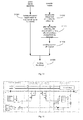
- the integrated control system includes: a power battery; a high-voltage distribution box connected with the power battery; an integrated driving and charge-discharge controller, connected with the power battery via the high-voltage distribution box, and connected with a motor and a charge-discharge socket respectively, and configured to drive the motor when the electric vehicle is in a driving mode, and to control to charge and discharge the power battery via the charge-discharge socket when the electric vehicle is in a charge-discharge mode; an auxiliary high-voltage element connected with the power battery via the high-voltage distribution box; a first DC/DC module connected with the power battery via the high-voltage distribution box; and a controller connected with the high-voltage distribution box and configured to control the high-voltage distribution box so as to perform a pre-charging via the high-voltage distribution box before the integrated driving and charge-discharge controller, the auxiliary high-voltage element and the first DC
- a unified switching between respective operation modes of the system can be implemented according to practical requirements of different operation modes, thus implementing a coordination control to separated systems in the vehicle and having a high compatibility.
- a heat dissipation requirement can be satisfied when the system works at a high power, thus satisfying different functional requirements, expanding requirement of the electric vehicle, and having a good adaptability.
- the system implements the compatibility for the driving, charging and discharging requirements and satisfies the requirement of high power output.
- embodiments of a second aspect of the present disclosure provide an electric vehicle including the above mentioned integrated control system.
- a unified switching between respective operation modes of the system can be implemented according to practical requirements of different operation modes, thus implementing a coordination control to separated systems in the vehicle and having a high compatibility.
- a heat dissipation requirement can be satisfied when the system works at a high power, thus satisfying different function requirements, expanding requirement of the electric vehicle, and having a good adaptability.
- the system implements the compatibility for the driving, charging and discharging requirements and satisfies the requirement of high power output.
- a structure in which a first feature is "on" a second feature may include an embodiment in which the first feature directly contacts the second feature, and may also include an embodiment in which an additional feature is formed between the first feature and the second feature so that the first feature does not directly contact the second feature.
- the terms “mounted,” “connected,” and “coupled” and variations thereof are used broadly and encompass such as mechanical or electrical mountings, connections and couplings, also can be inner mountings, connections and couplings of two components, and further can be direct and indirect mountings, connections, and couplings, which can be understood by those skilled in the art according to the particular embodiment of the present disclosure.
- an integrated control system for an electric vehicle includes a power battery 10, a high-voltage distribution box 90, an auxiliary high-voltage element, a first DC/DC module 300, an integrated driving and charge-discharge controller 70 and a controller 80.
- the high-voltage distribution box 90 is connected with the power battery 10.
- the integrated driving and charge-discharge controller 70 is connected with the power battery 10 via the high-voltage distribution box 90, and connected with a motor and a charge-discharge socket, respectively.
- the integrated driving and charge-discharge controller 70 is configured to drive the motor when the electric vehicle is in a driving mode, and to control to charge and discharge the power battery via the charge-discharge socket when the electric vehicle is in a charge-discharge mode.
- the auxiliary high-voltage element is connected with the power battery 10 via the high-voltage distribution box 90.
- the first DC/DC module 300 is connected with the power battery 10 via the high-voltage distribution box 90.
- the controller 80 is connected with the high-voltage distribution box 90, and configured to control the high-voltage distribution box 90 so as to perform a pre-charging via the high-voltage distribution box 90 before the integrated driving and charge-discharge controller 70, the auxiliary high-voltage element and the first DC/DC module are powered on.
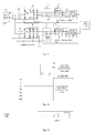
- the high-voltage distribution box 90 includes: a first pre-charging control module and a first switch connected in parallel with the first pre-charging control module, in which the first pre-charging control module has a first terminal connected with a first terminal of the power battery and a second terminal connected with a first terminal of the integrated driving and charge-discharge controller, and the first switch K1 has a first terminal connected with the first terminal of the power battery and a second terminal connected with the first terminal of the integrated driving and charge-discharge controller; a second pre-charging control module and a second switch K2 connected in parallel with the second pre-charging control module, in which the second pre-charging control module has a first terminal connected with the first terminal of the power battery and a second terminal connected with a first terminal of the first DC/DC module 300, and the second switch K2 has a first terminal connected with the first terminal of the power battery and a second terminal connected with the first terminal of the first DC/DC module; a third pre-charging control module and a third switch K3
- Fig. 5 three pre-charging resistors are used together with the switches K11, K21 and K31 in the pre-charging circuit. According to the actual conditions, if the requirement to the pre-charging time is low and the requirement to the cost and structure is high, these three pre-charging resistors can be merged into one pre-charging resistor, which implements the same function by setting different pre-charging time and dead-time with the power battery management system software.
- the controller controls to pre-charge the integrated driving and charge-discharge controller via the first pre-charging control module and turns on the fourth switch K4; when a bus voltage of the integrated driving and charge-discharge controller is a predetermined multiple of a voltage of the power battery, the controller controls the first pre-charging control module to turn off and turns on the first switch.
- the controller further controls to pre-charge the auxiliary high-voltage element via the third pre-charging control module; and when a bus voltage of the auxiliary high-voltage element is a predetermined multiple of the voltage of the power battery, the controller controls the third pre-charging control module to turn off and turns on the third switch K3.
- the controller When the electric vehicle is in the driving mode and the third switch K3 is turned on, the controller further controls to pre-charge the first DC/DC module 300 via the second pre-charging control module; and when a bus voltage of the first DC/DC module 300 is a predetermined multiple of the voltage of the power battery 10, the controller controls the second pre-charging control module to turn off and turns on the second switch K2.
- Driving mode a vehicle starting system sends a starting instruction
- the power battery management system 10 controls the high-voltage distribution system to execute corresponding operations after detecting that a status of the power battery is good.
- the contactor K5 at a cathode of the power battery is first turned on, and then the main pre-charging contactor K11 is turned on, so as to pre-charge the driving and charge-discharge controller.
- the integrated driving and charge-discharge controller detects the power bus voltage and gives a feedback to the power battery management system.
- the power battery management system detects that the bus voltage of the integrated driving and charge-discharge controller reaches 90% of the voltage of the power battery (or a difference between the bus voltage of the integrated driving and charge-discharge controller and the voltage of the power battery is less than 50V), it determines that the pre-charging is completed, controls the main contactor K1 to turn on, controls the main pre-charging contactor K11 to turn off, and sends states of the contactors and an instruction indicating that the pre-charging is completed and the driving is allowed. After receiving the above states and instruction and determining that the bus voltage is within a normal working voltage range, the driving and charge-discharge controller drives the vehicle according to signals such as a throttle depth signal.
- the power battery management system controls the auxiliary pre-charging contactor K31 to turn on, so as to pre-charge devices such as EPS controller and air compressor controller. These devices such as EPS controller detect and feed back the bus voltage thereof to the power battery management system.
- the power battery management system detects that the bus voltage reaches 90% of the voltage of the power battery (or a difference between the bus voltage and the voltage of the power battery is less than 50V)
- it determines that the pre-charging is completed controls the auxiliary contactor K3 to turn on, controls the auxiliary pre-charging contactor K31 to turn off, and sends states of corresponding contactors and an instruction indicating that the pre-charging is completed.
- the pre-charging of the auxiliary power circuit is completed.
- the power battery management system controls the DC pre-charging contactor K21 to turn on, so as to pre-charge the DC/DC inverter.
- the DC/DC inverter detects and feeds back the bus voltage thereof to the power battery management system.
- the power battery management system detects that the bus voltage of the DC/DC inverter reaches 90% of the voltage of the power battery (or a difference between the bus voltage of the DC/DC inverter and the voltage of the power battery is less than 50V)
- it determines that the pre-charging is completed controls the DC contactor K2 to turn on, controls the DC pre-charging contactor K21 to turn off, and sends states of corresponding contactors and an instruction indicating that the pre-charging is completed.
- the high-voltage distribution system completes the power distribution.
- Charge-discharge mode first, the driving and charge-discharge controller enters the charge-discharge mode according to corresponding vehicle settings or connecting the vehicle with the charging gun, and sends a message indicating that the charge or discharge is prepared.
- the power battery management system detects whether the state of the power battery is suitable for the charge or discharge after receiving the message, and if yes, starts to perform the pre-charging.
- the contactor K5 at a cathode of the power battery is first turned on, and then the main pre-charging contactor K11 is turned on, so as to pre-charge the driving and charge-discharge controller.
- the driving and charge-discharge controller detects and feeds back the power bus voltage to the power battery management system.
- the power battery management system When the power battery management system detects that the bus voltage of the driving and charge-discharge controller reaches 90% of the voltage of the power battery (or a difference between the bus voltage of the driving and charge-discharge controller and the voltage of the power battery is less than 50V), it determines that the pre-charging is completed, controls the main contactor K1 to turn on, controls the main pre-charging contactor K11 to turn off, and sends states of corresponding contactors and an instruction indicating that the pre-charging is completed and the charge-discharge is allowed. Subsequently, the power battery management system controls the DC pre-charging contactor K21 to turn on, so as to pre-charge the DC/DC inverter.
- the DC/DC inverter detects and feeds back the bus voltage thereof to the power battery management system.
- the power battery management system detects that the bus voltage of the DC/DC inverter reaches 90% of the voltage of the power battery (or a difference between the bus voltage of the DC/DC inverter and the voltage of the power battery is less than 50V)
- it determines that the pre-charging is completed controls the DC contactor K2 to turn on, controls the DC pre-charging contactor K21 to turn off, and sends states of corresponding contactors and the instruction indicating that the pre-charging is completed.
- the high-voltage distribution system completes the power distribution.
- the integrated control system for the electric vehicle may further include a cooling module.
- the cooling module is configured to cool the integrated control system.
- the BCM guards security of the whole vehicle and starts the starting system for low-voltage system to send starting-related instructions to related modules such as the power battery management system and the integrated driving and charge-discharge controller 70.
- the power battery management system enters the driving mode after receiving the starting instruction, and turns on the cathode contactor K5 and the pre-charging contactors such as K11, K21 and K31 in Fig. 5 after detecting that the state of the power battery is good, so as to start to pre-charge respective high-voltage electric appliances (such as the integrated driving and charge-discharge controller 70, the DC-DC 30, the air conditioner, and EPS) and to send corresponding voltages of the high-voltage circuits.
- respective high-voltage electric appliances such as the integrated driving and charge-discharge controller 70, the DC-DC 30, the air conditioner, and EPS
- the power battery management system determines that the voltage of each high-voltage electric appliance satisfies the pre-charging completion condition, it controls corresponding contactors to turn on so as to switch on the high-voltage power circuits.
- DC-DC 30 inverts the high-voltage DC of the power battery into low-voltage current for supplying to low-voltage electric appliances and the storage battery in the vehicle.
- the auxiliary controller samples vehicle signals and controls the cooling system to work.
- the driving and charge-discharge controller synthetically processes the vehicle signals sampled by the auxiliary controller, such as an accelerator pedal signal, a brake pedal signal and a gear signal, to compute corresponding desired torque value of the motor, so as to control the motor to drive the vehicle by inverting DC into AC.
- a display system such as a combination meter displays a running state of the vehicle.
- the integrated driving and charge-discharge controller 70 detects the connection between the charging gun and the vehicle, outputs corresponding connection signal to the BCM, the BCM controls to start the low-voltage charging system, and sends corresponding state.
- the power battery management system enters the charging mode according to the state instructed by the BCM, and implements corresponding operations according to state of the driving and charge-discharge controller after detecting that the state of the power battery is good.
- the driving and charge-discharge controller determines whether the charging connection is completed by detecting an interaction between the charging gun and the charging apparatus, sends the corresponding state signal to the power battery management system after determining that the charging connection is completed.
- the power battery management system After receiving the corresponding state signal, the power battery management system starts to turn on the pre-charging contactors K11 and K21 and the cathode contactor K5 in Fig. 5 to perform the pre-charging.
- Corresponding integrated driving and charge-discharge controller 70 and DC-DC 30 starts to send voltage values of the power circuits.
- the power battery management system determines that voltage values of respective high-voltage electric appliances satisfy the pre-charging completion condition, it controls corresponding contactors to turn on to switch on the high-voltage power circuits, and sends corresponding state information.
- DC-DC 30 inverts the high-voltage DC of the power battery into the low-voltage current for supplying to low-voltage electric appliances and the storage battery in the vehicle.
- the driving and charge-discharge controller starts the power module after detecting that the high-voltage power circuit is connected and the voltages thereof are normal, the auxiliary controller detects the state of the charging interface and controls the cooling system to work, and the combination meter of the display system displays charging information of the vehicle.
- a discharging instruction is sent by the combination meter or other trigger signals.
- the power battery management system enters the discharging mode according to the instruction, and turns on the pre-charging contactors K11, K21 and the cathode contactor K5 in Fig. 5 to perform the pre-charging after detecting that the state of the power battery is good.
- Corresponding integrated driving and charge-discharge controller 70 and DC-DC 30 start to send voltage values of the power circuits.
- the power battery management system determines that voltage values of respective high-voltage electric appliances satisfy the pre-charging completion condition, it controls corresponding contactors to turn on to switch on the high-voltage power circuits, and sends corresponding state information.
- DC-DC 30 inverts the high-voltage DC of the power battery into the low-voltage current for supplying to low-voltage electric appliances and the storage battery in the vehicle.
- the driving and charge-discharge controller detects the connection state between the discharging connector and the charging gun, and starts to discharge externally according to set discharging requirements after detecting that the connection between the power circuit and the discharging apparatus is completed.
- the combination meter displays the discharging information of the vehicle.
- a power system for an electric vehicle includes a power battery 10, a charge-discharge socket 20, a bidirectional DC/DC module 30, a driving control switch 40, a bidirectional DC/AC module 50, a motor control switch 60, a charge-discharge control module 70 and a controller module 80.
- the bidirectional DC/DC module 30 has a first DC terminal a1 connected with a first terminal of the power battery 10 and a second DC terminal a2 connected with a second terminal of the power battery 10.
- the first DC terminal a1 is a common DC terminal for an input to and an output from the bidirectional DC/DC module 30.
- the driving control switch 40 has a first terminal connected with the second terminal of the power battery 10 and a second terminal connected with a third DC terminal a3 of the bidirectional DC/DC module 30.
- the driving control switch is the same as the switch K4 in Fig. 5 .
- the bidirectional DC/AC module 50 has a first DC terminal b1 connected with the second terminal of the driving control switch 40 and a second DC terminal b2 connected with the first terminal of the power battery 10.
- the motor control switch 60 has a first terminal connected with an AC terminal c of the bidirectional DC/AC module 50 and a second terminal connected with a motor M.
- the charge-discharge control module 70 has a first terminal connected with the AC terminal c of the bidirectional DC/AC module 50 and a second terminal connected with the charge-discharge socket 20.
- the controller module 80 is connected with the driving control switch 40, the motor control switch 60 and the charge-discharge control module 70 respectively, and configured to control the driving control switch 40, the motor control switch 60 and the charge-discharge control module 70 according to a current operation mode of the power system.
- the current operation mode of the power system may include a driving mode and a charge-discharge mode.
- the controller module 80 controls the driving control switch 40 to turn on to stop the bidirectional DC/DC module 30, controls the motor control switch 60 to turn on to drive the motor M normally, and controls the charge-discharge control module to turn off.
- the motor control switch 60 in Fig. 5 includes three switches connected with a three-phase input to the motor, in other embodiments, the motor control switch 60 may also comprise two switches connected with a two-phase input to the motor, or even one switch, as long as the control on the motor may be realized. Therefore, other embodiments will not be described in detail herein.
- the controller module 80 controls the driving control switch 40 to turn off to start the bidirectional DC/DC module 30, controls the motor control switch 60 to turn off to remove the motor M, and controls the charge-discharge control module to turn on, such that an external power source may charge the power battery 10 normally.
- the first DC terminal a1 and the third DC terminal a3 of the bidirectional DC/DC module 30 are connected with a positive terminal and a negative terminal of a DC bus respectively.
- the power system for the electric vehicle further includes a first pre-charging control module 101.
- the first pre-charging control module 101 has a first terminal connected with the second terminal of the power battery 10 and a second terminal connected with the second DC terminal a2 of the bidirectional DC/DC module 30, and configured to pre-charge a capacitor C1 in the bidirectional DC/DC module 30 and a bus capacitor C0 connected between the first DC terminal a1 and the third DC terminal a3 of the bidirectional DC/DC module 30.
- the first pre-charging control module 101 includes a first switch K1, a first resistor R1 and a second switch K2. In one embodiment, the first switch K1 is the same as the switch K11 in Fig.
- the second switch K2 is the same as the switch K1 in Fig. 5 .
- the first switch K1 has a first terminal connected with the second DC terminal a2 of the bidirectional DC/DC module 30.
- the first resistor R1 has a first terminal connected with a second terminal of the first switch K1 and a second terminal connected with the second terminal of the power battery 10.
- the second switch K2 is connected in parallel with the first resistor R1 and the first switch K1 which are connected in series.
- the controller module 80 controls the first switch K1 to turn on to pre-charge the capacitor C1 in the bidirectional DC/DC module 30 and the bus capacitor C0; and when a voltage across the bus capacitor C0 is a predetermined multiple of a voltage of the power battery 10, the controller module 80 controls the first switch K1 to turn off and controls the second switch K2 to turn on.
- the bidirectional DC/DC module 30 includes a first switching transistor Q1, a second switching transistor Q2, a first diode D1, a second diode D2, a first inductor L1 and a first capacitor C1.
- the first switching transistor Q1 and the second switching transistor Q2 are connected in series, and connected between the first DC terminal a1 and the third DC terminal a3 of the bidirectional DC/DC module 30, and controlled by the controller module 80.
- a first node A is defined between the first switching transistor Q1 and the second switching transistor Q2.
- the first diode D1 is connected with the first switching transistor Q1in inverse-parallel.
- the second diode D2 is connected with the second switching transistor Q2 in inverse-parallel.
- the first inductor L1 has a first terminal connected with the first node A and a second terminal connected with the second terminal of the power battery 10.
- the first capacitor C1 has a first terminal connected with the second terminal of the first inductor L1 and a second terminal connected with the first terminal of the power battery 10.
- the power system for the electric vehicle further includes a leakage current reducing module 102.
- the leakage current reducing module 102 is connected between the first DC terminal a1 and the third DC terminala3 of the bidirectional DC/DC module 30.
- the leakage current reducing module 102 includes a second capacitor C2 and a third capacitor C3.
- the second capacitor C2 has a first terminal connected with a first terminal of the third capacitor C3 and a second terminal connected with the first DC terminal a1 of the bidirectional DC/DC module 30,
- the third capacitor C3 has a second terminal connected with the third DC terminala3 of the bidirectional DC/DC module 30, and a second node B is defined between the second capacitor C2 and the third capacitor C3.
- the leakage current reducing module 102 is connected between the positive terminal and the negative terminal of the DC bus, thus reducing the leakage current effectively.
- the leakage current reducing module 102 includes two capacitors C2 and C3 of the same type, the capacitor C2 is connected between the negative terminal of the DC bus and a three-phase AC neutral point potential, the capacitor C3 is connected between the positive terminal of the DC bus and the three-phase AC neutral point potential, and a high-frequency current may be fed back to a DC side when the power system operates, thus effectively reducing a high-frequency leakage current generated when the power system operates.
- the power system for the electric vehicle further includes a filtering module 103, a filtering control module 104, an EMI-filter module 105 and a second pre-charging control module 106.
- the filtering module 103 is connected between the bidirectional DC/AC module 50 and the charge-discharge control module 70.
- the filtering module 103 includes inductors L A , L B , L C and capacitors C4, C5, C6, and the bidirectional DC/AC module 50 may comprise six IGBTs (insulated gate bipolar transistor), a connection point between an upper IGBT and a lower IGBT is connected with the filtering module 103 and the motor control switch 60 via a power bus respectively.
- IGBTs insulated gate bipolar transistor
- the filtering control module 104 is connected between the second node B and the filtering module 103, and controlled by the controller module 80.
- the controller module 80 controls the filtering control module 104 to turn off.
- the filtering control module 104 may be a contactor relay, and consists of a contactor K10.
- the EMI-filter module 105 is connected between the charge-discharge socket 20 and the charge-discharge control module 70. It should be noted that, the position of the contactor K10 in Fig. 8 is merely exemplary. In other embodiments, the contactor K10 may be located at other positions, provided that the filtering module 103 may be turned off using the contactor K10. For example, in another embodiment, the contactor K10 may also be connected between the bidirectional DC/AC module 50 and the filtering module 103.
- the second pre-charging control module 106 is connected with the charge-discharge control module 70 in parallel and configured to pre-charge capacitors C4, C5, C6 in the filtering module 103.
- the second pre-charging control module 106 includes three resistors R A , R B , R C and a three-phase pre-charging switch K9.
- the charge-discharge control module 70 includes a three-phase switch K8 and/or a single-phase switch K7 configured to implement a three-phase charge-discharge or a single-phase charge-discharge.
- the controller module 80 when the power system starts, controls the first switch K1 to turn on to pre-charge the first capacitor C1 in the bidirectional DC/DC module 30 and the bus capacitor C0; and when the voltage across the bus capacitor C0 is a predetermined multiple of the voltage of the power battery 10, the controller module 80 controls the first switch K1 to turn off and controls the second switch K2 to turn on.
- the bidirectional DC/DC module 30 and the large-capacity bus capacitor C0 directly connected between power buses (i.e.
- DC buses constitute main components for implementing a battery activation technology at a low temperature, and are configured to transfer the electric energy of the power battery 10 to the large-capacity bus capacitor C0 via the bidirectional DC/DC module 30, and to transfer the electric energy stored in the large-capacity bus capacitor C0 to the power battery 10 via the bidirectional DC/DC module 30 (i.e. charge the power battery 10). Therefore, the circulating charge and discharge of the power battery 10 makes the temperature of the power battery 10 rise to an optimum operation temperature range.
- the controller module 80 controls the driving control switch 40 to turn on to stop the bidirectional DC/DC module 30, controls the motor control switch 60 to turn on to drive the motor M normally, and controls the charge-discharge control module 70 to turn off.
- a DC from the power battery 10 is inverted into an AC by means of the bidirectional DC/AC module 50, and the AC is transmitted to the motor M.
- the motor M can be controlled by a revolving transformer decoder technology and a space vector pulse width modulation (SVPWM) control algorithm.
- SVPWM space vector pulse width modulation
- the controller module 80 controls the driving control switch 40 to turn off to start the bidirectional DC/DC module 30, controls the motor control switch 60 to turn off to remove the motor M, and controls the charge-discharge control module 70 to turn on, such that an external power source such as a three-phase power source or a single-phase power source may charge the power battery 10 via the charge-discharge socket 20 normally.
- a controllable rectification function may be performed with aid of the bidirectional DC/AC module 50, and the in-vehicle power battery 10 may be charged by the single-phase power source and/or the three-phase power source with aid of the bidirectional DC/AC module 50 and the bidirectional DC/DC module 30.
- the electric vehicle can be charged with a high power by means of a civil or industrial AC grid, such that a user may perform the charge efficiently, promptly, anytime and anywhere, thus saving a charging time.
- a constant-voltage control device or a constant-current control device is not required, thus saving a space and a cost and having a wide battery operation voltage range.
- the controller module 80 includes a control panel 201 and a driving panel 202.
- a control module on the control panel 201 includes two high-speed digital signal processing chips (i.e., DSP1 and DSP2).
- the control module on the control panel 201 isconnected and communicated with a vehicle information interface 203.
- the control module on the control panel 201 is configured to receive a bus voltage sampling signal, an IPM protection signal and an IGBT temperature sampling signal output from a driving module on the driving panel 202, and to output a pulse width modulation (PWM) signal to the driving module.
- PWM pulse width modulation
- the DSP1 is mainly configured to control and the DSP2 is configured to sample information.
- a sampling unit in the DSP1 outputs sampling signals including a throttle signal, a bus voltage sampling signal, a brake signal, a DC-side voltage sampling signal, a Hall V-phase signal of a current of the motor M, a Hall W-phase signal of the current of the motor M, a Hall U-phase signal of a charging control current, a Hall V-phase signal of the charging control current, a Hall W-phase signal of the charging control current, a Hall signal of a DC current, a U-phase signal of an inverter voltage, a V-phase signal of the inverter voltage, a W-phase signal of the inverter voltage, a U-phase signal of a grid voltage, a V-phase signal of the grid voltage, a W-phase signal of the grid voltage, an inverting U-phase capturing signal, a grid U-phase capturing signal, etc.
- a switch control unit in the DSP1 outputs an A-phase switch signal of the motor, a B-phase switch signal of the motor, an A-phase switch signal of the grid, a B-phase switch signal of the grid, a C-phase switch signal of the grid, a three-phase pre-charging switch signal, a contactor relay signal, etc.
- a driving unit in the DSP1 outputs an A-phase PWM1 signal, an A-phase PWM2 signal, a B-phase PWM1 signal, a B-phase PWM2 signal, a C-phase PWM1 signal, a C-phase PWM2 signal, a DC-phase PWM1 signal, a DC-phase PWM2 signal, an IPM protection signal, etc.
- the DSP1 also has other functions such as a revolving signal output control function, a serial communication function, a hardware protection function, a CAN communication function and a gear control function.
- a sampling unit in the DSP2 outputs a monitoring signal for a power supply, a monitoring signal for a power source, a first throttle signal, a second brake signal, a second throttle signal, a first brake signal, an analog temperature signal of the motor, a leakage sensor signal, a temperature signal of a radiator, a temperature sampling signal of an inductor at the DC side, a temperature sampling signal of a V-phase inductor, a temperature sampling signal of a U-phase inductor, a temperature sampling signal of a W-phase inductor, a discharging PWM voltage sampling signal, a read signal of a tilt sensor, a chip select signal of the tilt sensor, a W-phase IGBT temperature sampling signal, a U-phase IGBT temperature sampling signal, a buck-boost-phase IGBT
- a charge-discharge control unit in the DSP2 outputs a charge-discharge switch signal, a dormant signal, a discharging PWM signal, a BMS signal of a battery manager, a charge-discharge output control signal, a CP signal, a CC signal, etc.
- the DSP2 also has other functions such as a CAN communication function and a serial communication function.
- the power system for the electric vehicle combines a motor diving function, a vehicle control function, an AC charge function, a connected-grid power supplying function, an off-grid on-load function and a vehicle-to-vehicle charging function.
- the power system does not combine various functional modules simply and physically, but based on a motor driving control system, makes use of some peripheral devices to implement the diversification of the functions of the system, thus saving space and cost to a maximum extent and improving a power density.
- a DC from the power battery 10 is inverted into an AC by means of the bidirectional DC/AC module 50, and the AC is transmitted to the motor M.
- the motor M can be controlled by a revolving transformer decoder technology and a space vector pulse width modulation (SVPWM) control algorithm.
- SVPWM space vector pulse width modulation
- a process of determining a function of the power system comprises the following steps.
- the power system is powered.
- step 902 it is determined whether there is a charge connection signal.
- step 903 If there is the charge connection signal, step 903 is executed; otherwise, step 904 is executed.
- the power system enters a charge-discharge control process.
- a throttle signal, a gear signal and a brake signal are also determined.
- the charge connection signal i.e. a CC signal
- the power system enters the charge-discharge control process.
- the power system enters a vehicle control process.
- the controller module 80 controls the motor control switch 60 to turn on, and informs the battery manager 108 via a CAN communication to control the high-voltage distribution box 90 to pre-charge the first capacitor C1 and the bus capacitor C0, and then the controller module 80 detects a bus voltage 187 and determines whether the pre-charge is successful. If the pre-charge is successful, the controller module 80 informs the battery manager 108 to control the driving control switch 40 to turn on, such that the power system enters the driving mode; and the controller module 80 samples the vehicle information and drives the motor M via a comprehensive judgment process.
- the motor driving control function is performed as follows. As shown in Fig. 12 , the controller module 80 sends a PWM signal so as to control the bidirectional DC/AC module 50 to invert the DC from the power battery 10 into the AC and transmit the AC to the motor M. Subsequently, the controller module 80 solves a rotor location via a revolver and samples the bus voltage and B-phase and C-phase currents of the motor so as to make the motor M operate precisely. In other words, the controller module 80 adjusts the PWM signal according to the B-phase and C-phase current signals of the motor sampled by a current sensor and feedback information from the revolver, such that the motor M may operate precisely.
- an accelerating function, a decelerating function and an energy feedback function can be implemented, such that the whole vehicle can operates safely and reliably under any condition, thus ensuring the safety, dynamic performance and comfort of the vehicle.
- a process of determining whether to start the charge-discharge function of the power system comprises the following steps.
- step 1101 the physical connection between the charge-discharge connection device and the charge-discharge socket is finished, and a power source is normal.
- a power supply apparatus determines whether the charge connection signal (i.e. the CC signal) is normal, if yes, step 1103 is executed; if no, step 1102 is re-executed for another determining.
- the charge connection signal i.e. the CC signal
- the power supply apparatus determines whether a voltage at a CP detecting point is 9V. If yes, step 1106 is executed; if no, step 1102 is re-executed for another determining.
- 9V is a predetermined value and is just exemplary.
- step 1104 the controller module determines whether the charge connection signal (i.e. the CC signal) is normal. If yes, step 1105 is executed; if no, step 1104 is re-executed for another determining.
- the charge connection signal i.e. the CC signal
- the charge connection signal and a charge indicator lamp signal are pulled down.
- the power system enters the charge-discharge function.
- a process of controlling the power system in a charging mode comprises following steps.
- step 1201 it is determined whether the power system is completely started after being powered. If yes, step 1202 is executed; if no, step 1201 is re-executed for another determining.
- a resistance at a CC (charge connection) detecting point is detected, so as to determine a capacity of the charge connection device.
- step 1203 it is determined whether a PWM signal with a constant duty ratio is detected at the CP detecting point. If yes, step 1204 is executed; if no, step 1205 is executed.
- step 1204 a message indicating the charge connection is normal and the charge is prepared is sent out and a message indicating BMS permits the charge and a charge contactor is turned on is received, and step 1206 is executed.
- the controller module turns on an internal switch.
- step 1207 it is determined whether an external charging apparatus does not send a PWM wave in a predetermined time such as 1.5 seconds. If yes, step 1208 is executed; if no, step 1209 is executed.
- step 1208 it is determined that the external charging apparatus is an external national standard charging post and the PWM wave is not sent out during the charge.
- the PWM wave is sent to the power supply apparatus.
- step 1210 it is determined whether an AC input is normal in a predetermined time such as 3 seconds. If yes, step 1213 is executed; if no, step 1211 is executed.
- a fault occurs in an AC external charging apparatus.
- the fault is processed.
- the power system enters the charging stage.
- the capacity of the charge connection device may be determined by detecting a voltage of the CC signal, and it is determined whether the charge-discharge connection device is connected totally by detecting the CP signal. After it is determined that the charge-discharge connection device is connected totally, the message indicating the charge connection is normal and the charge is prepared is sent out, and the battery manager 108 controls the high-voltage distribution box 90 to turn on the first switch K1 so as to pre-charge the first capacitor C1 and the bus capacitor C0. After the pre-charge, the first switch K1 is turned off and the second switch K2 is turned on.
- the controller module 80 receives the message indicating BMS permits the charge and the second switch K2 is turned on, and thus the charge-discharge is prepared, i.e., functions such as the AC charge function (G to V, grid to vehicle), the off-grid on-load function (V to L, vehicle to load), the grid connection function (V to G, vehicle to grid) and the vehicle-to-vehicle charging function (V to V, vehicle to vehicle), may be set via the dashboard.
- functions such as the AC charge function (G to V, grid to vehicle), the off-grid on-load function (V to L, vehicle to load), the grid connection function (V to G, vehicle to grid) and the vehicle-to-vehicle charging function (V to V, vehicle to vehicle) may be set via the dashboard.
- the controller module 80 determines a minimum charging current among a maximum charging current allowed by the battery manager 80, a maximum power supply current of the power supply apparatus and a rated current of the charge-discharge connection device (i.e. the charge-discharge socket 20), and selects relevant charging parameters automatically. Moreover, the power system samples the AC transmitted by the power supply apparatus via a grid voltage sampling 183, so as to obtain a sampling value. The controller module 80 solves an effective value of an AC voltage according to the sampling value and determines an AC frequency by capturing. A type of the AC can be determined according to the effective value of the AC voltage and the AC frequency, and control parameters can be selected according to the type of the AC.
- the controller module 80 controls the three-phase pre-charging switch K9 in the second pre-charging module 106 and the contactor K10 in the filtering control module 104 to turn on, so as to charge the bus capacitor C0 at a PWM DC side.
- the controller module 80 samples the bus voltage 187, i.e. the voltage across the bus capacitor C0.
- the controller module 80 controls the three-phase switch K8 to turn on and the three-phase switch K9 to turn off.
- the controller module 80 sends the PWM signal to control the bidirectional DC/AC module 50 to rectify an AC to obtain a DC.
- the controller module 80 controls the bidirectional DC/DC module 30 to adjust the voltage of the DC according to the voltage of the power battery 10, and finally the DC is transmitted to the power battery 10.
- the controller module 80 performs a closed-loop current control on the power system according to the determined target charging current and phase currents fed back from a current sampling 184, and finally the in-vehicle power battery 10 is charged.
- a controllable rectification function may be performed with aid of the bidirectional DC/AC module 50, and the in-vehicle power battery 10 may be charged by the single-phase power source and/or the three-phase power source with aid of the bidirectional DC/DC module 30 and the bidirectional DC/AC module 50.
- the power system When the power system receives a V to L instruction from the dashboard, it is first determined whether a state of charge (SOC) of the power battery 10 is in an allowable discharging range. If yes, a type of an output voltage is selected according to the V to L instruction. A maximum output power is selected intelligently and controls parameters are given according to the rated current of the charge-discharge connection device, and then the power system enters a control process. First, the controller module 80 controls the three-phase switch K8 and the contactor K10 to turn on and sends the PWM signal to control the bidirectional DC/DC module 30 to adjust the voltage of the DC according to the voltage of the power battery and a given output voltage.
- SOC state of charge
- the DC is transmitted to the bidirectional DC/AC module 50 to be inverted into the AC, and electric apparatuses may be powered by the AC directly via a dedicated charge socket.
- the controller module 80 performs the adjustment according to a feedback of the voltage sampling 183, so as to ensure safe and reliable operation of a load.
- the DC/DC voltage conversion is performed according to the voltage of the power battery, and the DC is inverted into the AC by means of the bidirectional DC/AC module 50, thus outputting a stable single-phase/three-phase AC voltage.
- the controller module 80 controls the three-phase switch K8 and the contactor K10 to turn on and sends the PWM signal to control the bidirectional DC/DC module 30 to adjust the voltage of the DC according to the voltage of the power battery and the given output voltage. Then, the DC is transmitted to the bidirectional DC/AC module 50 to be inverted into the AC.
- the controller module 80 performs the closed-loop current control on the power system according to a predetermined target discharging current and the phase currents fed back from the current sampling 184, so as to implement the grid connection power supplying.
- the DC/DC voltage conversion is performed according to the voltage of the power battery, and the DC is inverted into the AC by means of the bidirectional DC/AC module 50, and thus the vehicle supplies the single-phase/three-phase AC to the grid.
- the V to V function requires a dedicated connection plug.
- the power system determines that the charge connection signal(i.e. CC signal) is effective and the connection plug is a dedicated charge plug for the V to V function by detecting a level of the connection plug, the power system is prepared for an instruction from the dashboard. For example, assuming vehicle A charges vehicle B, the vehicle A is set in a discharging state, i.e. the vehicle A is set to perform the off-grid on-load function, the vehicle B is set in an AC charging state. The controller module in vehicle A sends the message indicating "the charge connection is normal" and "the charge is prepared" to the battery manager.
- the battery manager controls a charge-discharge circuit to perform the pre-charging, and sends the message indicating the charge is permitted and the charging contactor is turned on to the controller module after the pre-charging is finished. Then, the power system performs the discharging function and sends the PWM signal. After the vehicle B receives the charging instruction, the power system therein detects a CP signal which determines that the vehicle A is prepared to supply power, and the controller module 80 sends a normal connection message to the battery manager. After receiving the message, the battery manager 108 finishes the pre-charging process and informs the controller module that the whole power system is prepared for the charge. Then, the vehicle-to-vehicle charging function (V to V) starts, and thus vehicles can charge each other.
- V to V vehicle-to-vehicle charging function
- the vehicle is set in an AC power output state and sends the CP signal by simulating a charging box, so as to communicate with the vehicle to be charged.
- the DC/DC voltage conversion is performed according to the voltage of the power battery, and the DC is inverted into the AC by means of the bidirectional DC/AC module 50, and thus the vehicle can charge another vehicle with the single-phase/three-phase AC.
- a process of controlling the power system when the charging of the electric vehicle is finished comprises the following steps.
- step 1301 the power supply apparatus turns off a power supply switch to stop outputting the AC, and step 1305 is executed.
- step 1302 the controller module stops the charge and performs the unloading, and step 1303 is executed.
- step 1303 after the unloading is finished, the internal switch is turned off and a charge finishing message is sent out.
- a power-off request is sent out.
- a power supply apparatus 301 is connected with a vehicle plug 303 of an electric vehicle 1000 via a power supply plug 302, so as to charge the electric vehicle 1000.
- the power system of the electric vehicle 1000 detects a CP signal at a detecting point 3 and detects a CC signal at a detecting point 4, and the power supply apparatus 301 detects the CP signal at a detecting point 1 and detects the CC signal at a detecting point 2.
- the internal switches S2 in both the power supply plug 302 and the vehicle plug 303 are controlled to turn off.
- a plurality of power systems connected in parallel can be used in the electric vehicle to charge the power battery.
- two power systems connected in parallel are used to charge the power battery, and the two power systems use a common controller module.
- a charging system for the electric vehicle comprises a power battery 10, a first charging branch 401, a second charging branch 402 and a controller module 80.
- Each of the first charging branch 401 and the second charging branch 402 comprises a charge-discharge socket 20, a bidirectional DC/DC module 30, a bus capacitor C0, a bidirectional DC/AC module 50, a filtering module 103, a charge-discharge control module 70 and a second pre-charging module 106.
- each of the first charging branch 401 and the second charging branch 402 further includes a fuse FU.
- the power battery 10 is connected with the first charging branch 401 via the first pre-charging control module 101, and connected with the second charging branch 402 via the first pre-charging control module 101.
- the controller module 80 is connected with the first charging branch 401 and the second charging branch 402 respectively, and configured to control the grid to charge the power battery 10 via the first charging branch 401 and the second charging branch 402 respectively when receiving a charging signal.
- an embodiment of the present disclosure provides a method for controlling charging an electric vehicle.
- the method comprises following steps.
- a controller module when determining that a first charging branch is connected with a power supply apparatus via a charge-discharge socket and a second charging branch is connected with the power supply apparatus via the charge-discharge socket, a controller module sends a charge connection signal to a battery manager.
- step 2 after receiving the charge connection signal sent from the controller module, the battery manager detects and determines whether a power battery needs to be charged, if yes, a next step (step 3) is executed.
- the battery manager sends a charging signal to the controller module.
- the controller module controls the grid to charge the power battery via the first charging branch and the second charging branch respectively.
- the controller module controls the grid to charge the power battery via the first charging branch and the second charging branch respectively, such that a charging power of the electric vehicle is increased and a charging time is shortened greatly, thus implementing a fast charge and saving a time cost.
- the power system for the electric vehicle has a wide compatibility and performs a single-phase/three-phase switching function, and thus is adapted to various power grids of different countries.
- the charge-discharge socket 20 has a function of switching between two charging sockets (such as a United States standard charging socket and a European standard charging socket).
- the charge-discharge socket 20 includes a single-phase charging socket 501 such as the United States standard charging socket, a three-phase charging socket 502 such as the European standard charging socket and two high-voltage contactors K503 and K504.
- a CC terminal, a CP terminal and a CE terminal are common terminals for the single-phase charging socket 501 and the three-phase charging socket 502.
- the single-phase charging socket 501 has an L-phase wire and an N-phase wire connected with an A-phase wire and a B-phase wire of the three-phase charging socket 502 via the contactors K503 and K504 respectively.
- the controller module 80 controls the contactors K503 and K504 to turn on, such that the A-phase and B-phase wires of the three-phase charging socket 502 are connected with the L-phase and N-phase wires of the single-phase charging socket 501 respectively.
- the three-phase charging socket 502 does not operate, and instead of the L-phase and N-phase wires of the single-phase charging socket 501, the A-phase and B-phase wires of the three-phase charging socket 502 are connected with the charge plug, and thus the controller module 80 can perform the single-phase charge function normally.
- a standard 7-core socket is used and the single-phase switch K7 is added between the N-phase and B-phase wires.
- the controller module 80 controls the single-phase switch K7 to turn on so as to connect the B-phase wire with the N-phase wire.
- the A-phase and B-phase wires are used as the L-phase and N-phase wires respectively, and the connection plug should be a dedicated connection plug or a connection plug whose B-phase and C-phase wires are not used.
- the power system detects a voltage of the grid via the controller module 80 and determines the frequency and the single-phase/three-phase of the grid by calculation, so as to obtain the type of the grid. Then, the controller module 80 selects different control parameters according to a type of the charge-discharge socket 20 and the type of the grid. Furthermore, the controller module 80 controls the bidirectional DC/AC module 50 to rectify the AC controllably to obtain the DC and controls the bidirectional DC/DC module 30 to adjust the voltage of the DC according to the voltage of the power battery. Finally, the DC is transmitted to the power battery 10.
- an off-grid on-load charging socket includes two-core, three-core and four-core sockets connected with a charge plug, and is configured to output single-phase, three-phase and four-phase current.
- a unified switching between respective operation modes of the system can be implemented according to practical requirements of different operation modes, thus implementing a coordination control to separated systems in the vehicle and having a high compatibility.
- a heat dissipation requirement can be satisfied when the system works at high power, thus satisfying different function requirements, expanding requirement of the electric vehicle, and having a good adaptability.
- the system implements the compatibility for the driving, charging and discharging requirements and satisfies the requirement of high power output.
- Any procedure or method described in the flow charts or described in any other way herein may be understood to comprise one or more modules, portions or parts for storing executable codes that realize particular logic functions or procedures.
- advantageous embodiments of the present disclosure comprises other implementations in which the order of execution is different from that which is depicted or discussed, including executing functions in a substantially simultaneous manner or in an opposite order according to the related functions. This should be understood by those skilled in the art to which embodiments of the present disclosure belong.
- the logic and/or step described in other manners herein or shown in the flow chart, for example, a particular sequence table of executable instructions for realizing the logical function may be specifically achieved in any computer readable medium to be used by the instruction execution system, device or equipment (such as the system based on computers, the system comprising processors or other systems capable of obtaining the instruction from the instruction execution system, device and equipment and executing the instruction), or to be used in combination with the instruction execution system, device and equipment.
- the computer readable medium may be any device adaptive for including, storing, communicating, propagating or transferring programs to be used by or in combination with the instruction execution system, device or equipment.
- the computer readable medium comprise but are not limited to: an electronic connection (an electronic device) with one or more wires, a portable computer enclosure (a magnetic device), a random access memory (RAM), a read only memory (ROM), an erasable programmable read-only memory (EPROM or a flash memory), an optical fiber device and a portable compact disk read-only memory (CDROM).
- the computer readable medium may even be a paper or other appropriate medium capable of printing programs thereon, this is because, for example, the paper or other appropriate medium may be optically scanned and then edited, decrypted or processed with other appropriate methods when necessary to obtain the programs in an electric manner, and then the programs may be stored in the computer memories.
- each part of the present disclosure may be realized by the hardware, software, firmware or their combination.
- a plurality of steps or methods may be realized by the software or firmware stored in the memory and executed by the appropriate instruction execution system.
- the steps or methods may be realized by one or a combination of the following techniques known in the art: a discrete logic circuit having a logic gate circuit for realizing a logic function of a data signal, an application-specific integrated circuit having an appropriate combination logic gate circuit, a programmable gate array (PGA), a field programmable gate array (FPGA), etc.
- each function cell of the embodiments of the present disclosure may be integrated in a processing module, or these cells may be separate physical existence, or two or more cells are integrated in a processing module.
- the integrated module may be realized in a form of hardware or in a form of software function modules. When the integrated module is realized in a form of software function module and is sold or used as a standalone product, the integrated module may be stored in a computer readable storage medium.
- the storage medium mentioned above may be read-only memories, magnetic disks, CD, etc.
Abstract
Description
- The present disclosure relates to an electric vehicle field, and more particularly to an electric vehicle and an integrated control system of the electric vehicle.
- With the development of science and technology, fuel vehicles are being replaced by environment friendly and energy saving electric vehicles. However, the popularity of the electric vehicles encounters some problems, among which high driving mileage and fast charging technology has become major problems in the promotion of electric vehicles.
- Currently, large-capacity batteries are used in most electric vehicles. However, although these batteries may enhance a battery life of the electric vehicle, they make a charging time too long. Although a specialized DC (direct current) charging station may charge a battery quickly, problems such as high cost and large occupied area make the popularity of such an infrastructure encounter a certain difficulty. Moreover, because of a limited space of the vehicle, an in-vehicle charger may not satisfy the requirement of a charging power due to the limitation of its volume.
- A charging solution currently used in the market includes the following solutions.
- As shown in
Figs. 1-2 , an in-vehicle charging-discharging device in this solution mainly includes a three-phase power transformer 1', a three-phase bridge circuit 2' consisting of six thyristor elements, a constant-voltage control device AUR, and a constant-current control device ACR. However, this solution causes a serious waste of space and cost. - As shown in
Fig. 3 , an in-vehicle charging-discharging device in this solution includes two charging sockets 15', 16' to adapt to the single-phase/three-phase charging, which increases the cost. A motor driving loop includes a filtering module consisting of an inductor L1' and a capacitor C1'. When a motor is driven, a loss of a three-phase current is generated when it flows through the filtering module, which causes a waste of an electric quantity of a battery. With this solution, during the charging-discharging operation, an inverter 13'rectifies/inverts an AC (alternating current), and the voltage after the rectifying/inverting may not be adjusted, such that a battery operation voltage range is narrow. - Therefore, most AC charging technologies currently used in the market are a single-phase charging technology, which has disadvantages of low charging power, long charging time, large hardware volume, single function, restriction by voltage levels of different regional grids, etc.
- As key components of the electric vehicle, a motor drive system and a charging system of the power battery have a rapid technology progress. The motor drive system in the conventional electric vehicle acts as an independent system and has independent power conversion module and control module, as long as it ensures the motor drive requirement and a part of the vehicle requirements when the vehicle is running. The charging system of the power battery generally includes an in-vehicle AC charging system and a rapid DC charging system. The in-vehicle AC charging system has the power conversion module and the control module, and can charge the power battery with a small power. The rapid DC charging system only requires a corresponding distribution circuit and a battery management system at the vehicle side to perform an auxiliary control, but the charging apparatus needs large devices such as the power conversion module. For the electric vehicle provided with power battery having relatively larger power, in order to ensure the convenience and rapidness of the charging, both of these two charging systems are needed to provide. Currently, with the development of technology and the urgent requirement of reducing cost, the motor drive system, the charging system, and even the inverter system configured to discharge externally are developed towards integration and unification gradually. The integration includes the integral formation of the common control module and the power modifying module.
- However, since this integrated system has many functions, a complexity of the system is increased greatly, and its cooperation with other systems in the vehicle faces severe challenges. In addition, accompanying problems such as mutual interference, a function switching safety and a heat dissipation requirement may occur. Thus, conventional independent processing mode cannot satisfy the requirements.
- Embodiments of the present disclosure seek to solve at least one of the problems existing in the related art to at least some extent.
- Accordingly, a first object of the present disclosure is to provide an integrated control system for an electric vehicle, which may avoid interruptions and have a high safety.
- A second object of the present disclosure is to provide an electric vehicle.
- In order to achieve the above objects, embodiments of a first aspect of the present disclosure provide an integrated control system for an electric vehicle. The integrated control system includes: a power battery; a high-voltage distribution box connected with the power battery; an integrated driving and charge-discharge controller, connected with the power battery via the high-voltage distribution box, and connected with a motor and a charge-discharge socket respectively, and configured to drive the motor when the electric vehicle is in a driving mode, and to control to charge and discharge the power battery via the charge-discharge socket when the electric vehicle is in a charge-discharge mode; an auxiliary high-voltage element connected with the power battery via the high-voltage distribution box; a first DC/DC module connected with the power battery via the high-voltage distribution box; and a controller connected with the high-voltage distribution box and configured to control the high-voltage distribution box so as to perform a pre-charging via the high-voltage distribution box before the integrated driving and charge-discharge controller, the auxiliary high-voltage element and the first DC/DC module are powered on.
- With the integrated control system for the electric vehicle according to embodiments of the present disclosure, a unified switching between respective operation modes of the system can be implemented according to practical requirements of different operation modes, thus implementing a coordination control to separated systems in the vehicle and having a high compatibility. Moreover, by providing a cooling system, a heat dissipation requirement can be satisfied when the system works at a high power, thus satisfying different functional requirements, expanding requirement of the electric vehicle, and having a good adaptability. The system implements the compatibility for the driving, charging and discharging requirements and satisfies the requirement of high power output.
- Moreover, embodiments of a second aspect of the present disclosure provide an electric vehicle including the above mentioned integrated control system.
- With the electric vehicle according to embodiments of the present disclosure, a unified switching between respective operation modes of the system can be implemented according to practical requirements of different operation modes, thus implementing a coordination control to separated systems in the vehicle and having a high compatibility. Moreover, by providing a cooling system, a heat dissipation requirement can be satisfied when the system works at a high power, thus satisfying different function requirements, expanding requirement of the electric vehicle, and having a good adaptability. The system implements the compatibility for the driving, charging and discharging requirements and satisfies the requirement of high power output.
- Additional aspects and advantages of embodiments of present disclosure will be given in part in the following descriptions, become apparent in part from the following descriptions, or be learned from the practice of the embodiments of the present disclosure.
- These and other aspects and advantages of embodiments of the present disclosure will become apparent and more readily appreciated from the following descriptions made with reference to the drawings, in which:
-
Fig.1 is a circuit diagram of a conventional in-vehicle charge-discharge device; -
Fig. 2 is a schematic diagram of controlling a conventional in-vehicle charge-discharge device; -
Fig. 3 is a circuit diagram of another conventional in-vehicle charge-discharge device; -
Fig. 4 is a schematic diagram of an integrated driving and charge-discharge control system according to an embodiment of the present disclosure; -
Fig. 5 is a schematic diagram of a high-voltage distribution box in an integrated control system; -
Fig. 6 is a schematic diagram showing a working principle of an integrated control system; -
Fig. 7 is a block diagram of a power system for an electric vehicle according to an embodiment of the present disclosure; -
Fig. 8 is a topological diagram of a power system for an electric vehicle according to an embodiment of the present disclosure; -
Fig. 9 is a block diagram of a controller module according to an embodiment of the present disclosure; -
Fig. 10 is a schematic diagram showing interfaces of DSP (digital signal processing) chips in a controller module to be connected with a peripheral hardware circuit; -
Fig. 11 is a flow chart of determining a function of a power system for an electric vehicle according to an embodiment of the present disclosure; -
Fig. 12 is a block diagram of performing a motor driving control function by a power system for an electric vehicle according to an embodiment of the present disclosure; -
Fig. 13 is a flow chart of determining whether to start a charge-discharge function by a power system for an electric vehicle according to an embodiment of the present disclosure; -
Fig. 14 is a flow chart of controlling a power system for an electric vehicle according to an embodiment of the present disclosure in a charging operation mode; -
Fig. 15 is a flow chart of controlling a power system for an electric vehicle according to an embodiment of the present disclosure when the charging of the electric vehicle is finished; -
Fig. 16 is a circuit diagram showing the connection between a power supply apparatus and an electric vehicle according to an embodiment of the present disclosure; -
Fig. 17 is a schematic diagram of charging an electric vehicle using two power systems connected in parallel according to an embodiment of the present disclosure; -
Fig. 18 is a schematic diagram of a charge-discharge socket according to an embodiment of the present disclosure; and -
Fig. 19 is a schematic diagram of an off-grid on-load discharge plug according to an embodiment of the present disclosure. - Reference will be made in detail to embodiments of the present disclosure. The same or similar elements and the elements having same or similar functions are denoted by like reference numerals throughout the descriptions. The embodiments described herein with reference to drawings are explanatory, illustrative, and used to generally understand the present disclosure. The embodiments shall not be construed to limit the present disclosure.
- Various embodiments and examples are provided in the following description to implement different structures of the present disclosure. In order to simplify the present disclosure, certain elements and settings will be described. However, these elements and settings are only by way of example and are not intended to limit the present disclosure. In addition, reference numerals may be repeated in different examples in the present disclosure. This repeating is for the purpose of simplification and clarity and does not refer to relations between different embodiments and/or settings. Furthermore, examples of different processes and materials are provided in the present disclosure. However, it would be appreciated by those skilled in the art that other processes and/or materials may be also applied. Moreover, a structure in which a first feature is "on" a second feature may include an embodiment in which the first feature directly contacts the second feature, and may also include an embodiment in which an additional feature is formed between the first feature and the second feature so that the first feature does not directly contact the second feature.
- In the description of the present disclosure, it should be understood that, unless specified or limited otherwise, the terms "mounted," "connected," and "coupled" and variations thereof are used broadly and encompass such as mechanical or electrical mountings, connections and couplings, also can be inner mountings, connections and couplings of two components, and further can be direct and indirect mountings, connections, and couplings, which can be understood by those skilled in the art according to the particular embodiment of the present disclosure.
- Referring to the following descriptions and drawings, these and other aspects of the embodiments of the present disclosure will be apparent. In these descriptions and drawings, some specific approaches of the embodiments of the present disclosure are provided, so as to show some ways to perform the principle of the embodiments of the present disclosure, however it should be understood that the embodiment of the present disclosure is not limited thereby. Instead, the embodiments of the present disclosure comprise all the variants, modifications and their equivalents within the spirit and scope of the present disclosure as defined by the claims.
- As shown in
Figs. 4-6 , an integrated control system for an electric vehicle according to an embodiment of the present disclosure includes apower battery 10, a high-voltage distribution box 90, an auxiliary high-voltage element, a first DC/DC module 300, an integrated driving and charge-discharge controller 70 and acontroller 80. The high-voltage distribution box 90 is connected with thepower battery 10. The integrated driving and charge-discharge controller 70 is connected with thepower battery 10 via the high-voltage distribution box 90, and connected with a motor and a charge-discharge socket, respectively. The integrated driving and charge-discharge controller 70 is configured to drive the motor when the electric vehicle is in a driving mode, and to control to charge and discharge the power battery via the charge-discharge socket when the electric vehicle is in a charge-discharge mode. - The auxiliary high-voltage element is connected with the
power battery 10 via the high-voltage distribution box 90. The first DC/DC module 300 is connected with thepower battery 10 via the high-voltage distribution box 90. Thecontroller 80 is connected with the high-voltage distribution box 90, and configured to control the high-voltage distribution box 90 so as to perform a pre-charging via the high-voltage distribution box 90 before the integrated driving and charge-discharge controller 70, the auxiliary high-voltage element and the first DC/DC module are powered on. - The high-voltage distribution box 90 includes: a first pre-charging control module and a first switch connected in parallel with the first pre-charging control module, in which the first pre-charging control module has a first terminal connected with a first terminal of the power battery and a second terminal connected with a first terminal of the integrated driving and charge-discharge controller, and the first switch K1 has a first terminal connected with the first terminal of the power battery and a second terminal connected with the first terminal of the integrated driving and charge-discharge controller; a second pre-charging control module and a second switch K2 connected in parallel with the second pre-charging control module, in which the second pre-charging control module has a first terminal connected with the first terminal of the power battery and a second terminal connected with a first terminal of the first DC/DC module 300, and the second switch K2 has a first terminal connected with the first terminal of the power battery and a second terminal connected with the first terminal of the first DC/DC module; a third pre-charging control module and a third switch K3 connected in parallel with the third pre-charging control module, in which the third pre-charging control module has a first terminal connected with the first terminal of the power battery and a second terminal connected with a first terminal of the auxiliary high-voltage element, and the third switch K3 has a first terminal connected with the first terminal of the power battery and a second terminal connected with the first terminal of the auxiliary high-voltage element; a fourth switch K4 having a first terminal connected with a second terminal of the power battery and a second terminal connected with the integrated driving and charge-discharge controller, the first DC/DC module and the auxiliary high-voltage element respectively; and a fifth switch having a first terminal connected with the first terminal of the power battery and a second terminal connected with a third terminal of the integrated driving and charge-discharge controller.
- In
Fig. 5 , three pre-charging resistors are used together with the switches K11, K21 and K31 in the pre-charging circuit. According to the actual conditions, if the requirement to the pre-charging time is low and the requirement to the cost and structure is high, these three pre-charging resistors can be merged into one pre-charging resistor, which implements the same function by setting different pre-charging time and dead-time with the power battery management system software. - When the electric vehicle is in the driving mode or the charge-discharge mode, the controller controls to pre-charge the integrated driving and charge-discharge controller via the first pre-charging control module and turns on the fourth switch K4; when a bus voltage of the integrated driving and charge-discharge controller is a predetermined multiple of a voltage of the power battery, the controller controls the first pre-charging control module to turn off and turns on the first switch.
- After the first switch K1 is turned on, the controller further controls to pre-charge the auxiliary high-voltage element via the third pre-charging control module; and when a bus voltage of the auxiliary high-voltage element is a predetermined multiple of the voltage of the power battery, the controller controls the third pre-charging control module to turn off and turns on the third switch K3.
- When the electric vehicle is in the driving mode and the third switch K3 is turned on, the controller further controls to pre-charge the first DC/
DC module 300 via the second pre-charging control module; and when a bus voltage of the first DC/DC module 300 is a predetermined multiple of the voltage of thepower battery 10, the controller controls the second pre-charging control module to turn off and turns on the second switch K2. - A working principle of the high-voltage distribution box will be described in detail with reference to
Fig. 5 . - Driving mode: a vehicle starting system sends a starting instruction, the power
battery management system 10 controls the high-voltage distribution system to execute corresponding operations after detecting that a status of the power battery is good. The contactor K5 at a cathode of the power battery is first turned on, and then the main pre-charging contactor K11 is turned on, so as to pre-charge the driving and charge-discharge controller. The integrated driving and charge-discharge controller detects the power bus voltage and gives a feedback to the power battery management system. When the power battery management system detects that the bus voltage of the integrated driving and charge-discharge controller reaches 90% of the voltage of the power battery (or a difference between the bus voltage of the integrated driving and charge-discharge controller and the voltage of the power battery is less than 50V), it determines that the pre-charging is completed, controls the main contactor K1 to turn on, controls the main pre-charging contactor K11 to turn off, and sends states of the contactors and an instruction indicating that the pre-charging is completed and the driving is allowed. After receiving the above states and instruction and determining that the bus voltage is within a normal working voltage range, the driving and charge-discharge controller drives the vehicle according to signals such as a throttle depth signal. Subsequently, the power battery management system controls the auxiliary pre-charging contactor K31 to turn on, so as to pre-charge devices such as EPS controller and air compressor controller. These devices such as EPS controller detect and feed back the bus voltage thereof to the power battery management system. When the power battery management system detects that the bus voltage reaches 90% of the voltage of the power battery (or a difference between the bus voltage and the voltage of the power battery is less than 50V), it determines that the pre-charging is completed, controls the auxiliary contactor K3 to turn on, controls the auxiliary pre-charging contactor K31 to turn off, and sends states of corresponding contactors and an instruction indicating that the pre-charging is completed. Thus, the pre-charging of the auxiliary power circuit is completed. Subsequently, the power battery management system controls the DC pre-charging contactor K21 to turn on, so as to pre-charge the DC/DC inverter. The DC/DC inverter detects and feeds back the bus voltage thereof to the power battery management system. When the power battery management system detects that the bus voltage of the DC/DC inverter reaches 90% of the voltage of the power battery (or a difference between the bus voltage of the DC/DC inverter and the voltage of the power battery is less than 50V), it determines that the pre-charging is completed, controls the DC contactor K2 to turn on, controls the DC pre-charging contactor K21 to turn off, and sends states of corresponding contactors and an instruction indicating that the pre-charging is completed. Thus, the high-voltage distribution system completes the power distribution. - Charge-discharge mode: first, the driving and charge-discharge controller enters the charge-discharge mode according to corresponding vehicle settings or connecting the vehicle with the charging gun, and sends a message indicating that the charge or discharge is prepared. The power battery management system detects whether the state of the power battery is suitable for the charge or discharge after receiving the message, and if yes, starts to perform the pre-charging. The contactor K5 at a cathode of the power battery is first turned on, and then the main pre-charging contactor K11 is turned on, so as to pre-charge the driving and charge-discharge controller. The driving and charge-discharge controller detects and feeds back the power bus voltage to the power battery management system. When the power battery management system detects that the bus voltage of the driving and charge-discharge controller reaches 90% of the voltage of the power battery (or a difference between the bus voltage of the driving and charge-discharge controller and the voltage of the power battery is less than 50V), it determines that the pre-charging is completed, controls the main contactor K1 to turn on, controls the main pre-charging contactor K11 to turn off, and sends states of corresponding contactors and an instruction indicating that the pre-charging is completed and the charge-discharge is allowed. Subsequently, the power battery management system controls the DC pre-charging contactor K21 to turn on, so as to pre-charge the DC/DC inverter. The DC/DC inverter detects and feeds back the bus voltage thereof to the power battery management system. When the power battery management system detects that the bus voltage of the DC/DC inverter reaches 90% of the voltage of the power battery (or a difference between the bus voltage of the DC/DC inverter and the voltage of the power battery is less than 50V), it determines that the pre-charging is completed, controls the DC contactor K2 to turn on, controls the DC pre-charging contactor K21 to turn off, and sends states of corresponding contactors and the instruction indicating that the pre-charging is completed. Thus, the high-voltage distribution system completes the power distribution.
- The integrated control system for the electric vehicle according to an embodiment of the present disclosure may further include a cooling module. The cooling module is configured to cool the integrated control system.
- In the following, the integrated control system for the electric vehicle according to embodiments of the present disclosure will be described in detail.
- In the driving mode, the BCM guards security of the whole vehicle and starts the starting system for low-voltage system to send starting-related instructions to related modules such as the power battery management system and the integrated driving and charge-
discharge controller 70. The power battery management system enters the driving mode after receiving the starting instruction, and turns on the cathode contactor K5 and the pre-charging contactors such as K11, K21 and K31 inFig. 5 after detecting that the state of the power battery is good, so as to start to pre-charge respective high-voltage electric appliances (such as the integrated driving and charge-discharge controller 70, the DC-DC 30, the air conditioner, and EPS) and to send corresponding voltages of the high-voltage circuits. When the power battery management system determines that the voltage of each high-voltage electric appliance satisfies the pre-charging completion condition, it controls corresponding contactors to turn on so as to switch on the high-voltage power circuits. DC-DC 30 inverts the high-voltage DC of the power battery into low-voltage current for supplying to low-voltage electric appliances and the storage battery in the vehicle. Meanwhile, the auxiliary controller samples vehicle signals and controls the cooling system to work. The driving and charge-discharge controller synthetically processes the vehicle signals sampled by the auxiliary controller, such as an accelerator pedal signal, a brake pedal signal and a gear signal, to compute corresponding desired torque value of the motor, so as to control the motor to drive the vehicle by inverting DC into AC. A display system such as a combination meter displays a running state of the vehicle. - In the charging mode, when the charging gun is connected to the charging connector of the vehicle, the integrated driving and charge-
discharge controller 70 detects the connection between the charging gun and the vehicle, outputs corresponding connection signal to the BCM, the BCM controls to start the low-voltage charging system, and sends corresponding state. The power battery management system enters the charging mode according to the state instructed by the BCM, and implements corresponding operations according to state of the driving and charge-discharge controller after detecting that the state of the power battery is good. The driving and charge-discharge controller determines whether the charging connection is completed by detecting an interaction between the charging gun and the charging apparatus, sends the corresponding state signal to the power battery management system after determining that the charging connection is completed. After receiving the corresponding state signal, the power battery management system starts to turn on the pre-charging contactors K11 and K21 and the cathode contactor K5 inFig. 5 to perform the pre-charging. Corresponding integrated driving and charge-discharge controller 70 and DC-DC 30 starts to send voltage values of the power circuits. When the power battery management system determines that voltage values of respective high-voltage electric appliances satisfy the pre-charging completion condition, it controls corresponding contactors to turn on to switch on the high-voltage power circuits, and sends corresponding state information. DC-DC 30 inverts the high-voltage DC of the power battery into the low-voltage current for supplying to low-voltage electric appliances and the storage battery in the vehicle. The driving and charge-discharge controller starts the power module after detecting that the high-voltage power circuit is connected and the voltages thereof are normal, the auxiliary controller detects the state of the charging interface and controls the cooling system to work, and the combination meter of the display system displays charging information of the vehicle. In the discharging mode, after the BCM controls the low-voltage system in the vehicle to start, a discharging instruction is sent by the combination meter or other trigger signals. The power battery management system enters the discharging mode according to the instruction, and turns on the pre-charging contactors K11, K21 and the cathode contactor K5 inFig. 5 to perform the pre-charging after detecting that the state of the power battery is good. Corresponding integrated driving and charge-discharge controller 70 and DC-DC 30 start to send voltage values of the power circuits. When the power battery management system determines that voltage values of respective high-voltage electric appliances satisfy the pre-charging completion condition, it controls corresponding contactors to turn on to switch on the high-voltage power circuits, and sends corresponding state information. DC-DC 30 inverts the high-voltage DC of the power battery into the low-voltage current for supplying to low-voltage electric appliances and the storage battery in the vehicle.The driving and charge-discharge controller detects the connection state between the discharging connector and the charging gun, and starts to discharge externally according to set discharging requirements after detecting that the connection between the power circuit and the discharging apparatus is completed. The combination meter displays the discharging information of the vehicle. - As shown in
Fig. 7 , a power system for an electric vehicle according to an embodiment of the present disclosure includes apower battery 10, a charge-discharge socket 20, a bidirectional DC/DC module 30, a drivingcontrol switch 40, a bidirectional DC/AC module 50, amotor control switch 60, a charge-discharge control module 70 and acontroller module 80. - The bidirectional DC/
DC module 30 has a first DC terminal a1 connected with a first terminal of thepower battery 10 and a second DC terminal a2 connected with a second terminal of the power battery 10.The first DC terminal a1 is a common DC terminal for an input to and an output from the bidirectional DC/DC module 30. The drivingcontrol switch 40 has a first terminal connected with the second terminal of thepower battery 10 and a second terminal connected with a third DC terminal a3 of the bidirectional DC/DC module 30. In one embodiment, the driving control switch is the same as the switch K4 inFig. 5 . The bidirectional DC/AC module 50 has a first DC terminal b1 connected with the second terminal of the drivingcontrol switch 40 and a second DC terminal b2 connected with the first terminal of the power battery 10.Themotor control switch 60 has a first terminal connected with an AC terminal c of the bidirectional DC/AC module 50 and a second terminal connected with a motor M. The charge-discharge control module 70 has a first terminal connected with the AC terminal c of the bidirectional DC/AC module 50 and a second terminal connected with the charge-discharge socket 20. Thecontroller module 80 is connected with the drivingcontrol switch 40, themotor control switch 60 and the charge-discharge control module 70 respectively, and configured to control the drivingcontrol switch 40, themotor control switch 60 and the charge-discharge control module 70 according to a current operation mode of the power system. - Further, in some embodiments, the current operation mode of the power system may include a driving mode and a charge-discharge mode. When the current operation mode of the power system is the driving mode, the
controller module 80 controls the drivingcontrol switch 40 to turn on to stop the bidirectional DC/DC module 30, controls themotor control switch 60 to turn on to drive the motor M normally, and controls the charge-discharge control module to turn off. It should be noted that, although in some embodiments, themotor control switch 60 inFig. 5 includes three switches connected with a three-phase input to the motor, in other embodiments, themotor control switch 60 may also comprise two switches connected with a two-phase input to the motor, or even one switch, as long as the control on the motor may be realized. Therefore, other embodiments will not be described in detail herein. - When the current operation mode of the power system is the charge-discharge mode, the
controller module 80 controls the drivingcontrol switch 40 to turn off to start the bidirectional DC/DC module 30, controls themotor control switch 60 to turn off to remove the motor M, and controls the charge-discharge control module to turn on, such that an external power source may charge thepower battery 10 normally. The first DC terminal a1 and the third DC terminal a3 of the bidirectional DC/DC module 30 are connected with a positive terminal and a negative terminal of a DC bus respectively. - In one embodiment, as shown in
Fig. 8 , the power system for the electric vehicle further includes a firstpre-charging control module 101. The firstpre-charging control module 101 has a first terminal connected with the second terminal of thepower battery 10 and a second terminal connected with the second DC terminal a2 of the bidirectional DC/DC module 30, and configured to pre-charge a capacitor C1 in the bidirectional DC/DC module 30 and a bus capacitor C0 connected between the first DC terminal a1 and the third DC terminal a3 of the bidirectional DC/DC module 30. The firstpre-charging control module 101 includes a first switch K1, a first resistor R1 and a second switch K2. In one embodiment, the first switch K1 is the same as the switch K11 inFig. 5 , and the second switch K2 is the same as the switch K1 inFig. 5 . The first switch K1 has a first terminal connected with the second DC terminal a2 of the bidirectional DC/DC module 30. The first resistor R1 has a first terminal connected with a second terminal of the first switch K1 and a second terminal connected with the second terminal of thepower battery 10. The second switch K2 is connected in parallel with the first resistor R1 and the first switch K1 which are connected in series. When the power system starts, thecontroller module 80 controls the first switch K1 to turn on to pre-charge the capacitor C1 in the bidirectional DC/DC module 30 and the bus capacitor C0; and when a voltage across the bus capacitor C0 is a predetermined multiple of a voltage of thepower battery 10, thecontroller module 80 controls the first switch K1 to turn off and controls the second switch K2 to turn on. - As shown in
Fig. 8 , the bidirectional DC/DC module 30 includes a first switching transistor Q1, a second switching transistor Q2, a first diode D1, a second diode D2, a first inductor L1 and a first capacitor C1. The first switching transistor Q1 and the second switching transistor Q2are connected in series, and connected between the first DC terminal a1 and the third DC terminal a3 of the bidirectional DC/DC module 30, and controlled by the controller module 80.A first node A is defined between the first switching transistor Q1 and the second switching transistor Q2. The first diode D1is connected with the first switching transistor Q1in inverse-parallel. The second diode D2is connected with the second switching transistor Q2 in inverse-parallel. The first inductor L1 has a first terminal connected with the first node A and a second terminal connected with the second terminal of thepower battery 10. The first capacitor C1 has a first terminal connected with the second terminal of the first inductor L1 and a second terminal connected with the first terminal of thepower battery 10. - Moreover, in some embodiments, as shown in
Fig. 8 , the power system for the electric vehicle further includes a leakage current reducing module 102. The leakage current reducing module 102 is connected between the first DC terminal a1 and the third DC terminala3 of the bidirectional DC/DC module 30.Specifically, the leakage current reducing module 102includes a second capacitor C2 and a third capacitor C3.The second capacitor C2 has a first terminal connected with a first terminal of the third capacitor C3 and a second terminal connected with the first DC terminal a1 of the bidirectional DC/DC module 30, the third capacitor C3 has a second terminal connected with the third DC terminala3 of the bidirectional DC/DC module 30, and a second node B is defined between the second capacitor C2 and the third capacitor C3. - Generally, a leakage current is large in an inverter and grid system without transformer isolation. Therefore, with the power system according to embodiments of the present disclosure, the leakage current reducing module 102 is connected between the positive terminal and the negative terminal of the DC bus, thus reducing the leakage current effectively. The leakage current reducing module 102includes two capacitors C2 and C3 of the same type, the capacitor C2 is connected between the negative terminal of the DC bus and a three-phase AC neutral point potential, the capacitor C3 is connected between the positive terminal of the DC bus and the three-phase AC neutral point potential, and a high-frequency current may be fed back to a DC side when the power system operates, thus effectively reducing a high-frequency leakage current generated when the power system operates.
- In one embodiment, as shown in
Fig. 8 , the power system for the electric vehicle further includes a filtering module 103, a filtering control module 104, an EMI-filter module 105 and a secondpre-charging control module 106. - The filtering module 103 is connected between the bidirectional DC/
AC module 50 and the charge-discharge control module 70. Specifically, the filtering module 103includes inductors LA, LB, LC and capacitors C4, C5, C6, and the bidirectional DC/AC module 50 may comprise six IGBTs (insulated gate bipolar transistor), a connection point between an upper IGBT and a lower IGBT is connected with the filtering module 103 and themotor control switch 60 via a power bus respectively. - As shown in
Fig. 8 , the filtering control module 104 is connected between the second node B and the filtering module 103, and controlled by thecontroller module 80. When the current operation mode of the power system is the driving mode, thecontroller module 80 controls the filtering control module 104 to turn off. The filtering control module 104 may be a contactor relay, and consists of a contactor K10. The EMI-filter module 105 is connected between the charge-discharge socket 20 and the charge-discharge control module 70. It should be noted that, the position of the contactor K10 inFig. 8 is merely exemplary. In other embodiments, the contactor K10 may be located at other positions, provided that the filtering module 103 may be turned off using the contactor K10. For example, in another embodiment, the contactor K10 may also be connected between the bidirectional DC/AC module 50 and the filtering module 103. - The second
pre-charging control module 106 is connected with the charge-discharge control module 70 in parallel and configured to pre-charge capacitors C4, C5, C6 in the filtering module 103. The second pre-charging control module 106includes three resistors RA, RB, RC and a three-phase pre-charging switch K9. - In one embodiment, as shown in
Fig. 8 , the charge-discharge control module 70 includes a three-phase switch K8 and/or a single-phase switch K7 configured to implement a three-phase charge-discharge or a single-phase charge-discharge. - In other words, in some embodiments, when the power system starts, the
controller module 80 controls the first switch K1 to turn on to pre-charge the first capacitor C1 in the bidirectional DC/DC module 30 and the bus capacitor C0; and when the voltage across the bus capacitor C0 is a predetermined multiple of the voltage of thepower battery 10, thecontroller module 80 controls the first switch K1 to turn off and controls the second switch K2 to turn on. In this way, the bidirectional DC/DC module 30 and the large-capacity bus capacitor C0 directly connected between power buses (i.e. DC buses) constitute main components for implementing a battery activation technology at a low temperature, and are configured to transfer the electric energy of thepower battery 10 to the large-capacity bus capacitor C0 via the bidirectional DC/DC module 30, and to transfer the electric energy stored in the large-capacity bus capacitor C0 to thepower battery 10 via the bidirectional DC/DC module 30 (i.e. charge the power battery 10). Therefore, the circulating charge and discharge of thepower battery 10 makes the temperature of thepower battery 10 rise to an optimum operation temperature range. - When the current operation mode of the power system is the driving mode, the
controller module 80 controls the drivingcontrol switch 40 to turn on to stop the bidirectional DC/DC module 30, controls themotor control switch 60 to turn on to drive the motor M normally, and controls the charge-discharge control module 70 to turn off. In this way, a DC from thepower battery 10 is inverted into an AC by means of the bidirectional DC/AC module 50, and the AC is transmitted to the motor M. The motor M can be controlled by a revolving transformer decoder technology and a space vector pulse width modulation (SVPWM) control algorithm. - When the current operation mode of the power system is the charge-discharge mode, the
controller module 80 controls the drivingcontrol switch 40 to turn off to start the bidirectional DC/DC module 30, controls themotor control switch 60 to turn off to remove the motor M, and controls the charge-discharge control module 70 to turn on, such that an external power source such as a three-phase power source or a single-phase power source may charge thepower battery 10 via the charge-discharge socket 20 normally. In other words, by detecting a charge connection signal, a type of an AC grid and relevant information on whole vehicle battery management, a controllable rectification function may be performed with aid of the bidirectional DC/AC module 50, and the in-vehicle power battery 10 may be charged by the single-phase power source and/or the three-phase power source with aid of the bidirectional DC/AC module 50 and the bidirectional DC/DC module 30. - With the power system for the electric vehicle according to embodiments of the present disclosure, the electric vehicle can be charged with a high power by means of a civil or industrial AC grid, such that a user may perform the charge efficiently, promptly, anytime and anywhere, thus saving a charging time. Moreover, a constant-voltage control device or a constant-current control device is not required, thus saving a space and a cost and having a wide battery operation voltage range.
- In one embodiment, as shown in
Fig. 9 , the controller module 80includes acontrol panel 201 and a drivingpanel 202. A control module on thecontrol panel 201 includes two high-speed digital signal processing chips (i.e., DSP1 and DSP2). The control module on the control panel 201isconnected and communicated with a vehicle information interface 203. The control module on the control panel 201is configured to receive a bus voltage sampling signal, an IPM protection signal and an IGBT temperature sampling signal output from a driving module on the drivingpanel 202, and to output a pulse width modulation (PWM) signal to the driving module. - As shown in
Fig. 10 , the DSP1 is mainly configured to control and the DSP2 is configured to sample information. A sampling unit in the DSP1 outputs sampling signals including a throttle signal, a bus voltage sampling signal, a brake signal, a DC-side voltage sampling signal, a Hall V-phase signal of a current of the motor M, a Hall W-phase signal of the current of the motor M, a Hall U-phase signal of a charging control current, a Hall V-phase signal of the charging control current, a Hall W-phase signal of the charging control current, a Hall signal of a DC current, a U-phase signal of an inverter voltage, a V-phase signal of the inverter voltage, a W-phase signal of the inverter voltage, a U-phase signal of a grid voltage, a V-phase signal of the grid voltage, a W-phase signal of the grid voltage, an inverting U-phase capturing signal, a grid U-phase capturing signal, etc. A switch control unit in the DSP1 outputs an A-phase switch signal of the motor, a B-phase switch signal of the motor, an A-phase switch signal of the grid, a B-phase switch signal of the grid, a C-phase switch signal of the grid, a three-phase pre-charging switch signal, a contactor relay signal, etc. A driving unit in the DSP1 outputs an A-phase PWM1 signal, an A-phase PWM2 signal, a B-phase PWM1 signal, a B-phase PWM2 signal, a C-phase PWM1 signal, a C-phase PWM2 signal, a DC-phase PWM1 signal, a DC-phase PWM2 signal, an IPM protection signal, etc. In addition, the DSP1 also has other functions such as a revolving signal output control function, a serial communication function, a hardware protection function, a CAN communication function and a gear control function. A sampling unit in the DSP2 outputs a monitoring signal for a power supply, a monitoring signal for a power source, a first throttle signal, a second brake signal, a second throttle signal, a first brake signal, an analog temperature signal of the motor, a leakage sensor signal, a temperature signal of a radiator, a temperature sampling signal of an inductor at the DC side, a temperature sampling signal of a V-phase inductor, a temperature sampling signal of a U-phase inductor, a temperature sampling signal of a W-phase inductor, a discharging PWM voltage sampling signal, a read signal of a tilt sensor, a chip select signal of the tilt sensor, a W-phase IGBT temperature sampling signal, a U-phase IGBT temperature sampling signal, a buck-boost-phase IGBT temperature sampling signal, a V-phase IGBT temperature sampling signal, a motor temperature switch signal, a single/three-phase toggle switch signal, etc. A charge-discharge control unit in the DSP2 outputs a charge-discharge switch signal, a dormant signal, a discharging PWM signal, a BMS signal of a battery manager, a charge-discharge output control signal, a CP signal, a CC signal, etc. The DSP2 also has other functions such as a CAN communication function and a serial communication function. - Accordingly, the power system for the electric vehicle according to embodiments of the present disclosure combines a motor diving function, a vehicle control function, an AC charge function, a connected-grid power supplying function, an off-grid on-load function and a vehicle-to-vehicle charging function. Moreover, the power system does not combine various functional modules simply and physically, but based on a motor driving control system, makes use of some peripheral devices to implement the diversification of the functions of the system, thus saving space and cost to a maximum extent and improving a power density.
- Specifically, functions of the power system for the electric vehicle are simply described below.
- A DC from the
power battery 10 is inverted into an AC by means of the bidirectional DC/AC module 50, and the AC is transmitted to the motor M. The motor M can be controlled by a revolving transformer decoder technology and a space vector pulse width modulation (SVPWM) control algorithm. - In other words, when the power system is powered to operate, as shown in
Fig. 11 , a process of determining a function of the power system comprises the following steps. - At step 901, the power system is powered.
- At step 902, it is determined whether there is a charge connection signal.
- If there is the charge connection signal, step 903 is executed; otherwise, step 904 is executed.
- At step 903, the power system enters a charge-discharge control process. In one embodiment, a throttle signal, a gear signal and a brake signal are also determined. When the throttle is zero, and the electric vehicle is in N gear, and the electric vehicle is braked by a handbrake, and the charge connection signal (i.e. a CC signal) is effective (i.e. the charge-
discharge socket 20 is connected with a charge connection device), the power system enters the charge-discharge control process. - At step 904, the power system enters a vehicle control process.
- After the power system enters the vehicle control process at step 904, the
controller module 80 controls themotor control switch 60 to turn on, and informs the battery manager 108 via a CAN communication to control the high-voltage distribution box 90 to pre-charge the first capacitor C1 and the bus capacitor C0, and then thecontroller module 80 detects abus voltage 187 and determines whether the pre-charge is successful. If the pre-charge is successful, thecontroller module 80 informs the battery manager 108 to control the drivingcontrol switch 40 to turn on, such that the power system enters the driving mode; and thecontroller module 80 samples the vehicle information and drives the motor M via a comprehensive judgment process. - The motor driving control function is performed as follows. As shown in
Fig. 12 , thecontroller module 80 sends a PWM signal so as to control the bidirectional DC/AC module 50 to invert the DC from thepower battery 10 into the AC and transmit the AC to the motor M. Subsequently, thecontroller module 80 solves a rotor location via a revolver and samples the bus voltage and B-phase and C-phase currents of the motor so as to make the motor M operate precisely. In other words, thecontroller module 80 adjusts the PWM signal according to the B-phase and C-phase current signals of the motor sampled by a current sensor and feedback information from the revolver, such that the motor M may operate precisely. - Thus, by sampling the throttle, brake and gear information of the whole vehicle by a communication module and determining a current operation state of the vehicle, an accelerating function, a decelerating function and an energy feedback function can be implemented, such that the whole vehicle can operates safely and reliably under any condition, thus ensuring the safety, dynamic performance and comfort of the vehicle.
- As shown in
Fig. 13 , a process of determining whether to start the charge-discharge function of the power system comprises the following steps. - At step 1101, the physical connection between the charge-discharge connection device and the charge-discharge socket is finished, and a power source is normal.
- At step 1102, a power supply apparatus determines whether the charge connection signal (i.e. the CC signal) is normal, if yes, step 1103 is executed; if no, step 1102 is re-executed for another determining.
- At step 1103, the power supply apparatus determines whether a voltage at a CP detecting point is 9V. If yes, step 1106 is executed; if no, step 1102 is re-executed for another determining. 9V is a predetermined value and is just exemplary.
- At step 1104, the controller module determines whether the charge connection signal (i.e. the CC signal) is normal. If yes, step 1105 is executed; if no, step 1104 is re-executed for another determining.
- At step 1105, the charge connection signal and a charge indicator lamp signal are pulled down.
- At step 1106, the power system enters the charge-discharge function.
- As shown in
Fig. 14 , a process of controlling the power system in a charging mode comprises following steps. - At
step 1201, it is determined whether the power system is completely started after being powered. If yes, step 1202 is executed; if no,step 1201 is re-executed for another determining. - At step 1202, a resistance at a CC (charge connection) detecting point is detected, so as to determine a capacity of the charge connection device.
- At step 1203, it is determined whether a PWM signal with a constant duty ratio is detected at the CP detecting point. If yes, step 1204 is executed; if no, step 1205 is executed.
- At step 1204, a message indicating the charge connection is normal and the charge is prepared is sent out and a message indicating BMS permits the charge and a charge contactor is turned on is received, and
step 1206 is executed. - At step 1205, a fault occurs in the charge connection.
- At
step 1206, the controller module turns on an internal switch. - At step 1207, it is determined whether an external charging apparatus does not send a PWM wave in a predetermined time such as 1.5 seconds. If yes,
step 1208 is executed; if no,step 1209 is executed. - At
step 1208, it is determined that the external charging apparatus is an external national standard charging post and the PWM wave is not sent out during the charge. - At
step 1209, the PWM wave is sent to the power supply apparatus. - At
step 1210, it is determined whether an AC input is normal in a predetermined time such as 3 seconds. If yes, step 1213 is executed; if no, step 1211 is executed. - At step 1211, a fault occurs in an AC external charging apparatus.
- At step 1212, the fault is processed.
- At step 1213, the power system enters the charging stage.
- In other words, as shown in
Figs. 13-14 , after the power supply apparatus and thecontroller module 80 detect themselves and no fault occurs therein, the capacity of the charge connection device may be determined by detecting a voltage of the CC signal, and it is determined whether the charge-discharge connection device is connected totally by detecting the CP signal. After it is determined that the charge-discharge connection device is connected totally, the message indicating the charge connection is normal and the charge is prepared is sent out, and the battery manager 108 controls the high-voltage distribution box 90 to turn on the first switch K1 so as to pre-charge the first capacitor C1 and the bus capacitor C0. After the pre-charge, the first switch K1 is turned off and the second switch K2 is turned on. Thecontroller module 80 receives the message indicating BMS permits the charge and the second switch K2 is turned on, and thus the charge-discharge is prepared, i.e., functions such as the AC charge function (G to V, grid to vehicle), the off-grid on-load function (V to L, vehicle to load), the grid connection function (V to G, vehicle to grid) and the vehicle-to-vehicle charging function (V to V, vehicle to vehicle), may be set via the dashboard. - When the power system receives a charging instruction from the dashboard, the
controller module 80 determines a minimum charging current among a maximum charging current allowed by thebattery manager 80, a maximum power supply current of the power supply apparatus and a rated current of the charge-discharge connection device (i.e. the charge-discharge socket 20), and selects relevant charging parameters automatically. Moreover, the power system samples the AC transmitted by the power supply apparatus via agrid voltage sampling 183, so as to obtain a sampling value. Thecontroller module 80 solves an effective value of an AC voltage according to the sampling value and determines an AC frequency by capturing. A type of the AC can be determined according to the effective value of the AC voltage and the AC frequency, and control parameters can be selected according to the type of the AC. After the control parameters are determined, thecontroller module 80 controls the three-phase pre-charging switch K9 in the secondpre-charging module 106 and the contactor K10 in the filtering control module 104 to turn on, so as to charge the bus capacitor C0 at a PWM DC side. Thecontroller module 80 samples thebus voltage 187, i.e. the voltage across the bus capacitor C0. When the bus voltage reaches a predetermined control parameter, for example, the bus voltage is a predetermined multiple of the voltage of thepower battery 10, thecontroller module 80 controls the three-phase switch K8 to turn on and the three-phase switch K9 to turn off. According to selected parameters, thecontroller module 80 sends the PWM signal to control the bidirectional DC/AC module 50 to rectify an AC to obtain a DC. Then, thecontroller module 80 controls the bidirectional DC/DC module 30 to adjust the voltage of the DC according to the voltage of thepower battery 10, and finally the DC is transmitted to thepower battery 10. During the above process, the controller module 80performs a closed-loop current control on the power system according to the determined target charging current and phase currents fed back from acurrent sampling 184, and finally the in-vehicle power battery 10 is charged. Thus, by detecting a charge connection signal, a type of an AC grid and relevant information on whole vehicle battery management, a controllable rectification function may be performed with aid of the bidirectional DC/AC module 50, and the in-vehicle power battery 10 may be charged by the single-phase power source and/or the three-phase power source with aid of the bidirectional DC/DC module 30 and the bidirectional DC/AC module 50. - When the power system receives a V to L instruction from the dashboard, it is first determined whether a state of charge (SOC) of the
power battery 10 is in an allowable discharging range. If yes, a type of an output voltage is selected according to the V to L instruction. A maximum output power is selected intelligently and controls parameters are given according to the rated current of the charge-discharge connection device, and then the power system enters a control process. First, thecontroller module 80 controls the three-phase switch K8 and the contactor K10 to turn on and sends the PWM signal to control the bidirectional DC/DC module 30 to adjust the voltage of the DC according to the voltage of the power battery and a given output voltage. After the voltage adjusted by the bidirectional DC/DC module 30 reaches a target value, the DC is transmitted to the bidirectional DC/AC module 50 to be inverted into the AC, and electric apparatuses may be powered by the AC directly via a dedicated charge socket. During the above process, thecontroller module 80 performs the adjustment according to a feedback of thevoltage sampling 183, so as to ensure safe and reliable operation of a load. - In other words, after the power system is powered, when the V to L instruction from the dashboard and a required type of an output voltage are received, the charge connection signal and relevant information on whole vehicle battery management are detected, the DC/DC voltage conversion is performed according to the voltage of the power battery, and the DC is inverted into the AC by means of the bidirectional DC/
AC module 50, thus outputting a stable single-phase/three-phase AC voltage. - When the power system receives a V to G instruction from the dashboard, it is first determined whether the state of charge (SOC) of the
power battery 10 is in the allowable discharging range. If yes, a type of an output voltage is selected according to the V to G instruction. A maximum output power is selected intelligently and controls parameters are given according to the rated current of the charge-discharge connection device, and the power system enters a control process. First, thecontroller module 80 controls the three-phase switch K8 and the contactor K10 to turn on and sends the PWM signal to control the bidirectional DC/DC module 30 to adjust the voltage of the DC according to the voltage of the power battery and the given output voltage. Then, the DC is transmitted to the bidirectional DC/AC module 50 to be inverted into the AC. During the above process, the controller module 80performs the closed-loop current control on the power system according to a predetermined target discharging current and the phase currents fed back from thecurrent sampling 184, so as to implement the grid connection power supplying. - In other words, after the power system is powered, when the V to G instruction from the dashboard is received, the charge connection signal, the type of the AC grid and relevant information on whole vehicle battery management are detected, the DC/DC voltage conversion is performed according to the voltage of the power battery, and the DC is inverted into the AC by means of the bidirectional DC/
AC module 50, and thus the vehicle supplies the single-phase/three-phase AC to the grid. - The V to V function requires a dedicated connection plug. When the power system determines that the charge connection signal(i.e. CC signal) is effective and the connection plug is a dedicated charge plug for the V to V function by detecting a level of the connection plug, the power system is prepared for an instruction from the dashboard. For example, assuming vehicle A charges vehicle B, the vehicle A is set in a discharging state, i.e. the vehicle A is set to perform the off-grid on-load function, the vehicle B is set in an AC charging state. The controller module in vehicle A sends the message indicating "the charge connection is normal" and "the charge is prepared" to the battery manager. The battery manager controls a charge-discharge circuit to perform the pre-charging, and sends the message indicating the charge is permitted and the charging contactor is turned on to the controller module after the pre-charging is finished. Then, the power system performs the discharging function and sends the PWM signal. After the vehicle B receives the charging instruction, the power system therein detects a CP signal which determines that the vehicle A is prepared to supply power, and the
controller module 80 sends a normal connection message to the battery manager. After receiving the message, the battery manager 108 finishes the pre-charging process and informs the controller module that the whole power system is prepared for the charge. Then, the vehicle-to-vehicle charging function (V to V) starts, and thus vehicles can charge each other. - In other words, after the power system is powered, when the V to V instruction from the dashboard is received, the charge connection signal and relevant information on whole vehicle battery management are detected, and the vehicle is set in an AC power output state and sends the CP signal by simulating a charging box, so as to communicate with the vehicle to be charged. With the vehicle, the DC/DC voltage conversion is performed according to the voltage of the power battery, and the DC is inverted into the AC by means of the bidirectional DC/
AC module 50, and thus the vehicle can charge another vehicle with the single-phase/three-phase AC. - In one embodiment, as shown in
Fig. 15 , a process of controlling the power system when the charging of the electric vehicle is finished comprises the following steps. - At step 1301, the power supply apparatus turns off a power supply switch to stop outputting the AC, and step 1305 is executed.
- At step 1302, the controller module stops the charge and performs the unloading, and step 1303 is executed.
- At step 1303, after the unloading is finished, the internal switch is turned off and a charge finishing message is sent out.
- At step 1304, a power-off request is sent out.
- At step 1305, the charge is finished.
- As shown in
Fig. 16 , a power supply apparatus 301 is connected with avehicle plug 303 of anelectric vehicle 1000 via apower supply plug 302, so as to charge theelectric vehicle 1000. The power system of theelectric vehicle 1000 detects a CP signal at a detectingpoint 3 and detects a CC signal at a detectingpoint 4, and the power supply apparatus 301 detects the CP signal at a detectingpoint 1 and detects the CC signal at a detectingpoint 2. After the charge is finished, the internal switches S2 in both thepower supply plug 302 and thevehicle plug 303 are controlled to turn off. - In another embodiment, a plurality of power systems connected in parallel can be used in the electric vehicle to charge the power battery. For example, two power systems connected in parallel are used to charge the power battery, and the two power systems use a common controller module.
- In this embodiment, as shown in
Fig. 17 , a charging system for the electric vehicle comprises apower battery 10, afirst charging branch 401, asecond charging branch 402 and acontroller module 80. Each of the first chargingbranch 401 and thesecond charging branch 402 comprises a charge-discharge socket 20, a bidirectional DC/DC module 30, a bus capacitor C0, a bidirectional DC/AC module 50, a filtering module 103, a charge-discharge control module 70 and a secondpre-charging module 106. Moreover, each of the first chargingbranch 401 and thesecond charging branch 402 further includes a fuse FU. Thepower battery 10 is connected with the first chargingbranch 401 via the firstpre-charging control module 101, and connected with thesecond charging branch 402 via the firstpre-charging control module 101. Thecontroller module 80 is connected with the first chargingbranch 401 and thesecond charging branch 402 respectively, and configured to control the grid to charge thepower battery 10 via the first chargingbranch 401 and thesecond charging branch 402 respectively when receiving a charging signal. - In addition, an embodiment of the present disclosure provides a method for controlling charging an electric vehicle. The method comprises following steps.
- At
step 1, when determining that a first charging branch is connected with a power supply apparatus via a charge-discharge socket and a second charging branch is connected with the power supply apparatus via the charge-discharge socket, a controller module sends a charge connection signal to a battery manager. - At
step 2, after receiving the charge connection signal sent from the controller module, the battery manager detects and determines whether a power battery needs to be charged, if yes, a next step (step 3) is executed. - At
step 3, the battery manager sends a charging signal to the controller module. - At
step 4, after receiving the charging signal, the controller module controls the grid to charge the power battery via the first charging branch and the second charging branch respectively. - With the charging system for the electric vehicle and the method for controlling charging the electric vehicle according to the above embodiments of the present disclosure, the controller module controls the grid to charge the power battery via the first charging branch and the second charging branch respectively, such that a charging power of the electric vehicle is increased and a charging time is shortened greatly, thus implementing a fast charge and saving a time cost.
- In some embodiments, the power system for the electric vehicle has a wide compatibility and performs a single-phase/three-phase switching function, and thus is adapted to various power grids of different countries.
- Specifically, as shown in
Fig. 18 , the charge-discharge socket 20 has a function of switching between two charging sockets (such as a United States standard charging socket and a European standard charging socket). The charge-discharge socket 20 includes a single-phase charging socket 501 such as the United States standard charging socket, a three-phase charging socket 502 such as the European standard charging socket and two high-voltage contactors K503 and K504. A CC terminal, a CP terminal and a CE terminal are common terminals for the single-phase charging socket 501 and the three-phase charging socket 502. The single-phase charging socket 501 has an L-phase wire and an N-phase wire connected with an A-phase wire and a B-phase wire of the three-phase charging socket 502 via the contactors K503 and K504 respectively. When receiving a single-phase charge-discharge instruction, thecontroller module 80 controls the contactors K503 and K504 to turn on, such that the A-phase and B-phase wires of the three-phase charging socket 502 are connected with the L-phase and N-phase wires of the single-phase charging socket 501 respectively. The three-phase charging socket 502 does not operate, and instead of the L-phase and N-phase wires of the single-phase charging socket 501, the A-phase and B-phase wires of the three-phase charging socket 502 are connected with the charge plug, and thus thecontroller module 80 can perform the single-phase charge function normally. - Alternatively, a standard 7-core socket is used and the single-phase switch K7 is added between the N-phase and B-phase wires. When receiving the single-phase charge-discharge instruction, the
controller module 80 controls the single-phase switch K7 to turn on so as to connect the B-phase wire with the N-phase wire. Then, the A-phase and B-phase wires are used as the L-phase and N-phase wires respectively, and the connection plug should be a dedicated connection plug or a connection plug whose B-phase and C-phase wires are not used. - In other words, in some embodiments, the power system detects a voltage of the grid via the
controller module 80 and determines the frequency and the single-phase/three-phase of the grid by calculation, so as to obtain the type of the grid. Then, thecontroller module 80 selects different control parameters according to a type of the charge-discharge socket 20 and the type of the grid. Furthermore, thecontroller module 80 controls the bidirectional DC/AC module 50 to rectify the AC controllably to obtain the DC and controls the bidirectional DC/DC module 30 to adjust the voltage of the DC according to the voltage of the power battery. Finally, the DC is transmitted to thepower battery 10. - In another embodiment, as shown in
Fig. 19 , an off-grid on-load charging socket includes two-core, three-core and four-core sockets connected with a charge plug, and is configured to output single-phase, three-phase and four-phase current. - With the integrated control system for the electric vehicle according to embodiments of the present disclosure, a unified switching between respective operation modes of the system can be implemented according to practical requirements of different operation modes, thus implementing a coordination control to separated systems in the vehicle and having a high compatibility. Moreover, by providing a cooling system, a heat dissipation requirement can be satisfied when the system works at high power, thus satisfying different function requirements, expanding requirement of the electric vehicle, and having a good adaptability. The system implements the compatibility for the driving, charging and discharging requirements and satisfies the requirement of high power output.
- Any procedure or method described in the flow charts or described in any other way herein may be understood to comprise one or more modules, portions or parts for storing executable codes that realize particular logic functions or procedures. Moreover, advantageous embodiments of the present disclosure comprises other implementations in which the order of execution is different from that which is depicted or discussed, including executing functions in a substantially simultaneous manner or in an opposite order according to the related functions. This should be understood by those skilled in the art to which embodiments of the present disclosure belong.
- The logic and/or step described in other manners herein or shown in the flow chart, for example, a particular sequence table of executable instructions for realizing the logical function, may be specifically achieved in any computer readable medium to be used by the instruction execution system, device or equipment (such as the system based on computers, the system comprising processors or other systems capable of obtaining the instruction from the instruction execution system, device and equipment and executing the instruction), or to be used in combination with the instruction execution system, device and equipment. As to the specification, "the computer readable medium" may be any device adaptive for including, storing, communicating, propagating or transferring programs to be used by or in combination with the instruction execution system, device or equipment. More specific examples of the computer readable medium comprise but are not limited to: an electronic connection (an electronic device) with one or more wires, a portable computer enclosure (a magnetic device), a random access memory (RAM), a read only memory (ROM), an erasable programmable read-only memory (EPROM or a flash memory), an optical fiber device and a portable compact disk read-only memory (CDROM). In addition, the computer readable medium may even be a paper or other appropriate medium capable of printing programs thereon, this is because, for example, the paper or other appropriate medium may be optically scanned and then edited, decrypted or processed with other appropriate methods when necessary to obtain the programs in an electric manner, and then the programs may be stored in the computer memories.
- It should be understood that each part of the present disclosure may be realized by the hardware, software, firmware or their combination. In the above embodiments, a plurality of steps or methods may be realized by the software or firmware stored in the memory and executed by the appropriate instruction execution system. For example, if it is realized by the hardware, likewise in another embodiment, the steps or methods may be realized by one or a combination of the following techniques known in the art: a discrete logic circuit having a logic gate circuit for realizing a logic function of a data signal, an application-specific integrated circuit having an appropriate combination logic gate circuit, a programmable gate array (PGA), a field programmable gate array (FPGA), etc.
- Those skilled in the art shall understand that all or parts of the steps in the above exemplifying method of the present disclosure may be achieved by commanding the related hardware with programs. The programs may be stored in a computer readable storage medium, and the programs comprise one or a combination of the steps in the method embodiments of the present disclosure when run on a computer.
- In addition, each function cell of the embodiments of the present disclosure may be integrated in a processing module, or these cells may be separate physical existence, or two or more cells are integrated in a processing module. The integrated module may be realized in a form of hardware or in a form of software function modules. When the integrated module is realized in a form of software function module and is sold or used as a standalone product, the integrated module may be stored in a computer readable storage medium.
- The storage medium mentioned above may be read-only memories, magnetic disks, CD, etc.
- Reference throughout this specification to "an embodiment," "some embodiments," "one embodiment", "another example," "an example," "a specific example," or "some examples," means that a particular feature, structure, material, or characteristic described in connection with the embodiment or example is included in at least one embodiment or example of the present disclosure. Thus, the appearances of the phrases such as "in some embodiments," "in one embodiment", "in an embodiment", "in another example," "in an example," "in a specific example," or "in some examples," in various places throughout this specification are not necessarily referring to the same embodiment or example of the present disclosure. Furthermore, the particular features, structures, materials, or characteristics may be combined in any suitable manner in one or more embodiments or examples.
- Although explanatory embodiments have been shown and described, it would be appreciated by those skilled in the art that the above embodiments cannot be construed to limit the present disclosure, and changes, alternatives, and modifications can be made in the embodiments without departing from spirit, principles and scope of the present disclosure.
Claims (17)
- An integrated control system for an electric vehicle, comprising:a power battery;a high-voltage distribution box connected with the power battery;an integrated driving and charge-discharge controller, connected with the power battery via the high-voltage distribution box, and connected with a motor and a charge-discharge socket respectively, and configured to drive the motor when the electric vehicle is in a driving mode and to control to charge and discharge the power battery via the charge-discharge socket when the electric vehicle is in a charge-discharge mode;an auxiliary high-voltage element connected with the power battery via the high-voltage distribution box;a first DC/DC module connected with the power battery via the high-voltage distribution box; anda controller connected with the high-voltage distribution box and configured to control the high-voltage distribution box so as to perform a pre-charging via the high-voltage distribution box before the integrated driving and charge-discharge controller, the auxiliary high-voltage element and the first DC/DC module are powered on.
- The integrated control system according to claim 1, wherein the high-voltage distribution box comprises:a first pre-charging control module and a first switch connected in parallel with the first pre-charging control module, wherein the first pre-charging control module has a first terminal connected with a first terminal of the power battery and a second terminal connected with a first terminal of the integrated driving and charge-discharge controller, and the first switch has a first terminal connected with the first terminal of the power battery and a second terminal connected with the first terminal of the integrated driving and charge-discharge controller;a second pre-charging control module and a second switch connected in parallel with the second pre-charging control module, wherein the second pre-charging control module has a first terminal connected with the first terminal of the power battery and a second terminal connected with a first terminal of the first DC/DC module, and the second switch has a first terminal connected with the first terminal of the power battery and a second terminal connected with the first terminal of the first DC/DC module;a third pre-charging control module and a third switch connected in parallel with the third pre-charging control module, wherein the third pre-charging control module has a first terminal connected with the first terminal of the power battery and a second terminal connected with a first terminal of the auxiliary high-voltage element, and the third switch has a first terminal connected with the first terminal of the power battery and a second terminal connected with the first terminal of the auxiliary high-voltage element;a fourth switch having a first terminal connected with a second terminal of the power battery and a second terminal connected with the integrated driving and charge-discharge controller, the first DC/DC module and the auxiliary high-voltage element respectively; anda fifth switch having a first terminal connected with the first terminal of the power battery and a second terminal connected with a third terminal of the integrated driving and charge-discharge controller.
- The integrated control system according to claim 2, wherein when the electric vehicle is in the driving mode or the charge-discharge mode, the controller controls to pre-charge the integrated driving and charge-discharge controller via the first pre-charging control module and turns on the fourth switch, and controls the first pre-charging control module to turn off and turns on the first switch when a bus voltage of the integrated driving and charge-discharge controller is a predetermined multiple of a voltage of the power battery.
- The integrated control system according to claim 3, wherein after the first switch is turned on, the controller further controls to pre-charge the auxiliary high-voltage element via the third pre-charging control module; and when the bus voltage of the auxiliary high-voltage element is a predetermined multiple of the voltage of the power battery, the controller controls the third pre-charging control module to turn off and turns on the third switch.
- The integrated control system according to claim 4, wherein when the electric vehicle is in the driving mode and the third switch is turned on, the controller further controls to pre-charge the first DC/DC module via the second pre-charging control module; and when a bus voltage of the first DC/DC module is a predetermined multiple of the voltage of the battery, the controller controls the second pre-charging control module to turn off and turns on the second switch.
- The integrated control system according to claim 1, further comprising:a cooling module configured to cool the integrated control system.
- The integrated control system according to claim 2, wherein the integrated driving and charge-discharge controller comprises:a bidirectional DC/DC module having a first DC terminal connected with the second terminal of the fourth switch and a second DC terminal connected with second terminals of the first pre-charging control module and the first switch respectively, wherein the first DC terminal is a common DC terminal for an input to and an output from the bidirectional DC/DC module;a bidirectional DC/AC module having a first DC terminal connected with the second terminal of a driving control switch and a second DC terminal connected with the second terminal of the fourth switch;a motor control switch having a first terminal connected with an AC terminal of the bidirectional DC/AC module and a second terminal connected with the motor;a charge-discharge control module having a first terminal connected with the AC terminal of the bidirectional DC/AC module and a second terminal connected with the charge-discharge socket; anda controller module connected with the driving control switch, the motor control switch and the charge-discharge control module respectively, and configured to control the driving control switch, the motor control switch and the charge-discharge control module according to a current operation mode of a power system of the electric vehicle.
- The integrated control system according to claim 7, wherein when the current operation mode of the power system is the driving mode, the controller module controls the fifth switch to turn on to stop the bidirectional DC/DC module, controls the motor control switch to turn on, and controls the charge-discharge control module to turn off.
- The integrated control system according to claim 8, wherein when the current operation mode of the power system is the charge-discharge mode, the controller module controls the fifth switch to turn off to start the bidirectional DC/DC module, controls the motor control switch to turn off, and controls the charge-discharge control module to turn on.
- The integrated control system according to claim 7, wherein the bidirectional DC/DC module comprises:a first switching transistor and a second switching transistor connected in series, connected between the first DC terminal and the third DC terminal of the bidirectional DC/DC module, and controlled by the controller module, in which a first node is defined between the first switching transistor and the second switching transistor;a first diode connected with the first switching transistor in inverse-parallel;a second diode connected with the second switching transistor in inverse-parallel;a first inductor having a first terminal connected with the first node and a second terminal connected with the second terminal of the power battery; anda first capacitor having a first terminal connected with the second terminal of the first inductor and a second terminal connected with the first terminal of the power battery.
- The integrated control system according to claim 7, wherein the integrated driving and charge-discharge controller further comprises:a leakage current reducing module connected between the first DC terminal and the third DC terminal of the bidirectional DC/DC module.
- The integrated control system according to claim 11, wherein the leakage current reducing module comprises:a second capacitor and a third capacitor, in which the second capacitor has a first terminal connected with a first terminal of the third capacitor and a second terminal connected with the first DC terminal of the bidirectional DC/DC module, the third capacitor has a second terminal connected with the third DC terminal of the bidirectional DC/DC module, and a second node is defined between the second capacitor and the third capacitor.
- The integrated control system according to claim 12, wherein the integrated driving and charge-discharge controller further comprises:a filtering module connected between the bidirectional DC/AC module and the charge-discharge control module.
- The integrated control system according to claim 13, wherein the integrated driving and charge-discharge controller further comprises:a filtering control module connected between the second node and the filtering module, controlled by the controller module, and configured to control the filtering control module to turn off when the current operation mode of the power system is the driving mode.
- The integrated control system according to claim 7, further comprising:a second pre-charging control module connected with the charge-discharge control module in parallel and configured to control to pre-charge a capacitor in the filtering module.
- The integrated control system according to claim 7, wherein the charge-discharge control module comprises:a three-phase switch and/or a single-phase switch configured to implement a three-phase charge-discharge or a single-phase charge-discharge.
- An electric vehicle comprising an integrated control system according to any one of claims 1-16.
Applications Claiming Priority (7)
| Application Number | Priority Date | Filing Date | Title |
|---|---|---|---|
| CN2011205719323U CN202455130U (en) | 2011-12-31 | 2011-12-31 | Charging/discharging control system of electric vehicle and electric vehicle |
| CN201110458395 | 2011-12-31 | ||
| CN201210185660 | 2012-06-07 | ||
| CN 201220266009 CN202679006U (en) | 2012-06-07 | 2012-06-07 | Vehicle power supply system, charging system, system for charging and vehicle |
| CN201220303636XU CN202712941U (en) | 2012-06-27 | 2012-06-27 | Electrombile, and charging system thereof |
| CN201210214502 | 2012-06-27 | ||
| PCT/CN2012/088008 WO2013097801A1 (en) | 2011-12-31 | 2012-12-31 | Electric automobile and integrated control system thereof |
Publications (2)
| Publication Number | Publication Date |
|---|---|
| EP2802058A1 true EP2802058A1 (en) | 2014-11-12 |
| EP2802058A4 EP2802058A4 (en) | 2016-01-06 |
Family
ID=48696349
Family Applications (10)
| Application Number | Title | Priority Date | Filing Date |
|---|---|---|---|
| EP12862873.2A Active EP2802056B1 (en) | 2011-12-31 | 2012-12-31 | Charging sysem for elecric vehicle and electric vehicle comprising the same |
| EP12862112.5A Active EP2802055B1 (en) | 2011-12-31 | 2012-12-31 | Electric vehicle and active discharge system for electric vehicle |
| EP12861810.5A Active EP2800227B1 (en) | 2011-12-31 | 2012-12-31 | Electric automobile and discharging device thereof |
| EP12863723.8A Active EP2800232B1 (en) | 2011-12-31 | 2012-12-31 | Electric automobile and charging system for the electric automobile |
| EP12861299.1A Ceased EP2800284A4 (en) | 2011-12-31 | 2012-12-31 | Electric automobile charging/discharging carrier apparatus and communication method and system |
| EP12862847.6A Active EP2800228B1 (en) | 2011-12-31 | 2012-12-31 | Electric automobile and discharging device thereof |
| EP12861681.0A Active EP2800226B1 (en) | 2011-12-31 | 2012-12-31 | Electric vehicle and power system and motor controller for electric vehicle |
| EP12863565.3A Active EP2800231B1 (en) | 2011-12-31 | 2012-12-31 | Electric automobile and discharging device thereof |
| EP12861486.4A Ceased EP2802058A4 (en) | 2011-12-31 | 2012-12-31 | Electric automobile and integrated control system thereof |
| EP12863133.0A Active EP2802057B1 (en) | 2011-12-31 | 2012-12-31 | Electric automobile and power system switching between charging/discharging and driving functions |
Family Applications Before (8)
| Application Number | Title | Priority Date | Filing Date |
|---|---|---|---|
| EP12862873.2A Active EP2802056B1 (en) | 2011-12-31 | 2012-12-31 | Charging sysem for elecric vehicle and electric vehicle comprising the same |
| EP12862112.5A Active EP2802055B1 (en) | 2011-12-31 | 2012-12-31 | Electric vehicle and active discharge system for electric vehicle |
| EP12861810.5A Active EP2800227B1 (en) | 2011-12-31 | 2012-12-31 | Electric automobile and discharging device thereof |
| EP12863723.8A Active EP2800232B1 (en) | 2011-12-31 | 2012-12-31 | Electric automobile and charging system for the electric automobile |
| EP12861299.1A Ceased EP2800284A4 (en) | 2011-12-31 | 2012-12-31 | Electric automobile charging/discharging carrier apparatus and communication method and system |
| EP12862847.6A Active EP2800228B1 (en) | 2011-12-31 | 2012-12-31 | Electric automobile and discharging device thereof |
| EP12861681.0A Active EP2800226B1 (en) | 2011-12-31 | 2012-12-31 | Electric vehicle and power system and motor controller for electric vehicle |
| EP12863565.3A Active EP2800231B1 (en) | 2011-12-31 | 2012-12-31 | Electric automobile and discharging device thereof |
Family Applications After (1)
| Application Number | Title | Priority Date | Filing Date |
|---|---|---|---|
| EP12863133.0A Active EP2802057B1 (en) | 2011-12-31 | 2012-12-31 | Electric automobile and power system switching between charging/discharging and driving functions |
Country Status (3)
| Country | Link |
|---|---|
| US (10) | US9493088B2 (en) |
| EP (10) | EP2802056B1 (en) |
| WO (21) | WO2013097823A1 (en) |
Families Citing this family (163)
| Publication number | Priority date | Publication date | Assignee | Title |
|---|---|---|---|---|
| US8118447B2 (en) | 2007-12-20 | 2012-02-21 | Altair Engineering, Inc. | LED lighting apparatus with swivel connection |
| US8360599B2 (en) | 2008-05-23 | 2013-01-29 | Ilumisys, Inc. | Electric shock resistant L.E.D. based light |
| US8324817B2 (en) | 2008-10-24 | 2012-12-04 | Ilumisys, Inc. | Light and light sensor |
| US8214084B2 (en) | 2008-10-24 | 2012-07-03 | Ilumisys, Inc. | Integration of LED lighting with building controls |
| US8653984B2 (en) | 2008-10-24 | 2014-02-18 | Ilumisys, Inc. | Integration of LED lighting control with emergency notification systems |
| US8901823B2 (en) | 2008-10-24 | 2014-12-02 | Ilumisys, Inc. | Light and light sensor |
| US7938562B2 (en) | 2008-10-24 | 2011-05-10 | Altair Engineering, Inc. | Lighting including integral communication apparatus |
| WO2010111433A2 (en) * | 2009-03-25 | 2010-09-30 | Powergetics, Inc. | Bidirectional energy converter |
| WO2011119958A1 (en) | 2010-03-26 | 2011-09-29 | Altair Engineering, Inc. | Inside-out led bulb |
| EP2553320A4 (en) | 2010-03-26 | 2014-06-18 | Ilumisys Inc | Led light with thermoelectric generator |
| EP2633227B1 (en) | 2010-10-29 | 2018-08-29 | iLumisys, Inc. | Mechanisms for reducing risk of shock during installation of light tube |
| WO2013001820A1 (en) * | 2011-06-28 | 2013-01-03 | 京セラ株式会社 | System connection inverter device and control method therefor |
| EP2802056B1 (en) | 2011-12-31 | 2017-05-31 | Shenzhen BYD Auto R&D Company Limited | Charging sysem for elecric vehicle and electric vehicle comprising the same |
| US9184518B2 (en) | 2012-03-02 | 2015-11-10 | Ilumisys, Inc. | Electrical connector header for an LED-based light |
| CN103419653B (en) * | 2012-05-22 | 2016-04-27 | 比亚迪股份有限公司 | The power system of electronlmobil, electronlmobil and heating of battery method |
| WO2014008463A1 (en) | 2012-07-06 | 2014-01-09 | Ilumisys, Inc. | Power supply assembly for led-based light tube |
| US9271367B2 (en) | 2012-07-09 | 2016-02-23 | Ilumisys, Inc. | System and method for controlling operation of an LED-based light |
| JP5968719B2 (en) * | 2012-08-06 | 2016-08-10 | 京セラ株式会社 | Management system, management method, control device, and storage battery device |
| WO2014027396A1 (en) * | 2012-08-13 | 2014-02-20 | 三菱電機株式会社 | Propulsion control device of engine hybrid railroad vehicle |
| US10340716B2 (en) * | 2013-01-17 | 2019-07-02 | Murata Manufacturing Co., Ltd. | Electric storage device and start-up method |
| KR20140097628A (en) * | 2013-01-28 | 2014-08-07 | 삼성에스디아이 주식회사 | temperature controlling system of battery and controlling method thereof |
| DE102013204256A1 (en) * | 2013-03-12 | 2014-09-18 | Bayerische Motoren Werke Aktiengesellschaft | Charging device for an electric vehicle |
| US9285084B2 (en) | 2013-03-14 | 2016-03-15 | Ilumisys, Inc. | Diffusers for LED-based lights |
| CN104167768B (en) * | 2013-05-16 | 2018-05-15 | 中兴通讯股份有限公司 | A kind of charging unit and charging method |
| KR101480616B1 (en) * | 2013-06-05 | 2015-01-09 | 현대자동차주식회사 | On-board battery charger for electric vehicles and control method thereof |
| CN104253465B (en) * | 2013-06-28 | 2017-01-04 | 比亚迪股份有限公司 | The charge control system of electric automobile and there is its electric automobile |
| CN104253471B (en) * | 2013-06-28 | 2017-02-22 | 比亚迪股份有限公司 | Charging system and charging control method of electric vehicle |
| CN104249630B (en) * | 2013-06-28 | 2017-08-04 | 比亚迪股份有限公司 | The system that electric automobile and external electric automobile are powered |
| FR3008246B1 (en) * | 2013-07-03 | 2017-07-07 | Schneider Electric Ind Sas | SYSTEM FOR ELECTRICALLY CHARGING A PLURALITY OF ELECTRIC VEHICLES AND METHOD FOR DISTRIBUTING THE ELECTRICAL POWER DELIVERED BY AN ELECTRIC POWER SUPPLY OF SUCH A SYSTEM |
| US9267650B2 (en) | 2013-10-09 | 2016-02-23 | Ilumisys, Inc. | Lens for an LED-based light |
| LT2866354T (en) * | 2013-10-25 | 2019-10-10 | Vito Nv (Vlaamse Instelling Voor Technologisch Onderzoek Nv) | Method and system for providing pulsed power and data on a bus |
| JP2015096017A (en) * | 2013-11-14 | 2015-05-18 | トヨタ自動車株式会社 | Vehicle, and charge/discharge system using the same |
| CN104753093B (en) * | 2013-12-26 | 2018-01-19 | 南京德朔实业有限公司 | Charger and charging control method |
| US9574717B2 (en) | 2014-01-22 | 2017-02-21 | Ilumisys, Inc. | LED-based light with addressed LEDs |
| US10046641B2 (en) | 2014-03-19 | 2018-08-14 | Motivo Engineering LLC | Mobile power conversion and distribution system |
| US20150295421A1 (en) * | 2014-04-10 | 2015-10-15 | Ford Global Technologies, Llc | Active isolated circuit for precharging and discharging a high voltage bus |
| CA2946204C (en) * | 2014-04-29 | 2023-03-28 | Hydro-Quebec | Bidirectional charging system for an electric vehicle |
| US9475398B2 (en) * | 2014-05-08 | 2016-10-25 | Cummins, Inc. | Optimization-based predictive method for battery charging |
| US9510400B2 (en) | 2014-05-13 | 2016-11-29 | Ilumisys, Inc. | User input systems for an LED-based light |
| JP6414211B2 (en) * | 2014-05-30 | 2018-10-31 | 富士電機株式会社 | Charger |
| US20160079945A1 (en) * | 2014-09-16 | 2016-03-17 | Texas Instruments Incorporated | Programmable impedance network in an amplifier |
| US10097078B2 (en) * | 2014-10-21 | 2018-10-09 | Toshiba International Corporation | Multi-mode energy router |
| EP3023291A1 (en) * | 2014-11-20 | 2016-05-25 | ABB Technology AG | Converter system for electrical drive mechanism for a rail vehicle |
| US9358892B1 (en) * | 2014-12-02 | 2016-06-07 | Toyota Motor Engineering & Manufacturing North America, Inc. | System and method for pre-charging a hybrid vehicle for improving reverse driving performance |
| CN105730258B (en) * | 2014-12-10 | 2019-07-26 | 比亚迪股份有限公司 | The Iganition control system and automobile of automobile |
| DE102015101087A1 (en) * | 2015-01-26 | 2015-04-23 | Infineon Technologies Ag | CIRCUIT |
| KR102296132B1 (en) * | 2015-02-16 | 2021-08-31 | 삼성에스디아이 주식회사 | Battery Pack and Driving Method Thereof |
| DE102015004119A1 (en) * | 2015-03-31 | 2016-10-06 | Audi Ag | Motor vehicle with an electrical energy storage and two charging interfaces, charging system and method |
| US10161568B2 (en) | 2015-06-01 | 2018-12-25 | Ilumisys, Inc. | LED-based light with canted outer walls |
| DE102015108789A1 (en) | 2015-06-03 | 2016-12-08 | Dr. Ing. H.C. F. Porsche Aktiengesellschaft | Energy supply system for a motor vehicle |
| US10560024B2 (en) | 2015-09-17 | 2020-02-11 | Conductive Holding, LLC | Bidirectional DC/DC converter for a charging system |
| US9787117B2 (en) | 2015-09-17 | 2017-10-10 | Conductive Holding, LLC | Bidirectional battery charger integrated with renewable energy generation |
| CN105182855B (en) * | 2015-09-23 | 2018-04-06 | 上海大学 | The automobile controller and its control method protected when dsp chip fails |
| CN105846523A (en) * | 2015-10-10 | 2016-08-10 | 陶杰 | Electric vehicle intelligent charging pile system control method |
| CN105244948A (en) * | 2015-10-10 | 2016-01-13 | 陶杰 | Electric automobile smart charging pile system |
| CN106026316A (en) * | 2015-10-10 | 2016-10-12 | 陶杰 | Control method of electric vehicle intelligent charging pile system |
| CN105162210A (en) * | 2015-10-10 | 2015-12-16 | 愈先梅 | Electric automobile direct-current charging pile system |
| FR3044177B1 (en) * | 2015-11-23 | 2019-05-24 | Renault S.A.S | BATTERY CHARGER ON BOARD IN A MOTOR VEHICLE EQUIPPED WITH AT LEAST ONE ELECTRIC MOTOR |
| CN105375572B (en) * | 2015-11-26 | 2018-04-24 | 上海循道新能源科技有限公司 | A kind of intelligent detection device of electric vehicle alternating-current charging pile |
| JP6439670B2 (en) * | 2015-12-18 | 2018-12-19 | トヨタ自動車株式会社 | In-vehicle system |
| US10300791B2 (en) * | 2015-12-18 | 2019-05-28 | Ge Global Sourcing Llc | Trolley interfacing device having a pre-charging unit |
| CN106891743B (en) * | 2015-12-18 | 2019-11-08 | 比亚迪股份有限公司 | The control method of electric car and its onboard charger and onboard charger |
| US20170187200A1 (en) * | 2015-12-28 | 2017-06-29 | Dialog Semiconductor (Uk) Limited | Charger Communication by Load Modulation |
| US20170185899A1 (en) * | 2015-12-29 | 2017-06-29 | Cognitive Scale, Inc. | Anonymous Cognitive Profile |
| CN105656120B (en) * | 2016-01-29 | 2019-12-10 | 国网智能科技股份有限公司 | Monitoring method for intelligent load distribution of double-circuit charger |
| CN105553046B (en) * | 2016-02-22 | 2018-07-06 | 深圳市本特利科技有限公司 | Indoor automatic laser charging system and method |
| US9931949B2 (en) * | 2016-02-26 | 2018-04-03 | Ford Global Technologies, Llc | Fault detection in a multi-high voltage bus system |
| US11088549B2 (en) * | 2016-03-22 | 2021-08-10 | Intersil Americas LLC | Multiple chargers configuration in one system |
| US10594152B1 (en) | 2016-03-25 | 2020-03-17 | Intersil Americas LLC | Method and system for a battery charger |
| TWI595722B (en) * | 2016-05-18 | 2017-08-11 | 台達電子工業股份有限公司 | Charge gun and electric vehicle supply equipment |
| US10086709B2 (en) | 2016-06-14 | 2018-10-02 | Ford Global Technologies, Llc | Variable wakeup of a high-voltage charger based on low-voltage system parameters |
| CN106143182B (en) * | 2016-06-27 | 2018-09-11 | 浙江吉利控股集团有限公司 | A kind of extended-range engine controller and its control method |
| CN106080448B (en) * | 2016-07-29 | 2018-08-24 | 深圳市品川能源电气有限公司 | A kind of electric vehicle high voltage power distribution control cabinet being packaged with DC modules and charging module |
| FR3056357B1 (en) * | 2016-09-22 | 2018-10-12 | IFP Energies Nouvelles | CONVERTING DEVICE, CONTROL METHOD AND VEHICLE THEREFOR |
| JP6650854B2 (en) * | 2016-09-26 | 2020-02-19 | 河村電器産業株式会社 | Electric vehicle charging / discharging device |
| CN106374604B (en) * | 2016-09-29 | 2020-01-10 | 深圳太研能源科技有限公司 | Starting method of intelligent starting power supply system |
| CN106379188A (en) * | 2016-09-30 | 2017-02-08 | 华南理工大学 | Energy management system for power battery of electric automobile and safety protection method |
| CN109789799B (en) * | 2016-10-05 | 2020-10-20 | 沃土电机股份有限公司 | Electric vehicle |
| CN106646076B (en) * | 2016-10-14 | 2019-06-04 | 宁德时代新能源科技股份有限公司 | High-voltage interlocking detection circuit |
| WO2018086788A1 (en) * | 2016-11-11 | 2018-05-17 | Innogy Se | Charging station, electric vehicle and system having a charging station and an electric vehicle |
| CN106558902B (en) * | 2017-01-23 | 2021-10-08 | 成都雅骏新能源科技有限公司 | Charging circuit and charging method for electric automobile |
| CN108712974B (en) * | 2017-02-07 | 2021-12-28 | 大众汽车有限公司 | Electric vehicle, vehicle side conduction charging device and operation method thereof |
| CN106828161B (en) * | 2017-02-13 | 2019-03-26 | 清华大学 | One kind being applied to multichannel charging jack charging equipment of electric automobile and its control method |
| US10479218B2 (en) * | 2017-02-14 | 2019-11-19 | Toyota Motor Engineering & Manufacturing North America, Inc. | Electric vehicle power system with shared converter |
| US10116249B2 (en) | 2017-02-17 | 2018-10-30 | Ford Global Technologies, Llc | Reduced ripple inverter for hybrid drive systems |
| CN106828108A (en) * | 2017-02-20 | 2017-06-13 | 江苏大学 | A kind of control method based on the management of electric automobile high-voltage system electrification |
| FR3065332B1 (en) * | 2017-04-14 | 2019-07-05 | IFP Energies Nouvelles | CONVERTING DEVICE, CONTROL METHOD AND VEHICLE THEREFOR |
| US10711576B2 (en) | 2017-04-18 | 2020-07-14 | Mgb Oilfield Solutions, Llc | Power system and method |
| WO2018195124A1 (en) * | 2017-04-18 | 2018-10-25 | Mgb Oilfield Solutions, Llc | Power system and method |
| KR20180133018A (en) * | 2017-06-02 | 2018-12-13 | 현대자동차주식회사 | Battery system for vehicle and controlling method |
| CN107284259B (en) * | 2017-06-16 | 2020-05-08 | 武汉科华动力科技有限公司 | DC charging system for low voltage battery system and charging method thereof |
| CN109130905A (en) * | 2017-06-27 | 2019-01-04 | 蔚来汽车有限公司 | Batter-charghing system and electric automobile charging station comprising the system |
| US10661677B2 (en) * | 2017-07-25 | 2020-05-26 | Hamilton Sundstrand Corporation | Electrical power system for hybrid or electric vehicle |
| CN107415742B (en) * | 2017-08-04 | 2019-08-27 | 北京新能源汽车股份有限公司 | A kind of mutual charging method of vehicle and device, controller, automobile |
| GB2551081B (en) | 2017-08-18 | 2018-12-19 | O2Micro Inc | Fault detection for battery management systems |
| US10320220B2 (en) * | 2017-08-23 | 2019-06-11 | Ford Global Technologies, Llc | Configurable hybrid drive systems |
| KR102433999B1 (en) * | 2017-08-24 | 2022-08-19 | 현대자동차주식회사 | Motor driving/battery charging apparatus and vehicle |
| CN111148658B (en) * | 2017-09-05 | 2023-11-07 | 多伦多大学管理委员会 | Electric vehicle power hub and mode of operation thereof |
| US11532946B2 (en) | 2017-11-30 | 2022-12-20 | The Board Of Trustees Of The University Of Alabama | Power electronics charge coupler for vehicle-to-vehicle fast energy sharing |
| KR102441505B1 (en) * | 2017-12-11 | 2022-09-07 | 현대자동차주식회사 | Battery charging method for electric vehicle |
| CN117644796A (en) | 2018-01-08 | 2024-03-05 | 康明斯有限公司 | System and method for recharging plug-in electric vehicle accessories during battery charging |
| BR102018001661A2 (en) * | 2018-01-26 | 2019-08-13 | Eletra Ind Ltda | electric vehicle power management system |
| US20200406769A1 (en) | 2018-03-12 | 2020-12-31 | Jabil Inc. | Multilevel motor drive with integrated battery charger |
| KR102542948B1 (en) * | 2018-04-13 | 2023-06-14 | 현대자동차주식회사 | Fast charging system and method for vehicle |
| DE102018110621A1 (en) * | 2018-05-03 | 2019-11-07 | Innofas Gmbh | High-speed discharge system for a high-voltage energy storage |
| US11527909B2 (en) | 2018-05-11 | 2022-12-13 | Assembled Products Corporation | Magnetic charging device |
| JP6965830B2 (en) * | 2018-05-24 | 2021-11-10 | トヨタ自動車株式会社 | Vehicle power supply |
| CN108819779B (en) * | 2018-07-06 | 2020-07-28 | 北京新能源汽车股份有限公司 | Charging system and electric automobile |
| DE102018121404A1 (en) | 2018-09-03 | 2020-03-05 | Dr. Ing. H.C. F. Porsche Aktiengesellschaft | Charge sequence control of a power electronics |
| CN109278559A (en) * | 2018-09-05 | 2019-01-29 | 北京长城华冠汽车科技股份有限公司 | Over-voltage protection method, system and the electric car of electric car |
| CN109861357A (en) * | 2018-09-07 | 2019-06-07 | 台达电子工业股份有限公司 | Charging/discharging thereof and device |
| CN109159685A (en) * | 2018-09-28 | 2019-01-08 | 北京新能源汽车股份有限公司 | A kind of charge control system, control method and electric car |
| CN109353224B (en) * | 2018-09-30 | 2020-10-30 | 潍柴动力股份有限公司 | Electric automobile control method and whole electric automobile controller |
| DE102018124789A1 (en) * | 2018-10-08 | 2020-04-09 | Thyssenkrupp Ag | Fast charging device and electric drive system with such a quick charging device |
| KR102606836B1 (en) * | 2018-10-22 | 2023-11-27 | 현대자동차주식회사 | Vehicle and controlling method for the same |
| JP7200599B2 (en) * | 2018-10-23 | 2023-01-10 | トヨタ自動車株式会社 | vehicle |
| RU2696752C1 (en) * | 2018-10-30 | 2019-08-05 | Олег Фёдорович Меньших | Traction system of electric vehicle |
| CN111129891B (en) * | 2018-11-01 | 2021-06-29 | 华为终端有限公司 | Power supply connecting device |
| US11186191B2 (en) * | 2018-12-07 | 2021-11-30 | Delta Electronics, Inc. | Charging device for electric vehicle |
| FR3094150B1 (en) * | 2019-03-18 | 2021-02-19 | Renault Sas | Method for controlling electromagnetic relays of an electric or hybrid motor vehicle |
| CN110060462B (en) * | 2019-03-19 | 2020-12-08 | 合肥学院 | Data acquisition system and data acquisition device based on fill electric pile on-line calibration |
| TWI704744B (en) * | 2019-03-29 | 2020-09-11 | 威達高科股份有限公司 | Power bridge device using mobile robot battery |
| KR102603058B1 (en) * | 2019-04-22 | 2023-11-16 | 현대자동차주식회사 | System and method for controlling charging power of ec0-friendly vehicle |
| EP3772151A1 (en) * | 2019-07-30 | 2021-02-03 | Delta Electronics (Thailand) Public Co., Ltd. | Charger protection circuit |
| CN112311039A (en) * | 2019-08-02 | 2021-02-02 | 迈恩移动研究有限公司 | Apparatus, system and method for charging a battery |
| CN112389348B (en) | 2019-08-15 | 2022-12-09 | 比亚迪股份有限公司 | Electric automobile and integrated controller and integrated control system thereof |
| KR20210027662A (en) * | 2019-08-30 | 2021-03-11 | 현대자동차주식회사 | System and method for charging using motor driving system |
| DE102019124213A1 (en) * | 2019-09-10 | 2021-03-11 | Audi Ag | Galvanically connected AC charger with monitoring and diagnostic system |
| US11498442B2 (en) * | 2019-09-17 | 2022-11-15 | Dr. Ing. H.C. F. Porsche Aktiengesellschaft | Systems and methods for noise cancellation in protective earth resistance check of vehicle onboard battery charger |
| CN110614930B (en) * | 2019-09-30 | 2022-11-18 | 重庆长安新能源汽车科技有限公司 | Charging and discharging method, system, controller and electric automobile |
| IT201900020336A1 (en) * | 2019-11-04 | 2021-05-04 | Free2Move Esolutions S P A | DEVICE FOR CHARGING ELECTRICAL UTILITIES |
| IT201900020334A1 (en) * | 2019-11-04 | 2021-05-04 | Free2Move Esolutions S P A | DEVICE FOR CHARGING ELECTRICAL UTILITIES |
| CN112776604A (en) * | 2019-11-04 | 2021-05-11 | 广州汽车集团股份有限公司 | Active discharging device of automobile and automobile |
| US11768247B2 (en) * | 2019-11-18 | 2023-09-26 | Dish Network Technologies India Private Limited | Method and apparatus for improper power supply detection |
| CN110920392B (en) * | 2019-11-19 | 2021-11-26 | 珠海格力电器股份有限公司 | Power supply control circuit, power supply control method and new energy automobile |
| DE102020104732A1 (en) | 2020-02-24 | 2021-08-26 | Bayerische Motoren Werke Aktiengesellschaft | EMC assembly for an electrically powered vehicle |
| CN113315183A (en) * | 2020-02-27 | 2021-08-27 | 台达电子企业管理(上海)有限公司 | Charging pile, power distribution system and power distribution method thereof |
| USD926826S1 (en) | 2020-03-09 | 2021-08-03 | Zimeno, Inc. | Illuminated tractor hood |
| USD916935S1 (en) | 2020-03-09 | 2021-04-20 | Zimeno, Inc. | Tractor front cargo bed |
| CN111146851A (en) * | 2020-03-12 | 2020-05-12 | 深圳威迈斯新能源股份有限公司 | Single three-phase compatible conversion circuit and vehicle-mounted charger |
| KR20210133374A (en) * | 2020-04-28 | 2021-11-08 | 현대자동차주식회사 | System and method for charging using motor driving system |
| CN111654212A (en) * | 2020-06-15 | 2020-09-11 | 湖北三江航天万峰科技发展有限公司 | Position follow-up servo control device and control method |
| IL277303B1 (en) * | 2020-09-13 | 2024-03-01 | Redler Tech Ltd | Versatile power stack unit |
| CN114256891B (en) * | 2020-09-22 | 2023-08-11 | 上海汽车集团股份有限公司 | Charging circuit of electric automobile and electric automobile |
| CN112158097A (en) * | 2020-10-23 | 2021-01-01 | 深圳百跑科技有限公司 | Double-charging-pile combined charging system and method |
| US11958075B2 (en) * | 2020-11-09 | 2024-04-16 | Cirrus Logic Inc. | Driver circuitry |
| CN112455271B (en) * | 2020-11-27 | 2022-07-12 | 南方科技大学 | Intelligent charging pile internet system of 0.4kV power distribution network |
| CN112744101B (en) * | 2020-12-25 | 2023-02-17 | 中国第一汽车股份有限公司 | Charging and discharging control system and method and vehicle |
| CN112816817B (en) * | 2021-01-04 | 2023-12-19 | 阳光电源股份有限公司 | Switching unit state detection method and application device |
| CN112810469B (en) * | 2021-01-08 | 2023-02-24 | 东风柳州汽车有限公司 | Charge-discharge conversion circuit, control method and charge-discharge shared gun head |
| CN113147442A (en) * | 2021-02-24 | 2021-07-23 | 广西科技大学 | Double-gun self-adjusting direct-current charging device |
| AU2022234327A1 (en) * | 2021-03-10 | 2023-09-14 | Alakai Technologies Corporation | Mobile emergency power generation and vehicle propulsion power system |
| CN113162185A (en) * | 2021-04-30 | 2021-07-23 | 中国人民解放军海军潜艇学院 | Bidirectional charge and discharge system of MW-level storage battery pack |
| USD971274S1 (en) * | 2021-07-05 | 2022-11-29 | Zimeno, Inc. | Illuminated tractor |
| CN113442859A (en) * | 2021-07-31 | 2021-09-28 | 重庆长安汽车股份有限公司 | Energy priority distribution method and system for pure electric vehicle and vehicle |
| CN113525109B (en) * | 2021-08-12 | 2023-02-03 | 长春捷翼汽车零部件有限公司 | Discharge control method and device, electronic equipment and storage medium |
| DE102021121396A1 (en) | 2021-08-18 | 2023-02-23 | Dr. Ing. H.C. F. Porsche Aktiengesellschaft | Method and system for controlling module currents of an AC battery |
| WO2023121984A1 (en) * | 2021-12-21 | 2023-06-29 | Our Next Energy, Inc. | Power supply system for powering a home |
| FR3133956A1 (en) * | 2022-03-28 | 2023-09-29 | Psa Automobiles Sa | ON-BOARD CHARGER MODULE FOR VEHICLE, SECURE AGAINST OVERCURRENTS, METHOD AND VEHICLE BASED ON SUCH A MODULE |
| JP2023158447A (en) * | 2022-04-18 | 2023-10-30 | トヨタ自動車株式会社 | Power supply system |
| NL2031706B1 (en) * | 2022-04-26 | 2023-11-10 | Total Safety Solutions B V | A high-voltage direct current circuit for an electric vehicle with a secondary relay |
| US20240066991A1 (en) * | 2022-08-31 | 2024-02-29 | Cnh Industrial America Llc | Charging system for an electric work vehicle and associated method |
| CN116995714B (en) * | 2023-09-28 | 2023-12-19 | 中宏科创新能源科技(浙江)有限公司 | Energy storage converter and control method thereof |
Family Cites Families (146)
| Publication number | Priority date | Publication date | Assignee | Title |
|---|---|---|---|---|
| US4920475A (en) | 1988-03-07 | 1990-04-24 | California Institute Of Technology | Integrated traction inverter and battery charger apparatus |
| CN2067875U (en) * | 1989-11-02 | 1990-12-19 | 中国人民解放军汽车管理学院 | Auto-controller for three-phase thyristor charger |
| CA2114835A1 (en) * | 1991-08-01 | 1993-02-18 | Ross Martin Green | Battery powered electric vehicle and electrical supply system |
| JPH06141488A (en) | 1992-09-10 | 1994-05-20 | Tatsuno Co Ltd | Electric automobile |
| JP3327631B2 (en) * | 1993-06-30 | 2002-09-24 | 株式会社日立製作所 | Electric vehicle on-board charger |
| US5471655A (en) | 1993-12-03 | 1995-11-28 | Nokia Mobile Phones Ltd. | Method and apparatus for operating a radiotelephone in an extended stand-by mode of operation for conserving battery power |
| JP3629094B2 (en) * | 1996-06-03 | 2005-03-16 | 本田技研工業株式会社 | Electric car |
| JP3017128B2 (en) | 1997-05-13 | 2000-03-06 | 埼玉日本電気株式会社 | Charge control device |
| JP3379444B2 (en) | 1998-09-07 | 2003-02-24 | トヨタ自動車株式会社 | Hybrid vehicle charge / discharge state control device |
| JP4006881B2 (en) * | 1999-05-10 | 2007-11-14 | 株式会社デンソー | Battery discharge capacity detection method and apparatus, and vehicle battery control apparatus |
| US6690719B1 (en) | 2000-02-14 | 2004-02-10 | Itran Communications Ltd. | Host to modem interface |
| US20030197425A1 (en) | 2001-12-05 | 2003-10-23 | Montante Charles J. | Dual input voltage adapter system and method |
| JP4111138B2 (en) | 2001-12-26 | 2008-07-02 | トヨタ自動車株式会社 | Electric load device, electric load device control method, and computer-readable recording medium storing a program for causing computer to execute electric load control |
| JP3567437B2 (en) * | 2002-03-28 | 2004-09-22 | 本田技研工業株式会社 | Power supply device for vehicle drive system |
| JP2004007950A (en) | 2002-04-15 | 2004-01-08 | Fuji Electric Holdings Co Ltd | Switching power unit |
| EP1523428A1 (en) | 2002-07-19 | 2005-04-20 | Ballard Power Systems Corporation | Apparatus and method employing bi-directional converter for charging and/or supplying power |
| KR100461272B1 (en) | 2002-07-23 | 2004-12-10 | 현대자동차주식회사 | Power connection unit of fuel cell hybrid vehicle |
| US7317300B2 (en) * | 2003-06-23 | 2008-01-08 | Denso Corporation | Automotive battery state monitor apparatus |
| DE10331084A1 (en) | 2003-07-09 | 2005-03-24 | Aloys Wobben | motor vehicle |
| JP4082336B2 (en) | 2003-11-14 | 2008-04-30 | 日産自動車株式会社 | Control device and control method for motor-driven 4WD vehicle |
| CN100369347C (en) | 2003-12-04 | 2008-02-13 | 比亚迪股份有限公司 | Dynamic power supply managment system for electric vehicle |
| US20050182535A1 (en) | 2004-02-17 | 2005-08-18 | David Huang | Device and method for identifying a specific communication protocol used in an on-board diagnostic tool |
| JP2005287136A (en) | 2004-03-29 | 2005-10-13 | Honda Motor Co Ltd | Precharger of smoothing capacitor |
| CA2531295C (en) | 2004-12-22 | 2013-10-22 | Odyne Corporation | Battery management and equalization system for batteries using power line carrier communications |
| CN1634725A (en) | 2004-12-31 | 2005-07-06 | 吉林大学 | Vehicle-mounted combined power supply device of hybrid power automobile |
| CN100432681C (en) * | 2005-02-02 | 2008-11-12 | 艾默生网络能源系统有限公司 | Alternating Current Frequency Monitoring Method |
| US20070075661A1 (en) | 2005-10-04 | 2007-04-05 | Ut-Battelle, Llc | Winding Control Improvement of Drive Motor for Hybrid Electric Vehicle |
| US7489106B1 (en) | 2006-03-31 | 2009-02-10 | Victor Tikhonov | Battery optimization system and method of use |
| JP2008005659A (en) | 2006-06-23 | 2008-01-10 | Toyota Motor Corp | Electric vehicle |
| CN1877473A (en) * | 2006-06-30 | 2006-12-13 | 中国南车集团株洲电力机车研究所 | Power battery management system for electric vehicle |
| CN200947552Y (en) * | 2006-07-24 | 2007-09-12 | 北方工业大学 | Intelligent charging/discharging system of dynamic battery for electric vehicle |
| US20080040296A1 (en) * | 2006-08-10 | 2008-02-14 | V2 Green Inc. | Electric Resource Power Meter in a Power Aggregation System for Distributed Electric Resources |
| JP4905300B2 (en) | 2006-09-28 | 2012-03-28 | トヨタ自動車株式会社 | Power supply system, vehicle equipped with the same, control method for power supply system, and computer-readable recording medium recording a program for causing a computer to execute the control method |
| GB0625121D0 (en) | 2006-12-18 | 2007-01-24 | Gendrive Ltd | Electrical energy converter |
| JP4447001B2 (en) | 2006-12-19 | 2010-04-07 | トヨタ自動車株式会社 | Power control device and vehicle equipped with the same |
| US20080180058A1 (en) | 2007-01-30 | 2008-07-31 | Bijal Patel | Plug-in battery charging booster for electric vehicle |
| JP4699399B2 (en) | 2007-02-06 | 2011-06-08 | プライムアースEvエナジー株式会社 | Power supply |
| JP4270309B2 (en) * | 2007-07-18 | 2009-05-27 | トヨタ自動車株式会社 | Electric vehicle and method for charging secondary battery of electric vehicle |
| JP5118913B2 (en) * | 2007-07-24 | 2013-01-16 | トヨタ自動車株式会社 | Power supply system, electric vehicle equipped with the same, and control method of power supply system |
| FR2919768B1 (en) | 2007-08-03 | 2016-02-12 | Alstom Transport Sa | METHOD OF SUPPLYING AUXILIARY EMERGENCY LOADS, AUXILIARY CONVERTER AND RAILWAY VEHICLE FOR THIS METHOD. |
| TW200913433A (en) | 2007-09-10 | 2009-03-16 | J Tek Inc | Scattered energy storage control system |
| EP2204894B1 (en) * | 2007-09-10 | 2016-03-23 | Toyota Jidosha Kabushiki Kaisha | Vehicle charger and method for charging vehicle |
| JP4727636B2 (en) * | 2007-09-13 | 2011-07-20 | トヨタ自動車株式会社 | VEHICLE CHARGE CONTROL DEVICE AND VEHICLE |
| JP5291909B2 (en) | 2007-09-21 | 2013-09-18 | 富士重工業株式会社 | Electric vehicle charging device |
| US8232786B2 (en) | 2007-09-28 | 2012-07-31 | Astec International Limited | Fast transient step load response in a power converter |
| JP4305553B2 (en) | 2007-10-23 | 2009-07-29 | トヨタ自動車株式会社 | Electric vehicle |
| JP2009118658A (en) * | 2007-11-07 | 2009-05-28 | Toyota Motor Corp | Electric vehicle |
| JP4288333B1 (en) * | 2007-12-18 | 2009-07-01 | トヨタ自動車株式会社 | Vehicle power supply |
| JP4285578B1 (en) | 2008-01-15 | 2009-06-24 | トヨタ自動車株式会社 | Vehicle charging device |
| DE102008007662A1 (en) | 2008-02-06 | 2009-08-13 | Robert Bosch Gmbh | Apparatus and method for the treatment of moldings by means of high-energy electron beams |
| US20110005037A1 (en) | 2008-03-14 | 2011-01-13 | Jong Deuk Kim | Handle structure for cooking instrument |
| JP4315232B1 (en) | 2008-03-17 | 2009-08-19 | トヨタ自動車株式会社 | Electric vehicle |
| JP5259220B2 (en) * | 2008-03-25 | 2013-08-07 | 富士重工業株式会社 | Electric car |
| US7936083B2 (en) | 2008-05-08 | 2011-05-03 | GM Global Technology Operations LLC | Systems and methods for multiple source power conversion |
| JP4969516B2 (en) | 2008-05-27 | 2012-07-04 | 株式会社ケーヒン | Electric vehicle power control device |
| CN101388560A (en) | 2008-07-11 | 2009-03-18 | 中国科学院电工研究所 | Accumulator charging system |
| JP4719776B2 (en) * | 2008-07-14 | 2011-07-06 | トヨタ自動車株式会社 | Charging cable, charging control device, and vehicle charging system |
| JP4380776B1 (en) * | 2008-07-25 | 2009-12-09 | トヨタ自動車株式会社 | Charge / discharge system and electric vehicle |
| CN201257887Y (en) * | 2008-09-10 | 2009-06-17 | 宁波拜特测控技术有限公司 | Cell management system of electric automobile |
| JP2010081665A (en) * | 2008-09-24 | 2010-04-08 | Panasonic Corp | Converter device |
| US8019483B2 (en) | 2008-10-01 | 2011-09-13 | Current Communications Services, Llc | System and method for managing the distributed generation of power by a plurality of electric vehicles |
| US20100085787A1 (en) * | 2008-10-03 | 2010-04-08 | Ajit Wasant Kane | System and method for powering a hybrid electric vehicle |
| JP4969547B2 (en) * | 2008-10-14 | 2012-07-04 | トヨタ自動車株式会社 | Control device and charge control method |
| WO2010050038A1 (en) | 2008-10-31 | 2010-05-06 | トヨタ自動車株式会社 | Power supply system for electric vehicle and control method for the same |
| US8223004B2 (en) * | 2008-12-05 | 2012-07-17 | Toyota Jidosha Kabushiki Kaisha | Control device and control method for vehicle |
| JP5333457B2 (en) | 2008-12-09 | 2013-11-06 | トヨタ自動車株式会社 | Vehicle charging system |
| JP4781425B2 (en) | 2008-12-25 | 2011-09-28 | 本田技研工業株式会社 | Power supply system between vehicle and house |
| CN201329816Y (en) * | 2008-12-31 | 2009-10-21 | 众泰控股集团有限公司 | Entire automobile electric system for electric automobile |
| DE102009000096A1 (en) | 2009-01-09 | 2010-07-15 | Robert Bosch Gmbh | Method for controlling a power supply device with an inverter |
| JP2010178431A (en) | 2009-01-27 | 2010-08-12 | Aisan Ind Co Ltd | Power supply management device for power supply for electric vehicle |
| JP5317188B2 (en) | 2009-02-20 | 2013-10-16 | 株式会社安川電機 | Inverter device for electric vehicle and protection method thereof |
| US8004242B1 (en) * | 2009-03-13 | 2011-08-23 | PH Ingenuities, LLC | System and method for managing distribution of vehicle power in a multiple battery system |
| US7928598B2 (en) | 2009-04-03 | 2011-04-19 | General Electric Company | Apparatus, method, and system for conveying electrical energy |
| JP5493441B2 (en) | 2009-04-15 | 2014-05-14 | 日産自動車株式会社 | Inter-vehicle charging method, inter-vehicle charging cable, and electric vehicle |
| EP2431215A4 (en) * | 2009-05-14 | 2016-11-02 | Toyota Motor Co Ltd | Electric car and method for controlling the same |
| JP5568898B2 (en) * | 2009-06-12 | 2014-08-13 | 日産自動車株式会社 | Lithium-ion battery charge control method |
| US20100320964A1 (en) * | 2009-06-18 | 2010-12-23 | Ford Global Technologies, Llc | Method And System To Charge Batteries Only While Vehicle Is Parked |
| US8393423B2 (en) * | 2009-06-18 | 2013-03-12 | Ford Global Technologies, Llc | Method and system to prevent vehicle driveaway during battery charging |
| CN201490688U (en) * | 2009-07-31 | 2010-05-26 | 珠海格力电器股份有限公司 | Phase sequence converter |
| JP2012151914A (en) | 2009-07-31 | 2012-08-09 | Panasonic Corp | On-vehicle power line communication apparatus and vehicle using the same |
| CN101997336B (en) | 2009-08-05 | 2014-09-24 | 中西金属工业株式会社 | Self-running carrying system adopting electric double-layer capacitor and secondary battery as power supply |
| WO2011016134A1 (en) * | 2009-08-07 | 2011-02-10 | トヨタ自動車株式会社 | Power supply system of electrically driven vehicle and control method thereof |
| US8030884B2 (en) | 2009-08-31 | 2011-10-04 | General Electric Company | Apparatus for transferring energy using onboard power electronics and method of manufacturing same |
| US8421271B2 (en) | 2009-08-31 | 2013-04-16 | General Electric Company | Apparatus for transferring energy using onboard power electronics and method of manufacturing same |
| DE102009029091A1 (en) * | 2009-09-02 | 2011-03-03 | Robert Bosch Gmbh | Jump-start procedure and device for carrying out the method |
| US8253424B2 (en) | 2009-09-11 | 2012-08-28 | Sma Solar Technology Ag | Topology surveying a series of capacitors |
| JP5257318B2 (en) | 2009-10-07 | 2013-08-07 | トヨタ自動車株式会社 | Electric car |
| US8314587B2 (en) | 2009-10-09 | 2012-11-20 | Alcatel Lucent | Method and apparatus of stored energy management in battery powered vehicles |
| CN102045086A (en) | 2009-10-10 | 2011-05-04 | 陕西银河电力仪表股份有限公司 | Power line carrier wave communication method based on ARM7 and ST7538 |
| CN102055226A (en) * | 2009-10-29 | 2011-05-11 | 比亚迪股份有限公司 | Charge and discharge device for on-board battery and control method of charge and discharge device |
| EP2493719B1 (en) | 2009-10-30 | 2018-08-15 | Siemens Aktiengesellschaft | Method and devices for establishing communication between a first station and a second station |
| BR112012011189A2 (en) | 2009-11-13 | 2016-07-05 | Dresser Inc | charge transfer device and method for rapid charging of a battery-powered vehicle |
| CN201594757U (en) | 2009-11-30 | 2010-09-29 | 比亚迪股份有限公司 | Vehicular charging device |
| US8698451B2 (en) * | 2009-12-18 | 2014-04-15 | General Electric Company | Apparatus and method for rapid charging using shared power electronics |
| CN201656900U (en) * | 2009-12-28 | 2010-11-24 | 南昌大学 | Universal vector controller of AC asynchronous motor |
| EP2521276B1 (en) * | 2009-12-28 | 2019-12-18 | Toyota Jidosha Kabushiki Kaisha | Vehicle and communication device for vehicle |
| JP5482280B2 (en) | 2010-02-18 | 2014-05-07 | ソニー株式会社 | Information processing apparatus, electric vehicle, and discharge management method |
| CN102118184A (en) | 2009-12-30 | 2011-07-06 | 比亚迪股份有限公司 | Device and method for power line carrier communication |
| CN102741084B (en) | 2010-01-18 | 2016-07-06 | 丰田自动车株式会社 | The display system of vehicle and there is the vehicle of this system |
| JP2011151717A (en) | 2010-01-25 | 2011-08-04 | Toyota Motor Corp | Vehicle information transmission device and electric vehicle having the same |
| JP5455705B2 (en) | 2010-02-25 | 2014-03-26 | Asti株式会社 | Charging device and charging method |
| CN201752075U (en) * | 2010-03-11 | 2011-02-23 | 深圳市盛弘电气有限公司 | Charge-discharge and energy storage circuit |
| JP4962583B2 (en) * | 2010-03-11 | 2012-06-27 | 株式会社デンソー | Discharge control device for power conversion system |
| JP5629885B2 (en) * | 2010-03-16 | 2014-11-26 | ダイキン工業株式会社 | Single-phase / three-phase direct conversion apparatus and control method thereof |
| US8478452B2 (en) * | 2010-04-06 | 2013-07-02 | Battelle Memorial Institute | Grid regulation services for energy storage devices based on grid frequency |
| IT1399313B1 (en) * | 2010-04-07 | 2013-04-16 | Ferrari Spa | ELECTRICAL SYSTEM OF A ROAD VEHICLE WITH ELECTRIC PROPULSION AND ITS CONTROL METHOD |
| JP2011223790A (en) * | 2010-04-13 | 2011-11-04 | Toyota Motor Corp | Electric drive type vehicle |
| JP5402816B2 (en) | 2010-04-27 | 2014-01-29 | 株式会社デンソー | Vehicle power supply |
| CN201781330U (en) | 2010-05-07 | 2011-03-30 | 江苏常隆客车有限公司 | Electric automobile motor and super capacitor control system based on digital signal processor (DSP) |
| CN101834464A (en) * | 2010-05-11 | 2010-09-15 | 梅勒电气(武汉)有限公司 | Charging pile for electric vehicle |
| WO2011143158A2 (en) * | 2010-05-13 | 2011-11-17 | Coda Automotive, Inc. | Battery charging using multiple chargers |
| JP5484192B2 (en) * | 2010-05-20 | 2014-05-07 | 本田技研工業株式会社 | Electric vehicle start control device |
| KR101174891B1 (en) * | 2010-06-01 | 2012-08-17 | 삼성에스디아이 주식회사 | Energy storage system and controlling method of the same |
| US8346423B2 (en) * | 2010-06-07 | 2013-01-01 | Ford Global Technologies, Llc | Plug-in electric vehicle interlock |
| CN201839022U (en) | 2010-07-22 | 2011-05-18 | 北京交通大学 | Alternating-current charging integrated system |
| CN201813192U (en) * | 2010-09-30 | 2011-04-27 | 西北工业大学 | Non-contact mobile intelligent charger of electric automobile |
| CN201877856U (en) | 2010-11-19 | 2011-06-22 | 上海市电力公司 | System for realizing interaction between electric vehicles and power grid |
| US9026813B2 (en) * | 2010-11-22 | 2015-05-05 | Qualcomm Incorporated | Establishing a power charging association on a powerline network |
| CN102025182B (en) | 2010-11-30 | 2012-10-31 | 梁一桥 | Modular charging/discharging system of power battery pack of multifunctional electromobile |
| CN201876820U (en) | 2010-12-14 | 2011-06-22 | 成都购得福科技有限公司 | Light emitting device of keyboard |
| CN102069715B (en) * | 2010-12-14 | 2012-10-03 | 湖南南车时代电动汽车股份有限公司 | Running and charging interlocking device of electric vehicle |
| US9278625B2 (en) | 2010-12-16 | 2016-03-08 | Denso Corporation | Power supply apparatus for vehicles that selects between conductive and non-conductive power transfer |
| CN201898359U (en) | 2010-12-17 | 2011-07-13 | 上海市电力公司 | Movable energy storage system |
| CN102114788B (en) * | 2010-12-28 | 2013-03-06 | 吴江合美新能源科技有限公司 | Power integrated digital management system for electric vehicle |
| CN202006766U (en) * | 2011-02-25 | 2011-10-12 | 比亚迪股份有限公司 | High-voltage control circuit for electric automobile |
| CN102163856A (en) * | 2011-03-01 | 2011-08-24 | 东南大学 | Vehicle-to-grid (V2G)-technology-based vehicle-mounted charging and discharging device and control method thereof |
| CN102185343A (en) | 2011-03-23 | 2011-09-14 | 田鹰 | Automatic charging device and automatic charging method of electric vehicle by utilizing power line carrier communication |
| CN102185375A (en) | 2011-03-24 | 2011-09-14 | 清华大学 | Electric vehicle energy efficiency evaluation and supervision system and method thereof for intelligent power grid |
| FR2973963B1 (en) * | 2011-04-08 | 2013-04-12 | Valeo Sys Controle Moteur Sas | CHARGE TRANSFER DEVICE AND METHOD FOR MANAGING THE SAME |
| CN102774284B (en) | 2011-05-12 | 2016-07-06 | 上海汽车集团股份有限公司 | Rechargeable vehicle and manufacture method thereof and utilize the charging method of this Rechargeable vehicle |
| CN102208824B (en) * | 2011-06-03 | 2013-12-11 | 中国科学院电工研究所 | Sequential charging control system for electric vehicles |
| CN102222928B (en) | 2011-06-16 | 2014-01-15 | 北京许继电气有限公司 | Large-scale centralized energy storage intelligent charge and discharge system for power battery of electric vehicle |
| US9021278B2 (en) * | 2011-08-10 | 2015-04-28 | Qualcomm Incorporated | Network association of communication devices based on attenuation information |
| JP2013046474A (en) * | 2011-08-23 | 2013-03-04 | Panasonic Corp | Charger for electric vehicle |
| CN202276163U (en) | 2011-09-30 | 2012-06-13 | 大连罗宾森电源设备有限公司 | Direct current charging system |
| CN102416882B (en) | 2011-12-05 | 2014-08-13 | 郑州宇通客车股份有限公司 | High-tension distribution box for pure electric vehicle |
| CN202435108U (en) | 2011-12-28 | 2012-09-12 | 比亚迪股份有限公司 | Charging cabinet |
| CN202455130U (en) * | 2011-12-31 | 2012-09-26 | 比亚迪股份有限公司 | Charging/discharging control system of electric vehicle and electric vehicle |
| EP2802056B1 (en) * | 2011-12-31 | 2017-05-31 | Shenzhen BYD Auto R&D Company Limited | Charging sysem for elecric vehicle and electric vehicle comprising the same |
| IN2014DN06171A (en) | 2012-01-26 | 2015-08-21 | Toyota Motor Co Ltd | |
| CN102709972B (en) * | 2012-05-28 | 2015-09-30 | 重庆长安汽车股份有限公司 | A kind of charging system for electric automobile and electric automobile |
| CN102673422B (en) | 2012-05-30 | 2015-09-16 | 中国汽车技术研究中心 | A kind of pure electric automobile energy system configuration and vehicles energy accumulating control system thereof |
| CN102832663B (en) * | 2012-08-15 | 2015-11-11 | 中国电力科学研究院 | Based on SDP and V2GTP-EXI electric automobile self adaptation charge control system and control method thereof |
| CN102882249B (en) | 2012-09-13 | 2015-04-29 | 中国电力科学研究院 | System for communication between off-board direct current charger and electric vehicle |
| CN102904300A (en) | 2012-09-26 | 2013-01-30 | 中国电力科学研究院 | System used for communication between non-vehicle-mounted direct-current charging machine and electromobile |
| CN102916464B (en) | 2012-09-26 | 2015-02-04 | 中国电力科学研究院 | System for realizing communication between alternating-current charging device and electric vehicle |
-
2012
- 2012-12-31 EP EP12862873.2A patent/EP2802056B1/en active Active
- 2012-12-31 WO PCT/CN2012/088086 patent/WO2013097823A1/en active Application Filing
- 2012-12-31 US US14/370,041 patent/US9493088B2/en active Active
- 2012-12-31 WO PCT/CN2012/088061 patent/WO2013097816A1/en active Application Filing
- 2012-12-31 WO PCT/CN2012/088084 patent/WO2013097821A1/en active Application Filing
- 2012-12-31 WO PCT/CN2012/088114 patent/WO2013097830A1/en active Application Filing
- 2012-12-31 EP EP12862112.5A patent/EP2802055B1/en active Active
- 2012-12-31 US US14/369,946 patent/US9969290B2/en active Active
- 2012-12-31 EP EP12861810.5A patent/EP2800227B1/en active Active
- 2012-12-31 WO PCT/CN2012/088113 patent/WO2013097829A1/en active Application Filing
- 2012-12-31 WO PCT/CN2012/087997 patent/WO2013097798A1/en active Application Filing
- 2012-12-31 EP EP12863723.8A patent/EP2800232B1/en active Active
- 2012-12-31 WO PCT/CN2012/088056 patent/WO2013097814A1/en active Application Filing
- 2012-12-31 WO PCT/CN2012/088094 patent/WO2013097824A1/en active Application Filing
- 2012-12-31 WO PCT/CN2012/088048 patent/WO2013097811A1/en active Application Filing
- 2012-12-31 WO PCT/CN2012/088035 patent/WO2013097807A1/en active Application Filing
- 2012-12-31 WO PCT/CN2012/088098 patent/WO2013097825A1/en active Application Filing
- 2012-12-31 US US14/370,043 patent/US9718374B2/en active Active
- 2012-12-31 US US14/370,044 patent/US10173545B2/en active Active
- 2012-12-31 WO PCT/CN2012/088074 patent/WO2013097820A1/en active Application Filing
- 2012-12-31 WO PCT/CN2012/087992 patent/WO2013097797A1/en active Application Filing
- 2012-12-31 WO PCT/CN2012/088058 patent/WO2013097815A1/en active Application Filing
- 2012-12-31 WO PCT/CN2012/088008 patent/WO2013097801A1/en active Application Filing
- 2012-12-31 EP EP12861299.1A patent/EP2800284A4/en not_active Ceased
- 2012-12-31 US US14/369,934 patent/US9260022B2/en active Active
- 2012-12-31 WO PCT/CN2012/088041 patent/WO2013097808A1/en active Application Filing
- 2012-12-31 US US14/369,923 patent/US9604545B2/en active Active
- 2012-12-31 EP EP12862847.6A patent/EP2800228B1/en active Active
- 2012-12-31 US US14/369,924 patent/US9272629B2/en active Active
- 2012-12-31 EP EP12861681.0A patent/EP2800226B1/en active Active
- 2012-12-31 US US14/370,038 patent/US9718373B2/en active Active
- 2012-12-31 WO PCT/CN2012/088107 patent/WO2013097828A1/en active Application Filing
- 2012-12-31 WO PCT/CN2012/088069 patent/WO2013097819A1/en active Application Filing
- 2012-12-31 WO PCT/CN2012/088067 patent/WO2013097818A1/en active Application Filing
- 2012-12-31 WO PCT/CN2012/088044 patent/WO2013097810A1/en active Application Filing
- 2012-12-31 US US14/369,966 patent/US9290105B2/en active Active
- 2012-12-31 EP EP12863565.3A patent/EP2800231B1/en active Active
- 2012-12-31 EP EP12861486.4A patent/EP2802058A4/en not_active Ceased
- 2012-12-31 WO PCT/CN2012/088010 patent/WO2013097803A1/en active Application Filing
- 2012-12-31 US US14/370,039 patent/US9796287B2/en active Active
- 2012-12-31 EP EP12863133.0A patent/EP2802057B1/en active Active
Also Published As
Similar Documents
| Publication | Publication Date | Title |
|---|---|---|
| US9493088B2 (en) | Electric automobile and integrated control system thereof | |
| US10166882B2 (en) | Power system for electric vehicle | |
| US9845021B2 (en) | On-vehicle power supply system and electric vehicle | |
| US10166877B2 (en) | Charge control system for electric vehicle and electric vehicle | |
| US10173543B2 (en) | Charging system for electric vehicle and method for controlling charging of electric vehicle | |
| US10059210B2 (en) | Vehicle mutual-charging system and charging connector | |
| US9862287B2 (en) | Power system for electric vehicle, electric vehicle and motor controller |
Legal Events
| Date | Code | Title | Description |
|---|---|---|---|
| PUAI | Public reference made under article 153(3) epc to a published international application that has entered the european phase |
Free format text: ORIGINAL CODE: 0009012 |
|
| 17P | Request for examination filed |
Effective date: 20140729 |
|
| AK | Designated contracting states |
Kind code of ref document: A1 Designated state(s): AL AT BE BG CH CY CZ DE DK EE ES FI FR GB GR HR HU IE IS IT LI LT LU LV MC MK MT NL NO PL PT RO RS SE SI SK SM TR |
|
| DAX | Request for extension of the european patent (deleted) | ||
| RA4 | Supplementary search report drawn up and despatched (corrected) |
Effective date: 20151207 |
|
| RIC1 | Information provided on ipc code assigned before grant |
Ipc: H02J 7/02 20060101AFI20151130BHEP Ipc: H02J 7/00 20060101ALI20151130BHEP Ipc: B60L 3/00 20060101ALI20151130BHEP Ipc: H02J 3/32 20060101ALI20151130BHEP Ipc: B60L 11/18 20060101ALI20151130BHEP Ipc: B60L 1/00 20060101ALI20151130BHEP |
|
| 17Q | First examination report despatched |
Effective date: 20161115 |
|
| REG | Reference to a national code |
Ref country code: DE Ref legal event code: R003 |
|
| STAA | Information on the status of an ep patent application or granted ep patent |
Free format text: STATUS: THE APPLICATION HAS BEEN REFUSED |
|
| 18R | Application refused |
Effective date: 20190418 |