KR20140097628A - temperature controlling system of battery and controlling method thereof - Google Patents
temperature controlling system of battery and controlling method thereof Download PDFInfo
- Publication number
- KR20140097628A KR20140097628A KR1020130009090A KR20130009090A KR20140097628A KR 20140097628 A KR20140097628 A KR 20140097628A KR 1020130009090 A KR1020130009090 A KR 1020130009090A KR 20130009090 A KR20130009090 A KR 20130009090A KR 20140097628 A KR20140097628 A KR 20140097628A
- Authority
- KR
- South Korea
- Prior art keywords
- battery
- terminal
- switch
- inductor
- storage system
- Prior art date
Links
Images


Classifications
-
- H—ELECTRICITY
- H01—ELECTRIC ELEMENTS
- H01M—PROCESSES OR MEANS, e.g. BATTERIES, FOR THE DIRECT CONVERSION OF CHEMICAL ENERGY INTO ELECTRICAL ENERGY
- H01M10/00—Secondary cells; Manufacture thereof
- H01M10/42—Methods or arrangements for servicing or maintenance of secondary cells or secondary half-cells
- H01M10/44—Methods for charging or discharging
- H01M10/443—Methods for charging or discharging in response to temperature
-
- H—ELECTRICITY
- H02—GENERATION; CONVERSION OR DISTRIBUTION OF ELECTRIC POWER
- H02J—CIRCUIT ARRANGEMENTS OR SYSTEMS FOR SUPPLYING OR DISTRIBUTING ELECTRIC POWER; SYSTEMS FOR STORING ELECTRIC ENERGY
- H02J3/00—Circuit arrangements for ac mains or ac distribution networks
- H02J3/28—Arrangements for balancing of the load in a network by storage of energy
- H02J3/32—Arrangements for balancing of the load in a network by storage of energy using batteries with converting means
-
- H—ELECTRICITY
- H01—ELECTRIC ELEMENTS
- H01M—PROCESSES OR MEANS, e.g. BATTERIES, FOR THE DIRECT CONVERSION OF CHEMICAL ENERGY INTO ELECTRICAL ENERGY
- H01M10/00—Secondary cells; Manufacture thereof
- H01M10/42—Methods or arrangements for servicing or maintenance of secondary cells or secondary half-cells
- H01M10/48—Accumulators combined with arrangements for measuring, testing or indicating the condition of cells, e.g. the level or density of the electrolyte
- H01M10/486—Accumulators combined with arrangements for measuring, testing or indicating the condition of cells, e.g. the level or density of the electrolyte for measuring temperature
-
- H—ELECTRICITY
- H01—ELECTRIC ELEMENTS
- H01M—PROCESSES OR MEANS, e.g. BATTERIES, FOR THE DIRECT CONVERSION OF CHEMICAL ENERGY INTO ELECTRICAL ENERGY
- H01M10/00—Secondary cells; Manufacture thereof
- H01M10/60—Heating or cooling; Temperature control
- H01M10/61—Types of temperature control
- H01M10/615—Heating or keeping warm
-
- H—ELECTRICITY
- H01—ELECTRIC ELEMENTS
- H01M—PROCESSES OR MEANS, e.g. BATTERIES, FOR THE DIRECT CONVERSION OF CHEMICAL ENERGY INTO ELECTRICAL ENERGY
- H01M10/00—Secondary cells; Manufacture thereof
- H01M10/60—Heating or cooling; Temperature control
- H01M10/62—Heating or cooling; Temperature control specially adapted for specific applications
- H01M10/627—Stationary installations, e.g. power plant buffering or backup power supplies
-
- H—ELECTRICITY
- H02—GENERATION; CONVERSION OR DISTRIBUTION OF ELECTRIC POWER
- H02J—CIRCUIT ARRANGEMENTS OR SYSTEMS FOR SUPPLYING OR DISTRIBUTING ELECTRIC POWER; SYSTEMS FOR STORING ELECTRIC ENERGY
- H02J7/00—Circuit arrangements for charging or depolarising batteries or for supplying loads from batteries
- H02J7/0029—Circuit arrangements for charging or depolarising batteries or for supplying loads from batteries with safety or protection devices or circuits
- H02J7/00309—Overheat or overtemperature protection
-
- H—ELECTRICITY
- H02—GENERATION; CONVERSION OR DISTRIBUTION OF ELECTRIC POWER
- H02J—CIRCUIT ARRANGEMENTS OR SYSTEMS FOR SUPPLYING OR DISTRIBUTING ELECTRIC POWER; SYSTEMS FOR STORING ELECTRIC ENERGY
- H02J7/00—Circuit arrangements for charging or depolarising batteries or for supplying loads from batteries
- H02J7/0029—Circuit arrangements for charging or depolarising batteries or for supplying loads from batteries with safety or protection devices or circuits
- H02J7/0031—Circuit arrangements for charging or depolarising batteries or for supplying loads from batteries with safety or protection devices or circuits using battery or load disconnect circuits
-
- H—ELECTRICITY
- H02—GENERATION; CONVERSION OR DISTRIBUTION OF ELECTRIC POWER
- H02J—CIRCUIT ARRANGEMENTS OR SYSTEMS FOR SUPPLYING OR DISTRIBUTING ELECTRIC POWER; SYSTEMS FOR STORING ELECTRIC ENERGY
- H02J7/00—Circuit arrangements for charging or depolarising batteries or for supplying loads from batteries
- H02J7/007—Regulation of charging or discharging current or voltage
- H02J7/007188—Regulation of charging or discharging current or voltage the charge cycle being controlled or terminated in response to non-electric parameters
- H02J7/007192—Regulation of charging or discharging current or voltage the charge cycle being controlled or terminated in response to non-electric parameters in response to temperature
- H02J7/007194—Regulation of charging or discharging current or voltage the charge cycle being controlled or terminated in response to non-electric parameters in response to temperature of the battery
-
- H—ELECTRICITY
- H02—GENERATION; CONVERSION OR DISTRIBUTION OF ELECTRIC POWER
- H02J—CIRCUIT ARRANGEMENTS OR SYSTEMS FOR SUPPLYING OR DISTRIBUTING ELECTRIC POWER; SYSTEMS FOR STORING ELECTRIC ENERGY
- H02J7/00—Circuit arrangements for charging or depolarising batteries or for supplying loads from batteries
- H02J7/02—Circuit arrangements for charging or depolarising batteries or for supplying loads from batteries for charging batteries from ac mains by converters
- H02J7/04—Regulation of charging current or voltage
-
- Y—GENERAL TAGGING OF NEW TECHNOLOGICAL DEVELOPMENTS; GENERAL TAGGING OF CROSS-SECTIONAL TECHNOLOGIES SPANNING OVER SEVERAL SECTIONS OF THE IPC; TECHNICAL SUBJECTS COVERED BY FORMER USPC CROSS-REFERENCE ART COLLECTIONS [XRACs] AND DIGESTS
- Y02—TECHNOLOGIES OR APPLICATIONS FOR MITIGATION OR ADAPTATION AGAINST CLIMATE CHANGE
- Y02E—REDUCTION OF GREENHOUSE GAS [GHG] EMISSIONS, RELATED TO ENERGY GENERATION, TRANSMISSION OR DISTRIBUTION
- Y02E60/00—Enabling technologies; Technologies with a potential or indirect contribution to GHG emissions mitigation
- Y02E60/10—Energy storage using batteries
Abstract
Description
본 발명의 실시예는 배터리 온도 제어 시스템에 관한 것으로, 특히 전력 저장 시스템(Energy Storage System)에 구비되는 배터리 온도 제어 시스템 및 그 제어 방법에 관한 것이다.BACKGROUND OF THE INVENTION 1. Field of the Invention The present invention relates to a battery temperature control system, and more particularly, to a battery temperature control system and a control method thereof in an energy storage system.
환경 파괴, 자원 고갈 등이 문제되면서, 전력을 저장하고, 저장된 전력을 효율적으로 활용할 수 있는 시스템에 대한 관심이 높아지고 있다. 또한, 이와 함께 태양광, 풍력, 조력 등 무한히 공급되는 천연 자원을 이용하고, 발전 과정에서 공해를 유발하지 않는 신재생 에너지의 중요성이 증대되고 있다. Environmental degradation, resource depletion, etc., there is a growing interest in a system capable of storing electric power and efficiently utilizing stored electric power. In addition, the importance of renewable energy that uses infinitely supplied natural resources such as solar power, wind power, and tidal power and does not cause pollution in the development process is increasing.
전력 저장 시스템은 이와 같은 신재생 에너지, 전력을 저장하는 배터리, 그리고 기존의 계통 전력을 연계시키는 시스템으로서, 최근의 환경 변화에 맞추어 많은 연구 개발이 이루어지고 있다.The power storage system is a system that links the renewable energy, the battery that stores the power, and the power of the existing system, and many researches and developments have been made in accordance with the recent environmental change.
상기 전력 저장 시스템에 구비되는 배터리는 충방전이 가능한 이차전지로 구현되는데, 이러한 배터리는 상온에서는 정상적인 동작이 가능하나, 저온(일 예로 -20℃ 이하)에서는 그 출력이 상온 대비 약 16%정도로 매우 낮은 값을 갖는다.The battery included in the power storage system is a secondary battery capable of charging and discharging. The battery can operate normally at room temperature. However, at a low temperature (for example, below -20 ° C), the output of the battery is about 16% And has a low value.
이에 종래의 경우 상기 배터리의 온도 상승을 위해 히터를 사용하거나, 저항 또는 전자부하에 의한 발열을 사용하는 방법 등이 제안되었다.Accordingly, in the related art, a method of using a heater for increasing the temperature of the battery or using heat generated by a resistor or an electronic load has been proposed.
그러나, 이와 같은 종래의 방법에 의할 경우 배터리의 전력을 소비하게 되어 배터리 사용률이 저하되고, 화재의 위험성이 높아지는 단점이 있다.However, according to the conventional method, power consumption of the battery is consumed, so that the battery usage rate is lowered and the risk of fire is increased.
본 발명의 실시예는 전력 저장 시스템에 스위치를 추가 구성하여 배터리측으로의 충방전 전류 패스를 조절함으로써, 상기 배터리의 온도를 제어할 수 있는 배터리 온도 제어 시스템을 제공함을 그 목적으로 한다. It is an object of the present invention to provide a battery temperature control system capable of controlling the temperature of the battery by additionally providing a switch to the power storage system to regulate charge / discharge current paths to the battery side.
또한, 본 발명의 실시예는 전력 저장 시스템의 동작 중 배터리의 저온 상태 감지 시 부하 및 계통과의 연결을 끊고, 절연형 풀 브리지 회로로 구현되는 인버터의 1차 측에 무효 전력을 발생시킴을 통해 배터리측에 충방전 전류를 제공하여 배터리의 온도를 상승시키는 배터리 온도 제어 방법을 제공함에 그 목적이 있다. In addition, the embodiment of the present invention disables the connection between the load and the system when the low temperature state of the battery is detected during the operation of the power storage system, and generates reactive power on the primary side of the inverter implemented as an insulated full bridge circuit And a battery temperature control method for increasing the temperature of the battery by providing charge / discharge current to the battery side.
상기 목적을 달성하기 위하여 본 발명의 실시예에 의한 배터리 온도 제어 시스템은, 전력 저장 시스템에 구비되는 배터리와; 복수의 스위치 및 하나의 인덕터로 구성되어 상기 배터리의 전압을 승압 또는 감압하는 컨버터와; 상기 컨버터의 출력 전압을 안정화시키는 캐패시터가 구비된 DC 링크부와; 1차측의 제 1권선 및 2차측의 제 2권선이 공극을 유지하여 분리된 비접촉 변압기와, 상기 1차측에 구비된 제 1 내지 제 4스위치와, 상기 2차측에 구비된 제 5스위치 및 인덕터를 포함하여 구성되는 인버터가 포함된다.According to an aspect of the present invention, there is provided a battery temperature control system including: a battery included in an electric power storage system; A converter configured to include a plurality of switches and one inductor to step up or down a voltage of the battery; A DC link unit having a capacitor for stabilizing the output voltage of the converter; A non-contact transformer in which a first winding of a primary side and a second winding of a secondary side are separated by keeping a gap, first to fourth switches provided on the primary side, and a fifth switch and an inductor The inverter includes an inverter.
이 때, 상기 컨버터는, 상기 배터리의 제 1단자에 연결되는 인덕터와; 상기 DC 링크부에 구비된 캐패시터의 제 1단자와 상기 인덕터의 제 2단자 사이에 연결되는 제 1스위치와; 상기 인덕터의 제 2단자와 상기 배터리의 제 2단자 사이에 연결되는 제 2스위치가 포함된다.At this time, the converter includes an inductor connected to a first terminal of the battery; A first switch connected between a first terminal of the capacitor included in the DC link unit and a second terminal of the inductor; And a second switch connected between the second terminal of the inductor and the second terminal of the battery.
또한, 상기 인덕터와 병렬로 연결된 제 3스위치가 더 포함된다.In addition, a third switch connected in parallel with the inductor is further included.
또한, 상기 1차측에 구비된 제 1 내지 제 4스위치들은 풀 브릿지(Full Bridge) 구조로 구현되고, 상기 풀브릿지 구조의 스위치들은, 상기 DC 링크부에 구비된 캐패시터의 제 1단자와 상기 비접촉 변압기의 1차측 제 1권선의 제 1단자 사이에 연결되는 제 1스위치와; 상기 제 1권선의 제 1단자와 상기 배터리의 제 2단자 사이에 연결되는 제 2스위치와; 상기 DC 링크부에 구비된 캐패시터의 제 1단자와 상기 제 1권선의 제 2단자 사이에 연결되는 제 3스위치와; 상기 제 1권선의 제 2단자와 상기 배터리의 제 2단자 사이에 연결되는 제 4스위치로 구성된다.In addition, the first to fourth switches provided on the primary side are implemented as a full bridge structure, and the switches of the full bridge structure are connected to the first terminal of the capacitor provided in the DC link portion, A first switch connected between the first terminals of the primary winding of the transformer; A second switch connected between a first terminal of the first winding and a second terminal of the battery; A third switch connected between a first terminal of the capacitor included in the DC link unit and a second terminal of the first winding; And a fourth switch connected between the second terminal of the first winding and the second terminal of the battery.
또한, 상기 비접촉 변압기의 2차측에 구비된 제 5스위치 및 인덕터는 직렬로 연결된다.In addition, the fifth switch and the inductor provided on the secondary side of the non-contact transformer are connected in series.
또한, 상기 제 5스위치와 인덕터 사이에 다이오드가 추가로 더 구비될 수 있고, 상기 다이오드는 애노드 전극이 상기 제 5스위치의 제 2단자와 접속되도록 직렬로 연결된다.Further, a diode may be additionally provided between the fifth switch and the inductor, and the diode is connected in series so that the anode electrode is connected to the second terminal of the fifth switch.
또한, 본 발명의 실시예에 의한 배터리 온도 제어 방법은, 전력 저장 시스템에 구비되는 배터리의 온도 제어 방법에 있어서, 상기 배터리의 저온 상태가 일정기간 유지됨이 감지되는 단계와; 상기 배터리의 저온 상태가 감지되면, 상기 전력 저장 시스템 내의 인버터에 구비된 비접촉 변압기의 2차측 연결이 차단되는 단계와; 상기 비접촉 변압기의 1차측 제 1권선에서 생성된 전류가 상기 배터리 측으로 전달되는 충방전 전류 패스가 형성되는 단계와; 상기 비접촉 변압기의 1차측에 구비된 복수개의 스위치들이 한 쌍씩 교변 동작하여 상기 충방전 전류 패스를 통해 상기 배터리의 충 방전 동작이 반복 수행되는 단계가 포함된다.According to another aspect of the present invention, there is provided a method of controlling a temperature of a battery included in a power storage system, the method comprising: sensing that a low temperature state of the battery is maintained for a predetermined period; Detecting a low temperature state of the battery, disconnecting the secondary side connection of the non-contact transformer provided in the inverter in the power storage system; Forming a charge / discharge current path through which a current generated in the primary winding of the non-contact transformer is transferred to the battery; And a plurality of switches provided on the primary side of the noncontact transformer are interchangeably operated by a pair so that the charging and discharging operation of the battery is repeatedly performed through the charging and discharging current path.
또한, 상기 비접촉 변압기의 2차측 연결이 차단될 때, 상기 전력 저장 시스템과 연계된 계통 및 부하의 연결이 차단되는 단계가 더 포함된다.Further, when the connection of the secondary side of the non-contact transformer is cut off, the connection between the system and the load connected to the power storage system is interrupted.
또한, 상기 배터리의 온도가 정상 온도 범위에 도달한 이후 상기 전력 저장 시스템이 상기 부하 및 계통과 연결되고 상기 형성된 충방전 전류 패스가 차단되는 단계가 더 포함된다.The method further includes the step of connecting the power storage system to the load and the system after the temperature of the battery reaches the normal temperature range and blocking the formed charge / discharge current path.
이와 같은 본 발명의 실시예에 의하면, 전력 저장 시스템에 스위치를 추가 구성하여 배터리의 충방전 전류 패스를 조절함으로써, 배터리의 승온을 위해 복잡한 회로를 구현할 필요 없이 상기 전력 저장 시스템에 구비된 배터리가 저온 상태로 방치됨을 방지할 수 있는 장점이 있다. According to the embodiment of the present invention, a switch is additionally provided in the power storage system to adjust the charge / discharge current path of the battery, so that the battery provided in the power storage system can be operated at a low temperature There is an advantage that it can be prevented from being left in a state of being left.
또한, 기본적인 전력 저장 시스템의 운영 동작과 배터리 온도 제어를 위한 동작의 변환이 용이하게 구현될 수 있다는 장점이 있다. In addition, there is an advantage that the operation of the basic power storage system and the operation for battery temperature control can be easily implemented.
도 1은 본 발명의 실시예에 의한 배터리 온도 제어 시스템을 포함하는 전력 저장 시스템에 대한 블록도.
도 2는 도 1에 도시된 배터리 온도 제어 시스템의 실시예에 대한 회로도.
도 3a 내지 도 3c는 도 2에 도시된 배터리 온도 제어 시스템의 동작을 설명하는 도면.1 is a block diagram of a power storage system including a battery temperature control system in accordance with an embodiment of the present invention.
Figure 2 is a circuit diagram of an embodiment of the battery temperature control system shown in Figure 1;
FIGS. 3A to 3C are diagrams for explaining the operation of the battery temperature control system shown in FIG. 2; FIG.
이하, 첨부된 도면을 참조하여 본 발명의 실시예를 보다 상세히 설명하도록 한다. Hereinafter, embodiments of the present invention will be described in more detail with reference to the accompanying drawings.
도 1은 본 발명의 실시예에 의한 배터리 온도 제어 시스템을 포함하는 전력 저장 시스템에 대한 블록도이다.1 is a block diagram of a power storage system including a battery temperature control system in accordance with an embodiment of the present invention.
즉, 도 1에 도시된 바와 같이 본 발명의 실시예에 의한 배터리 온도 제어 시스템은 전력 저장 시스템에 포함되는 구성으로서, 상기 전력 저장 시스템에 구비된 배터리가 저온 상태로 방치되는 것을 방지하고 저온 상태의 배터리의 온도를 상승시키는 동작을 수행하는 것이다. That is, as shown in FIG. 1, a battery temperature control system according to an embodiment of the present invention is included in an electric power storage system, which prevents a battery included in the electric power storage system from being left at a low temperature state, Thereby performing an operation of raising the temperature of the battery.
도 1을 참조하면, 본 발명의 실시예에 의한 전력 저장 시스템(100)은 발전 시스템(3), 계통(1)과 연계하여 부하(2)에 전력을 공급한다.Referring to FIG. 1, a
발전 시스템(3)은 에너지원, 일 예로 재상 가능한 에너지원을 이용하여 전력을 생산하는 시스템이다. 발전 시스템(3)은 생산한 전력을 전력 저장 시스템(100)에 공급한다. 발전 시스템(3)은 태양광 발전 시스템, 풍력 발전 시스템, 조력 발전 시스템 등일 수 있으며, 그 밖에 태양열이나 지열 등의 신재생 에너지를 이용하여 전력을 생산하는 발전 시스템을 모두 포함할 수 있다. The
특히 태양광을 이용하여 전기 에너지를 생산하는 태양 전지는, 각 가정 또는 공장 등에 설치하기 용이하여, 각 가정에 분산된 전력 저장 시스템(100)에 적용하기에 적합하다. 발전 시스템(3)은 다수의 발전모듈을 병렬로 구비하여 발전모듈 별로 전력을 생산함으로써 대용량 에너지 시스템을 구성할 수 있다.In particular, a solar cell that generates electric energy using solar light is easy to install in each home or factory, and is suitable for application to a
계통(1)은 발전소, 변전소, 송전선 등을 구비한다. 계통(1)은 정상 상태인 경우, 전력 저장 시스템(100) 또는 부하(2)로 전력을 공급하고, 전력 저장 시스템(100)으로부터 공급된 전력을 입력받는다. 계통(1)이 비정상 상태인 경우, 계통(1)으로부터 전력 저장 시스템(100) 또는 부하(2)로의 전력 공급은 중단되고, 전력 저장 시스템(100)으로부터 계통(1)으로의 전력 공급 또한 중단된다.The system 1 includes a power plant, a substation, a transmission line, and the like. The system 1 supplies power to the
부하(2)는 발전 시스템(3)으로부터 생산된 전력, 전력 저장 시스템(100) 내의 배터리(60)에 저장된 전력, 또는 계통(1)으로부터 공급된 전력을 소비하는 것으로서, 예를 들면 가정, 공장 등일 수 있다. The
전력 저장 시스템(100)은 발전 시스템(3)에서 발전한 전력을 내부의 배터리(60)에 저장하고, 발전한 전력을 계통(1)으로 보낼 수 있다. 또한 전력 저장 시스템(100)은 배터리(60)에 저장된 전력을 계통(1)으로 전달하거나, 계통(1)에서 공급된 전력을 배터리(60)에 저장할 수 있다. 또한, 전력 저장 시스템(100)은 이상 상황, 예를 들면 계통(1)의 정전 발생 시에는 UPS(Uninterruptible Power Supply) 동작을 수행하여 부하(2)에 전력을 공급할 수 있고, 계통(1)이 정상인 상태에서도 발전 시스템(3)이 발전한 전력이나 배터리(60)에 저장되어 있는 전력을 부하(2)로 공급할 수 있다.The
전력 저장 시스템(100)은 전력 변환부(10), DC 링크부(20), 인버터(30), 컨버터(50), 배터리 및 배터리 관리 시스템(Battery Management System: 이하 BMS)(60), 계통 연계기(40), 부하 연계기(70) 및 제어기(80)를 포함하며, 상기 인버터(30) 및 컨버터(50)는 각각 양방향 인버터(30) 및 양방향 컨버터(50)로 구현될 수 있다.The
상기 전력 변환부(10)는 상기 발전 시스템(3)과 제1 노드(N1) 사이에 연결되며, 발전 시스템(3)에서 생산된 전력(electric power)을 제1 노드(N1)의 DC 전압으로 변환하는 역할을 한다. 전력 변환부(10)의 동작은 발전 시스템(3)에서 발전하는 전력에 따라 변화한다. 예를 들어 발전 시스템(3)이 AC 전압을 발전하는 경우 전력 변환부(10)는 상기 AC 전압을 제1 노드(N1)의 DC 전압으로 변환한다. 또한 발전 시스템(3)에서 DC전압을 발전하는 경우 상기 DC 전압을 제1 노드(N1)의 DC 전압으로 승압 하거나 감압한다.The
예를 들어 발전 시스템(3)이 태양 발전 시스템인 경우에, 상기 전력 변환부(10)는 태양광에 의한 일사량 변화나 태양열에 의한 온도의 변화에 따라 최대 전력점을 검출하고 전력을 생산하는 MPPT 컨버터(Maximum power point tracking converter)일 수 있다. 이외에도 전력 변환부(10)로 다양한 종류의 컨버터(converter) 또는 정류기(rectifier)가 사용될 수 있다.For example, in the case where the
DC 링크부(20)는 제1 노드(N1)와 양방향 인버터(30) 사이에 연결되어 제1 노드(N1)의 직류 링크 전압(Vlink)을 일정하게 유지시키는 역할을 수행한다. 발전 시스템(2) 또는 계통(3)의 순시 전압 강하, 부하(4)에서 피크 부하 발생 등으로 인하여 제1 노드(N1)에서의 전압 레벨이 불안정해질 수 있다. 그러나 제1 노드(N1)의 전압은 양방향 인버터(30) 및 양방향 컨버터(50)의 안정적인 동작을 위하여 일정하게 유지될 필요가 있다. 이를 위해 DC 링크부(20)는, 예를 들면 알루미늄 전해 커패시터(Electrolytic Capacitor), 고압용 필름 커패시터(Polymer Capacitor), 고압 대전류용 적층 칩 커패시터(Multi Layer Ceramic Capacitor, MLCC) 등의 커패시터가 사용될 수 있다.The
배터리(60)는 발전 시스템(3)에서 생산된 전력 또는 계통(1)의 전력을 공급받아 저장하고, 부하(3) 또는 계통(1)에 저장하고 있는 전력을 공급한다. 배터리(60)는 적어도 하나 이상의 배터리 셀로 이루어질 수 있으며, 각 배터리 셀은 복수의 베어셀을 포함할 수 있다. 이러한 배터리(60)는 다양한 종류의 배터리 셀로 구현될 수 있으며, 예를 들어 니켈-카드뮴 전지(nikel-cadmium battery), 납 축전지, 니켈-수소 전지(NiMH: nickel metal hydride battery), 리튬-이온 전지(lithium ion battery), 리튬 폴리머 전지(lithium polymer battery) 등일 수 있다. The
또한, BMS는 배터리(60)에 연결되며, 제어기(80)의 제어에 따라 배터리(60)의 충전 및 방전 동작을 제어한다. BMS는 배터리(60)를 보호하기 위하여, 과충전 보호 기능, 과방전 보호 기능, 과전류 보호 기능, 과전압 보호 기능, 과열 보호 기능, 셀 밸런싱(cell balancing) 기능 등을 수행할 수 있다. 이를 위해, BMS(41)는 배터리(40)의 전압, 전류, 온도, 잔여 전력량, 수명, 충전 상태 등을 모니터링하고, 관련 정보를 제어기(80)에 전송할 수 있다. 도 1의 실시예에서는 BMS가 배터리(40)가 일체로 된 배터리 팩으로 구성됨을 그 예로 설명하고 있으나, 이는 분리되어 구비될 수 있음은 물론이다.The BMS is connected to the
컨버터(50)는 배터리(60)로부터 출력된 전력의 전압을 인버터(30)에서 요구하는 전압 레벨 즉, 직류 링크 전압(Vlink)으로 DC-DC 변환한다. 또한 컨버터(50)는 제1 노드(N1)를 통해서 유입되는 충전전력을 배터리(60)에서 요구하는 전압 레벨로 DC-DC 변환한다. 여기서, 충전 전력은 예를 들어 발전 시스템(3)에서 생산된 전력 또는 계통(1)으로부터 인버터(30)를 통하여 공급되는 전력이다.The
인버터(30)는 제1 노드(N1)와 부하(2) 또는 계통 연계기(60)가 연결된 제2노드(N2) 사이에 구비되는 전력 변환기이다. 인버터(30)는 발전 시스템(3) 또는 배터리(60)로부터 출력된 직류 링크 전압(Vlink)을 계통(1)의 교류 전압으로 변환하여 출력한다. 또한 인버터(30)는 계통(1)의 전력을 배터리(60)에 저장하기 위하여, 계통(1)의 교류 전압을 정류하여 직류 링크 전압(Vlink)으로 변환하여 출력한다. 인버터(30)는 계통(1)으로 출력되는 교류 전압으로부터 고조파를 제거하기 위한 필터를 포함할 수 있으며, 무효 전력 발생을 억제하기 위하여 인버터(30)로부터 출력되는 교류 전압의 위상과 계통(3)의 교류 전압의 위상을 동기화시키기 위한 위상 동기 루프(PLL: Phase Locked Loop) 회로를 포함할 수 있다. 그 밖에, 인버터(30)는 전압 변동 범위 제한, 역률 개선, 직류 성분 제거, 과도현상(transient phenomena) 보호 등과 같은 기능을 수행할 수 있다.The
계통 연계기(40)는 계통(1)과 인버터(30) 사이에 연결된다. 계통 연계기(40)는 계통(1)에 이상 상황이 발생한 경우 제어기(80)의 제어 하에 전력 저장 시스템(100)와 계통(1)의 연계를 차단한다. 계통 연계기(40)는 스위칭 소자로 구현될 수 있으며, 이는 접합형 트랜지스터(BJT), 전계 효과트랜지스터(FET) 등 일 수 있다.
The grid interconnector (40) is connected between the system (1) and the inverter (30). The
또한, 본 발명의 실시예는 상기 전력 저장 시스템(100)의 구성요소들 중 배터리(60), 컨버터(50), DC 링크부(20), 인버터(30)들이 상기 배터리(60)의 온도를 제어하는 동작을 수행하는 배터리 온도 제어 시스템(200)을 구성함을 특징으로 한다. The
즉, 본 발명의 실시예는 상기 인버터(30)가 절연형 풀 브릿지 회로로 구현되고, 상기 인버터의 2차측에 스위치를 추가하여 상기 전력 저장 시스템(100)의 동작 중 배터리(60)의 저온 상태가 일정기간 유지됨이 제어기(80)에 의해 감지되면, 상기 제어기(80)는 계통(1) 및 부하(2)와의 연결을 끊고, 상기 인버터의 1차 측에 무효 전력을 발생시킴을 통해 배터리측에 충방전 전류를 제공함으로써, 상기 배터리의 온도를 상승시키는 동작을 수행할 수 있게 된다. That is, in the embodiment of the present invention, the
또한, 본 발명의 실시예에서는 상기 배터리 온도 제어 동작을 수행하기 위해 상기 인버터(30)에 스위치를 추가하는 것 외에 상기 컨버터(50) 및/또는 DC 링크부(20)에 스위치를 추가할 수 있으며, 상기 추가된 스위치들의 동작은 상기 제어기(80)에 의해 제어된다. In addition, in the embodiment of the present invention, in addition to adding a switch to the
이와 같은 본 발명의 실시예에 의한 배터리 온도 제어 시스템(200)의 구체적인 구성 및 동작은 이후 도 2 내지 3을 통해 보다 상세히 설명하도록 한다.
The detailed configuration and operation of the battery
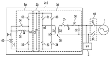
도 2는 도 1에 도시된 배터리 온도 제어 시스템의 실시예에 대한 회로도이다.2 is a circuit diagram of an embodiment of the battery temperature control system shown in FIG.
도 2를 참조하면, 본 발명의 실시예에 의한 배터리 온도 제어 시스템(210)은 도 1에 도시된 전력 저장 시스템의 구성요소들 중 배터리(60), 컨버터(50), DC 링크부(20), 인버터(30)로 구성되며, 도 2에서는 상기 배터리 온도 제어 시스템(210)과 연결되는 부하(2)와, 계통 연계기(40) 및 계통(1)이 도시되어 있다.Referring to FIG. 2, a battery
단, 도 2에서는 배터리(60)만 도시되어 있으나, 이는 설명의 편의를 위한 것으로 상기 배터리(60)에는 BMS가 포함되어 구현될 수 있다.In FIG. 2, only the
상기 컨버터(50)는 도 2에 도시된 바와 같이 제 1, 2스위치(52, 53) 및 하나의 인덕터(L1)(51)로 구성되어 양방향 컨버팅 동작을 수행할 뿐 아니라, 상기 인덕터(51)와 병렬로 연결된 제 3스위치(54)가 추가로 구성됨으로써, 상기 인덕터(51)를 경유하지 않고 곧바로 배터리(60) 측으로의 충방전 전류 패스를 형성함을 특징으로 한다. 2, the
상기 인덕터(51)는 도시된 바와 같이 코일로 구현될 수 있으며, 이는 배터리(60)의 제 1단자(+)에 연결되는 제 1단자와, 상기 제 1스위치(52) 및 제 2스위치(53)의 사이의 노드(n1)와 연결되는 제 2단자를 포함한다. The
상기 제 1스위치(52)는 DC 링크부(20)를 구성하는 캐패시터(C1)의 제 1단자와 인덕터(51)의 제 2단자를 연결한다. 즉, 제 1스위치(52)의 제 1단자는 상기 캐패시터(C1)의 제 1단자와 연결되고, 제 1스위치(52)의 제 2단자는 상기 인덕터(51)의 제 2단자와 연결된다. The
또한, 상기 제 2스위치(53)는 인덕터(51)의 제 2단자와, DC 링크부(20)를 구성하는 캐패시터(C1)의 제 2단자 및 배터리(60)의 제 2단자(-)를 연결한다. 즉, 제 2스위치(53)의 제 1단자는 상기 인덕터(51)의 제 2단자와 연결되고, 제 2스위치(53)의 제 2단자는 상기 캐패시터(C1)의 제 2단자 및 배터리(60)의 제 2단자(-)와 연결된다. The
이와 같은 상기 제 1, 2스위치(52, 53)은 IGBT(Insulated gate bipolar transistor) 또는 MOSFET 스위치로 구현될 수 있으나, 이 외에도 스위칭 기능을 하는 스위칭 소자라면 모두 가능하다. 단, 상기 제 1, 2스위치(52, 53)가 MOSFET 스위치인 경우라면 상기 스위치(52, 53)의 제 1 단자는 소스 단자이고, 제 2 단자는 드레인 단자일 수 있다.The first and
이와 같은 구성을 갖는 컨버터(50)는 입력되는 전력의 전압을 승압하는 승압 컨버터 또는 강압할 수 있는 벅 컨버터로서 작용하는 양방향 컨버팅 동작을 수행할 수 있다.The
또한, 본 발명의 실시예에 의한 컨버터(50)는 기존의 일반적인 양방향 컨버팅 동작을 수행할 뿐 아니라, 상기 인덕터(51)를 경유하지 않고 곧바로 배터리(60) 측으로의 충방전 전류 패스를 형성할 수 있도록 상기 인덕터(51)와 병렬로 연결된 제 3스위치(54)가 추가로 구성됨을 특징으로 한다.In addition, the
즉, 상기 컨버터(50)에는 도시된 바와 같이 상기 배터리(60)의 제 1단자(+)와, 상기 제 1스위치(52) 및 제 2스위치(53)의 사이의 노드(n1)를 연결하는 제 3스위치(54)가 더 포함된다. That is, as shown in the figure, the
따라서, 상기 제 3스위치(54)가 턴 온되면 상기 인덕터(51)를 경유하지 않고 곧바로 배터리(60) 측으로의 충방전 전류 패스가 형성되는 것이다.Therefore, when the
이 때, 상기 제 1 내지 3스위치(52, 53, 54)의 턴 온/오프의 제어는 앞서 도 1에 도시된 제어기(80)에 의해 수행된다.
At this time, the control of turning on / off of the first to
다음으로 상기 인버터(30)는 도 2에 도시된 바와 같이 4개의 스위치들(31 내지 34)로 구성된 풀 브릿지(Full Bridge) 구조이고, 1차측과 2차측이 비접촉 변압기(38)로 구분되는 절연형 풀 브릿지 구조로 구현됨을 특징으로 한다. 2, the
이 때, 상기 비접촉 변압기(38)는 1차측의 제 1권선(l1)과, 2차측의 제 2권선(l2)이 일정한 공극을 유지한 채로 분리된 것으로, 이는 감전 및 접촉 불량의 문제가 발생하지 않는다는 장점이 있다. 상기 제 1 및 제 2권선(l1, l2)는 코일로 구현될 수 있다. At this time, the
상기 인버터(30)는 도 2에 도시된 바와 같이 상기 비접촉 변압기(38)의 1차측에 제 1 내지 4스위치(31 내지 34)들이 구비되고, 상기 비접촉 변압기(38)의 2차측에는 직렬로 연결된 제 5스위치(35) 및 다이오드(D), 인덕터(L2)(36)와, 상기 인덕터(L2)(36)에 병렬로 연결된 캐패시터(C2)가 구비된다.2, the
여기서, 상기 다이오드(D)는 출력측으로 전달되는 전력을 정류하는 역할을 수행하고, 상기 캐패시터(C2)는 2차측에 연결된 부하(2)의 변동에 따른 일정한 출력 특성을 얻기 위해 사용된다.Here, the diode D serves to rectify the electric power delivered to the output side, and the capacitor C2 is used to obtain a constant output characteristic according to the variation of the
본 발명의 실시예에 의한 인버터(30)는 상기 1차측에 구비된 제 1 내지 4스위치들(31 내지 34)과 2차측에 구비된 인덕터(L2)를 통해 양방향 인버팅 동작을 수행할 뿐 아니라, 상기 비접촉 변압기(38)의 2차측에 직렬로 구비되어 상기 2차측의 연결을 제어하는 제 5스위치(37)가 추가로 구성됨을 특징으로 한다.The
즉, 상기 제 5스위치(37)가 턴 온된 경우 상기 인버터(30)는 일반적인 양방향 인버팅 동작을 수행하고, 상기 제 5스위치(35)가 턴 오프되면 상기 1차측의 제 1권선(l1)이 무효 전력을 생성하는 인덕터의 역할을 수행하여 상기 발생된 무효전력에 의한 충방전 전류를 배터리측에 제공하는 역할을 수행하게 된다.
That is, when the fifth switch 37 is turned on, the
보다 구체적으로 상기 인덕터(30)의 1차측에 구비된 풀 브릿지 구조의 스위치들 중 상기 제 1스위치(31)는 DC 링크부(20)를 구성하는 캐패시터(C1)의 제 1단자와 제 1권선(l1)의 제 1단자를 연결한다. 즉, 제 1스위치(31)의 제 1단자는 상기 캐패시터(C1)의 제 1단자와 연결되고, 제 1스위치(31)의 제 2단자는 상기 제 1권선(l1)의 제 1단자와 연결된다.
More specifically, among the switches of the full bridge structure provided on the primary side of the
상기 제 2스위치(32)는 제 1권선(l1)의 제 1단자와, DC 링크부(20)를 구성하는 캐패시터(C1)의 제 2단자 및 배터리(60)의 제 2단자(-)를 연결한다. 즉, 제 2스위치(32)의 제 1단자는 상기 제 1권선(l1)의 제 1단자와 연결되고, 제 2스위치(32)의 제 2단자는 상기 캐패시터(C1)의 제 2단자 및 배터리(60)의 제 2단자(-)와 연결된다. The
또한, 상기 풀 브릿지 구조의 스위치들 중 상기 제 3스위치(33)는 DC 링크부(20)를 구성하는 캐패시터(C1)의 제 1단자와 제 1권선(l1)의 제 2단자를 연결한다. 즉, 제 3스위치(33)의 제 1단자는 상기 캐패시터(C1)의 제 1단자와 연결되고, 제 3스위치(33)의 제 2단자는 상기 제 1권선(l1)의 제 2단자와 연결된다. The
상기 제 4스위치(34)는 제 1권선(l1)의 제 2단자와, DC 링크부(20)를 구성하는 캐패시터(C1)의 제 2단자 및 배터리(60)의 제 2단자(-)를 연결한다. 즉, 제 4스위치(34)의 제 1단자는 상기 제 1권선(l1)의 제 2단자와 연결되고, 제 4스위치(34)의 제 2단자는 상기 캐패시터(C1)의 제 2단자 및 배터리(60)의 제 2단자(-)와 연결된다. The
이와 같은 상기 제 1 내지 4스위치(31 내지 34)은 IGBT(Insulated gate bipolar transistor) 또는 MOSFET 스위치로 구현될 수 있으나, 이 외에도 스위칭 기능을 하는 스위칭 소자라면 모두 가능하다. 단, 상기 제 1 내지 4스위치(31 내지 34)가 MOSFET 스위치인 경우라면 상기 스위치들의 제 1 단자는 소스 단자이고, 제 2 단자는 드레인 단자일 수 있다.The first to
이와 같은 구성을 갖는 인버터(50)는 직류 전압을 교류 전압으로 변환하거나, 교류 전압을 정류하여 직류 전압을 변환하는 양방향 인버팅 동작을 수행할 수 있다.The
또한, 본 발명의 실시예에 의한 인버터(30)는 기존의 일반적인 양방향 인버팅 동작을 수행할 뿐 아니라, 상기 제 1권선(l1)을 이용하여 배터리 측으로 전달되는 충방전 전류를 발생시키기 위해 상기 2차측의 연결을 끊는 제 5스위치(35)가 추가로 구성됨을 특징으로 한다.In addition, the
즉, 도 2에 도시된 실시예의 경우 상기 제 5스위치(35)는 상기 비접촉 변압기(38) 2차측을 구성하는 제 2권선(l2)의 제 1단자와 상기 다이오드(D)의 애노드 전극을 연결하도록 구성된다. 2, the
따라서, 상기 제 5스위치(37)가 턴 오프되면 상기 비접촉 변압기(38)의 2차측 연결이 끊어지게 되고, 이에 상기 비접촉 변압기(38)의 1차측에 구비된 제 1권선(L1)에서 전류가 부하(2) 또는 계통(1)이 아닌 배터리(60) 측으로의 전달될 수 있게 된다. Therefore, when the fifth switch 37 is turned off, the secondary side connection of the
단, 이 경우 상기 계통 연계기(40)에 구비된 스위치들(41, 42)이 모두 턴 오프되어 상기 인버터(50)에 의해 변환된 전압이 상기 부하(2) 또는 계통(1)으로 전달되지 않도록 추가로 제어됨이 바람직하다.In this case, all the
이 때, 상기 인버터(30)의 제 1 내지 5스위치(31, 32, 33, 34, 37) 및 계통 연계기(40)에 구비된 스위치들에 대한 턴 온/오프의 제어는 앞서 도 1에 도시된 제어기(80)에 의해 수행된다.
At this time, the control of the turn-on / off of the switches provided in the first to
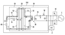
도 3a 내지 도 3c는 도 2에 도시된 배터리 온도 제어 시스템의 동작을 설명하는 도면이다.FIGS. 3A to 3C are views for explaining the operation of the battery temperature control system shown in FIG. 2. FIG.
단, 도 2 및 3을 통해 설명하는 배터리 온도 제어 시스템의 동작은, 상기 전력 저장 시스템(100)의 동작 중 배터리(60)의 저온 상태가 일정기간 유지됨이 제어기(80)에 의해 감지된 경우에 대응되는 동작이다.The operation of the battery temperature control system described with reference to FIGS. 2 and 3 may be modified such that when the low temperature state of the
즉, 제어기(80)는 배터리(60)와 연결된 BMS를 통해 주기적으로 배터리의 정보를 수신하므로, 배터리(60)가 소정 기간 저온 상태가 유지되는 것을 감지할 수 있다. That is, the
상기 제어기(80)에 의해 배터리(60)의 저온 상태가 감지되면, 이후 상기 제어기(80)는 상기 배터리(60)의 온도를 상승시키기 위해 도 2에 도시된 배터리 온도 제어 시스템(200)의 동작을 제어하며, 이 경우 상기 전력 저장 시스템(100)의 기본적인 동작은 상기 배터리(60)가 정상 온도를 회복할 때까지 보류된다.When the low temperature state of the
상기 배터리 온도를 제어하는 기간 동안 상기 제어기(80)는 계통(1) 및 부하(2)와의 연결을 끊고 전력 저장 시스템(100)의 인버터(30)에 구비된 상기 비접촉 변압기(38)의 제 1권선(l1)을 이용하여 상기 배터리(60) 측에 충방전 전류를 발생시킴을 통해 배터리의 온도를 상승시키는 동작을 수행하게 되며, 이하 도 3a 내지 도 3c를 통해 이를 보다 구체적으로 설명하도록 한다.The
먼저 도 1 및 도 3a를 참조하면, 제어기(80)가 배터리(60)에 구비된 BMS를 통해 배터리(60)의 저온 상태를 감지하면, 상기 제어기(80)는 인버터의 제 5스위치(35) 및 계통 연계기(40)의 스위치들(41, 42)을 턴 오프하여, 상기 전력 저장 시스템(100)과 상기 부하(3) 및 계통(1)과의 연계를 차단한다.1 and 3A, when the
또한, 컨버터(50)에 포함된 제 3스위치(54) 및 DC 링크부에 구비된 캐패시터(C1)의 제 1단자와 연결된 제 1스위치(52)를 턴 온하여 상기 배터리(60)가 컨버터(50)의 인덕터(51)를 경유하지 않고 상기 인버터(30)와 직접 연결될 수 있도록 전류 패스가 형성된다. The
이후 상기 인버터(30)에 구비된 풀 브릿지 구조로 구현되는 4개의 스위치들을 2개씩 교변 동작하여 상기 배터리의 충 방전 동작을 반복 수행하도록 한다.Thereafter, the four switches implemented in the full bridge structure of the
즉, 도 3b를 참조하면, 이는 상기 제어기(80)가 상기 인버터(30)에 포함된 스위치들 중 제 1 및 제 4스위치(31, 34)를 턴 온하고, 제 2 및 제 3스위치(32, 33)를 턴 오프한 것을 나타낸다.3B, this means that the
이 경우 도시된 바와 같이 상기 배터리(60)는 상기 배터리(60)의 제 1단자(+)에서부터 컨버터(50)의 제 3스위치(54) 및 제 1스위치(52)와, DC 링크부(20)에 구비된 캐패시터(C1)의 제 1단자와, 인버터(30)의 제 1스위치(31)와, 인버터(30)의 제 1권선(l1) 및 인버터(30)의 제 4스위치(34)를 거쳐 배터리(60)의 제 2단자(-)까지의 방전 패스가 형성된다. The
즉, 상기 도 3b에 의할 경우 상기 배터리(60)에는 상기 방전 패스를 통해 방전 전류가 흐르게 된다. That is, in the case of FIG. 3B, a discharge current flows through the discharge path to the
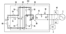
또한, 도 3c를 참조하면, 이는 상기 제어기(80)가 상기 인버터(30)에 포함된 스위치들 중 제 2 및 제 3스위치(32, 33)를 턴 온하고, 제 1 및 제 4스위치(31, 34)를 턴 오프한 것을 나타낸다.3C, when the
이 경우 상기 도 3b의 방전 패스와 반대의 방향을 갖는 충전 패스가 형성되고, 이를 통해 상기 인버터(30)의 제 1권선(l1)에 저장된 무효전력이 상기 배터리로 전달되어 상기 배터리(60)가 충전될 수 있게 된다.In this case, a charging path having a direction opposite to that of the discharging path of FIG. 3B is formed, whereby reactive power stored in the first winding 11 of the
즉, 상기 도 3c에 의할 경우 상기 배터리(60)에는 상기 충전 패스를 통해 충전 전류가 흐르게 된다. In other words, in the case of FIG. 3C, the charging current flows in the
상기 충전 패스는 도 3c에 도시된 바와 같이 배터리(60)의 제 2단자(-)에서부터 DC 링크부(20)에 구비된 캐패시터(C1)의 제 2단자와, 인버터(30)의 제 2스위치(32) 및 제 1권선(l1)과, 인버터의 제 3스위치(33) 및 DC 링크부(20)에 구비된 캐패시터(C1)의 제1단자와, 컨버터(50)의 제 1스위치(52) 및 제 3스위치(54)를 거쳐 배터리(60)의 제 1단자(+)까지의 경로가 된다.3C, the charging path includes a second terminal of the capacitor C1 provided in the
상기 제어기(80)는 도 3b 및 도 3c의 동작을 반복하여 수행함을 통해 배터리(60)에는 충전 및 방전전류가 반복하여 흐르게 되고, 이 전류로 인해 배터리(60)의 온도는 상승하게 된다.The
이후 배터리(60)의 온도가 정상 온도 범위에 도달하면, 상기 제어기(80)는 본 발명의 실시예에 의한 배터리 온도 제어 시스템의 동작을 종료하고, 전력 저장 시스템(100)의 기본적인 동작을 수행한다.Thereafter, when the temperature of the
즉, 상기 인버터(30)의 2차측에 구비된 제 5스위치(35)을 턴 온하여 인버터(30)가 기본적인 양방향 인버팅 동작을 수행하고, 계통 연계기(40)의 스위치들(41, 42)을 턴 온하여 상기 전력 저장 시스템(100)을 상기 부하(3) 및 계통(1)과 연결시킨다. That is, the
이와 마찬가지로 상기 컨버터(50)에 포함된 제 3스위치(54)를 턴 오프하여 컨버터(50)가 기본적인 양방향 컨버팅 동작만을 수행한다. 즉, 상기 배터리 온도 제어 시스템 동작 시 형성된 충방전 전류 패스가 차단된다.
Likewise, the
이상 설명한 내용을 통해 당업자라면 본 발명의 기술사상을 일탈하지 아니하는 범위에서 다양한 변경 및 수정이 가능함을 알 수 있을 것이다. 따라서, 본 발명의 기술적 범위는 명세서의 상세한 설명에 기재된 내용으로 한정되는 것이 아니라 특허 청구의 범위에 의하여 정하여져야만 한다.It will be apparent to those skilled in the art that various modifications and variations can be made in the present invention without departing from the spirit or scope of the invention. Therefore, the technical scope of the present invention should not be limited to the contents described in the detailed description of the specification, but should be determined by the claims.
100: 전력 저장 시스템 20: DC 링크부
30: 인버터 50: 컨버터
60: 배터리 80: 제어기
200: 배터리 온도 제어 시스템100: power storage system 20: DC link part
30: inverter 50: converter
60: Battery 80: Controller
200: Battery temperature control system
Claims (11)
복수의 스위치 및 하나의 인덕터로 구성되어 상기 배터리의 전압을 승압 또는 감압하는 컨버터와;
상기 컨버터의 출력 전압을 안정화시키는 캐패시터가 구비된 DC 링크부와;
1차측의 제 1권선 및 2차측의 제 2권선이 공극을 유지하여 분리된 비접촉 변압기와, 상기 1차측에 구비된 제 1 내지 제 4스위치와, 상기 2차측에 구비된 제 5스위치 및 인덕터를 포함하여 구성되는 인버터가 포함됨을 특징으로 하는 배터리 온도 제어 시스템.A battery included in the power storage system;
A converter configured to include a plurality of switches and one inductor to step up or down a voltage of the battery;
A DC link unit having a capacitor for stabilizing the output voltage of the converter;
A non-contact transformer in which a first winding of a primary side and a second winding of a secondary side are separated by keeping a gap, first to fourth switches provided on the primary side, and a fifth switch and an inductor And an inverter configured to control the temperature of the battery.
상기 컨버터는,
상기 배터리의 제 1단자에 연결되는 인덕터와;
상기 DC 링크부에 구비된 캐패시터의 제 1단자와 상기 인덕터의 제 2단자 사이에 연결되는 제 1스위치와;
상기 인덕터의 제 2단자와 상기 배터리의 제 2단자 사이에 연결되는 제 2스위치가 포함됨을 특징으로 하는 배터리 온도 제어 시스템.The method according to claim 1,
The converter includes:
An inductor connected to a first terminal of the battery;
A first switch connected between a first terminal of the capacitor included in the DC link unit and a second terminal of the inductor;
And a second switch connected between a second terminal of the inductor and a second terminal of the battery.
상기 인덕터와 병렬로 연결된 제 3스위치가 더 포함됨을 특징으로 하는 배터리 온도 제어 시스템. 3. The method of claim 2,
And a third switch connected in parallel with the inductor.
상기 1차측에 구비된 제 1 내지 제 4스위치들은 풀 브릿지(Full Bridge) 구조로 구현됨을 특징으로 하는 배터리 온도 제어 시스템.The method according to claim 1,
Wherein the first to fourth switches provided on the primary side are implemented as a full bridge structure.
상기 풀브릿지 구조의 스위치들은,
상기 DC 링크부에 구비된 캐패시터의 제 1단자와 상기 비접촉 변압기의 1차측 제 1권선의 제 1단자 사이에 연결되는 제 1스위치와;
상기 제 1권선의 제 1단자와 상기 배터리의 제 2단자 사이에 연결되는 제 2스위치와;
상기 DC 링크부에 구비된 캐패시터의 제 1단자와 상기 제 1권선의 제 2단자 사이에 연결되는 제 3스위치와;
상기 제 1권선의 제 2단자와 상기 배터리의 제 2단자 사이에 연결되는 제 4스위치로 구성됨을 특징으로 하는 배터리 온도 제어 시스템.5. The method of claim 4,
The switches of the full-
A first switch connected between a first terminal of a capacitor provided in the DC link part and a first terminal of a first primary winding of the noncontact transformer;
A second switch connected between a first terminal of the first winding and a second terminal of the battery;
A third switch connected between a first terminal of the capacitor included in the DC link unit and a second terminal of the first winding;
And a fourth switch connected between a second terminal of the first winding and a second terminal of the battery.
상기 비접촉 변압기의 2차측에 구비된 제 5스위치 및 인덕터는 직렬로 연결됨을 특징으로 하는 배터리 온도 제어 시스템.The method according to claim 1,
And the fifth switch and the inductor connected to the secondary side of the non-contact transformer are connected in series.
상기 제 5스위치와 인덕터 사이에 다이오드가 추가로 더 구비됨을 특징으로 하는 배터리 온도 제어 시스템.The method according to claim 6,
And a diode is additionally provided between the fifth switch and the inductor.
상기 다이오드는 애노드 전극이 상기 제 5스위치의 제 2단자와 접속되도록 직렬로 연결됨을 특징으로 하는 배터리 온도 제어 시스템. 8. The method of claim 7,
Wherein the diode is connected in series so that the anode electrode is connected to the second terminal of the fifth switch.
상기 배터리의 저온 상태가 일정기간 유지됨이 감지되는 단계와;
상기 배터리의 저온 상태가 감지되면, 상기 전력 저장 시스템 내의 인버터에 구비된 비접촉 변압기의 2차측 연결이 차단되는 단계와;
상기 비접촉 변압기의 1차측 제 1권선에서 생성된 전류가 상기 배터리 측으로 전달되는 충방전 전류 패스가 형성되는 단계와;
상기 비접촉 변압기의 1차측에 구비된 복수개의 스위치들이 한 쌍씩 교변 동작하여 상기 충방전 전류 패스를 통해 상기 배터리의 충 방전 동작이 반복 수행되는 단계가 포함됨을 특징으로 하는 배터리 온도 제어 방법.A method for controlling a temperature of a battery included in a power storage system,
Detecting that the low temperature state of the battery is maintained for a predetermined period;
Detecting a low temperature state of the battery, disconnecting the secondary side connection of the non-contact transformer provided in the inverter in the power storage system;
Forming a charge / discharge current path through which a current generated in the primary winding of the non-contact transformer is transferred to the battery;
Wherein a plurality of switches provided on a primary side of the noncontact transformer are interchangeably operated by a pair so that charging and discharging operations of the battery are repeatedly performed through the charging and discharging current path.
상기 비접촉 변압기의 2차측 연결이 차단될 때, 상기 전력 저장 시스템과 연계된 계통 및 부하의 연결이 차단되는 단계가 더 포함됨을 특징으로 하는 배터리 온도 제어 방법.10. The method of claim 9,
Further comprising disconnecting a system and a load connected to the power storage system when the secondary side connection of the non-contact transformer is cut off.
상기 배터리의 온도가 정상 온도 범위에 도달한 이후 상기 전력 저장 시스템이 상기 부하 및 계통과 연결되고 상기 형성된 충방전 전류 패스가 차단되는 단계가 더 포함됨을 특징으로 하는 배터리 온도 제어 방법.10. The method of claim 9,
Further comprising: after the temperature of the battery reaches a normal temperature range, the power storage system is connected to the load and the system and the formed charge / discharge current path is blocked.
Priority Applications (5)
| Application Number | Priority Date | Filing Date | Title |
|---|---|---|---|
| KR1020130009090A KR20140097628A (en) | 2013-01-28 | 2013-01-28 | temperature controlling system of battery and controlling method thereof |
| US13/924,383 US9153976B2 (en) | 2013-01-28 | 2013-06-21 | System and method of battery temperature control |
| JP2013133457A JP2014146589A (en) | 2013-01-28 | 2013-06-26 | Battery temperature control system, and method of controlling the same |
| EP13182634.9A EP2760100A2 (en) | 2013-01-28 | 2013-09-02 | Temperature Controlling System and Method of Battery |
| CN201310470310.5A CN103972605A (en) | 2013-01-28 | 2013-10-10 | Temperature Controlling System and Method of Battery |
Applications Claiming Priority (1)
| Application Number | Priority Date | Filing Date | Title |
|---|---|---|---|
| KR1020130009090A KR20140097628A (en) | 2013-01-28 | 2013-01-28 | temperature controlling system of battery and controlling method thereof |
Publications (1)
| Publication Number | Publication Date |
|---|---|
| KR20140097628A true KR20140097628A (en) | 2014-08-07 |
Family
ID=49080790
Family Applications (1)
| Application Number | Title | Priority Date | Filing Date |
|---|---|---|---|
| KR1020130009090A KR20140097628A (en) | 2013-01-28 | 2013-01-28 | temperature controlling system of battery and controlling method thereof |
Country Status (5)
| Country | Link |
|---|---|
| US (1) | US9153976B2 (en) |
| EP (1) | EP2760100A2 (en) |
| JP (1) | JP2014146589A (en) |
| KR (1) | KR20140097628A (en) |
| CN (1) | CN103972605A (en) |
Cited By (3)
| Publication number | Priority date | Publication date | Assignee | Title |
|---|---|---|---|---|
| US11186197B2 (en) | 2016-10-05 | 2021-11-30 | Samsung Electronics Co., Ltd. | Method of controlling temperature of battery, and battery management apparatus and system |
| CN114616117A (en) * | 2019-10-30 | 2022-06-10 | 株式会社电装 | Power conversion device |
| KR20220119810A (en) | 2021-02-22 | 2022-08-30 | 주식회사 인투아이피 | System control device that measurement and manages the temperature of the storage battery in real time |
Families Citing this family (20)
| Publication number | Priority date | Publication date | Assignee | Title |
|---|---|---|---|---|
| KR101698771B1 (en) * | 2013-01-16 | 2017-01-23 | 삼성에스디아이 주식회사 | temperature controlling system of battery and controlling method thereof |
| US20160134147A1 (en) * | 2013-06-13 | 2016-05-12 | Firebright1 Green Energy(Shanghai) Limited. | Battery Energy Storage System and Controlling Method |
| US20160111904A1 (en) * | 2014-10-16 | 2016-04-21 | Aurosens Inc. | Multi-function Apparatus |
| KR102092159B1 (en) | 2015-02-25 | 2020-03-24 | 엘에스산전 주식회사 | Method for controlling trip of inverter |
| CN106553559B (en) * | 2015-09-29 | 2019-03-29 | 比亚迪股份有限公司 | Electric car and its heating system |
| CN105896744A (en) * | 2016-04-26 | 2016-08-24 | 圣邦微电子(北京)股份有限公司 | LC tank circuit resonant coupling and non-resonant coupling tank circuit control method and circuit |
| JP6596383B2 (en) * | 2016-05-23 | 2019-10-23 | 本田技研工業株式会社 | Charge / discharge device, transport equipment, and control method |
| CN109428388A (en) * | 2017-09-01 | 2019-03-05 | 硕天科技股份有限公司 | Uninterrupted power supply system |
| WO2019145997A1 (en) * | 2018-01-23 | 2019-08-01 | Tdk株式会社 | Dc feeding system |
| KR102394826B1 (en) * | 2018-02-14 | 2022-05-04 | 주식회사 엘지에너지솔루션 | Power supply circuit for energy transfer between battery and smoothing capacitor and battery management system including the same |
| DE102018208330A1 (en) * | 2018-05-26 | 2019-11-28 | Robert Bosch Gmbh | Method for heating a battery module |
| JP7370223B2 (en) * | 2019-01-24 | 2023-10-27 | 株式会社Soken | power converter |
| CN110970965B (en) * | 2019-06-24 | 2020-11-06 | 宁德时代新能源科技股份有限公司 | Switch control device and method, motor controller and battery pack heating control system |
| CN110803069B (en) * | 2019-10-22 | 2021-04-02 | 上海交通大学 | Control method of battery double-circuit power supply resonant alternating current heating system |
| JP7075385B2 (en) * | 2019-10-30 | 2022-05-25 | 株式会社Soken | Power converter |
| CN111660875B (en) * | 2020-06-04 | 2021-04-20 | 比亚迪股份有限公司 | Vehicle, energy conversion device, and control method therefor |
| CN112234696B (en) * | 2020-09-30 | 2022-09-06 | 普联技术有限公司 | Control method and device for lithium battery auxiliary heating system |
| KR102565431B1 (en) * | 2020-12-31 | 2023-08-11 | 주식회사 큐아이티 | Switching operation method and an inverter device for grid connection considering transformer magnetization |
| CN114336995A (en) * | 2021-04-30 | 2022-04-12 | 华为数字能源技术有限公司 | Receiving end, transmitting end and wireless charging system of wireless charging system |
| CN115668588A (en) * | 2022-03-11 | 2023-01-31 | 宁德时代新能源科技股份有限公司 | Battery heating device, control method and circuit thereof, and power device |
Family Cites Families (26)
| Publication number | Priority date | Publication date | Assignee | Title |
|---|---|---|---|---|
| US4688160A (en) * | 1985-12-19 | 1987-08-18 | American Telephone And Telegraph Co., At&T Bell Labs | Single ended forward converter with resonant commutation of magnetizing current |
| DE4236286A1 (en) * | 1992-10-28 | 1994-05-05 | Daimler Benz Ag | Method and arrangement for automatic contactless charging |
| CN1077341C (en) * | 1995-08-10 | 2002-01-02 | 索尼公司 | Charging method, charging device and integrated circuit |
| DE19904181A1 (en) | 1999-02-03 | 2000-08-10 | Nokia Mobile Phones Ltd | Device for reactivating an electric battery |
| US6340879B1 (en) | 1999-02-03 | 2002-01-22 | Nokia Mobile Phones Ltd. | Device for reactivating an electric battery |
| US6650552B2 (en) * | 2001-05-25 | 2003-11-18 | Tdk Corporation | Switching power supply unit with series connected converter circuits |
| US20050253557A1 (en) * | 2004-05-14 | 2005-11-17 | Grand Power Sources Inc. | Electric charging system |
| JP4222355B2 (en) * | 2005-09-29 | 2009-02-12 | トヨタ自動車株式会社 | PARKING ASSISTANCE DEVICE AND POWER TRANSFER METHOD BETWEEN VEHICLE AND GROUND EQUIPMENT |
| US8575897B2 (en) * | 2008-10-03 | 2013-11-05 | Denso Corporation | Battery temperature control system |
| JP5035427B2 (en) * | 2008-11-28 | 2012-09-26 | トヨタ自動車株式会社 | Vehicle charging system |
| US8069100B2 (en) * | 2009-01-06 | 2011-11-29 | Access Business Group International Llc | Metered delivery of wireless power |
| DE102009000328A1 (en) * | 2009-01-20 | 2010-07-22 | Semikron Elektronik Gmbh & Co. Kg | Battery charger and method of operation |
| US8350538B2 (en) * | 2009-04-11 | 2013-01-08 | Cuks, Llc | Voltage step-down switching DC-to-DC converter |
| US8350523B2 (en) * | 2009-08-05 | 2013-01-08 | GM Global Technology Operations LLC | Charging system with galvanic isolation and multiple operating modes |
| US8374004B2 (en) * | 2009-08-14 | 2013-02-12 | Marvell World Trade Ltd. | Isolated AC-DC converter with master controller on secondary side and slave controller on primary side |
| KR101084214B1 (en) * | 2009-12-03 | 2011-11-18 | 삼성에스디아이 주식회사 | Grid-connected energy storage system and method for controlling grid-connected energy storage system |
| KR101166020B1 (en) | 2010-05-31 | 2012-07-19 | 삼성에스디아이 주식회사 | A contactless power charging system and energy storage system including the contactless charging system |
| KR101116428B1 (en) | 2010-07-14 | 2012-03-05 | 삼성에스디아이 주식회사 | Energy Storage System |
| JP2012070502A (en) * | 2010-09-22 | 2012-04-05 | Toyota Motor Corp | Power control unit to be mounted on vehicle |
| KR101194485B1 (en) * | 2010-10-19 | 2012-10-24 | 삼성전기주식회사 | Charging equipment of Variable frequency control for power factor |
| US9266441B2 (en) * | 2011-01-19 | 2016-02-23 | Technova Inc. | Contactless power transfer system |
| TW201251289A (en) * | 2011-06-07 | 2012-12-16 | Delta Electronics Inc | Integrated buck/boost converter of charging apparatus |
| JP6088234B2 (en) * | 2011-12-23 | 2017-03-01 | 株式会社半導体エネルギー研究所 | Power receiving device, wireless power feeding system |
| WO2013097801A1 (en) * | 2011-12-31 | 2013-07-04 | 深圳市比亚迪汽车研发有限公司 | Electric automobile and integrated control system thereof |
| CN202455130U (en) * | 2011-12-31 | 2012-09-26 | 比亚迪股份有限公司 | Charging/discharging control system of electric vehicle and electric vehicle |
| TWI514733B (en) * | 2012-07-25 | 2015-12-21 | Phihong Technology Co Ltd | Non-contact transformer system |
-
2013
- 2013-01-28 KR KR1020130009090A patent/KR20140097628A/en not_active Application Discontinuation
- 2013-06-21 US US13/924,383 patent/US9153976B2/en active Active
- 2013-06-26 JP JP2013133457A patent/JP2014146589A/en active Pending
- 2013-09-02 EP EP13182634.9A patent/EP2760100A2/en not_active Withdrawn
- 2013-10-10 CN CN201310470310.5A patent/CN103972605A/en active Pending
Cited By (4)
| Publication number | Priority date | Publication date | Assignee | Title |
|---|---|---|---|---|
| US11186197B2 (en) | 2016-10-05 | 2021-11-30 | Samsung Electronics Co., Ltd. | Method of controlling temperature of battery, and battery management apparatus and system |
| CN114616117A (en) * | 2019-10-30 | 2022-06-10 | 株式会社电装 | Power conversion device |
| CN114616117B (en) * | 2019-10-30 | 2024-02-23 | 株式会社电装 | Power conversion device |
| KR20220119810A (en) | 2021-02-22 | 2022-08-30 | 주식회사 인투아이피 | System control device that measurement and manages the temperature of the storage battery in real time |
Also Published As
| Publication number | Publication date |
|---|---|
| US20140210417A1 (en) | 2014-07-31 |
| JP2014146589A (en) | 2014-08-14 |
| CN103972605A (en) | 2014-08-06 |
| EP2760100A2 (en) | 2014-07-30 |
| US9153976B2 (en) | 2015-10-06 |
Similar Documents
| Publication | Publication Date | Title |
|---|---|---|
| KR101678536B1 (en) | temperature controlling system of battery and energy storage system using the same and controlling method thereof | |
| KR101698771B1 (en) | temperature controlling system of battery and controlling method thereof | |
| KR20140097628A (en) | temperature controlling system of battery and controlling method thereof | |
| KR101146670B1 (en) | Energy management system and method for controlling thereof | |
| US8552590B2 (en) | Energy management system and grid-connected energy storage system including the energy management system | |
| US9293923B2 (en) | Energy storage system and controlling method of the same | |
| KR101369692B1 (en) | Energy storage system and controlling method of the same | |
| KR101174891B1 (en) | Energy storage system and controlling method of the same | |
| KR101193168B1 (en) | Power storage system, controlling method of the same, and recording medium storing program to execute the method | |
| US20110148360A1 (en) | Energy storage system and method of controlling the same | |
| JP2011109901A5 (en) | ||
| KR20110068639A (en) | Energy storage system and method for controlling thereof | |
| KR20110133809A (en) | Energy storage system | |
| KR20110062392A (en) | Grid-connected energy storage system and method for controlling grid-connected energy storage system | |
| KR20140115501A (en) | Power conversion device having battery heating function | |
| KR101688485B1 (en) | Energy storage apparatus | |
| KR101106413B1 (en) | Inverter of energy storage system | |
| KR20140115502A (en) | Power conversion device having battery heating function | |
| KR20140058770A (en) | Method and system for operation mode decision of power management system | |
| US20140085935A1 (en) | Power conversion device |
Legal Events
| Date | Code | Title | Description |
|---|---|---|---|
| A201 | Request for examination | ||
| E902 | Notification of reason for refusal | ||
| E601 | Decision to refuse application |