EP2802027A1 - Ensemble d'électrodes comprenant une électrode positive et une électrode négative de formes différentes, et batterie rechargeable - Google Patents
Ensemble d'électrodes comprenant une électrode positive et une électrode négative de formes différentes, et batterie rechargeable Download PDFInfo
- Publication number
- EP2802027A1 EP2802027A1 EP13777711.6A EP13777711A EP2802027A1 EP 2802027 A1 EP2802027 A1 EP 2802027A1 EP 13777711 A EP13777711 A EP 13777711A EP 2802027 A1 EP2802027 A1 EP 2802027A1
- Authority
- EP
- European Patent Office
- Prior art keywords
- tabs
- cathode
- anode
- electrode assembly
- assembly according
- Prior art date
- Legal status (The legal status is an assumption and is not a legal conclusion. Google has not performed a legal analysis and makes no representation as to the accuracy of the status listed.)
- Granted
Links
- -1 or the like Inorganic materials 0.000 claims description 27
- PXHVJJICTQNCMI-UHFFFAOYSA-N nickel Substances [Ni] PXHVJJICTQNCMI-UHFFFAOYSA-N 0.000 claims description 18
- 239000006183 anode active material Substances 0.000 claims description 14
- 238000003466 welding Methods 0.000 claims description 14
- 238000004519 manufacturing process Methods 0.000 claims description 13
- 239000010936 titanium Substances 0.000 claims description 13
- 239000006182 cathode active material Substances 0.000 claims description 12
- 229910052719 titanium Inorganic materials 0.000 claims description 12
- 229910052759 nickel Inorganic materials 0.000 claims description 11
- 239000002131 composite material Substances 0.000 claims description 10
- 229910052742 iron Inorganic materials 0.000 claims description 10
- 229910052782 aluminium Inorganic materials 0.000 claims description 9
- XEEYBQQBJWHFJM-UHFFFAOYSA-N iron Substances [Fe] XEEYBQQBJWHFJM-UHFFFAOYSA-N 0.000 claims description 8
- 239000011572 manganese Substances 0.000 claims description 8
- KLARSDUHONHPRF-UHFFFAOYSA-N [Li].[Mn] Chemical compound [Li].[Mn] KLARSDUHONHPRF-UHFFFAOYSA-N 0.000 claims description 7
- 229910052804 chromium Inorganic materials 0.000 claims description 7
- 229910052725 zinc Inorganic materials 0.000 claims description 7
- 229910052802 copper Inorganic materials 0.000 claims description 6
- 239000010949 copper Substances 0.000 claims description 6
- 239000000463 material Substances 0.000 claims description 6
- 229910052720 vanadium Inorganic materials 0.000 claims description 6
- 239000011701 zinc Substances 0.000 claims description 6
- FDLZQPXZHIFURF-UHFFFAOYSA-N [O-2].[Ti+4].[Li+] Chemical compound [O-2].[Ti+4].[Li+] FDLZQPXZHIFURF-UHFFFAOYSA-N 0.000 claims description 5
- 229910052749 magnesium Inorganic materials 0.000 claims description 5
- 229910052717 sulfur Inorganic materials 0.000 claims description 5
- 229910052723 transition metal Inorganic materials 0.000 claims description 5
- 150000003624 transition metals Chemical class 0.000 claims description 5
- 229910052796 boron Inorganic materials 0.000 claims description 4
- 229910052801 chlorine Inorganic materials 0.000 claims description 4
- 239000011651 chromium Substances 0.000 claims description 4
- 229910052740 iodine Inorganic materials 0.000 claims description 4
- 229910052748 manganese Inorganic materials 0.000 claims description 4
- 229910009109 Li1.33Ti1.67O4 Inorganic materials 0.000 claims description 3
- 229910012616 LiTi2O4 Inorganic materials 0.000 claims description 3
- 229910002097 Lithium manganese(III,IV) oxide Inorganic materials 0.000 claims description 3
- ZYXUQEDFWHDILZ-UHFFFAOYSA-N [Ni].[Mn].[Li] Chemical compound [Ni].[Mn].[Li] ZYXUQEDFWHDILZ-UHFFFAOYSA-N 0.000 claims description 3
- 229910012409 LiNi0.4Mn1.6O4 Inorganic materials 0.000 claims description 2
- 229910002099 LiNi0.5Mn1.5O4 Inorganic materials 0.000 claims description 2
- 229910011328 LiNi0.6Co0.2Mn0.2O2 Inorganic materials 0.000 claims description 2
- 229910015872 LiNi0.8Co0.1Mn0.1O2 Inorganic materials 0.000 claims description 2
- 229910014422 LiNi1/3Mn1/3Co1/3O2 Inorganic materials 0.000 claims description 2
- 229910015043 LiaTibO4 Inorganic materials 0.000 claims description 2
- 229910016093 LixMyMn2-yO4-z Inorganic materials 0.000 claims description 2
- 229910016090 LixMyMn2−yO4-z Inorganic materials 0.000 claims description 2
- 229910015813 LixMyMn2−yO4−z Inorganic materials 0.000 claims description 2
- 229910014516 LixNiyMn2-yO4 Inorganic materials 0.000 claims description 2
- 229910014534 LixNiyMn2−yO4 Inorganic materials 0.000 claims description 2
- 150000001450 anions Chemical class 0.000 claims description 2
- 229910052787 antimony Inorganic materials 0.000 claims description 2
- 229910052797 bismuth Inorganic materials 0.000 claims description 2
- 229910052791 calcium Inorganic materials 0.000 claims description 2
- 229910052758 niobium Inorganic materials 0.000 claims description 2
- 229910052721 tungsten Inorganic materials 0.000 claims description 2
- 229910052726 zirconium Inorganic materials 0.000 claims description 2
- OKTJSMMVPCPJKN-UHFFFAOYSA-N Carbon Chemical compound [C] OKTJSMMVPCPJKN-UHFFFAOYSA-N 0.000 description 13
- 229910052744 lithium Inorganic materials 0.000 description 13
- WHXSMMKQMYFTQS-UHFFFAOYSA-N Lithium Chemical compound [Li] WHXSMMKQMYFTQS-UHFFFAOYSA-N 0.000 description 12
- 239000003792 electrolyte Substances 0.000 description 9
- 229910003002 lithium salt Inorganic materials 0.000 description 7
- 159000000002 lithium salts Chemical class 0.000 description 7
- 239000007784 solid electrolyte Substances 0.000 description 7
- 238000000429 assembly Methods 0.000 description 6
- 230000000712 assembly Effects 0.000 description 6
- 229910052799 carbon Inorganic materials 0.000 description 6
- 239000003575 carbonaceous material Substances 0.000 description 6
- 239000004020 conductor Substances 0.000 description 6
- 239000000945 filler Substances 0.000 description 5
- 239000010408 film Substances 0.000 description 5
- 239000000203 mixture Substances 0.000 description 5
- 239000011255 nonaqueous electrolyte Substances 0.000 description 5
- 239000000126 substance Substances 0.000 description 5
- 239000004698 Polyethylene Substances 0.000 description 4
- RTAQQCXQSZGOHL-UHFFFAOYSA-N Titanium Chemical compound [Ti] RTAQQCXQSZGOHL-UHFFFAOYSA-N 0.000 description 4
- XAGFODPZIPBFFR-UHFFFAOYSA-N aluminium Chemical compound [Al] XAGFODPZIPBFFR-UHFFFAOYSA-N 0.000 description 4
- 239000011230 binding agent Substances 0.000 description 4
- 239000011248 coating agent Substances 0.000 description 4
- 238000000576 coating method Methods 0.000 description 4
- 239000011888 foil Substances 0.000 description 4
- 229910001416 lithium ion Inorganic materials 0.000 description 4
- 229920000573 polyethylene Polymers 0.000 description 4
- 229920000642 polymer Polymers 0.000 description 4
- 229910001220 stainless steel Inorganic materials 0.000 description 4
- 239000010935 stainless steel Substances 0.000 description 4
- WEVYAHXRMPXWCK-UHFFFAOYSA-N Acetonitrile Chemical compound CC#N WEVYAHXRMPXWCK-UHFFFAOYSA-N 0.000 description 3
- RYGMFSIKBFXOCR-UHFFFAOYSA-N Copper Chemical compound [Cu] RYGMFSIKBFXOCR-UHFFFAOYSA-N 0.000 description 3
- ZMXDDKWLCZADIW-UHFFFAOYSA-N N,N-Dimethylformamide Chemical compound CN(C)C=O ZMXDDKWLCZADIW-UHFFFAOYSA-N 0.000 description 3
- 239000004743 Polypropylene Substances 0.000 description 3
- WYURNTSHIVDZCO-UHFFFAOYSA-N Tetrahydrofuran Chemical compound C1CCOC1 WYURNTSHIVDZCO-UHFFFAOYSA-N 0.000 description 3
- 239000011149 active material Substances 0.000 description 3
- 150000001875 compounds Chemical class 0.000 description 3
- 230000007423 decrease Effects 0.000 description 3
- 239000004745 nonwoven fabric Substances 0.000 description 3
- 229920001155 polypropylene Polymers 0.000 description 3
- 239000002904 solvent Substances 0.000 description 3
- WNXJIVFYUVYPPR-UHFFFAOYSA-N 1,3-dioxolane Chemical compound C1COCO1 WNXJIVFYUVYPPR-UHFFFAOYSA-N 0.000 description 2
- YEJRWHAVMIAJKC-UHFFFAOYSA-N 4-Butyrolactone Chemical compound O=C1CCCO1 YEJRWHAVMIAJKC-UHFFFAOYSA-N 0.000 description 2
- SBLRHMKNNHXPHG-UHFFFAOYSA-N 4-fluoro-1,3-dioxolan-2-one Chemical compound FC1COC(=O)O1 SBLRHMKNNHXPHG-UHFFFAOYSA-N 0.000 description 2
- 229920000049 Carbon (fiber) Polymers 0.000 description 2
- CURLTUGMZLYLDI-UHFFFAOYSA-N Carbon dioxide Chemical compound O=C=O CURLTUGMZLYLDI-UHFFFAOYSA-N 0.000 description 2
- XTHFKEDIFFGKHM-UHFFFAOYSA-N Dimethoxyethane Chemical compound COCCOC XTHFKEDIFFGKHM-UHFFFAOYSA-N 0.000 description 2
- IAZDPXIOMUYVGZ-UHFFFAOYSA-N Dimethylsulphoxide Chemical compound CS(C)=O IAZDPXIOMUYVGZ-UHFFFAOYSA-N 0.000 description 2
- 229920002943 EPDM rubber Polymers 0.000 description 2
- ZHNUHDYFZUAESO-UHFFFAOYSA-N Formamide Chemical compound NC=O ZHNUHDYFZUAESO-UHFFFAOYSA-N 0.000 description 2
- 229910001290 LiPF6 Inorganic materials 0.000 description 2
- HBBGRARXTFLTSG-UHFFFAOYSA-N Lithium ion Chemical compound [Li+] HBBGRARXTFLTSG-UHFFFAOYSA-N 0.000 description 2
- SECXISVLQFMRJM-UHFFFAOYSA-N N-Methylpyrrolidone Chemical compound CN1CCCC1=O SECXISVLQFMRJM-UHFFFAOYSA-N 0.000 description 2
- 239000002033 PVDF binder Substances 0.000 description 2
- JUJWROOIHBZHMG-UHFFFAOYSA-N Pyridine Chemical compound C1=CC=NC=C1 JUJWROOIHBZHMG-UHFFFAOYSA-N 0.000 description 2
- KAESVJOAVNADME-UHFFFAOYSA-N Pyrrole Chemical class C=1C=CNC=1 KAESVJOAVNADME-UHFFFAOYSA-N 0.000 description 2
- BQCADISMDOOEFD-UHFFFAOYSA-N Silver Chemical compound [Ag] BQCADISMDOOEFD-UHFFFAOYSA-N 0.000 description 2
- XLOMVQKBTHCTTD-UHFFFAOYSA-N Zinc monoxide Chemical compound [Zn]=O XLOMVQKBTHCTTD-UHFFFAOYSA-N 0.000 description 2
- 229910045601 alloy Inorganic materials 0.000 description 2
- 239000000956 alloy Substances 0.000 description 2
- WMWLMWRWZQELOS-UHFFFAOYSA-N bismuth(iii) oxide Chemical compound O=[Bi]O[Bi]=O WMWLMWRWZQELOS-UHFFFAOYSA-N 0.000 description 2
- 239000004917 carbon fiber Substances 0.000 description 2
- 239000013078 crystal Substances 0.000 description 2
- IEJIGPNLZYLLBP-UHFFFAOYSA-N dimethyl carbonate Chemical compound COC(=O)OC IEJIGPNLZYLLBP-UHFFFAOYSA-N 0.000 description 2
- 238000007599 discharging Methods 0.000 description 2
- GNTDGMZSJNCJKK-UHFFFAOYSA-N divanadium pentaoxide Chemical compound O=[V](=O)O[V](=O)=O GNTDGMZSJNCJKK-UHFFFAOYSA-N 0.000 description 2
- 238000001035 drying Methods 0.000 description 2
- 230000000694 effects Effects 0.000 description 2
- FKRCODPIKNYEAC-UHFFFAOYSA-N ethyl propionate Chemical compound CCOC(=O)CC FKRCODPIKNYEAC-UHFFFAOYSA-N 0.000 description 2
- LYCAIKOWRPUZTN-UHFFFAOYSA-N ethylene glycol Natural products OCCO LYCAIKOWRPUZTN-UHFFFAOYSA-N 0.000 description 2
- 239000002657 fibrous material Substances 0.000 description 2
- 239000006260 foam Substances 0.000 description 2
- YBMRDBCBODYGJE-UHFFFAOYSA-N germanium dioxide Chemical compound O=[Ge]=O YBMRDBCBODYGJE-UHFFFAOYSA-N 0.000 description 2
- 239000003365 glass fiber Substances 0.000 description 2
- 229910002804 graphite Inorganic materials 0.000 description 2
- 239000010439 graphite Substances 0.000 description 2
- 229910052736 halogen Inorganic materials 0.000 description 2
- 150000002367 halogens Chemical class 0.000 description 2
- 230000020169 heat generation Effects 0.000 description 2
- 229910003480 inorganic solid Inorganic materials 0.000 description 2
- AMXOYNBUYSYVKV-UHFFFAOYSA-M lithium bromide Chemical compound [Li+].[Br-] AMXOYNBUYSYVKV-UHFFFAOYSA-M 0.000 description 2
- KWGKDLIKAYFUFQ-UHFFFAOYSA-M lithium chloride Chemical compound [Li+].[Cl-] KWGKDLIKAYFUFQ-UHFFFAOYSA-M 0.000 description 2
- 229910000625 lithium cobalt oxide Inorganic materials 0.000 description 2
- HSZCZNFXUDYRKD-UHFFFAOYSA-M lithium iodide Inorganic materials [Li+].[I-] HSZCZNFXUDYRKD-UHFFFAOYSA-M 0.000 description 2
- MHCFAGZWMAWTNR-UHFFFAOYSA-M lithium perchlorate Chemical compound [Li+].[O-]Cl(=O)(=O)=O MHCFAGZWMAWTNR-UHFFFAOYSA-M 0.000 description 2
- 229910001486 lithium perchlorate Inorganic materials 0.000 description 2
- 229910001496 lithium tetrafluoroborate Inorganic materials 0.000 description 2
- BFZPBUKRYWOWDV-UHFFFAOYSA-N lithium;oxido(oxo)cobalt Chemical compound [Li+].[O-][Co]=O BFZPBUKRYWOWDV-UHFFFAOYSA-N 0.000 description 2
- 229910044991 metal oxide Inorganic materials 0.000 description 2
- 150000004706 metal oxides Chemical class 0.000 description 2
- TZIHFWKZFHZASV-UHFFFAOYSA-N methyl formate Chemical compound COC=O TZIHFWKZFHZASV-UHFFFAOYSA-N 0.000 description 2
- 239000011356 non-aqueous organic solvent Substances 0.000 description 2
- 230000003647 oxidation Effects 0.000 description 2
- 238000007254 oxidation reaction Methods 0.000 description 2
- 229920002451 polyvinyl alcohol Polymers 0.000 description 2
- 235000019422 polyvinyl alcohol Nutrition 0.000 description 2
- 229920002981 polyvinylidene fluoride Polymers 0.000 description 2
- 239000000843 powder Substances 0.000 description 2
- 238000003825 pressing Methods 0.000 description 2
- RUOJZAUFBMNUDX-UHFFFAOYSA-N propylene carbonate Chemical compound CC1COC(=O)O1 RUOJZAUFBMNUDX-UHFFFAOYSA-N 0.000 description 2
- 230000009467 reduction Effects 0.000 description 2
- 238000011160 research Methods 0.000 description 2
- 229910052710 silicon Inorganic materials 0.000 description 2
- 229910052709 silver Inorganic materials 0.000 description 2
- 239000004332 silver Substances 0.000 description 2
- VZGDMQKNWNREIO-UHFFFAOYSA-N tetrachloromethane Chemical compound ClC(Cl)(Cl)Cl VZGDMQKNWNREIO-UHFFFAOYSA-N 0.000 description 2
- XOLBLPGZBRYERU-UHFFFAOYSA-N tin dioxide Chemical compound O=[Sn]=O XOLBLPGZBRYERU-UHFFFAOYSA-N 0.000 description 2
- OGIDPMRJRNCKJF-UHFFFAOYSA-N titanium oxide Inorganic materials [Ti]=O OGIDPMRJRNCKJF-UHFFFAOYSA-N 0.000 description 2
- PYOKUURKVVELLB-UHFFFAOYSA-N trimethyl orthoformate Chemical compound COC(OC)OC PYOKUURKVVELLB-UHFFFAOYSA-N 0.000 description 2
- MIZLGWKEZAPEFJ-UHFFFAOYSA-N 1,1,2-trifluoroethene Chemical compound FC=C(F)F MIZLGWKEZAPEFJ-UHFFFAOYSA-N 0.000 description 1
- ZZXUZKXVROWEIF-UHFFFAOYSA-N 1,2-butylene carbonate Chemical compound CCC1COC(=O)O1 ZZXUZKXVROWEIF-UHFFFAOYSA-N 0.000 description 1
- CYSGHNMQYZDMIA-UHFFFAOYSA-N 1,3-Dimethyl-2-imidazolidinon Chemical compound CN1CCN(C)C1=O CYSGHNMQYZDMIA-UHFFFAOYSA-N 0.000 description 1
- XNWFRZJHXBZDAG-UHFFFAOYSA-N 2-METHOXYETHANOL Chemical class COCCO XNWFRZJHXBZDAG-UHFFFAOYSA-N 0.000 description 1
- JWUJQDFVADABEY-UHFFFAOYSA-N 2-methyltetrahydrofuran Chemical compound CC1CCCO1 JWUJQDFVADABEY-UHFFFAOYSA-N 0.000 description 1
- PPDFQRAASCRJAH-UHFFFAOYSA-N 2-methylthiolane 1,1-dioxide Chemical compound CC1CCCS1(=O)=O PPDFQRAASCRJAH-UHFFFAOYSA-N 0.000 description 1
- 235000001674 Agaricus brunnescens Nutrition 0.000 description 1
- BTBUEUYNUDRHOZ-UHFFFAOYSA-N Borate Chemical compound [O-]B([O-])[O-] BTBUEUYNUDRHOZ-UHFFFAOYSA-N 0.000 description 1
- 229910001558 CF3SO3Li Inorganic materials 0.000 description 1
- BVKZGUZCCUSVTD-UHFFFAOYSA-L Carbonate Chemical compound [O-]C([O-])=O BVKZGUZCCUSVTD-UHFFFAOYSA-L 0.000 description 1
- 229920002134 Carboxymethyl cellulose Polymers 0.000 description 1
- 229910000925 Cd alloy Inorganic materials 0.000 description 1
- 229910018039 Cu2V2O7 Inorganic materials 0.000 description 1
- OIFBSDVPJOWBCH-UHFFFAOYSA-N Diethyl carbonate Chemical compound CCOC(=O)OCC OIFBSDVPJOWBCH-UHFFFAOYSA-N 0.000 description 1
- LCGLNKUTAGEVQW-UHFFFAOYSA-N Dimethyl ether Chemical group COC LCGLNKUTAGEVQW-UHFFFAOYSA-N 0.000 description 1
- KMTRUDSVKNLOMY-UHFFFAOYSA-N Ethylene carbonate Chemical compound O=C1OCCO1 KMTRUDSVKNLOMY-UHFFFAOYSA-N 0.000 description 1
- PIICEJLVQHRZGT-UHFFFAOYSA-N Ethylenediamine Chemical compound NCCN PIICEJLVQHRZGT-UHFFFAOYSA-N 0.000 description 1
- 229910017354 Fe2(MoO4)3 Inorganic materials 0.000 description 1
- YCKRFDGAMUMZLT-UHFFFAOYSA-N Fluorine atom Chemical compound [F] YCKRFDGAMUMZLT-UHFFFAOYSA-N 0.000 description 1
- 229920002153 Hydroxypropyl cellulose Polymers 0.000 description 1
- 229910000733 Li alloy Inorganic materials 0.000 description 1
- 229910007969 Li-Co-Ni Inorganic materials 0.000 description 1
- 229910006570 Li1+xMn2-xO4 Inorganic materials 0.000 description 1
- 229910006628 Li1+xMn2−xO4 Inorganic materials 0.000 description 1
- 229910004174 Li1.14Ti1.71O4 Inorganic materials 0.000 description 1
- 229910011957 Li2.67Ti1.33O4 Inorganic materials 0.000 description 1
- 229910003349 Li2CuO2 Inorganic materials 0.000 description 1
- 229910010228 Li2Mn3MO8 Inorganic materials 0.000 description 1
- 229910007558 Li2SiS3 Inorganic materials 0.000 description 1
- 229910012722 Li3N-LiI-LiOH Inorganic materials 0.000 description 1
- 229910012716 Li3N-LiI—LiOH Inorganic materials 0.000 description 1
- 229910012734 Li3N—LiI—LiOH Inorganic materials 0.000 description 1
- 229910013043 Li3PO4-Li2S-SiS2 Inorganic materials 0.000 description 1
- 229910013035 Li3PO4-Li2S—SiS2 Inorganic materials 0.000 description 1
- 229910012810 Li3PO4—Li2S-SiS2 Inorganic materials 0.000 description 1
- 229910012797 Li3PO4—Li2S—SiS2 Inorganic materials 0.000 description 1
- 229910012047 Li4SiO4-LiI-LiOH Inorganic materials 0.000 description 1
- 229910012075 Li4SiO4-LiI—LiOH Inorganic materials 0.000 description 1
- 229910012057 Li4SiO4—LiI—LiOH Inorganic materials 0.000 description 1
- 229910010739 Li5Ni2 Inorganic materials 0.000 description 1
- 229910003253 LiB10Cl10 Inorganic materials 0.000 description 1
- 229910000552 LiCF3SO3 Inorganic materials 0.000 description 1
- 229910014172 LiMn2-xMxO2 Inorganic materials 0.000 description 1
- 229910014774 LiMn2O3 Inorganic materials 0.000 description 1
- 229910014437 LiMn2−XMXO2 Inorganic materials 0.000 description 1
- 229910002993 LiMnO2 Inorganic materials 0.000 description 1
- 229910014713 LiMnO3 Inorganic materials 0.000 description 1
- 229910013406 LiN(SO2CF3)2 Inorganic materials 0.000 description 1
- 229910014114 LiNi1-xMxO2 Inorganic materials 0.000 description 1
- 229910014907 LiNi1−xMxO2 Inorganic materials 0.000 description 1
- 229910013649 LiNixMn2-xO4 Inorganic materials 0.000 description 1
- 229910013663 LiNixMn2—xO4 Inorganic materials 0.000 description 1
- 229910012346 LiSiO4-LiI-LiOH Inorganic materials 0.000 description 1
- 229910012345 LiSiO4-LiI—LiOH Inorganic materials 0.000 description 1
- 229910012348 LiSiO4—LiI—LiOH Inorganic materials 0.000 description 1
- 229910012967 LiV3O4 Inorganic materials 0.000 description 1
- 229910012970 LiV3O8 Inorganic materials 0.000 description 1
- 229910016622 LixFe2O3 Inorganic materials 0.000 description 1
- 229910015103 LixWO2 Inorganic materials 0.000 description 1
- 229910006555 Li—Co—Ni Inorganic materials 0.000 description 1
- KDXKERNSBIXSRK-UHFFFAOYSA-N Lysine Natural products NCCCCC(N)C(O)=O KDXKERNSBIXSRK-UHFFFAOYSA-N 0.000 description 1
- 239000004472 Lysine Substances 0.000 description 1
- 229920000914 Metallic fiber Polymers 0.000 description 1
- ZHGDJTMNXSOQDT-UHFFFAOYSA-N NP(N)(N)=O.NP(N)(N)=O.NP(N)(N)=O.NP(N)(N)=O.NP(N)(N)=O.NP(N)(N)=O Chemical compound NP(N)(N)=O.NP(N)(N)=O.NP(N)(N)=O.NP(N)(N)=O.NP(N)(N)=O.NP(N)(N)=O ZHGDJTMNXSOQDT-UHFFFAOYSA-N 0.000 description 1
- 229920003171 Poly (ethylene oxide) Polymers 0.000 description 1
- 229920000265 Polyparaphenylene Polymers 0.000 description 1
- XBDQKXXYIPTUBI-UHFFFAOYSA-M Propionate Chemical compound CCC([O-])=O XBDQKXXYIPTUBI-UHFFFAOYSA-M 0.000 description 1
- 229910006145 SO3Li Inorganic materials 0.000 description 1
- XUIMIQQOPSSXEZ-UHFFFAOYSA-N Silicon Chemical compound [Si] XUIMIQQOPSSXEZ-UHFFFAOYSA-N 0.000 description 1
- 229920002472 Starch Polymers 0.000 description 1
- NINIDFKCEFEMDL-UHFFFAOYSA-N Sulfur Chemical compound [S] NINIDFKCEFEMDL-UHFFFAOYSA-N 0.000 description 1
- UCKMPCXJQFINFW-UHFFFAOYSA-N Sulphide Chemical compound [S-2] UCKMPCXJQFINFW-UHFFFAOYSA-N 0.000 description 1
- ATJFFYVFTNAWJD-UHFFFAOYSA-N Tin Chemical compound [Sn] ATJFFYVFTNAWJD-UHFFFAOYSA-N 0.000 description 1
- GWEVSGVZZGPLCZ-UHFFFAOYSA-N Titan oxide Chemical compound O=[Ti]=O GWEVSGVZZGPLCZ-UHFFFAOYSA-N 0.000 description 1
- GSEJCLTVZPLZKY-UHFFFAOYSA-N Triethanolamine Chemical compound OCCN(CCO)CCO GSEJCLTVZPLZKY-UHFFFAOYSA-N 0.000 description 1
- QDDVNKWVBSLTMB-UHFFFAOYSA-N [Cu]=O.[Li] Chemical compound [Cu]=O.[Li] QDDVNKWVBSLTMB-UHFFFAOYSA-N 0.000 description 1
- BEKPOUATRPPTLV-UHFFFAOYSA-N [Li].BCl Chemical compound [Li].BCl BEKPOUATRPPTLV-UHFFFAOYSA-N 0.000 description 1
- XHCLAFWTIXFWPH-UHFFFAOYSA-N [O-2].[O-2].[O-2].[O-2].[O-2].[V+5].[V+5] Chemical class [O-2].[O-2].[O-2].[O-2].[O-2].[V+5].[V+5] XHCLAFWTIXFWPH-UHFFFAOYSA-N 0.000 description 1
- KXKVLQRXCPHEJC-UHFFFAOYSA-N acetic acid trimethyl ester Natural products COC(C)=O KXKVLQRXCPHEJC-UHFFFAOYSA-N 0.000 description 1
- 239000006230 acetylene black Substances 0.000 description 1
- 238000007792 addition Methods 0.000 description 1
- 238000013019 agitation Methods 0.000 description 1
- 238000003915 air pollution Methods 0.000 description 1
- 150000007933 aliphatic carboxylic acids Chemical class 0.000 description 1
- 229910001420 alkaline earth metal ion Inorganic materials 0.000 description 1
- 150000001336 alkenes Chemical class 0.000 description 1
- HSFWRNGVRCDJHI-UHFFFAOYSA-N alpha-acetylene Natural products C#C HSFWRNGVRCDJHI-UHFFFAOYSA-N 0.000 description 1
- 229910000147 aluminium phosphate Inorganic materials 0.000 description 1
- VSCWAEJMTAWNJL-UHFFFAOYSA-K aluminium trichloride Chemical class Cl[Al](Cl)Cl VSCWAEJMTAWNJL-UHFFFAOYSA-K 0.000 description 1
- 150000003863 ammonium salts Chemical class 0.000 description 1
- 239000011884 anode binding agent Substances 0.000 description 1
- 239000010405 anode material Substances 0.000 description 1
- LJCFOYOSGPHIOO-UHFFFAOYSA-N antimony pentoxide Inorganic materials O=[Sb](=O)O[Sb](=O)=O LJCFOYOSGPHIOO-UHFFFAOYSA-N 0.000 description 1
- 229910000411 antimony tetroxide Inorganic materials 0.000 description 1
- GHPGOEFPKIHBNM-UHFFFAOYSA-N antimony(3+);oxygen(2-) Chemical compound [O-2].[O-2].[O-2].[Sb+3].[Sb+3] GHPGOEFPKIHBNM-UHFFFAOYSA-N 0.000 description 1
- 229910021383 artificial graphite Inorganic materials 0.000 description 1
- 229910000417 bismuth pentoxide Inorganic materials 0.000 description 1
- 239000006229 carbon black Substances 0.000 description 1
- 239000001569 carbon dioxide Substances 0.000 description 1
- 229910002092 carbon dioxide Inorganic materials 0.000 description 1
- 230000008859 change Effects 0.000 description 1
- 239000006231 channel black Substances 0.000 description 1
- CKFRRHLHAJZIIN-UHFFFAOYSA-N cobalt lithium Chemical compound [Li].[Co] CKFRRHLHAJZIIN-UHFFFAOYSA-N 0.000 description 1
- 229920001940 conductive polymer Polymers 0.000 description 1
- 229920001577 copolymer Polymers 0.000 description 1
- 150000005676 cyclic carbonates Chemical class 0.000 description 1
- 150000004292 cyclic ethers Chemical class 0.000 description 1
- 238000000354 decomposition reaction Methods 0.000 description 1
- 238000009831 deintercalation Methods 0.000 description 1
- 230000006866 deterioration Effects 0.000 description 1
- 238000011982 device technology Methods 0.000 description 1
- 150000004862 dioxolanes Chemical class 0.000 description 1
- NJLLQSBAHIKGKF-UHFFFAOYSA-N dipotassium dioxido(oxo)titanium Chemical compound [K+].[K+].[O-][Ti]([O-])=O NJLLQSBAHIKGKF-UHFFFAOYSA-N 0.000 description 1
- 238000010494 dissociation reaction Methods 0.000 description 1
- 230000005593 dissociations Effects 0.000 description 1
- 150000002019 disulfides Chemical class 0.000 description 1
- 229920001971 elastomer Polymers 0.000 description 1
- 238000005516 engineering process Methods 0.000 description 1
- 230000002708 enhancing effect Effects 0.000 description 1
- 230000007613 environmental effect Effects 0.000 description 1
- 238000002474 experimental method Methods 0.000 description 1
- 239000000835 fiber Substances 0.000 description 1
- 229910052731 fluorine Inorganic materials 0.000 description 1
- 239000011737 fluorine Substances 0.000 description 1
- 239000002803 fossil fuel Substances 0.000 description 1
- 239000006232 furnace black Substances 0.000 description 1
- PVADDRMAFCOOPC-UHFFFAOYSA-N germanium monoxide Inorganic materials [Ge]=O PVADDRMAFCOOPC-UHFFFAOYSA-N 0.000 description 1
- 150000004820 halides Chemical class 0.000 description 1
- 229910021385 hard carbon Inorganic materials 0.000 description 1
- 239000001863 hydroxypropyl cellulose Substances 0.000 description 1
- 235000010977 hydroxypropyl cellulose Nutrition 0.000 description 1
- 150000002461 imidazolidines Chemical class 0.000 description 1
- 150000003949 imides Chemical class 0.000 description 1
- 229910052909 inorganic silicate Inorganic materials 0.000 description 1
- 238000009830 intercalation Methods 0.000 description 1
- 230000010220 ion permeability Effects 0.000 description 1
- 230000002427 irreversible effect Effects 0.000 description 1
- 239000003273 ketjen black Substances 0.000 description 1
- 239000006233 lamp black Substances 0.000 description 1
- 229910052745 lead Inorganic materials 0.000 description 1
- YADSGOSSYOOKMP-UHFFFAOYSA-N lead dioxide Inorganic materials O=[Pb]=O YADSGOSSYOOKMP-UHFFFAOYSA-N 0.000 description 1
- YEXPOXQUZXUXJW-UHFFFAOYSA-N lead(II) oxide Inorganic materials [Pb]=O YEXPOXQUZXUXJW-UHFFFAOYSA-N 0.000 description 1
- XMFOQHDPRMAJNU-UHFFFAOYSA-N lead(II,IV) oxide Inorganic materials O1[Pb]O[Pb]11O[Pb]O1 XMFOQHDPRMAJNU-UHFFFAOYSA-N 0.000 description 1
- 239000001989 lithium alloy Substances 0.000 description 1
- 150000002642 lithium compounds Chemical class 0.000 description 1
- 229910001547 lithium hexafluoroantimonate(V) Inorganic materials 0.000 description 1
- 229910001540 lithium hexafluoroarsenate(V) Inorganic materials 0.000 description 1
- 229910002102 lithium manganese oxide Inorganic materials 0.000 description 1
- QEXMICRJPVUPSN-UHFFFAOYSA-N lithium manganese(2+) oxygen(2-) Chemical group [O-2].[Mn+2].[Li+] QEXMICRJPVUPSN-UHFFFAOYSA-N 0.000 description 1
- RSNHXDVSISOZOB-UHFFFAOYSA-N lithium nickel Chemical compound [Li].[Ni] RSNHXDVSISOZOB-UHFFFAOYSA-N 0.000 description 1
- IDBFBDSKYCUNPW-UHFFFAOYSA-N lithium nitride Chemical compound [Li]N([Li])[Li] IDBFBDSKYCUNPW-UHFFFAOYSA-N 0.000 description 1
- 229910001537 lithium tetrachloroaluminate Inorganic materials 0.000 description 1
- HSFDLPWPRRSVSM-UHFFFAOYSA-M lithium;2,2,2-trifluoroacetate Chemical compound [Li+].[O-]C(=O)C(F)(F)F HSFDLPWPRRSVSM-UHFFFAOYSA-M 0.000 description 1
- QSZMZKBZAYQGRS-UHFFFAOYSA-N lithium;bis(trifluoromethylsulfonyl)azanide Chemical compound [Li+].FC(F)(F)S(=O)(=O)[N-]S(=O)(=O)C(F)(F)F QSZMZKBZAYQGRS-UHFFFAOYSA-N 0.000 description 1
- VROAXDSNYPAOBJ-UHFFFAOYSA-N lithium;oxido(oxo)nickel Chemical compound [Li+].[O-][Ni]=O VROAXDSNYPAOBJ-UHFFFAOYSA-N 0.000 description 1
- URIIGZKXFBNRAU-UHFFFAOYSA-N lithium;oxonickel Chemical class [Li].[Ni]=O URIIGZKXFBNRAU-UHFFFAOYSA-N 0.000 description 1
- 229910052751 metal Inorganic materials 0.000 description 1
- 239000002184 metal Substances 0.000 description 1
- 239000002905 metal composite material Substances 0.000 description 1
- 229910052987 metal hydride Inorganic materials 0.000 description 1
- VNWKTOKETHGBQD-UHFFFAOYSA-N methane Chemical compound C VNWKTOKETHGBQD-UHFFFAOYSA-N 0.000 description 1
- 238000000034 method Methods 0.000 description 1
- 229940017219 methyl propionate Drugs 0.000 description 1
- 239000012046 mixed solvent Substances 0.000 description 1
- 238000012986 modification Methods 0.000 description 1
- 230000004048 modification Effects 0.000 description 1
- 229910021382 natural graphite Inorganic materials 0.000 description 1
- 150000004767 nitrides Chemical class 0.000 description 1
- 150000005181 nitrobenzenes Chemical class 0.000 description 1
- LYGJENNIWJXYER-UHFFFAOYSA-N nitromethane Chemical compound C[N+]([O-])=O LYGJENNIWJXYER-UHFFFAOYSA-N 0.000 description 1
- JRZJOMJEPLMPRA-UHFFFAOYSA-N olefin Natural products CCCCCCCC=C JRZJOMJEPLMPRA-UHFFFAOYSA-N 0.000 description 1
- 239000003960 organic solvent Substances 0.000 description 1
- SOQBVABWOPYFQZ-UHFFFAOYSA-N oxygen(2-);titanium(4+) Chemical class [O-2].[O-2].[Ti+4] SOQBVABWOPYFQZ-UHFFFAOYSA-N 0.000 description 1
- NBIIXXVUZAFLBC-UHFFFAOYSA-N phosphoric acid Substances OP(O)(O)=O NBIIXXVUZAFLBC-UHFFFAOYSA-N 0.000 description 1
- 150000003014 phosphoric acid esters Chemical class 0.000 description 1
- 229910052698 phosphorus Inorganic materials 0.000 description 1
- 229920001197 polyacetylene Polymers 0.000 description 1
- 229920000728 polyester Polymers 0.000 description 1
- 229920000098 polyolefin Polymers 0.000 description 1
- 229920001451 polypropylene glycol Polymers 0.000 description 1
- 229920000036 polyvinylpyrrolidone Polymers 0.000 description 1
- 239000001267 polyvinylpyrrolidone Substances 0.000 description 1
- 235000013855 polyvinylpyrrolidone Nutrition 0.000 description 1
- 239000011148 porous material Substances 0.000 description 1
- QQONPFPTGQHPMA-UHFFFAOYSA-N propylene Natural products CC=C QQONPFPTGQHPMA-UHFFFAOYSA-N 0.000 description 1
- UMJSCPRVCHMLSP-UHFFFAOYSA-N pyridine Natural products COC1=CC=CN=C1 UMJSCPRVCHMLSP-UHFFFAOYSA-N 0.000 description 1
- 239000001008 quinone-imine dye Substances 0.000 description 1
- 238000009790 rate-determining step (RDS) Methods 0.000 description 1
- 239000004627 regenerated cellulose Substances 0.000 description 1
- 230000002441 reversible effect Effects 0.000 description 1
- 239000005060 rubber Substances 0.000 description 1
- 239000010703 silicon Substances 0.000 description 1
- 239000008107 starch Substances 0.000 description 1
- 235000019698 starch Nutrition 0.000 description 1
- 238000003860 storage Methods 0.000 description 1
- 229920003048 styrene butadiene rubber Polymers 0.000 description 1
- 238000006467 substitution reaction Methods 0.000 description 1
- HXJUTPCZVOIRIF-UHFFFAOYSA-N sulfolane Chemical compound O=S1(=O)CCCC1 HXJUTPCZVOIRIF-UHFFFAOYSA-N 0.000 description 1
- 229920005608 sulfonated EPDM Polymers 0.000 description 1
- 239000011593 sulfur Substances 0.000 description 1
- 150000003467 sulfuric acid derivatives Chemical class 0.000 description 1
- BFKJFAAPBSQJPD-UHFFFAOYSA-N tetrafluoroethene Chemical group FC(F)=C(F)F BFKJFAAPBSQJPD-UHFFFAOYSA-N 0.000 description 1
- TXEYQDLBPFQVAA-UHFFFAOYSA-N tetrafluoromethane Chemical compound FC(F)(F)F TXEYQDLBPFQVAA-UHFFFAOYSA-N 0.000 description 1
- YLQBMQCUIZJEEH-UHFFFAOYSA-N tetrahydrofuran Natural products C=1C=COC=1 YLQBMQCUIZJEEH-UHFFFAOYSA-N 0.000 description 1
- 239000006234 thermal black Substances 0.000 description 1
- 239000010409 thin film Substances 0.000 description 1
- QHGNHLZPVBIIPX-UHFFFAOYSA-N tin(II) oxide Inorganic materials [Sn]=O QHGNHLZPVBIIPX-UHFFFAOYSA-N 0.000 description 1
- BDZBKCUKTQZUTL-UHFFFAOYSA-N triethyl phosphite Chemical compound CCOP(OCC)OCC BDZBKCUKTQZUTL-UHFFFAOYSA-N 0.000 description 1
- 229910001935 vanadium oxide Inorganic materials 0.000 description 1
- 239000011787 zinc oxide Substances 0.000 description 1
Images


Classifications
-
- H—ELECTRICITY
- H01—ELECTRIC ELEMENTS
- H01M—PROCESSES OR MEANS, e.g. BATTERIES, FOR THE DIRECT CONVERSION OF CHEMICAL ENERGY INTO ELECTRICAL ENERGY
- H01M10/00—Secondary cells; Manufacture thereof
- H01M10/60—Heating or cooling; Temperature control
- H01M10/65—Means for temperature control structurally associated with the cells
- H01M10/655—Solid structures for heat exchange or heat conduction
- H01M10/6553—Terminals or leads
-
- H—ELECTRICITY
- H01—ELECTRIC ELEMENTS
- H01M—PROCESSES OR MEANS, e.g. BATTERIES, FOR THE DIRECT CONVERSION OF CHEMICAL ENERGY INTO ELECTRICAL ENERGY
- H01M50/00—Constructional details or processes of manufacture of the non-active parts of electrochemical cells other than fuel cells, e.g. hybrid cells
- H01M50/50—Current conducting connections for cells or batteries
- H01M50/531—Electrode connections inside a battery casing
-
- H—ELECTRICITY
- H01—ELECTRIC ELEMENTS
- H01M—PROCESSES OR MEANS, e.g. BATTERIES, FOR THE DIRECT CONVERSION OF CHEMICAL ENERGY INTO ELECTRICAL ENERGY
- H01M4/00—Electrodes
- H01M4/02—Electrodes composed of, or comprising, active material
- H01M4/13—Electrodes for accumulators with non-aqueous electrolyte, e.g. for lithium-accumulators; Processes of manufacture thereof
- H01M4/131—Electrodes based on mixed oxides or hydroxides, or on mixtures of oxides or hydroxides, e.g. LiCoOx
-
- H—ELECTRICITY
- H01—ELECTRIC ELEMENTS
- H01M—PROCESSES OR MEANS, e.g. BATTERIES, FOR THE DIRECT CONVERSION OF CHEMICAL ENERGY INTO ELECTRICAL ENERGY
- H01M50/00—Constructional details or processes of manufacture of the non-active parts of electrochemical cells other than fuel cells, e.g. hybrid cells
- H01M50/40—Separators; Membranes; Diaphragms; Spacing elements inside cells
- H01M50/46—Separators, membranes or diaphragms characterised by their combination with electrodes
-
- H—ELECTRICITY
- H01—ELECTRIC ELEMENTS
- H01M—PROCESSES OR MEANS, e.g. BATTERIES, FOR THE DIRECT CONVERSION OF CHEMICAL ENERGY INTO ELECTRICAL ENERGY
- H01M50/00—Constructional details or processes of manufacture of the non-active parts of electrochemical cells other than fuel cells, e.g. hybrid cells
- H01M50/50—Current conducting connections for cells or batteries
- H01M50/531—Electrode connections inside a battery casing
- H01M50/533—Electrode connections inside a battery casing characterised by the shape of the leads or tabs
-
- H—ELECTRICITY
- H01—ELECTRIC ELEMENTS
- H01M—PROCESSES OR MEANS, e.g. BATTERIES, FOR THE DIRECT CONVERSION OF CHEMICAL ENERGY INTO ELECTRICAL ENERGY
- H01M50/00—Constructional details or processes of manufacture of the non-active parts of electrochemical cells other than fuel cells, e.g. hybrid cells
- H01M50/50—Current conducting connections for cells or batteries
- H01M50/543—Terminals
-
- H—ELECTRICITY
- H01—ELECTRIC ELEMENTS
- H01M—PROCESSES OR MEANS, e.g. BATTERIES, FOR THE DIRECT CONVERSION OF CHEMICAL ENERGY INTO ELECTRICAL ENERGY
- H01M10/00—Secondary cells; Manufacture thereof
- H01M10/05—Accumulators with non-aqueous electrolyte
- H01M10/052—Li-accumulators
- H01M10/0525—Rocking-chair batteries, i.e. batteries with lithium insertion or intercalation in both electrodes; Lithium-ion batteries
-
- H—ELECTRICITY
- H01—ELECTRIC ELEMENTS
- H01M—PROCESSES OR MEANS, e.g. BATTERIES, FOR THE DIRECT CONVERSION OF CHEMICAL ENERGY INTO ELECTRICAL ENERGY
- H01M10/00—Secondary cells; Manufacture thereof
- H01M10/60—Heating or cooling; Temperature control
- H01M10/65—Means for temperature control structurally associated with the cells
- H01M10/654—Means for temperature control structurally associated with the cells located inside the innermost case of the cells, e.g. mandrels, electrodes or electrolytes
-
- H—ELECTRICITY
- H01—ELECTRIC ELEMENTS
- H01M—PROCESSES OR MEANS, e.g. BATTERIES, FOR THE DIRECT CONVERSION OF CHEMICAL ENERGY INTO ELECTRICAL ENERGY
- H01M4/00—Electrodes
- H01M4/02—Electrodes composed of, or comprising, active material
- H01M4/36—Selection of substances as active materials, active masses, active liquids
- H01M4/48—Selection of substances as active materials, active masses, active liquids of inorganic oxides or hydroxides
- H01M4/485—Selection of substances as active materials, active masses, active liquids of inorganic oxides or hydroxides of mixed oxides or hydroxides for inserting or intercalating light metals, e.g. LiTi2O4 or LiTi2OxFy
-
- H—ELECTRICITY
- H01—ELECTRIC ELEMENTS
- H01M—PROCESSES OR MEANS, e.g. BATTERIES, FOR THE DIRECT CONVERSION OF CHEMICAL ENERGY INTO ELECTRICAL ENERGY
- H01M4/00—Electrodes
- H01M4/02—Electrodes composed of, or comprising, active material
- H01M4/36—Selection of substances as active materials, active masses, active liquids
- H01M4/48—Selection of substances as active materials, active masses, active liquids of inorganic oxides or hydroxides
- H01M4/50—Selection of substances as active materials, active masses, active liquids of inorganic oxides or hydroxides of manganese
- H01M4/505—Selection of substances as active materials, active masses, active liquids of inorganic oxides or hydroxides of manganese of mixed oxides or hydroxides containing manganese for inserting or intercalating light metals, e.g. LiMn2O4 or LiMn2OxFy
-
- H—ELECTRICITY
- H01—ELECTRIC ELEMENTS
- H01M—PROCESSES OR MEANS, e.g. BATTERIES, FOR THE DIRECT CONVERSION OF CHEMICAL ENERGY INTO ELECTRICAL ENERGY
- H01M4/00—Electrodes
- H01M4/02—Electrodes composed of, or comprising, active material
- H01M4/36—Selection of substances as active materials, active masses, active liquids
- H01M4/48—Selection of substances as active materials, active masses, active liquids of inorganic oxides or hydroxides
- H01M4/52—Selection of substances as active materials, active masses, active liquids of inorganic oxides or hydroxides of nickel, cobalt or iron
- H01M4/525—Selection of substances as active materials, active masses, active liquids of inorganic oxides or hydroxides of nickel, cobalt or iron of mixed oxides or hydroxides containing iron, cobalt or nickel for inserting or intercalating light metals, e.g. LiNiO2, LiCoO2 or LiCoOxFy
-
- H—ELECTRICITY
- H01—ELECTRIC ELEMENTS
- H01M—PROCESSES OR MEANS, e.g. BATTERIES, FOR THE DIRECT CONVERSION OF CHEMICAL ENERGY INTO ELECTRICAL ENERGY
- H01M50/00—Constructional details or processes of manufacture of the non-active parts of electrochemical cells other than fuel cells, e.g. hybrid cells
- H01M50/50—Current conducting connections for cells or batteries
- H01M50/531—Electrode connections inside a battery casing
- H01M50/54—Connection of several leads or tabs of plate-like electrode stacks, e.g. electrode pole straps or bridges
-
- Y—GENERAL TAGGING OF NEW TECHNOLOGICAL DEVELOPMENTS; GENERAL TAGGING OF CROSS-SECTIONAL TECHNOLOGIES SPANNING OVER SEVERAL SECTIONS OF THE IPC; TECHNICAL SUBJECTS COVERED BY FORMER USPC CROSS-REFERENCE ART COLLECTIONS [XRACs] AND DIGESTS
- Y02—TECHNOLOGIES OR APPLICATIONS FOR MITIGATION OR ADAPTATION AGAINST CLIMATE CHANGE
- Y02E—REDUCTION OF GREENHOUSE GAS [GHG] EMISSIONS, RELATED TO ENERGY GENERATION, TRANSMISSION OR DISTRIBUTION
- Y02E60/00—Enabling technologies; Technologies with a potential or indirect contribution to GHG emissions mitigation
- Y02E60/10—Energy storage using batteries
-
- Y—GENERAL TAGGING OF NEW TECHNOLOGICAL DEVELOPMENTS; GENERAL TAGGING OF CROSS-SECTIONAL TECHNOLOGIES SPANNING OVER SEVERAL SECTIONS OF THE IPC; TECHNICAL SUBJECTS COVERED BY FORMER USPC CROSS-REFERENCE ART COLLECTIONS [XRACs] AND DIGESTS
- Y02—TECHNOLOGIES OR APPLICATIONS FOR MITIGATION OR ADAPTATION AGAINST CLIMATE CHANGE
- Y02P—CLIMATE CHANGE MITIGATION TECHNOLOGIES IN THE PRODUCTION OR PROCESSING OF GOODS
- Y02P70/00—Climate change mitigation technologies in the production process for final industrial or consumer products
- Y02P70/50—Manufacturing or production processes characterised by the final manufactured product
Definitions
- the present invention relates to an electrode assembly and secondary battery including a cathode and anode having different shapes and, more particularly, to an electrode assembly including a plurality of alternately arranged cathode and anode plates; a separator interposed between the cathode plate and the anode plate; a plurality of cathode tabs respectively formed on the cathode plates; a plurality of anode tabs respectively formed on the anode plates; a cathode lead coupled to the cathode tabs; and an anode lead coupled to the anode tabs, wherein i) the cathode and anode tabs have different shapes and widths of the cathode tabs and the anode tabs are equal to 2 to 100% the length of electrode surfaces with the cathode and anode tabs formed thereon, or ii) the cathode tabs and the anode tabs are asymmetrically arranged with respect to electrode surfaces with the cathode and anode tabs
- lithium secondary batteries which have high energy density and operating voltage, long cycle lifespan, and low self-discharge rate, are commercially available and widely used.
- EVs electric vehicles
- HEVs hybrid EVs
- a nickel metal-hydride secondary battery is mainly used as a power source of EVs, HEVs, and the like.
- lithium secondary batteries having high energy density, high discharge voltage and output stability is actively underway and some lithium secondary batteries are commercially available.
- a lithium secondary battery has a structure in which an electrode assembly, in which a porous separator is interposed between a cathode and an anode, each of which includes an active material coated on an electrode current collector, is impregnated with a lithium salt-containing non-aqueous electrolyte.
- cathode active materials lithium cobalt-based oxides, lithium manganese-based oxides, lithium nickel-based oxides, lithium composite oxides, and the like are mainly used.
- As anode active materials carbon-based materials are mainly used.
- anode material having structural stability and good cycle characteristics
- use of lithium titanium oxides (LTOs) is under consideration.
- LTOs lithium titanium oxides
- an anode has a relatively high oxidation/reduction potential of about 1.5 V with respect to potential of Li/Li + and thus decomposition of an electrolyte hardly occurs and excellent cycle characteristics are obtained due to stability of a crystal structure thereof.
- anode active materials are used by coating onto Cu foil, while an LTO may be used as an anode active material by coating onto Al foil.
- the present invention aims to address the aforementioned problems of the related art and to achieve technical goals that have long been sought.
- an electrode assembly including: a plurality of alternately arranged cathode and anode plates; a separator interposed between the cathode plate and the anode plate; a plurality of cathode tabs respectively formed on the cathode plates; a plurality of anode tabs respectively formed on the anode plates; a cathode lead coupled to the cathode tabs; and an anode lead coupled to the anode tabs, wherein i) the cathode and anode tabs have different shapes and widths of the cathode tabs and the anode tabs are equal to 2 to 100% the length of electrode surfaces with the cathode and anode tabs formed thereon.
- the widths mean a size in a direction perpendicular to a direction in which tabs protrude from electrode surfaces and, in particular, the widths of the cathode tabs and the anode tabs may be equal to 2 to 80% the length of the electrode surfaces with the tabs formed thereon.
- the widths of the electrode tabs are within the above-described ranges, the widths thereof need not be the same. That is, the widths of the electrode tabs may be identical or different.
- the positions of the cathode tabs and the anode tabs are not limited.
- the cathode tabs and the anode tabs may be disposed on an end portion in a lateral direction of the electrode assembly, may be respectively disposed on opposite end portions of the electrode assembly facing each other, or may be respectively disposed on end portions of the electrode assembly perpendicular to each other.
- the width of each of the cathode and anode tabs may be equal to 5% to 45%, in particular 10% to 40%, the length of the electrode surface so that the cathode tabs and the anode tabs do not overlap each other.
- the cathode tabs and the anode tabs when manufacturing an electrode assembly, in a case in which the cathode tabs and the anode tabs are respectively disposed on opposite end portions of the electrode assembly facing each other or on end portions thereof perpendicular to each other when viewed in plan view, the cathode tabs and the anode tabs do not overlap each other and thus the width of each of the cathode and anode tabs may be in a wider range than what has been described above, in particular 10% to 80%, more particularly 15% to 70%, the length of the electrode surfaces with the tabs formed thereon.
- the shapes of the cathode tabs and the anode tabs are not particularly limited so long as the cathode tabs are distinguished from the anode tabs.
- the cathode and anode tabs may have different polygonal shapes or any one kind of the cathode and anode tabs may have a shape with an arc end portion.
- the cathode and anode tabs may have a trapezoidal shape, an upwardly-tapered funnel shape, a sector shape, a mushroom shape, or the like that, a welding portion of which has a wide width.
- the cathode and anode tabs having different shapes as described above are effective in preventing cross wielding.
- the cathode and anode leads may have different shapes.
- the shapes of the cathode and anode leads are not particularly limited.
- the cathode and anode leads may have different polygonal shapes, or any one thereof may have a shape with an arc end portion.
- one of the cathode and anode leads may have a bent shape so that the cathode and anode leads are asymmetrically positioned with respect to the electrode surfaces, as described above.
- the present invention also provides an electrode assembly including: a plurality of alternately arranged cathode and anode plates; a separator disposed between the cathode plate and the anode plate; a plurality of cathode tabs respectively formed on the cathode plates; a plurality of anode tabs respectively formed on the anode plates; a cathode lead coupled to the cathode tabs; and an anode lead coupled to the anode tabs, wherein the cathode tabs and the anode tabs are asymmetrically positioned with respect to electrode surfaces with the tabs formed thereon and widths of the cathode tabs and the anode tabs are equal to 5% to 45% the length of the electrode surfaces.
- the cathode tabs and the anode tabs are asymmetrically positioned with respect to electrode surfaces
- the cathode tabs and the anode tabs are asymmetrically biased with respect to an axis passing through a center of the electrode assembly, i.e., central points of the electrode surfaces, in the up and down direction.
- a precondition of the configuration in which electrode tabs are asymmetrically positioned is that, when manufacturing the electrode assembly, both the cathode tabs and the anode tabs are positioned on an end portion in a lateral direction of the electrode assembly when viewed in plan view.
- the widths of the cathode tabs and the anode tabs may be within the above-described ranges, more particularly 10% to 40% the length of the electrode surfaces.
- the widths of the cathode tabs and the anode tabs are within the ranges described above, the widths of the cathode tabs and the anode tabs need not be the same, i.e., may be identical or different.
- the cathode tabs and the anode tabs may be formed such that, when manufacturing the electrode assembly, the cathode tabs are positioned on longer electrode surfaces than electrode surfaces on which the anode tabs are formed, or the anode tabs are positioned on longer electrode surfaces than electrode surfaces on which the cathode tabs are formed.
- the cathode and anode tabs are asymmetrically positioned, it is easy to distinguish the cathode tabs from the anode tabs and thus cross-welding may be prevented.
- the cathode lead and the anode lead are respectively welded to the cathode tabs and the anode tabs, the cathode and anode leads are also asymmetrically positioned and thus confusion of the positions of the cathode and anode leads during module assembly or wiring for electrical connection may also be prevented.
- the cathode and anode leads may also have different shapes.
- the shapes of the cathode and anode leads are not particularly limited and, for example, may have different polygonal shapes, a shape with an arc end portion, or a bent shape.
- the welding portion of each of the cathode and anode tabs may have a shape with a large width.
- a height of the welding portion thereof may be equal to 3% to 30%, more particularly 3% to 20%, the height of the electrode lead.
- the height means a direction in which the tabs protrude from the electrode surfaces.
- Materials of the cathode and anode tabs and the cathode and anode leads may be different.
- the materials thereof may be identical, for example, Al.
- the cathode plate is manufactured by coating a mixture of a cathode active material, a conductive material, and a binder on a cathode current collector and drying and pressing the coated cathode current collector.
- the mixture may further include a filler.
- the cathode current collector is generally fabricated to a thickness of 3 to 500 ⁇ m.
- the cathode current collector is not particularly limited so long as it does not cause chemical changes in the fabricated battery and has high conductivity.
- the cathode current collector may be made of stainless steel, aluminum, nickel, titanium, sintered carbon, or aluminum or stainless steel surface-treated with carbon, nickel, titanium, silver, or the like.
- the cathode current collector may have fine irregularities at a surface thereof to increase adhesion between the cathode active material and the cathode current collector.
- the cathode current collector may be used in any of various forms including films, sheets, foils, nets, porous structures, foams, and non-woven fabrics.
- the cathode active material may be a spinel-structure lithium manganese composite oxide, which is a high-potential oxide, represented by Formula 1 below: Li x MyMn 2-y O 4-z A z (1) wherein 0.9 ⁇ x ⁇ 1.2, 0 ⁇ y ⁇ 2, and 0 ⁇ z ⁇ 0.2; M is at least one element selected from the group consisting of Al, Mg, Ni, Co, Fe, Cr, V, Ti, Cu, B, Ca, Zn, Zr, Nb, Mo, Sr, Sb, W, Ti, and Bi; and A is at least one monovalent or divalent anion.
- M is at least one element selected from the group consisting of Al, Mg, Ni, Co, Fe, Cr, V, Ti, Cu, B, Ca, Zn, Zr, Nb, Mo, Sr, Sb, W, Ti, and Bi
- A is at least one monovalent or divalent anion.
- the lithium manganese composite oxide may be a lithium nickel manganese composite oxide represented by Formula 2 below, more particularly LiNi 0.5 Mn 1.5 O 4 or LiNi 0.4 Mn 1.6 O 4 .
- the cathode active material may be at least one of oxides represented by Formulas 3 and 4, in particular at least one oxide selected from the group consisting of LiNi 1/3 Mn 1/3 Co 1/3 O 2 , LiNi 0.6 Co 0.2 Mn 0.2 O 2 , LiNi 0.8 Co 0.1 Mn 0.1 O 2 , and LiMn 2 O 4 .
- the conductive material is typically added in an amount of 1 to 50 wt% based on the total weight of a mixture including a cathode active material.
- the conductive material there is no particular limit as to the conductive material, so long as it does not cause chemical changes in the fabricated battery and has conductivity.
- Examples of conductive materials include, but are not limited to, graphite such as natural or artificial graphite; carbon black such as carbon black, acetylene black, Ketjen black, channel black, furnace black, lamp black, and thermal black; conductive fibers such as carbon fibers and metallic fibers; metallic powders such as carbon fluoride powder, aluminum powder, and nickel powder; conductive whiskers such as zinc oxide and potassium titanate; conductive metal oxides such as titanium oxide; and polyphenylene derivatives.
- the binder is a component assisting in binding between an active material and a conductive material and in binding of the active material to a current collector.
- the anode binder may be typically added in an amount of 1 to 50 wt% based on a total weight of a mixture including a cathode active material.
- binder examples include, but are not limtied to, polyvinylidene fluoride, polyvinyl alcohols, carboxymethylcellulose (CMC), starch, hydroxypropylcellulose, regenerated cellulose, polyvinyl pyrrolidone, tetrafluoroethylene, polyethylene, polypropylene, ethylenepropylene-diene terpolymer (EPDM), sulfonated EPDM, styrene-butadiene rubber, fluorine rubber, and various copolymers.
- CMC carboxymethylcellulose
- EPDM ethylenepropylene-diene terpolymer
- EPDM ethylenepropylene-diene terpolymer
- EPDM ethylenepropylene-diene terpolymer
- sulfonated EPDM styrene-butadiene rubber
- fluorine rubber fluorine rubber
- the filler is optionally used as a component to inhibit cathode expansion.
- the filler is not particularly limited so long as it is a fibrous material that does not cause chemical changes in the fabricated secondary battery.
- Examples of the filler include olefin-based polymers such as polyethylene and polypropylene; and fibrous materials such as glass fiber and carbon fiber.
- the anode plate is manufactured by coating an anode active material on an anode current collector and drying and pressing the coated anode current collector.
- the above-described components such as a conductive material, a binder, a filler, and the like may be further used in addition to the anode active material.
- the anode current collector is generally fabricated to a thickness of 3 to 500 ⁇ m.
- the anode current collector is not particularly limited so long as it does not cause chemical changes in the fabricated battery and has conductivity.
- the anode current collector may be made of copper, stainless steel, aluminum, nickel, titanium, sintered carbon, copper or stainless steel surface-treated with carbon, nickel, titanium, silver, or the like, or aluminum-cadmium alloys. Similar to the cathode current collector, the anode current collector may also have fine irregularities at a surface thereof to increase adhesion between the anode active material and the anode current collector.
- the anode current collector may be used in any of various forms including films, sheets, foils, nets, porous structures, foams, and non-woven fabrics.
- anode active material examples include, but are not limited to, carbon such as hard carbon and graphite-based carbon; metal composite oxides such as Li x Fe 2 O 3 where 0 ⁇ x ⁇ 1, Li x WO 2 where 0 ⁇ x ⁇ 1, Sn x Me 1-x Me' y O z where Me: Mn, Fe, Pb, or Ge; Me': Al, B, P, Si, Groups I, II and III elements, or halogens; 0 ⁇ x ⁇ 1; 1 ⁇ y ⁇ 3; and 1 ⁇ z ⁇ 8; lithium metals; lithium alloys; silicon-based alloys; tin-based alloys; metal oxides such as SnO, SnO 2 , PbO, PbO 2 , Pb 2 O 3 , Pb 3 O 4 , Sb 2 O 3 , Sb 2 O 4 , Sb 2 O 5 , GeO, GeO 2 , Bi 2 O 3 , Bi 2 O 4 , and Bi 2 O 5 ; conductive polymers such as polyacety
- the anode active material may be lithium titanium oxide (LTO) represented by Formula 5 below, in particular Li 0.8 Ti 2,2 O 4 , Li 2.67 Ti 1.33 O 4 , LiTi 2 O 4 , Li 1.33 Ti 1.67 O 4 , Li 1.14 Ti 1.71 O 4 , or the like.
- LTO lithium titanium oxide
- composition and kind of the anode active material are not particularly limited so long as the anode active material is capable of intercalating/deintercalating lithium ions.
- the anode active material may be a spinel-structure LTO that undergoes small change in crystal structure during charge and discharge and has excellent reversibility, such as Li 1.33 Ti 1.67 O 4 or LiTi 2 O 4 .
- Li a Ti b O 4 (5) wherein 0.5 ⁇ a ⁇ 3 and 1 ⁇ b ⁇ 2.5.
- the separator is disposed between the cathode and the anode and an insulating thin film having high ion permeability and mechanical strength is used as the separator.
- the separator typically has a pore diameter of 0.01 to 10 ⁇ m and a thickness of 5 to 300 ⁇ m.
- sheets or non-woven fabrics made of an olefin polymer such as polypropylene, glass fibers or polyethylene, which have chemical resistance and hydrophobicity are used.
- a solid electrolyte such as a polymer
- the solid electrolyte may also serve as a separator.
- the present invention also provides a secondary battery including the electrode assembly described above.
- the present invention provides a secondary battery having a structure in which the electrode assembly is impregnated with a lithium salt-containing electrolyte.
- the lithium salt-containing electrolyte is composed of an electrolyte and a lithium salt.
- a non-aqueous organic solvent, an organic solid electrolyte, an inorganic solid electrolyte, or the like may be used, but embodiments of the present invention are not limited thereto.
- the non-aqueous organic solvent may be an aprotic organic solvent such as N-methyl-2-pyrrolidinone, propylene carbonate, ethylene carbonate, butylene carbonate, dimethyl carbonate, diethyl carbonate, gamma-butyrolactone, 1,2-dimethoxy ethane, tetrahydrofuran, 2-methyl tetrahydrofuran, dimethylsulfoxide, 1,3-dioxolane, formamide, dimethylformamide, dioxolane, acetonitrile, nitromethane, methyl formate, methyl acetate, phosphoric acid triester, trimethoxy methane, dioxolane derivatives, sulfolane, methyl sulfolane, 1,3-dimethyl-2-imidazolidinone, propylene carbonate derivatives, tetrahydrofuran derivatives, ether, methyl propionate, ethyl propionate, or the like.
- organic solid electrolyte examples include polyethylene derivatives, polyethylene oxide derivatives, polypropylene oxide derivatives, phosphoric acid ester polymers, poly agitation lysine, polyester sulfide, polyvinyl alcohols, polyvinylidene fluoride, and polymers containing ionic dissociation groups.
- Examples of the inorganic solid electrolyte include nitrides, halides and sulfates of lithium (Li) such as Li 3 N, LiI, Li 5 NI 2 , Li 3 N-LiI-LiOH, LiSiO 4 , LiSiO 4 -LiI-LiOH, Li 2 SiS 3 , Li 4 SiO 4 , Li 4 SiO 4 -LiI-LiOH, and Li 3 PO 4 -Li 2 S-SiS 2 .
- Li lithium
- the lithium salt is a material that is readily soluble in the non-aqueous electrolyte.
- examples thereof include, but are not limited to, LiCl, LiBr, LiI, LiClO 4 , LiBF 4 , LiB 10 Cl 10 , LiPF 6 , LiCF 3 SO 3 , LiCF 3 CO 2 , LiAsF 6 , LiSbF 6 , LiAlCl 4 , CH 3 SO 3 Li, CF 3 SO 3 Li, (CF 3 SO 2 ) 2 NLi, chloroborane lithium, lower aliphatic carboxylic acid lithium, lithium tetraphenyl borate, and imide.
- pyridine triethylphosphite, triethanolamine, cyclic ether, ethylenediamine, n-glyme, hexaphosphoric triamide, nitrobenzene derivatives, sulfur, quinone imine dyes, N-substituted oxazolidinone, N,N-substituted imidazolidine, ethylene glycol dialkyl ether, ammonium salts, pyrrole, 2-methoxy ethanol, aluminum trichloride, or the like may be added to the non-aqueous electrolyte.
- the electrolyte may further include a halogen-containing solvent such as carbon tetrachloride and ethylene trifluoride.
- the electrolyte may further include carbon dioxide gas, fluoro-ethylene carbonate (FEC), propene sultone (PRS), or the like.
- a lithium salt-containing non-aqueous electrolyte may be prepared by adding a lithium salt such as LiPF 6 , LiClO 4 , LiBF 4 , LiN(SO 2 CF 3 ) 2 , or the like to a mixed solvent of a cyclic carbonate such as EC or PC, which is a high dielectric solvent, and a linear carbonate such as DEC, DMC, or EMC, which is a low-viscosity solvent.
- a lithium salt such as LiPF 6 , LiClO 4 , LiBF 4 , LiN(SO 2 CF 3 ) 2 , or the like
- a mixed solvent of a cyclic carbonate such as EC or PC, which is a high dielectric solvent
- a linear carbonate such as DEC, DMC, or EMC
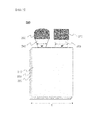
- FIGS. 1 to 8 are views respectively illustrating electrode assemblies 100, 200, 300, 400, 500, 600, 700 and 800 according to embodiments of the present invention.
- the electrode assemblies 100, 200, 300, 400, 500, 600, 700 and 800 respectively include stacked structures including cathode plates 110, 210, 310, 410, 510, 610, 710 and 810 from which cathode tabs 140, 240, 340, 440, 540, 640, 740 and 840 protrude, anode plates 120, 220, 320, 420, 520, 620, 720 and 820 from which anode tabs 150, 250, 350, 450, 550, 650, 750 and 850 protrude, and separators 130, 230, 330, 430, 530, 630, 730 and 830 disposed between the cathode plates 110, 210, 310, 410, 510, 610, 710 and 810 and the anode plates 120, 220, 320, 420, 520, 620, 720 and 820, cathode leads 160, 260, 360, 460, 560, 660, 760 and 860
- the cathode tabs 140 and 240 when viewed in plan view, have a trapezoidal shape, the anode tabs 150 and 250 have a rectangular shape, the cathode leads 160 and 260 have a shape with an arc end portion, and the anode leads 170 and 270 have a rectangular shape.
- widths w and w' of the respective cathode tabs 140 and 240 and the respective anode tabs 150 and 250 are approximately 15% a length 1 of electrode surfaces with the tabs formed thereon.
- the widths w and w' thereof are approximately 35%. That is, the widths w and w' of the respective cathode tabs 140 and 240 and the respective anode tabs 150 and 250 are within a range of 5% to 45%.
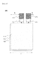
- the cathode tab 340 when viewed in plan view, has a trapezoidal shape, the anode tab 350 has a rectangular shape, the cathode lead 360 has a bent structure, and the anode lead 370 has a rectangular shape.
- the cathode lead 360 and the anode lead 370 are asymmetrically (A ⁇ B) positioned such that the cathode and anode leads 360 and 370 have different distances from an axis passing through the center of the electrode in the up and down direction and thus it is also easy to distinguish the cathode lead 360 from the anode lead 370.
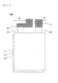
- the cathode tabs 440 and 540 and the anode tabs 450 and 550 are respectively disposed on opposite end portions of the electrode assembly 400 and on opposite end portions of the electrode assembly 500.
- the cathode tabs 440 and 540 and the anode tabs 450 and 550 have different shapes and the cathode leads 460 and 560 and the anode leads 470 and 570 also have different shapes.
- the widths w and w' of the respective cathode tabs 440 and 540 and the respective anode tabs 450 and 550 are approximately 15% a length 1 of electrode surfaces with the tabs formed thereon.
- the widths w and w' thereof are approximately 70% to 80%. That is, the widths w and w' of the respective cathode tabs 440 and 540 and the respective anode tabs 450 and 550 are within a range of 10% to 80% the length of the electrode surfaces.
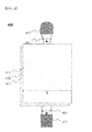
- the electrode assemblies 600 and 700 and the electrode assemblies 100 and 200 of FIGS. 1 and 2 have different structures in that the cathode tabs 640 and 740 and the anode tabs 650 and 750 have the same shape, but are asymmetrically (A ⁇ B) positioned. Thus, it is easy to distinguish the cathode tabs 640 and 740 from the anode tabs 650 and 750.
- the cathode leads 660 and 760 and the anode leads 670 and 770 have the same shape, according to the positions of the electrode tabs 640 and 650 and 740 and 750, the two electrode leads 660 and 670 and 760 and 770 are also asymmetrically (A ⁇ B) positioned such that the two electrode leads have different distances from an axis passing through the center of the electrode in the up and down direction.
- a ⁇ B asymmetrically
- the widths w and w' of the respective cathode tabs 640 and 740 and the respective anode tabs 650 and 750 are approximately 15% a length 1 of electrode surfaces with the tabs formed thereon.
- the width w of the cathode tab 740 is about 25% the length 1 of electrode surfaces and the width w' of the anode tab 750 is about 15% the length 1 of electrode surfaces. That is, the widths w and w' of the respective cathode and anode tabs may be identical or different within a range of 5% to 45%.
- the electrode assembly 800 and the electrode assemblies 600 and 700 of FIGS. 6 and 7 have different structures in that, when viewed in plan view, the cathode lead 860 has a shape with an arc end portion and the anode lead 870 has a rectangular shape. That is, even when the cathode tab 840 and the anode tab 850 are asymmetrically positioned, it may be easy to distinguish the cathode lead 860 from the anode lead 870 by making the electrode leads 860 and 870 have different shapes.
- cathode tabs and anode tabs have different shapes or are asymmetrically positioned with respect to electrode surfaces with the tabs formed thereon and thus cross-welding may be prevented.
- cathode and anode leads have different shapes or are asymmetrically positioned with respect to the electrode surfaces, whereby confusion of the positions of a cathode and an anode during module assembly or wiring for electrical connection may be addressed.
- widths of the cathode and anode tabs are formed to predetermined sizes based on the length of the electrode surfaces and, accordingly, resistance decreases, which reduces heat generation of a battery.
Applications Claiming Priority (3)
| Application Number | Priority Date | Filing Date | Title |
|---|---|---|---|
| KR20120039246 | 2012-04-16 | ||
| KR20120039351 | 2012-04-16 | ||
| PCT/KR2013/003205 WO2013157827A1 (fr) | 2012-04-16 | 2013-04-16 | Ensemble d'électrodes comprenant une électrode positive et une électrode négative de formes différentes, et batterie rechargeable |
Publications (3)
| Publication Number | Publication Date |
|---|---|
| EP2802027A1 true EP2802027A1 (fr) | 2014-11-12 |
| EP2802027A4 EP2802027A4 (fr) | 2016-03-02 |
| EP2802027B1 EP2802027B1 (fr) | 2018-05-30 |
Family
ID=49383715
Family Applications (1)
| Application Number | Title | Priority Date | Filing Date |
|---|---|---|---|
| EP13777711.6A Active EP2802027B1 (fr) | 2012-04-16 | 2013-04-16 | Ensemble d'électrodes comprenant une électrode positive et une électrode négative de formes différentes, et batterie rechargeable |
Country Status (6)
| Country | Link |
|---|---|
| US (1) | US20140349181A1 (fr) |
| EP (1) | EP2802027B1 (fr) |
| JP (1) | JP6313227B2 (fr) |
| KR (2) | KR20130116836A (fr) |
| CN (1) | CN104137304B (fr) |
| WO (1) | WO2013157827A1 (fr) |
Cited By (2)
| Publication number | Priority date | Publication date | Assignee | Title |
|---|---|---|---|---|
| EP2942832A4 (fr) * | 2014-01-28 | 2016-03-30 | Lg Chemical Ltd | Ensemble électrode et élément de batterie le comprenant |
| WO2019025419A1 (fr) * | 2017-08-02 | 2019-02-07 | Robert Bosch Gmbh | Élément de batterie comprenant une partie saillante de couche d'anode et/ou une partie saillante de couche de cathode mise en contact côté séparation et/ou côté frontal |
Families Citing this family (13)
| Publication number | Priority date | Publication date | Assignee | Title |
|---|---|---|---|---|
| KR102324345B1 (ko) * | 2015-01-28 | 2021-11-10 | 삼성에스디아이 주식회사 | 이차 전지 |
| JP6588241B2 (ja) * | 2015-06-04 | 2019-10-09 | 古河電池株式会社 | 鉛蓄電池 |
| KR102018849B1 (ko) | 2015-11-11 | 2019-09-05 | 주식회사 엘지화학 | 돌출 연장부와 탭 연결부를 구비한 전극 리드를 포함하고 있는 전지셀 |
| AU2017217661B2 (en) * | 2016-02-11 | 2018-11-15 | The Noco Company | Battery connector device for a battery jump starting device |
| JP6737218B2 (ja) * | 2017-03-31 | 2020-08-05 | Tdk株式会社 | 非水電解液二次電池 |
| US20200220119A1 (en) * | 2017-10-06 | 2020-07-09 | Nec Corporation | Film-covered battery, battery pack and method for manufacturing the film-covered battery |
| CN108428849B (zh) * | 2017-11-22 | 2024-01-16 | 宁德时代新能源科技股份有限公司 | 电极构件、电极组件和充电电池 |
| KR102523098B1 (ko) * | 2018-06-22 | 2023-04-17 | 주식회사 엘지에너지솔루션 | 이차 전지 및 이를 포함한 배터리 모듈 |
| US11276873B2 (en) | 2019-04-15 | 2022-03-15 | Sk Innovation Co., Ltd. | Superwide pouch type secondary battery with double tabs |
| JP2021051944A (ja) * | 2019-09-25 | 2021-04-01 | 積水化学工業株式会社 | 蓄電素子及び蓄電素子の製造方法 |
| KR102570970B1 (ko) * | 2020-03-20 | 2023-08-25 | 삼성에스디아이 주식회사 | 전극 조립체 |
| CN111575532B (zh) * | 2020-07-01 | 2021-10-08 | 江西理工大学 | 一种Bi取代的Mn缺位Mn2Sb基合金及其制备方法和应用 |
| CN116387766B (zh) * | 2023-06-05 | 2023-08-25 | 中创新航科技集团股份有限公司 | 圆柱电池、电池组 |
Family Cites Families (33)
| Publication number | Priority date | Publication date | Assignee | Title |
|---|---|---|---|---|
| JP2592362Y2 (ja) * | 1993-08-25 | 1999-03-17 | 株式会社ユアサコーポレーション | リチウム電池 |
| FR2787925B1 (fr) * | 1998-12-24 | 2001-03-09 | Cit Alcatel | Generateur electrochimique dans lequel une electrode a un bord renforce par un feuillard |
| JP3062384U (ja) * | 1999-03-24 | 1999-10-08 | 旭化成工業株式会社 | 非水系二次電池のリ―ド構造 |
| KR100483994B1 (ko) * | 2002-06-12 | 2005-04-18 | 주식회사 이글피쳐코캄 | 리튬 2차 전지용 크루드 셀의 전극탭 처리 방법 및 그에따른 크루드 셀 및 이를 채용한 리튬 2차 전지 |
| JP4635404B2 (ja) * | 2002-08-12 | 2011-02-23 | ソニー株式会社 | 非水電解質電池 |
| KR100515837B1 (ko) * | 2003-06-21 | 2005-09-21 | 삼성에스디아이 주식회사 | 파우치형 이차 전지용 전극 조립체 및 이를 구비한파우치형 이차 전지 |
| JP2005149882A (ja) * | 2003-11-14 | 2005-06-09 | Sii Micro Parts Ltd | 電気化学セル及びその製造方法 |
| JP4688435B2 (ja) * | 2004-05-17 | 2011-05-25 | セイコーインスツル株式会社 | コイン型またはボタン型の端子付電気化学セル |
| JP2006196428A (ja) * | 2004-05-31 | 2006-07-27 | Nissan Motor Co Ltd | 組電池およびその製造方法 |
| US20080044728A1 (en) * | 2004-10-29 | 2008-02-21 | Medtronic, Inc. | Lithium-ion battery |
| JP4734912B2 (ja) * | 2004-12-17 | 2011-07-27 | 日産自動車株式会社 | リチウムイオン電池およびその製造方法 |
| KR100688732B1 (ko) * | 2005-03-30 | 2007-03-02 | 에스케이 주식회사 | 구형 망간탄산화물의 제조방법 및 그 제조물 |
| JP4977375B2 (ja) * | 2006-02-15 | 2012-07-18 | Necエナジーデバイス株式会社 | リチウムイオン電池およびそれを用いた組電池 |
| JP5114036B2 (ja) * | 2006-09-08 | 2013-01-09 | Necエナジーデバイス株式会社 | 積層型電池の製造方法 |
| JP4775226B2 (ja) * | 2006-10-24 | 2011-09-21 | トヨタ自動車株式会社 | 蓄電装置の製造方法 |
| KR100891383B1 (ko) * | 2007-05-21 | 2009-04-02 | 삼성에스디아이 주식회사 | 파우치형 이차 전지 |
| KR101156955B1 (ko) * | 2007-06-14 | 2012-06-20 | 주식회사 엘지화학 | 안전성이 향상된 전극조립체 및 이를 포함하는 이차전지 |
| KR101042613B1 (ko) * | 2007-06-22 | 2011-06-20 | 주식회사 엘지화학 | 우수한 전기전도성의 음극재 및 이를 포함하는 고출력이차전지 |
| US20090208816A1 (en) * | 2008-01-31 | 2009-08-20 | Viavattine Joseph J | Properly positioning stacked plate electrode for high volume assembly |
| JP5321783B2 (ja) * | 2008-03-04 | 2013-10-23 | 株式会社東芝 | 非水電解質二次電池および組電池 |
| KR101015834B1 (ko) * | 2009-01-06 | 2011-02-23 | 에스비리모티브 주식회사 | 전지 모듈 |
| KR101139016B1 (ko) * | 2009-06-17 | 2012-04-26 | 주식회사 엘지화학 | 다방향성 리드-탭 구조를 가진 리튬 이차 전지 |
| JP2011048967A (ja) * | 2009-08-26 | 2011-03-10 | Nec Energy Devices Ltd | 積層型二次電池および製造方法 |
| JP5676095B2 (ja) * | 2009-11-19 | 2015-02-25 | Necエナジーデバイス株式会社 | 積層型二次電池 |
| KR101108183B1 (ko) * | 2009-12-11 | 2012-01-31 | 삼성에스디아이 주식회사 | 단위 배터리 모듈 및 배터리 모듈 패키지 |
| KR101292252B1 (ko) * | 2010-03-08 | 2013-08-01 | 히다치 막셀 가부시키가이샤 | 리튬 이온 이차 전지 |
| US20110316664A1 (en) * | 2010-06-28 | 2011-12-29 | Andrew Olcott | Remote control for sound system |
| JP2012014935A (ja) * | 2010-06-30 | 2012-01-19 | Mitsubishi Heavy Ind Ltd | 電池 |
| JP2012038495A (ja) * | 2010-08-05 | 2012-02-23 | Hitachi Maxell Energy Ltd | 非水電解質電池モジュール |
| JP5175906B2 (ja) * | 2010-09-07 | 2013-04-03 | 株式会社東芝 | 非水電解質二次電池及び電池パック |
| CN102082290A (zh) * | 2010-12-30 | 2011-06-01 | 奇瑞汽车股份有限公司 | 一种高电压高比能量锂离子电池及其制备方法 |
| JP5887472B2 (ja) * | 2011-02-17 | 2016-03-16 | パナソニックIpマネジメント株式会社 | 電子部品の製造方法 |
| KR101517054B1 (ko) * | 2012-04-16 | 2015-05-06 | 주식회사 엘지화학 | 양극과 음극의 용접 부위 형상이 다른 전극조립체 및 이를 포함하는 이차전지 |
-
2013
- 2013-04-16 JP JP2014559844A patent/JP6313227B2/ja active Active
- 2013-04-16 KR KR20130041905A patent/KR20130116836A/ko not_active IP Right Cessation
- 2013-04-16 WO PCT/KR2013/003205 patent/WO2013157827A1/fr active Application Filing
- 2013-04-16 CN CN201380011052.2A patent/CN104137304B/zh active Active
- 2013-04-16 EP EP13777711.6A patent/EP2802027B1/fr active Active
-
2014
- 2014-08-14 US US14/459,453 patent/US20140349181A1/en not_active Abandoned
-
2015
- 2015-07-07 KR KR1020150096435A patent/KR20150086218A/ko not_active Application Discontinuation
Cited By (2)
| Publication number | Priority date | Publication date | Assignee | Title |
|---|---|---|---|---|
| EP2942832A4 (fr) * | 2014-01-28 | 2016-03-30 | Lg Chemical Ltd | Ensemble électrode et élément de batterie le comprenant |
| WO2019025419A1 (fr) * | 2017-08-02 | 2019-02-07 | Robert Bosch Gmbh | Élément de batterie comprenant une partie saillante de couche d'anode et/ou une partie saillante de couche de cathode mise en contact côté séparation et/ou côté frontal |
Also Published As
| Publication number | Publication date |
|---|---|
| CN104137304A (zh) | 2014-11-05 |
| EP2802027B1 (fr) | 2018-05-30 |
| JP2015513183A (ja) | 2015-04-30 |
| EP2802027A4 (fr) | 2016-03-02 |
| JP6313227B2 (ja) | 2018-04-18 |
| CN104137304B (zh) | 2018-02-06 |
| US20140349181A1 (en) | 2014-11-27 |
| KR20150086218A (ko) | 2015-07-27 |
| WO2013157827A1 (fr) | 2013-10-24 |
| KR20130116836A (ko) | 2013-10-24 |
Similar Documents
| Publication | Publication Date | Title |
|---|---|---|
| EP2802027B1 (fr) | Ensemble d'électrodes comprenant une électrode positive et une électrode négative de formes différentes, et batterie rechargeable | |
| EP2804239B1 (fr) | Ensemble d'électrodes présentant des formes différentes de partie de soudure d'anode et de cathode et batterie rechargeable le comprenant | |
| US9780359B2 (en) | Method of manufacturing electrode for lithium secondary battery and electrode manufactured using the same | |
| US10122011B2 (en) | Multi layered electrode and method of manufacturing the same | |
| US9786916B2 (en) | Electrode and secondary battery including the same | |
| US9673444B2 (en) | Method of manufacturing electrode for lithium secondary battery and electrode manufactured using the same | |
| US9899663B2 (en) | Lithium secondary battery with excellent performance | |
| US10026952B2 (en) | Method of manufacturing electrode for lithium secondary battery and electrode manufactured using the same | |
| US10153480B2 (en) | Electrode for secondary battery and secondary battery including the same | |
| KR102082467B1 (ko) | 집전체 중심 부위에 높은 활물질 로딩량을 가지는 전극을 포함하는 전극조립체 | |
| US9564635B2 (en) | Lithium secondary battery with excellent performance | |
| US9825293B2 (en) | Lithium battery having higher performance | |
| KR102026292B1 (ko) | 활물질 로딩량의 구배를 가진 전극을 포함하는 전극조립체 | |
| US10468726B2 (en) | Negative electrode for preventing deposition of manganese and battery cell including the same | |
| KR101262086B1 (ko) | 내부 단락을 방지할 수 있는 구조의 이차전지 |
Legal Events
| Date | Code | Title | Description |
|---|---|---|---|
| PUAI | Public reference made under article 153(3) epc to a published international application that has entered the european phase |
Free format text: ORIGINAL CODE: 0009012 |
|
| 17P | Request for examination filed |
Effective date: 20140807 |
|
| AK | Designated contracting states |
Kind code of ref document: A1 Designated state(s): AL AT BE BG CH CY CZ DE DK EE ES FI FR GB GR HR HU IE IS IT LI LT LU LV MC MK MT NL NO PL PT RO RS SE SI SK SM TR |
|
| DAX | Request for extension of the european patent (deleted) | ||
| RIC1 | Information provided on ipc code assigned before grant |
Ipc: H01M 2/16 20060101ALI20150811BHEP Ipc: H01M 2/26 20060101AFI20150811BHEP Ipc: H01M 2/30 20060101ALI20150811BHEP Ipc: H01M 10/6553 20140101ALI20150811BHEP |
|
| RA4 | Supplementary search report drawn up and despatched (corrected) |
Effective date: 20160201 |
|
| RIC1 | Information provided on ipc code assigned before grant |
Ipc: H01M 10/6553 20140101ALI20160126BHEP Ipc: H01M 10/0525 20100101ALI20160126BHEP Ipc: H01M 4/505 20100101ALI20160126BHEP Ipc: H01M 2/16 20060101ALI20160126BHEP Ipc: H01M 4/485 20100101ALI20160126BHEP Ipc: H01M 2/30 20060101ALI20160126BHEP Ipc: H01M 4/525 20100101ALI20160126BHEP Ipc: H01M 2/26 20060101AFI20160126BHEP |
|
| 17Q | First examination report despatched |
Effective date: 20160831 |
|
| STAA | Information on the status of an ep patent application or granted ep patent |
Free format text: STATUS: EXAMINATION IS IN PROGRESS |
|
| GRAP | Despatch of communication of intention to grant a patent |
Free format text: ORIGINAL CODE: EPIDOSNIGR1 |
|
| STAA | Information on the status of an ep patent application or granted ep patent |
Free format text: STATUS: GRANT OF PATENT IS INTENDED |
|
| INTG | Intention to grant announced |
Effective date: 20180129 |
|
| GRAS | Grant fee paid |
Free format text: ORIGINAL CODE: EPIDOSNIGR3 |
|
| GRAA | (expected) grant |
Free format text: ORIGINAL CODE: 0009210 |
|
| STAA | Information on the status of an ep patent application or granted ep patent |
Free format text: STATUS: THE PATENT HAS BEEN GRANTED |
|
| AK | Designated contracting states |
Kind code of ref document: B1 Designated state(s): AL AT BE BG CH CY CZ DE DK EE ES FI FR GB GR HR HU IE IS IT LI LT LU LV MC MK MT NL NO PL PT RO RS SE SI SK SM TR |
|
| REG | Reference to a national code |
Ref country code: GB Ref legal event code: FG4D |
|
| REG | Reference to a national code |
Ref country code: CH Ref legal event code: EP |
|
| REG | Reference to a national code |
Ref country code: AT Ref legal event code: REF Ref document number: 1004518 Country of ref document: AT Kind code of ref document: T Effective date: 20180615 |
|
| REG | Reference to a national code |
Ref country code: IE Ref legal event code: FG4D |
|
| REG | Reference to a national code |
Ref country code: DE Ref legal event code: R096 Ref document number: 602013038247 Country of ref document: DE |
|
| RAP2 | Party data changed (patent owner data changed or rights of a patent transferred) |
Owner name: LG CHEM, LTD. |
|
| REG | Reference to a national code |
Ref country code: NL Ref legal event code: MP Effective date: 20180530 |
|
| REG | Reference to a national code |
Ref country code: LT Ref legal event code: MG4D |
|
| PG25 | Lapsed in a contracting state [announced via postgrant information from national office to epo] |
Ref country code: CY Free format text: LAPSE BECAUSE OF FAILURE TO SUBMIT A TRANSLATION OF THE DESCRIPTION OR TO PAY THE FEE WITHIN THE PRESCRIBED TIME-LIMIT Effective date: 20180530 Ref country code: LT Free format text: LAPSE BECAUSE OF FAILURE TO SUBMIT A TRANSLATION OF THE DESCRIPTION OR TO PAY THE FEE WITHIN THE PRESCRIBED TIME-LIMIT Effective date: 20180530 Ref country code: BG Free format text: LAPSE BECAUSE OF FAILURE TO SUBMIT A TRANSLATION OF THE DESCRIPTION OR TO PAY THE FEE WITHIN THE PRESCRIBED TIME-LIMIT Effective date: 20180830 Ref country code: FI Free format text: LAPSE BECAUSE OF FAILURE TO SUBMIT A TRANSLATION OF THE DESCRIPTION OR TO PAY THE FEE WITHIN THE PRESCRIBED TIME-LIMIT Effective date: 20180530 Ref country code: NO Free format text: LAPSE BECAUSE OF FAILURE TO SUBMIT A TRANSLATION OF THE DESCRIPTION OR TO PAY THE FEE WITHIN THE PRESCRIBED TIME-LIMIT Effective date: 20180830 Ref country code: SE Free format text: LAPSE BECAUSE OF FAILURE TO SUBMIT A TRANSLATION OF THE DESCRIPTION OR TO PAY THE FEE WITHIN THE PRESCRIBED TIME-LIMIT Effective date: 20180530 Ref country code: ES Free format text: LAPSE BECAUSE OF FAILURE TO SUBMIT A TRANSLATION OF THE DESCRIPTION OR TO PAY THE FEE WITHIN THE PRESCRIBED TIME-LIMIT Effective date: 20180530 |
|
| PG25 | Lapsed in a contracting state [announced via postgrant information from national office to epo] |
Ref country code: GR Free format text: LAPSE BECAUSE OF FAILURE TO SUBMIT A TRANSLATION OF THE DESCRIPTION OR TO PAY THE FEE WITHIN THE PRESCRIBED TIME-LIMIT Effective date: 20180831 Ref country code: HR Free format text: LAPSE BECAUSE OF FAILURE TO SUBMIT A TRANSLATION OF THE DESCRIPTION OR TO PAY THE FEE WITHIN THE PRESCRIBED TIME-LIMIT Effective date: 20180530 Ref country code: LV Free format text: LAPSE BECAUSE OF FAILURE TO SUBMIT A TRANSLATION OF THE DESCRIPTION OR TO PAY THE FEE WITHIN THE PRESCRIBED TIME-LIMIT Effective date: 20180530 Ref country code: RS Free format text: LAPSE BECAUSE OF FAILURE TO SUBMIT A TRANSLATION OF THE DESCRIPTION OR TO PAY THE FEE WITHIN THE PRESCRIBED TIME-LIMIT Effective date: 20180530 |
|
| REG | Reference to a national code |
Ref country code: AT Ref legal event code: MK05 Ref document number: 1004518 Country of ref document: AT Kind code of ref document: T Effective date: 20180530 |
|
| PG25 | Lapsed in a contracting state [announced via postgrant information from national office to epo] |
Ref country code: NL Free format text: LAPSE BECAUSE OF FAILURE TO SUBMIT A TRANSLATION OF THE DESCRIPTION OR TO PAY THE FEE WITHIN THE PRESCRIBED TIME-LIMIT Effective date: 20180530 |
|
| PG25 | Lapsed in a contracting state [announced via postgrant information from national office to epo] |
Ref country code: DK Free format text: LAPSE BECAUSE OF FAILURE TO SUBMIT A TRANSLATION OF THE DESCRIPTION OR TO PAY THE FEE WITHIN THE PRESCRIBED TIME-LIMIT Effective date: 20180530 Ref country code: AT Free format text: LAPSE BECAUSE OF FAILURE TO SUBMIT A TRANSLATION OF THE DESCRIPTION OR TO PAY THE FEE WITHIN THE PRESCRIBED TIME-LIMIT Effective date: 20180530 Ref country code: EE Free format text: LAPSE BECAUSE OF FAILURE TO SUBMIT A TRANSLATION OF THE DESCRIPTION OR TO PAY THE FEE WITHIN THE PRESCRIBED TIME-LIMIT Effective date: 20180530 Ref country code: RO Free format text: LAPSE BECAUSE OF FAILURE TO SUBMIT A TRANSLATION OF THE DESCRIPTION OR TO PAY THE FEE WITHIN THE PRESCRIBED TIME-LIMIT Effective date: 20180530 Ref country code: SK Free format text: LAPSE BECAUSE OF FAILURE TO SUBMIT A TRANSLATION OF THE DESCRIPTION OR TO PAY THE FEE WITHIN THE PRESCRIBED TIME-LIMIT Effective date: 20180530 Ref country code: CZ Free format text: LAPSE BECAUSE OF FAILURE TO SUBMIT A TRANSLATION OF THE DESCRIPTION OR TO PAY THE FEE WITHIN THE PRESCRIBED TIME-LIMIT Effective date: 20180530 Ref country code: PL Free format text: LAPSE BECAUSE OF FAILURE TO SUBMIT A TRANSLATION OF THE DESCRIPTION OR TO PAY THE FEE WITHIN THE PRESCRIBED TIME-LIMIT Effective date: 20180530 |
|
| PG25 | Lapsed in a contracting state [announced via postgrant information from national office to epo] |
Ref country code: SM Free format text: LAPSE BECAUSE OF FAILURE TO SUBMIT A TRANSLATION OF THE DESCRIPTION OR TO PAY THE FEE WITHIN THE PRESCRIBED TIME-LIMIT Effective date: 20180530 Ref country code: IT Free format text: LAPSE BECAUSE OF FAILURE TO SUBMIT A TRANSLATION OF THE DESCRIPTION OR TO PAY THE FEE WITHIN THE PRESCRIBED TIME-LIMIT Effective date: 20180530 |
|
| REG | Reference to a national code |
Ref country code: DE Ref legal event code: R097 Ref document number: 602013038247 Country of ref document: DE |
|
| PLBE | No opposition filed within time limit |
Free format text: ORIGINAL CODE: 0009261 |
|
| STAA | Information on the status of an ep patent application or granted ep patent |
Free format text: STATUS: NO OPPOSITION FILED WITHIN TIME LIMIT |
|
| 26N | No opposition filed |
Effective date: 20190301 |
|
| PG25 | Lapsed in a contracting state [announced via postgrant information from national office to epo] |
Ref country code: SI Free format text: LAPSE BECAUSE OF FAILURE TO SUBMIT A TRANSLATION OF THE DESCRIPTION OR TO PAY THE FEE WITHIN THE PRESCRIBED TIME-LIMIT Effective date: 20180530 |
|
| PG25 | Lapsed in a contracting state [announced via postgrant information from national office to epo] |
Ref country code: AL Free format text: LAPSE BECAUSE OF FAILURE TO SUBMIT A TRANSLATION OF THE DESCRIPTION OR TO PAY THE FEE WITHIN THE PRESCRIBED TIME-LIMIT Effective date: 20180530 |
|
| REG | Reference to a national code |
Ref country code: CH Ref legal event code: PL |
|
| REG | Reference to a national code |
Ref country code: BE Ref legal event code: MM Effective date: 20190430 |
|
| PG25 | Lapsed in a contracting state [announced via postgrant information from national office to epo] |
Ref country code: MC Free format text: LAPSE BECAUSE OF FAILURE TO SUBMIT A TRANSLATION OF THE DESCRIPTION OR TO PAY THE FEE WITHIN THE PRESCRIBED TIME-LIMIT Effective date: 20180530 Ref country code: LU Free format text: LAPSE BECAUSE OF NON-PAYMENT OF DUE FEES Effective date: 20190416 |
|
| PG25 | Lapsed in a contracting state [announced via postgrant information from national office to epo] |
Ref country code: LI Free format text: LAPSE BECAUSE OF NON-PAYMENT OF DUE FEES Effective date: 20190430 Ref country code: CH Free format text: LAPSE BECAUSE OF NON-PAYMENT OF DUE FEES Effective date: 20190430 |
|
| PG25 | Lapsed in a contracting state [announced via postgrant information from national office to epo] |
Ref country code: BE Free format text: LAPSE BECAUSE OF NON-PAYMENT OF DUE FEES Effective date: 20190430 |
|
| PG25 | Lapsed in a contracting state [announced via postgrant information from national office to epo] |
Ref country code: TR Free format text: LAPSE BECAUSE OF FAILURE TO SUBMIT A TRANSLATION OF THE DESCRIPTION OR TO PAY THE FEE WITHIN THE PRESCRIBED TIME-LIMIT Effective date: 20180530 |
|
| PG25 | Lapsed in a contracting state [announced via postgrant information from national office to epo] |
Ref country code: IE Free format text: LAPSE BECAUSE OF NON-PAYMENT OF DUE FEES Effective date: 20190416 |
|
| PG25 | Lapsed in a contracting state [announced via postgrant information from national office to epo] |
Ref country code: PT Free format text: LAPSE BECAUSE OF FAILURE TO SUBMIT A TRANSLATION OF THE DESCRIPTION OR TO PAY THE FEE WITHIN THE PRESCRIBED TIME-LIMIT Effective date: 20181001 |
|
| REG | Reference to a national code |
Ref country code: DE Ref legal event code: R079 Ref document number: 602013038247 Country of ref document: DE Free format text: PREVIOUS MAIN CLASS: H01M0002260000 Ipc: H01M0050531000 |
|
| PG25 | Lapsed in a contracting state [announced via postgrant information from national office to epo] |
Ref country code: IS Free format text: LAPSE BECAUSE OF FAILURE TO SUBMIT A TRANSLATION OF THE DESCRIPTION OR TO PAY THE FEE WITHIN THE PRESCRIBED TIME-LIMIT Effective date: 20180930 |
|
| PG25 | Lapsed in a contracting state [announced via postgrant information from national office to epo] |
Ref country code: HU Free format text: LAPSE BECAUSE OF FAILURE TO SUBMIT A TRANSLATION OF THE DESCRIPTION OR TO PAY THE FEE WITHIN THE PRESCRIBED TIME-LIMIT; INVALID AB INITIO Effective date: 20130416 Ref country code: MT Free format text: LAPSE BECAUSE OF FAILURE TO SUBMIT A TRANSLATION OF THE DESCRIPTION OR TO PAY THE FEE WITHIN THE PRESCRIBED TIME-LIMIT Effective date: 20180530 |
|
| PG25 | Lapsed in a contracting state [announced via postgrant information from national office to epo] |
Ref country code: MK Free format text: LAPSE BECAUSE OF FAILURE TO SUBMIT A TRANSLATION OF THE DESCRIPTION OR TO PAY THE FEE WITHIN THE PRESCRIBED TIME-LIMIT Effective date: 20180530 |
|
| PGFP | Annual fee paid to national office [announced via postgrant information from national office to epo] |
Ref country code: FR Payment date: 20230321 Year of fee payment: 11 |
|
| PGFP | Annual fee paid to national office [announced via postgrant information from national office to epo] |
Ref country code: GB Payment date: 20230320 Year of fee payment: 11 |
|
| P01 | Opt-out of the competence of the unified patent court (upc) registered |
Effective date: 20230323 |
|
| PGFP | Annual fee paid to national office [announced via postgrant information from national office to epo] |
Ref country code: DE Payment date: 20230320 Year of fee payment: 11 |
|
| REG | Reference to a national code |
Ref country code: GB Ref legal event code: 732E Free format text: REGISTERED BETWEEN 20230824 AND 20230831 |
|
| REG | Reference to a national code |
Ref country code: DE Ref legal event code: R081 Ref document number: 602013038247 Country of ref document: DE Owner name: LG ENERGY SOLUTION, LTD., KR Free format text: FORMER OWNER: LG CHEM, LTD., SEOUL, KR |
|
| PGFP | Annual fee paid to national office [announced via postgrant information from national office to epo] |
Ref country code: GB Payment date: 20240320 Year of fee payment: 12 |