EP2801655A1 - Wäschetrockner mit einem Bodenmodul - Google Patents
Wäschetrockner mit einem Bodenmodul Download PDFInfo
- Publication number
- EP2801655A1 EP2801655A1 EP14167317.8A EP14167317A EP2801655A1 EP 2801655 A1 EP2801655 A1 EP 2801655A1 EP 14167317 A EP14167317 A EP 14167317A EP 2801655 A1 EP2801655 A1 EP 2801655A1
- Authority
- EP
- European Patent Office
- Prior art keywords
- mounting frame
- floor module
- opening
- clothes dryer
- pump
- Prior art date
- Legal status (The legal status is an assumption and is not a legal conclusion. Google has not performed a legal analysis and makes no representation as to the accuracy of the status listed.)
- Granted
Links
Images




Classifications
-
- D—TEXTILES; PAPER
- D06—TREATMENT OF TEXTILES OR THE LIKE; LAUNDERING; FLEXIBLE MATERIALS NOT OTHERWISE PROVIDED FOR
- D06F—LAUNDERING, DRYING, IRONING, PRESSING OR FOLDING TEXTILE ARTICLES
- D06F58/00—Domestic laundry dryers
- D06F58/20—General details of domestic laundry dryers
-
- D—TEXTILES; PAPER
- D06—TREATMENT OF TEXTILES OR THE LIKE; LAUNDERING; FLEXIBLE MATERIALS NOT OTHERWISE PROVIDED FOR
- D06F—LAUNDERING, DRYING, IRONING, PRESSING OR FOLDING TEXTILE ARTICLES
- D06F58/00—Domestic laundry dryers
- D06F58/20—General details of domestic laundry dryers
- D06F58/24—Condensing arrangements
Definitions
- the invention relates to a tumble dryer with a floor module (1), which includes a condensation device (2) and a pump (3) for conveying the accumulated condensate, wherein the pump (3) is supported by a mounting frame (10), the one from has its level elevational circumferential edge approach (13).
- the floor module has a condensate collection housing with an opening for a pump device.
- the pump device is supported by a support body or mounting frame, which rests on the opening edge.
- the mounting frame is connected via a hinge with a cover, which covers the pump device and secured by a screw connection and a latching connection to the floor module.
- the mounting frame does not seal the opening of the condensate collection housing.
- the DE 89 12 184 U1 shows a condensate pump device for a tumble dryer in which the pump is supported by a cover for the condensate collection tank. This cover has a projecting into the condensate tank peripheral edge approach.
- the invention thus raises the problem of simplifying the installation of the condensate feed pump in a tumble dryer of the type mentioned and still ensure a tight fit of the pump.
- the mounting frame has a rising from its plane circumferential edge approach, which has in its end an excess over the opening.
- the marginal approach ensures that the mounting frame with a press fit into the opening can be inserted and therefore this hermetically seals without further elastomer seal.
- edge extension extends upwards in the operating state of the tumble dryer. It is also useful if the mounting frame is made with the edge approach as a one-piece injection molded part made of plastic. A simple installation and at the same time good sealing results when the edge approach is resilient due to its material thickness. At the edge approach, an outwardly projecting rib may be formed, preferably with triangular cross-section. As a result, dimensional tolerances are compensated.
- the mounting frame and the opening in the bottom module are round or elliptical. As a result, straight lines are avoided in which the edge approach can tilt inwards. In an elliptical embodiment, it is particularly advantageous if the excess of the marginal projection on the elliptical side with the larger radius is greater. In order to ensure a secure fit of the pump even when vibrations occur, it is advantageous if the mounting frame is held by a latching device in the opening. In addition, a stop limit the insertion depth of the mounting frame in the opening.
- FIG. 1 shows an overall view of a floor module 1 of an otherwise not shown tumble dryer, here a heat pump dryer.
- the module 1 includes, inter alia, a heat exchanger 2, is cooled in the hot moist air from the laundry drum, not shown here and thereby dehumidified by condensation.
- the condensate runs in the lower region of the floor module 1 and is conveyed from there by means of a condensate feed pump 3 via a hose 4 into a condensate collecting tank, not shown.
- FIG. 2 shows a plan view of a portion of the floor module 1 with removed condensate feed pump 3. It is an elliptical opening 5 can be seen, in which the pump 3 is used. In addition, two latching hooks 6 and three stops 7 can be seen in the figure, whose function will be explained later.
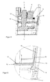
- FIGS. 3 to 7 a part of the floor module 1 and the pump 2 are shown shortly before their insertion into the opening 5.
- the pump motor 8 and the outlet 9 of the pump 3 can be seen.
- the pump 3 is mounted on an elliptical mounting frame 10 which holds the pump 3 in the region of the drive shaft (not shown) between the motor 8 and pump impeller 11, see in particular FIGS. 4 and 6 .
- the mounting frame 10 includes a flat surface 12 which extends horizontally in the installed state of the pump 3, which corresponds to the operating state of the tumble dryer.
- the planar surface 12 is surrounded by a peripheral edge projection 13, which extends from the plane of the planar part 12 upwards.
- Edge 12 and edge projection 13 are made in one piece in an injection molding of polypropylene. Due to the material and the relatively thin formation of the edge approach 13 this has a certain spring property.
- the edge projection 13 is inclined in its course outwards to the edge 14 of the opening 5 and thereby has an excess in its end region 15 with respect to the opening 5. This results in the insertion of the pump 3 in the opening 5, a press fit between the opening 5 and the edge extension 13, so that a liquid-tight fit is achieved.
- a comparison of Figures 5 and 7 shows that the inclination of the marginal projection 13 on the elliptical sides 16 and 17 with the larger radius is stronger. Since the elasticity of the marginal projection 13 on these pages 16 and 17 is greater, a uniform sealing force is achieved by the greater inclination in this area circumferentially.
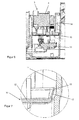
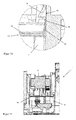
- FIGS. 8 to 12 show the pump 3 in the assembled state in this seat. It can be seen that the insertion depth of the mounting frame 10 is limited by the stops 7, see in particular the Figures 9 and 10 , These figures also show that the mounting frame 10 and thus the entire pump 3 is held in this position by the latching hooks 6.
Landscapes
- Engineering & Computer Science (AREA)
- Textile Engineering (AREA)
- Detail Structures Of Washing Machines And Dryers (AREA)
Abstract
Description
- Die Erfindung betrifft einen Wäschetrockner mit einem Bodenmodul (1), welches eine Kondensationseinrichtung (2) und eine Pumpe (3) zum Fördern des angefallenen Kondensats beinhaltet, wobei die Pumpe (3) von einem Einbaurahmen (10) getragen wird, der einen sich aus seiner Ebene erhebenden umlaufenden Randansatz (13) aufweist.
- Ein solcher Wäschetrockner ist aus der
EP 2 620 541 A1 bekannt. Das Bodenmodul weist ein Kondensatsammelgehäuse mit einer Öffnung für eine Pumpeneinrichtung auf. Die Pumpeneinrichtung wird von einem Tragkörper bzw. Einbaurahmen getragen, der auf dem Öffnungsrand aufliegt. Der Einbaurahmen ist über ein Scharnier mit einer Abdeckung verbunden, die die Pumpeneinrichtung abdeckt und über eine Schraubverbindung sowie eine Rastverbindung am Bodenmodul befestigt. Der Einbaurahmen schließt die Öffnung des Kondensatsammelgehäuses nicht dichtend ab. - Die
DE 89 12 184 U1 zeigt eine Kondensatpumpeneinrichtung für einen Wäschetrockner bei dem die Pumpe von einem Deckel für den Kondensatsammelbehälter getragen wird. Dieser Deckel weist einen in den Kondensatsammelbehälter ragenden umlaufenden Randansatz auf. - Außerdem ist ein von der Anmelderin als T 8866 WP hergestellter und vertriebener Wäschetrockner bekannt. Die Abdichtung des Einbaurahmens gegenüber der Öffnungswand im Bodenmodul erfolgt bei diesem Trockner mittels einer Polyurethan-Raupe, die vor dem Einbau der Pumpe auf den Rand des Einbaurahmens aufgetragen wird. Solche Dichtungen erhöhen den Montageaufwand und sind nicht immer prozesssicher.
- Der Erfindung stellt sich somit das Problem, bei einem Wäschetrockner der eingangs genannten Art die Montage der Kondensat-Förderpumpe zu vereinfachen und trotzdem einen dichten Sitz der Pumpe zu gewährleisten.
- Erfindungsgemäß wird dieses Problem durch einen Wäschetrockner mit den Merkmalen des Patentanspruchs 1 gelöst. Vorteilhafte Ausgestaltungen und Weiterbildungen der Erfindung ergeben sich aus den nachfolgenden Unteransprüchen.
- Die mit der Erfindung erreichbaren Vorteile ergeben sich dadurch, dass der Einbaurahmen einen sich aus seiner Ebene erhebenden umlaufenden Randansatz aufweist, welcher in seinem Endbereich ein Übermaß gegenüber der Öffnung aufweist. Der Randansatz gewährleistet, dass der Einbaurahmen mit Presssitz in die Öffnung einschiebbar ist und deshalb diese ohne weitere Elastomerdichtung luftdicht abschließt.
- Zum einfachen Einbau ist es vorteilhaft, wenn der Randansatz sich im Betriebszustand des Wäschetrockners nach oben erstreckt. Es ist außerdem zweckmäßig, wenn der Einbaurahmen mit dem Randansatz als einstückiges Spritzgussteil aus Kunststoff gefertigt ist. Eine einfache Montage und gleichzeitig gute Abdichtung ergibt sich, wenn der Randansatz aufgrund seiner Materialstärke federnd ausgebildet ist. An den Randansatz kann eine nach außen ragende Rippe angeformt sein, vorzugsweise mit dreieckigem Querschnitt. Hierdurch werden maßliche Toleranzen ausgeglichen.
- Es ist auch vorteilhaft, wenn der Einbaurahmen und die Öffnung im Bodenmodul rund oder elliptisch ausgebildet sind. Hierdurch werden Geraden vermieden, in denen der Randansatz nach innen kippen kann. Bei einer elliptischen Ausführungsform ist es besonders vorteilhaft, wenn das Übermaß des Randansatzes auf den Ellipsenseiten mit dem größeren Radius größer ist. Um einen sicheren Sitz der Pumpe auch bei auftretenden Schwingungen zu gewährleisten, ist es vorteilhaft, wenn der Einbaurahmen durch eine Rasteinrichtung in der Öffnung gehalten ist. Außerdem kann ein Anschlag die Einschubtiefe des Einbaurahmens in die Öffnung begrenzen.
- Ein Ausführungsbeispiel der Erfindung ist in den Zeichnungen rein schematisch dargestellt und wird nachfolgend näher beschrieben. Es zeigt
- Figur 1
- eine Gesamtansicht eines Bodenmoduls eines Wäschetrockners;
- Figur 2
- einen Ausschnitt aus dem Bodenmodul in der Draufsicht ohne Kondensat-Förderpumpe;
- Figur 3
- einen Ausschnitt aus dem Bodenmodul mit der Kondensat-Förderpumpe kurz vor der Montage;
- Figur 4
- einen Längsschnitt durch
Figur 3 ; - Figur 5
- einen vergrößerten Ausschnitt aus
Figur 4 ; - Figur 6
- einen Querschnitt durch
Figur 3 ; - Figur 7
- einen vergrößerten Ausschnitt aus
Figur 6 ; - Figur 8
- einen Ausschnitt aus dem Bodenmodul mit montierter Kondensat-Förderpumpe;
- Figur 9
- einen Längsschnitt durch
Figur 8 ; - Figur 10
- einen vergrößerten Ausschnitt aus
Figur 9 ; - Figur 11
- einen Querschnitt durch
Figur 8 ; - Figur 12
- einen vergrößerten Ausschnitt aus
Figur 11 . -
Figur 1 zeigt eine Gesamtansicht eines Bodenmoduls 1 eines ansonsten nicht näher dargestellten Wäschetrockners, hier eines Wärmepumpentrockners. Das Modul 1 beinhaltet unter anderem einen Wärmetauscher 2, in dem heiße feuchte Luft aus der hier nicht dargestellten Wäschetrommel abgekühlt und dabei durch Kondensation entfeuchtet wird. Das Kondensat läuft in den unteren Bereich des Bodenmoduls 1 und wird von dort mittels einer Kondensat-Förderpumpe 3 über einen Schlauch 4 in einen nicht dargestellten KondensatSammelbehälter gefördert. -
Figur 2 zeigt eine Draufsicht auf einen Teilbereich des Bodenmoduls 1 bei entfernter Kondensat-Förderpumpe 3. Es ist eine elliptische Öffnung 5 erkennbar, in die die Pumpe 3 eingesetzt wird. Außerdem sind in der Figur zwei Rasthaken 6 und drei Anschläge 7 erkennbar, deren Funktion später erläutert wird. - In den
Figuren 3 bis 7 sind ein Teil des Bodenmoduls 1 und die Pumpe 2 kurz vor ihrem Einsetzen in die Öffnung 5 dargestellt. In der Draufsicht (Figur 3 ) ist der Pumpenmotor 8 und der Auslassstutzen 9 der Pumpe 3 erkennbar. Die Pumpe 3 ist auf einem elliptischen Einbaurahmen 10 befestigt, der die Pumpe 3 im Bereich der Antriebswelle (nicht dargestellt) zwischen Motor 8 und Pumpenlaufrad 11 hält, siehe insbesondereFiguren 4 und6 . Der Einbaurahmen 10 umfasst eine plane Fläche 12, die sich im gezeigten Einbauzustand der Pumpe 3, der dem Betriebszustand des Wäschetrockners entspricht, waagerecht erstreckt. Die plane Fläche 12 ist von einem umlaufenden Randansatz 13 umgeben, der sich aus der Ebene des planen Teils 12 heraus nach oben erstreckt. Fläche 12 und Randansatz 13 sind einstückig in einem Spritzgießverfahren aus Polypropylen hergestellt. Aufgrund des Materials und der relativ dünnen Ausbildung des Randansatzes 13 besitzt dieser eine gewisse Federeigenschaft. Außerdem ist insbesondere aus den Detailansichten 5 und 7 erkennbar, dass der Randansatz 13 in seinem Verlauf nach außen zum Rand 14 der Öffnung 5 geneigt ist und dadurch in seinem Endbereich 15 ein Übermaß gegenüber der Öffnung 5 aufweist. Hierdurch ergibt sich beim Einsetzen der Pumpe 3 in die Öffnung 5 eine Presspassung zwischen der Öffnung 5 und dem Randansatz 13, so dass ein flüssigkeitsdichter Sitz erzielt wird. Ein Vergleich derFiguren 5 und7 zeigt, dass die Neigung des Randansatzes 13 auf den Ellipsenseiten 16 und 17 mit dem größeren Radius stärker ist. Da die Elastizität des Randansatzes 13 auf diesen Seiten 16 und 17 größer ist, wird durch die größere Neigung in diesem Bereich umlaufend eine gleichmäßige Dichtkraft erreicht. - Die
Figuren 8 bis 12 zeigen die Pumpe 3 im montierten Zustand in diesem Sitz. Es ist erkennbar, dass die Einschubtiefe des Einbaurahmens 10 durch die Anschläge 7 begrenzt ist, siehe insbesondere dieFiguren 9 und10 . Diese Figuren zeigen auch, dass der Einbaurahmen 10 und damit die gesamte Pumpe 3 in dieser Position durch die Rasthaken 6 gehalten wird. -
- 1
- Bodenmodul
- 2
- Wärmetauscher
- 3
- Kondensat-Förderpumpe
- 4
- Schlauch
- 5
- elliptische Öffnung
- 6
- Rasthaken
- 7
- Anschlag
- 8
- Pumpenmotor
- 9
- Auslassstutzen
- 10
- Einbaurahmen
- 11
- Pumpenlaufrad
- 12
- plane Fläche
- 13
- Randansatz
- 14
- Rand der Öffnung
- 15
- Ellipsenseite mit großem Radius
- 16
- Ellipsenseite mit großem Radius
Claims (10)
- Wäschetrockner mit einem Bodenmodul (1), welches eine Kondensationseinrichtung (2) und eine Pumpe (3) zum Fördern des angefallenen Kondensats beinhaltet, wobei die Pumpe (3) von einem Einbaurahmen (10) getragen wird, der einen sich aus seiner Ebene erhebenden umlaufenden Randansatz (13) aufweist,
dadurch gekennzeichnet,
dass der Einbaurahmen (10) dichtend in eine Öffnung (5) im Bodenmodul (1) eingesetzt ist und dass der Randansatz (13) in seinem Endbereich ein Übermaß gegenüber der Öffnung (5) aufweist, derart, dass der Einbaurahmen (10) mit Presssitz in die Öffnung (5) einschiebbar ausgebildet ist. - Wäschetrockner mit einem Bodenmodul (1) nach Anspruch 1,
dadurch gekennzeichnet,
dass der Randansatz (13) sich im Betriebszustand des Wäschetrockners nach oben erstreckt. - Wäschetrockner mit einem Bodenmodul (1) nach Anspruch 1 oder 2,
dadurch gekennzeichnet,
dass der Einbaurahmen (10) mit dem Randansatz (13) als einstückiges Spritzgussteil aus Kunststoff gefertigt ist. - Wäschetrockner mit einem Bodenmodul (1) nach Anspruch 3,
dadurch gekennzeichnet,
dass der Randansatz (13) aufgrund seiner Materialstärke federnd ausgebildet ist. - Wäschetrockner mit einem Bodenmodul (1) nach mindestens einem der Ansprüche 1 bis 4, dadurch gekennzeichnet,
dass an den Randansatz eine nach außen ragende Rippe angeformt ist. - Wäschetrockner mit einem Bodenmodul (1) nach Anspruch 5,
dadurch gekennzeichnet,
dass die Rippe einen dreieckigen Querschnitt besitzt. - Wäschetrockner mit einem Bodenmodul (1) nach mindestens einem der Ansprüche 1 bis 6,
dadurch gekennzeichnet,
dass der Einbaurahmen (10) und die Öffnung (5) im Bodenmodul (1) rund oder elliptisch ausgebildet sind. - Wäschetrockner mit einem Bodenmodul (1) nach Anspruch 7,
dadurch gekennzeichnet,
dass bei einer elliptischen Ausbildung des Einbaurahmens (10) und der Öffnung (5) im Bodenmodul (1) das Übermaß des Randansatzes (13) auf den Ellipsenseiten (16, 17) mit dem größeren Radius größer ist. - Wäschetrockner mit einem Bodenmodul (1) nach mindestens einem der Ansprüche 1 bis 8,
dadurch gekennzeichnet,
dass der Einbaurahmen (10) durch eine Rasteinrichtung (6) in der Öffnung (5) gehalten ist. - Wäschetrockner mit einem Bodenmodul (1) nach mindestens einem der Ansprüche 1 bis 9,
dadurch gekennzeichnet,
dass die Einschubtiefe des Einbaurahmens (10) in die Öffnung (5) durch mindestens einen Anschlag (8) begrenzt ist.
Applications Claiming Priority (1)
| Application Number | Priority Date | Filing Date | Title |
|---|---|---|---|
| DE102013104671.1A DE102013104671A1 (de) | 2013-05-07 | 2013-05-07 | Wäschetrockner mit einem Bodenmodul |
Publications (2)
| Publication Number | Publication Date |
|---|---|
| EP2801655A1 true EP2801655A1 (de) | 2014-11-12 |
| EP2801655B1 EP2801655B1 (de) | 2016-03-16 |
Family
ID=50639359
Family Applications (1)
| Application Number | Title | Priority Date | Filing Date |
|---|---|---|---|
| EP14167317.8A Active EP2801655B1 (de) | 2013-05-07 | 2014-05-07 | Wäschetrockner mit einem Bodenmodul |
Country Status (2)
| Country | Link |
|---|---|
| EP (1) | EP2801655B1 (de) |
| DE (1) | DE102013104671A1 (de) |
Citations (7)
| Publication number | Priority date | Publication date | Assignee | Title |
|---|---|---|---|---|
| GB2121523A (en) * | 1982-05-04 | 1983-12-21 | Miele & Cie | A drier for drying washing |
| EP0230079A1 (de) * | 1985-12-23 | 1987-07-29 | The Procter & Gamble Company | Verschluss für einen Behälter, insbesondere für flüssige Produkte, ausgebildet als Dosier- und Diffusionsvorrichtung und Verfahren zum maschinellen Waschen von Wäsche mit einem solchen Verschluss |
| DE8912184U1 (de) | 1989-10-13 | 1990-01-11 | Hanning Elektro-Werke GmbH & Co, 4811 Oerlinghausen | Elektromotorisch angetriebene Kondensatablaufpumpe für Wäschetrockner |
| DE4128689A1 (de) * | 1991-08-29 | 1993-03-04 | Miele & Cie | Abpumpvorrichtung fuer die kondensationseinrichtung eines waeschetrockners |
| WO2003056093A1 (en) * | 2001-12-27 | 2003-07-10 | Lg Electronics Inc. | Washing machine |
| DE102011102627A1 (de) * | 2010-07-05 | 2012-01-05 | Emz-Hanauer Gmbh & Co. Kgaa | Optischer Sensor zur Verwendung in einer Waschmaschine oder einer Geschirrspülmaschine |
| EP2620541A1 (de) | 2012-01-27 | 2013-07-31 | Electrolux Home Products Corporation N.V. | Wäschetrocknermaschine |
-
2013
- 2013-05-07 DE DE102013104671.1A patent/DE102013104671A1/de not_active Withdrawn
-
2014
- 2014-05-07 EP EP14167317.8A patent/EP2801655B1/de active Active
Patent Citations (7)
| Publication number | Priority date | Publication date | Assignee | Title |
|---|---|---|---|---|
| GB2121523A (en) * | 1982-05-04 | 1983-12-21 | Miele & Cie | A drier for drying washing |
| EP0230079A1 (de) * | 1985-12-23 | 1987-07-29 | The Procter & Gamble Company | Verschluss für einen Behälter, insbesondere für flüssige Produkte, ausgebildet als Dosier- und Diffusionsvorrichtung und Verfahren zum maschinellen Waschen von Wäsche mit einem solchen Verschluss |
| DE8912184U1 (de) | 1989-10-13 | 1990-01-11 | Hanning Elektro-Werke GmbH & Co, 4811 Oerlinghausen | Elektromotorisch angetriebene Kondensatablaufpumpe für Wäschetrockner |
| DE4128689A1 (de) * | 1991-08-29 | 1993-03-04 | Miele & Cie | Abpumpvorrichtung fuer die kondensationseinrichtung eines waeschetrockners |
| WO2003056093A1 (en) * | 2001-12-27 | 2003-07-10 | Lg Electronics Inc. | Washing machine |
| DE102011102627A1 (de) * | 2010-07-05 | 2012-01-05 | Emz-Hanauer Gmbh & Co. Kgaa | Optischer Sensor zur Verwendung in einer Waschmaschine oder einer Geschirrspülmaschine |
| EP2620541A1 (de) | 2012-01-27 | 2013-07-31 | Electrolux Home Products Corporation N.V. | Wäschetrocknermaschine |
Also Published As
| Publication number | Publication date |
|---|---|
| EP2801655B1 (de) | 2016-03-16 |
| DE102013104671A1 (de) | 2014-11-13 |
Similar Documents
| Publication | Publication Date | Title |
|---|---|---|
| EP1899524B1 (de) | Tür für eine wäschetrockenmaschine oder waschtrockenmaschine | |
| DE3934663C2 (de) | Spannverschluß | |
| EP2692559B1 (de) | Luftfiltereinrichtung mit Filterelement | |
| DE102008043348A1 (de) | Anordnung mit zumindest zwei luftführenden Teilen und einer dazwischen angeordneten Dichtung sowie Hausgerät mit einer derartigen Anordnung | |
| EP1304244A2 (de) | Filterdichtsystem für Heiz-/Klimageräte | |
| DE2035947A1 (de) | Vorrichtung zur Verbindung der Rohr platten und Wasserkasten von Kuhlern und dergleichen | |
| EP2801655B1 (de) | Wäschetrockner mit einem Bodenmodul | |
| EP1923498A2 (de) | Frontbeschickbare Wäschebehandlungsmachine | |
| DE102019114304A1 (de) | Fahrzeug mit einer Dichtungsanordnung | |
| DE102010046315B4 (de) | Klimaanlage für Kraftfahrzeuge | |
| DE102017120641A1 (de) | Installation einer Sanitärwanne auf einem Traggestell und Verfahren zur Montage | |
| EP3312429A1 (de) | Kanallaufradeinheit für eine umwälzpumpe für ein elektrisches haushaltgerät, umwälzpumpe für ein elektrisches haushaltgerät und verfahren zum herstellen einer kanallaufradeinheit | |
| DE102015221869A1 (de) | Kraftfahrzeug | |
| DE102007022882B3 (de) | Frontbeschickbare Wäschebehandlungsmaschine sowie Stabilisierungselement für eine Dichtungsmanschette einer Wäschebehandlungsmaschine | |
| DE102012100198B4 (de) | Einstückiges Kunststoffformteil mit einer spielfrei in eine Schließstellung einschnappenden Klappe sowie dessen Anordnung im Motorraum eines Kraftfahrzeugs | |
| DE102022112569A1 (de) | Dachanordnung für ein Fahrzeugdach und Fahrzeugdach mit einer Dachöffnung | |
| DE102012013731A1 (de) | Wasserablaufventil für den Wasserkasten eines Kraftfahrzeuges | |
| DE3636437C2 (de) | ||
| EP1379404A1 (de) | Spaltdichtungsanordnung | |
| DE19721776C2 (de) | Tragteil für eine Kochfläche | |
| DE19630303B4 (de) | Dichtungsanordnung für eine Öffnung in der Querwand eines Kraftfahrzeuges | |
| DE102015106181B3 (de) | Ablaufeinrichtung zum Abführen von Flüssigkeit aus einem Wasserkasten eines KFZ | |
| EP2778273B1 (de) | Gehäuse für haushaltsgeräte wie beispielsweise wäschetrockner, waschmaschine, geschirrspülmaschine oder dergleichen | |
| DE102008023440B3 (de) | Von vorn beschickbare Waschmaschine | |
| EP4119779B1 (de) | Kühlvorrichtung mit zwei stirnseitigen voneinander getrennt anströmbaren teilflächen |
Legal Events
| Date | Code | Title | Description |
|---|---|---|---|
| PUAI | Public reference made under article 153(3) epc to a published international application that has entered the european phase |
Free format text: ORIGINAL CODE: 0009012 |
|
| 17P | Request for examination filed |
Effective date: 20140507 |
|
| AK | Designated contracting states |
Kind code of ref document: A1 Designated state(s): AL AT BE BG CH CY CZ DE DK EE ES FI FR GB GR HR HU IE IS IT LI LT LU LV MC MK MT NL NO PL PT RO RS SE SI SK SM TR |
|
| AX | Request for extension of the european patent |
Extension state: BA ME |
|
| R17P | Request for examination filed (corrected) |
Effective date: 20150512 |
|
| RAX | Requested extension states of the european patent have changed |
Extension state: ME Payment date: 20150512 Extension state: BA Payment date: 20150512 |
|
| RBV | Designated contracting states (corrected) |
Designated state(s): AL AT BE BG CH CY CZ DE DK EE ES FI FR GB GR HR HU IE IS IT LI LT LU LV MC MK MT NL NO PL PT RO RS SE SI SK SM TR |
|
| GRAP | Despatch of communication of intention to grant a patent |
Free format text: ORIGINAL CODE: EPIDOSNIGR1 |
|
| INTG | Intention to grant announced |
Effective date: 20151005 |
|
| GRAS | Grant fee paid |
Free format text: ORIGINAL CODE: EPIDOSNIGR3 |
|
| GRAA | (expected) grant |
Free format text: ORIGINAL CODE: 0009210 |
|
| AK | Designated contracting states |
Kind code of ref document: B1 Designated state(s): AL AT BE BG CH CY CZ DE DK EE ES FI FR GB GR HR HU IE IS IT LI LT LU LV MC MK MT NL NO PL PT RO RS SE SI SK SM TR |
|
| AX | Request for extension of the european patent |
Extension state: BA ME |
|
| REG | Reference to a national code |
Ref country code: GB Ref legal event code: FG4D Free format text: NOT ENGLISH |
|
| REG | Reference to a national code |
Ref country code: CH Ref legal event code: EP Ref country code: DE Ref legal event code: R084 Ref document number: 502014000466 Country of ref document: DE |
|
| REG | Reference to a national code |
Ref country code: IE Ref legal event code: FG4D Free format text: LANGUAGE OF EP DOCUMENT: GERMAN |
|
| REG | Reference to a national code |
Ref country code: AT Ref legal event code: REF Ref document number: 781363 Country of ref document: AT Kind code of ref document: T Effective date: 20160415 |
|
| REG | Reference to a national code |
Ref country code: DE Ref legal event code: R096 Ref document number: 502014000466 Country of ref document: DE |
|
| REG | Reference to a national code |
Ref country code: FR Ref legal event code: PLFP Year of fee payment: 3 |
|
| REG | Reference to a national code |
Ref country code: NL Ref legal event code: MP Effective date: 20160316 |
|
| REG | Reference to a national code |
Ref country code: LT Ref legal event code: MG4D |
|
| PG25 | Lapsed in a contracting state [announced via postgrant information from national office to epo] |
Ref country code: HR Free format text: LAPSE BECAUSE OF FAILURE TO SUBMIT A TRANSLATION OF THE DESCRIPTION OR TO PAY THE FEE WITHIN THE PRESCRIBED TIME-LIMIT Effective date: 20160316 Ref country code: FI Free format text: LAPSE BECAUSE OF FAILURE TO SUBMIT A TRANSLATION OF THE DESCRIPTION OR TO PAY THE FEE WITHIN THE PRESCRIBED TIME-LIMIT Effective date: 20160316 Ref country code: GR Free format text: LAPSE BECAUSE OF FAILURE TO SUBMIT A TRANSLATION OF THE DESCRIPTION OR TO PAY THE FEE WITHIN THE PRESCRIBED TIME-LIMIT Effective date: 20160617 Ref country code: NO Free format text: LAPSE BECAUSE OF FAILURE TO SUBMIT A TRANSLATION OF THE DESCRIPTION OR TO PAY THE FEE WITHIN THE PRESCRIBED TIME-LIMIT Effective date: 20160616 |
|
| PG25 | Lapsed in a contracting state [announced via postgrant information from national office to epo] |
Ref country code: BE Free format text: LAPSE BECAUSE OF NON-PAYMENT OF DUE FEES Effective date: 20160531 Ref country code: RS Free format text: LAPSE BECAUSE OF FAILURE TO SUBMIT A TRANSLATION OF THE DESCRIPTION OR TO PAY THE FEE WITHIN THE PRESCRIBED TIME-LIMIT Effective date: 20160316 Ref country code: SE Free format text: LAPSE BECAUSE OF FAILURE TO SUBMIT A TRANSLATION OF THE DESCRIPTION OR TO PAY THE FEE WITHIN THE PRESCRIBED TIME-LIMIT Effective date: 20160316 Ref country code: NL Free format text: LAPSE BECAUSE OF FAILURE TO SUBMIT A TRANSLATION OF THE DESCRIPTION OR TO PAY THE FEE WITHIN THE PRESCRIBED TIME-LIMIT Effective date: 20160316 Ref country code: LT Free format text: LAPSE BECAUSE OF FAILURE TO SUBMIT A TRANSLATION OF THE DESCRIPTION OR TO PAY THE FEE WITHIN THE PRESCRIBED TIME-LIMIT Effective date: 20160316 Ref country code: LV Free format text: LAPSE BECAUSE OF FAILURE TO SUBMIT A TRANSLATION OF THE DESCRIPTION OR TO PAY THE FEE WITHIN THE PRESCRIBED TIME-LIMIT Effective date: 20160316 |
|
| PG25 | Lapsed in a contracting state [announced via postgrant information from national office to epo] |
Ref country code: PL Free format text: LAPSE BECAUSE OF FAILURE TO SUBMIT A TRANSLATION OF THE DESCRIPTION OR TO PAY THE FEE WITHIN THE PRESCRIBED TIME-LIMIT Effective date: 20160316 Ref country code: EE Free format text: LAPSE BECAUSE OF FAILURE TO SUBMIT A TRANSLATION OF THE DESCRIPTION OR TO PAY THE FEE WITHIN THE PRESCRIBED TIME-LIMIT Effective date: 20160316 Ref country code: IS Free format text: LAPSE BECAUSE OF FAILURE TO SUBMIT A TRANSLATION OF THE DESCRIPTION OR TO PAY THE FEE WITHIN THE PRESCRIBED TIME-LIMIT Effective date: 20160716 |
|
| PG25 | Lapsed in a contracting state [announced via postgrant information from national office to epo] |
Ref country code: SM Free format text: LAPSE BECAUSE OF FAILURE TO SUBMIT A TRANSLATION OF THE DESCRIPTION OR TO PAY THE FEE WITHIN THE PRESCRIBED TIME-LIMIT Effective date: 20160316 Ref country code: CZ Free format text: LAPSE BECAUSE OF FAILURE TO SUBMIT A TRANSLATION OF THE DESCRIPTION OR TO PAY THE FEE WITHIN THE PRESCRIBED TIME-LIMIT Effective date: 20160316 Ref country code: RO Free format text: LAPSE BECAUSE OF FAILURE TO SUBMIT A TRANSLATION OF THE DESCRIPTION OR TO PAY THE FEE WITHIN THE PRESCRIBED TIME-LIMIT Effective date: 20160316 Ref country code: PT Free format text: LAPSE BECAUSE OF FAILURE TO SUBMIT A TRANSLATION OF THE DESCRIPTION OR TO PAY THE FEE WITHIN THE PRESCRIBED TIME-LIMIT Effective date: 20160718 Ref country code: SK Free format text: LAPSE BECAUSE OF FAILURE TO SUBMIT A TRANSLATION OF THE DESCRIPTION OR TO PAY THE FEE WITHIN THE PRESCRIBED TIME-LIMIT Effective date: 20160316 Ref country code: ES Free format text: LAPSE BECAUSE OF FAILURE TO SUBMIT A TRANSLATION OF THE DESCRIPTION OR TO PAY THE FEE WITHIN THE PRESCRIBED TIME-LIMIT Effective date: 20160316 |
|
| REG | Reference to a national code |
Ref country code: DE Ref legal event code: R097 Ref document number: 502014000466 Country of ref document: DE |
|
| PG25 | Lapsed in a contracting state [announced via postgrant information from national office to epo] |
Ref country code: LU Free format text: LAPSE BECAUSE OF FAILURE TO SUBMIT A TRANSLATION OF THE DESCRIPTION OR TO PAY THE FEE WITHIN THE PRESCRIBED TIME-LIMIT Effective date: 20160507 Ref country code: IT Free format text: LAPSE BECAUSE OF FAILURE TO SUBMIT A TRANSLATION OF THE DESCRIPTION OR TO PAY THE FEE WITHIN THE PRESCRIBED TIME-LIMIT Effective date: 20160316 |
|
| PLBE | No opposition filed within time limit |
Free format text: ORIGINAL CODE: 0009261 |
|
| STAA | Information on the status of an ep patent application or granted ep patent |
Free format text: STATUS: NO OPPOSITION FILED WITHIN TIME LIMIT |
|
| PG25 | Lapsed in a contracting state [announced via postgrant information from national office to epo] |
Ref country code: DK Free format text: LAPSE BECAUSE OF FAILURE TO SUBMIT A TRANSLATION OF THE DESCRIPTION OR TO PAY THE FEE WITHIN THE PRESCRIBED TIME-LIMIT Effective date: 20160316 |
|
| 26N | No opposition filed |
Effective date: 20161219 |
|
| REG | Reference to a national code |
Ref country code: IE Ref legal event code: MM4A |
|
| PG25 | Lapsed in a contracting state [announced via postgrant information from national office to epo] |
Ref country code: BG Free format text: LAPSE BECAUSE OF FAILURE TO SUBMIT A TRANSLATION OF THE DESCRIPTION OR TO PAY THE FEE WITHIN THE PRESCRIBED TIME-LIMIT Effective date: 20160616 |
|
| REG | Reference to a national code |
Ref country code: FR Ref legal event code: PLFP Year of fee payment: 4 |
|
| PG25 | Lapsed in a contracting state [announced via postgrant information from national office to epo] |
Ref country code: SI Free format text: LAPSE BECAUSE OF FAILURE TO SUBMIT A TRANSLATION OF THE DESCRIPTION OR TO PAY THE FEE WITHIN THE PRESCRIBED TIME-LIMIT Effective date: 20160316 Ref country code: IE Free format text: LAPSE BECAUSE OF NON-PAYMENT OF DUE FEES Effective date: 20160507 |
|
| REG | Reference to a national code |
Ref country code: GB Ref legal event code: 746 Effective date: 20170612 |
|
| REG | Reference to a national code |
Ref country code: CH Ref legal event code: PL |
|
| PG25 | Lapsed in a contracting state [announced via postgrant information from national office to epo] |
Ref country code: CH Free format text: LAPSE BECAUSE OF NON-PAYMENT OF DUE FEES Effective date: 20170531 Ref country code: LI Free format text: LAPSE BECAUSE OF NON-PAYMENT OF DUE FEES Effective date: 20170531 |
|
| REG | Reference to a national code |
Ref country code: FR Ref legal event code: PLFP Year of fee payment: 5 |
|
| PG25 | Lapsed in a contracting state [announced via postgrant information from national office to epo] |
Ref country code: HU Free format text: LAPSE BECAUSE OF FAILURE TO SUBMIT A TRANSLATION OF THE DESCRIPTION OR TO PAY THE FEE WITHIN THE PRESCRIBED TIME-LIMIT; INVALID AB INITIO Effective date: 20140507 |
|
| PG25 | Lapsed in a contracting state [announced via postgrant information from national office to epo] |
Ref country code: MT Free format text: LAPSE BECAUSE OF FAILURE TO SUBMIT A TRANSLATION OF THE DESCRIPTION OR TO PAY THE FEE WITHIN THE PRESCRIBED TIME-LIMIT Effective date: 20160316 Ref country code: CY Free format text: LAPSE BECAUSE OF FAILURE TO SUBMIT A TRANSLATION OF THE DESCRIPTION OR TO PAY THE FEE WITHIN THE PRESCRIBED TIME-LIMIT Effective date: 20160316 Ref country code: MK Free format text: LAPSE BECAUSE OF FAILURE TO SUBMIT A TRANSLATION OF THE DESCRIPTION OR TO PAY THE FEE WITHIN THE PRESCRIBED TIME-LIMIT Effective date: 20160316 Ref country code: MC Free format text: LAPSE BECAUSE OF FAILURE TO SUBMIT A TRANSLATION OF THE DESCRIPTION OR TO PAY THE FEE WITHIN THE PRESCRIBED TIME-LIMIT Effective date: 20160316 |
|
| PG25 | Lapsed in a contracting state [announced via postgrant information from national office to epo] |
Ref country code: TR Free format text: LAPSE BECAUSE OF FAILURE TO SUBMIT A TRANSLATION OF THE DESCRIPTION OR TO PAY THE FEE WITHIN THE PRESCRIBED TIME-LIMIT Effective date: 20160316 Ref country code: AL Free format text: LAPSE BECAUSE OF FAILURE TO SUBMIT A TRANSLATION OF THE DESCRIPTION OR TO PAY THE FEE WITHIN THE PRESCRIBED TIME-LIMIT Effective date: 20160316 |
|
| REG | Reference to a national code |
Ref country code: AT Ref legal event code: MM01 Ref document number: 781363 Country of ref document: AT Kind code of ref document: T Effective date: 20190507 |
|
| PG25 | Lapsed in a contracting state [announced via postgrant information from national office to epo] |
Ref country code: AT Free format text: LAPSE BECAUSE OF NON-PAYMENT OF DUE FEES Effective date: 20190507 |
|
| P01 | Opt-out of the competence of the unified patent court (upc) registered |
Effective date: 20230529 |
|
| PGFP | Annual fee paid to national office [announced via postgrant information from national office to epo] |
Ref country code: GB Payment date: 20240521 Year of fee payment: 11 |
|
| PGFP | Annual fee paid to national office [announced via postgrant information from national office to epo] |
Ref country code: DE Payment date: 20240531 Year of fee payment: 11 |
|
| PGFP | Annual fee paid to national office [announced via postgrant information from national office to epo] |
Ref country code: FR Payment date: 20240527 Year of fee payment: 11 |
|
| REG | Reference to a national code |
Ref country code: DE Ref legal event code: R119 Ref document number: 502014000466 Country of ref document: DE |
|
| GBPC | Gb: european patent ceased through non-payment of renewal fee |
Effective date: 20250507 |
|
| PG25 | Lapsed in a contracting state [announced via postgrant information from national office to epo] |
Ref country code: GB Free format text: LAPSE BECAUSE OF NON-PAYMENT OF DUE FEES Effective date: 20250507 |
|
| PG25 | Lapsed in a contracting state [announced via postgrant information from national office to epo] |
Ref country code: DE Free format text: LAPSE BECAUSE OF NON-PAYMENT OF DUE FEES Effective date: 20251202 |
|
| PG25 | Lapsed in a contracting state [announced via postgrant information from national office to epo] |
Ref country code: FR Free format text: LAPSE BECAUSE OF NON-PAYMENT OF DUE FEES Effective date: 20250531 |