EP2801439A1 - Vertikales bearbeitungszentrum - Google Patents
Vertikales bearbeitungszentrum Download PDFInfo
- Publication number
- EP2801439A1 EP2801439A1 EP12882722.7A EP12882722A EP2801439A1 EP 2801439 A1 EP2801439 A1 EP 2801439A1 EP 12882722 A EP12882722 A EP 12882722A EP 2801439 A1 EP2801439 A1 EP 2801439A1
- Authority
- EP
- European Patent Office
- Prior art keywords
- area
- pallet
- cutout
- spindle
- machining
- Prior art date
- Legal status (The legal status is an assumption and is not a legal conclusion. Google has not performed a legal analysis and makes no representation as to the accuracy of the status listed.)
- Granted
Links
Images


Classifications
-
- B—PERFORMING OPERATIONS; TRANSPORTING
- B23—MACHINE TOOLS; METAL-WORKING NOT OTHERWISE PROVIDED FOR
- B23Q—DETAILS, COMPONENTS, OR ACCESSORIES FOR MACHINE TOOLS, e.g. ARRANGEMENTS FOR COPYING OR CONTROLLING; MACHINE TOOLS IN GENERAL CHARACTERISED BY THE CONSTRUCTION OF PARTICULAR DETAILS OR COMPONENTS; COMBINATIONS OR ASSOCIATIONS OF METAL-WORKING MACHINES, NOT DIRECTED TO A PARTICULAR RESULT
- B23Q7/00—Arrangements for handling work specially combined with or arranged in, or specially adapted for use in connection with, machine tools, e.g. for conveying, loading, positioning, discharging, sorting
- B23Q7/14—Arrangements for handling work specially combined with or arranged in, or specially adapted for use in connection with, machine tools, e.g. for conveying, loading, positioning, discharging, sorting co-ordinated in production lines
- B23Q7/1426—Arrangements for handling work specially combined with or arranged in, or specially adapted for use in connection with, machine tools, e.g. for conveying, loading, positioning, discharging, sorting co-ordinated in production lines with work holders not rigidly fixed to the transport devices
- B23Q7/1431—Work holder changers
-
- B—PERFORMING OPERATIONS; TRANSPORTING
- B23—MACHINE TOOLS; METAL-WORKING NOT OTHERWISE PROVIDED FOR
- B23Q—DETAILS, COMPONENTS, OR ACCESSORIES FOR MACHINE TOOLS, e.g. ARRANGEMENTS FOR COPYING OR CONTROLLING; MACHINE TOOLS IN GENERAL CHARACTERISED BY THE CONSTRUCTION OF PARTICULAR DETAILS OR COMPONENTS; COMBINATIONS OR ASSOCIATIONS OF METAL-WORKING MACHINES, NOT DIRECTED TO A PARTICULAR RESULT
- B23Q1/00—Members which are comprised in the general build-up of a form of machine, particularly relatively large fixed members
- B23Q1/25—Movable or adjustable work or tool supports
- B23Q1/64—Movable or adjustable work or tool supports characterised by the purpose of the movement
- B23Q1/66—Worktables interchangeably movable into operating positions
-
- B—PERFORMING OPERATIONS; TRANSPORTING
- B23—MACHINE TOOLS; METAL-WORKING NOT OTHERWISE PROVIDED FOR
- B23Q—DETAILS, COMPONENTS, OR ACCESSORIES FOR MACHINE TOOLS, e.g. ARRANGEMENTS FOR COPYING OR CONTROLLING; MACHINE TOOLS IN GENERAL CHARACTERISED BY THE CONSTRUCTION OF PARTICULAR DETAILS OR COMPONENTS; COMBINATIONS OR ASSOCIATIONS OF METAL-WORKING MACHINES, NOT DIRECTED TO A PARTICULAR RESULT
- B23Q11/00—Accessories fitted to machine tools for keeping tools or parts of the machine in good working condition or for cooling work; Safety devices specially combined with or arranged in, or specially adapted for use in connection with, machine tools
- B23Q11/08—Protective coverings for parts of machine tools; Splash guards
- B23Q11/0891—Protective coverings for parts of machine tools; Splash guards arranged between the working area and the operator
-
- Y—GENERAL TAGGING OF NEW TECHNOLOGICAL DEVELOPMENTS; GENERAL TAGGING OF CROSS-SECTIONAL TECHNOLOGIES SPANNING OVER SEVERAL SECTIONS OF THE IPC; TECHNICAL SUBJECTS COVERED BY FORMER USPC CROSS-REFERENCE ART COLLECTIONS [XRACs] AND DIGESTS
- Y10—TECHNICAL SUBJECTS COVERED BY FORMER USPC
- Y10T—TECHNICAL SUBJECTS COVERED BY FORMER US CLASSIFICATION
- Y10T29/00—Metal working
- Y10T29/51—Plural diverse manufacturing apparatus including means for metal shaping or assembling
- Y10T29/5196—Multiple station with conveyor
-
- Y—GENERAL TAGGING OF NEW TECHNOLOGICAL DEVELOPMENTS; GENERAL TAGGING OF CROSS-SECTIONAL TECHNOLOGIES SPANNING OVER SEVERAL SECTIONS OF THE IPC; TECHNICAL SUBJECTS COVERED BY FORMER USPC CROSS-REFERENCE ART COLLECTIONS [XRACs] AND DIGESTS
- Y10—TECHNICAL SUBJECTS COVERED BY FORMER USPC
- Y10T—TECHNICAL SUBJECTS COVERED BY FORMER US CLASSIFICATION
- Y10T409/00—Gear cutting, milling, or planing
- Y10T409/30—Milling
- Y10T409/30392—Milling with means to protect operative or machine [e.g., guard, safety device, etc.]
-
- Y—GENERAL TAGGING OF NEW TECHNOLOGICAL DEVELOPMENTS; GENERAL TAGGING OF CROSS-SECTIONAL TECHNOLOGIES SPANNING OVER SEVERAL SECTIONS OF THE IPC; TECHNICAL SUBJECTS COVERED BY FORMER USPC CROSS-REFERENCE ART COLLECTIONS [XRACs] AND DIGESTS
- Y10—TECHNICAL SUBJECTS COVERED BY FORMER USPC
- Y10T—TECHNICAL SUBJECTS COVERED BY FORMER US CLASSIFICATION
- Y10T409/00—Gear cutting, milling, or planing
- Y10T409/30—Milling
- Y10T409/306048—Milling with means to advance work or product
- Y10T409/306104—Endless or orbital work or product advancing means
Definitions
- the present invention relates to a vertical machining center.
- Patent documents 1 to 3 disclose techniques related to machining centers provided with rotary pallet exchangers.
- the pallet exchanger recited in patent document 1 includes bearing-equipped pallet holding stands arranged in a circumferential direction, and a drive shaft that rotates pallets.
- the rotation shaft rotates a pallet that is being rolled over on the bearing to exchange the pallet. That is, the bearing receives the load of the pallet, which includes the load of a workpiece, and this minimizes the rotational driving force of the pallet exchanger.
- a member above the drive shaft is provided with a partition cover to partition the machining space and the workpiece exchange space from one another. During pallet exchange, the partition cover makes a 180-degree reverse rotation together with the drive shaft, ending up with the front and rear surfaces of the partition cover being arranged in inverse.
- the partition cover is integral with the drive shaft, which means that no consideration is given to an operator's work beyond the partition cover.
- Patent document 2 discloses a pallet exchanger of a horizontal machining center in which a table is movable in a Z axis direction.
- the pallet exchanger includes a rotation unit that includes a rotation shaft and a pair of arms.
- the rotation shaft is driven by a driving source.
- the pair of arms are coupled to the rotation shaft and form a point symmetry relative to the rotation shaft.
- the rotation shaft that is, the rotational center of the arms, is offset in an X axis direction relative to a center line of the table. This configuration ensures that a work door disposed on a side surface of the machine is closer to the table, and the length of the machine in the Z axis direction is shortened.
- a movement operation command switch on an operation panel is operated to: make a cylinder release a positioning pin that is fixing the pallet exchanger to the bed; couple the pallet exchanger to a saddle; and move the saddle so as to move the pallet exchanger to a withholding position along a track disposed on the front of the bed.
- An object of the present invention is to provide a vertical machining center that prevents an increase in the machine width even when a rotary pallet exchanger is disposed in front of the machine, while ensuring that the operator is able to stay in front of the machine to perform operations with respect to the interior of the machine including handling the tool mounted on the spindle.
- a vertical machining center includes: a machining table on which one pallet is to be placed; a spindle head including a spindle on which a tool is to be mounted, the machining table and the spindle head being configured to move relative to one another in an X axis direction, which is a right-left machine direction, in a Y axis direction, which is a front-rear machine direction, and in a Z axis direction, which is an upward-downward machine direction; and a splash guard covering a machining area of the vertical machining center.
- the machining table is configured to move in the X axis direction
- the spindle head is configured to move in the Z axis direction.
- the vertical machining center includes: a rotary pallet exchanger configured to exchange the one pallet placed on the machining table with another pallet placed in a setup area; and a pallet rotational movement area in which the pallets are to be rotated.
- the vertical machining center includes an oil pan below the other pallet placed in the setup area of the pallet exchanger.
- the oil pan accommodates at least a part of the pallet rotational movement area located outside the splash guard in front of the machine.
- the vertical machining center includes: a partition door configured to open and close to partition the machining area and the setup area from one another; and an openable-closable cover configured to open and close the setup area.
- the oil pan includes a cutout portion on one end of the oil pan, and an area of space exposed to the cutout portion forms a cutout area.
- the cutout area serves as a part of an operator area to which an operator is accessible.
- the cutout area serves as a part of a pallet rotation area of the pallet exchanger.
- This configuration prevents an increase in the machine width while ensuring an operator area including the cutout area in front of the machine and ensuring operations including handling the tool mounted on the spindle in the operator area.
- the pallet exchanger may include a rotational center that is preferably offset in the X axis direction from an axial center of the spindle of the spindle head.
- the cutout portion is disposed on the one end of the oil pan. The one end is at a side closer to the axial center of the spindle in the X axis direction, that is, a side closer to a line that is parallel to a Y axis passing through the axial center of the spindle.
- This configuration in which the rotational center of the pallet exchanger is offset in the X axis direction from the axial center of the spindle, shortens the distance between the cutout area and the spindle, and further facilitates operations including handling the tool mounted on the spindle.
- An amount of offset in the X axis direction from the axial center of the spindle of the spindle head to the rotational center of the pallet exchanger is preferably equal to or less than half a width of the one pallet.
- This configuration prevents an increase in the machine width while ensuring that the pallet exchanger is disposed in front of the machine and the cutout area serves as a part of the operator area.
- the partition door preferably includes, at least on a side of the partition door at the cutout area, a window through which the machining area is viewable.
- This configuration enables the operator to observe the machining area through the window during automatic operation.
- the pallet exchanger preferably includes a guide mechanism at a position other than the cutout area to guide the pallets when the pallet exchanger exchanges the pallets.
- This configuration ensures that the guide mechanism of the pallet exchanger is not disposed in the cutout area, and the cutout area serves as a part of the operator area.
- An operation panel is preferably disposed adjacent the operator area, where the operator area includes the cutout area.
- the operation panel is configured to rotate at least into a rotation position where the operation panel faces the cutout area.
- This configuration ensures that when the operator is in the cutout area, the operation panel is positioned at a rotation position where the operation panel faces the cutout area, and this facilitates handling of the operation panel for the operator in the cutout area.
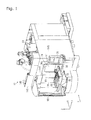
- FIGs. 1 to 9 A vertical machining center according to an embodiment of the present invention will be described below by referring to FIGs. 1 to 9 .
- the right and left as viewed facing a front F of a vertical machining center 10 are respectively intended as the right and left of the vertical machining center 10.
- the front side of the vertical machining center 10 is intended as "front”
- the rear side of the vertical machining center 10 is intended as "rear”.
- the vertical machining center 10 includes splash guards 14A and 14B, which surround the front, right, and left sides of the machine.
- a front area of the surrounded space of the machine is a machining area 12, as shown in FIG. 5 .
- the vertical machining center 10 includes a saddle 18 and a machining table 20.
- the saddle 18 moves on a Y axis track 17, which is disposed on a bed 16, in a Y axis direction, which is a front-rear machine direction.
- the machining table 20 moves on an X axis track 19, which is disposed on the saddle 18, in an X axis direction, which is a right-left machine direction.
- the machining table 20 moves in the X axis direction and the Y axis direction respectively by an X-axis drive motor and a Y-axis drive motor, not shown.
- a pallet 60 bearing a workpiece is to be placed.
- a column 22 On the bed 16, a column 22 is disposed.
- the column 22 is integral with the bed 16.
- a Z axis track 24 is disposed.
- a spindle head 28 On the Z axis track 24, a spindle head 28 is disposed.
- the spindle head 28 moves in a Z axis direction, which is an upward-downward direction, and has a spindle, not shown.
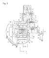
- O indicates an axial center of the spindle
- n indicates a line parallel to a Y axis passing through the axial center O of the spindle and will be hereinafter referred to as "spindle base line n".
- the machining table 20 has a pallet exchange position that is offset in the X axis direction from the axial center O of the spindle by a predetermined amount R of offset.
- the predetermined amount R of offset is half the width of the pallet 60. It is noted that the width of the pallet 60 is the right-left direction length, that is, the X-axis direction length, of the pallet 60 in FIG. 2 . It is also noted that the amount R of offset will not be limited to a value that is half the width of the pallet. Still, the amount R of offset is preferably equivalent to a length that is equal to or less than half the above-described width. In excess of the half value of the width, although the length in the right-left direction of the operator area including a cutout area 80, described later, increases, the machine width of the vertical machining center increases.
- a clamp device 31 is disposed on the machining table 20.
- the clamp device 31 includes a cylinder 32, a circular-arc clamp plate 34, and a positioning pin 29.
- the cylinder 32 is disposed on the machining table 20.
- the clamp plate 34 is lifted upward and downward by a piston rod 33 of the cylinder 32.
- the positioning pin 29 accurately positions the pallet 60 when the pallet 60 is clamped onto the machining table 20.
- the clamp plate 34 has four rolling rollers 41 on the inner circumferential side of the upper surface of the circular arc shape of the clamp plate 34, and also has four rolling rollers 41 on the outer circumferential side of the upper surface of the circular arc shape of the clamp plate 34.
- Each of the rolling rollers 41 is buried in the upper surface with the rolling surface exposed, and the clamp plate 34 is freely fitted and rollable in an engagement groove 62, which is elongate in a circular-arc shape in the width direction on the lower surface of the pallet 60. Then, when the piston rod 33 of the cylinder 32 moves downward, the clamp plate 34 and the machining table 20 hold between them a pair of protruded rims 63, thereby clamping the pallet 60 onto the machining table 20.
- the pair of protruded rims 63 are opposed to one another and protrude from lower portions of the inner circumferential side and the outer circumferential side of the engagement groove 62 of the pallet 60. It is noted that the positioning pin 29 is fitted into a predetermined engagement hole (not shown) of the pallet 60 immediately before the pallet 60 is clamped. When the piston rod 33 moves upward, the pallet 60 is unclamped.
- the circular-arc clamp plate 34 and guide members 54 of a setup table 52 are on the same circumference.
- the clamp plate 34 is lifted upward in conjunction with the upward movement of the piston rod 33 of the cylinder 32. This makes the upper surfaces of the rollers 41 on the clamp plate 34 flush with the upper surfaces of rollers 65, described later, of the guide members 54 on the setup table 52, enabling the pallet 60 to make a rotational movement.
- rollers have been exemplified as the guide mechanism
- the guide mechanism may not necessarily be cylindrical rollers; a spherical shape is also possible. It is also possible to use a sliding contact member insofar as the clamp plate 34 movably supports the ceiling surface of the engagement groove 62, which is on the lower surface of the pallet 60.
- an opening 30 is formed on the splash guard 14A, which is a front wall, that is, a forward-side wall, of the vertical machining center 10.
- the opening 30 has a lower portion that is at or higher than the height of the waist of a person, and as a whole, the opening 30 has an approximately square shape.
- a partition door 36 is supported in a slidable manner in the upward-downward directions to partition the machining area 12 and a setup area 42 from one another.
- a solenoid valve capable of three-way positioning, namely, open position, closed position, and intermediate position is used.
- the solenoid valve is given an open command and takes its open position, the partition door 36 is driven by a piston rod 39 of a pneumatic or hydraulic cylinder 35 as shown in FIG. 4 and moved into open position, where the opening 30 is opened.
- the partition door 36 When the solenoid valve is given a close command and takes its closed position, the partition door 36 is driven by the piston rod 39 of the pneumatic or hydraulic cylinder 35 shown in FIG. 4 and moved into closed position, where the opening 30 is closed. It is noted that when the partition door 36 is at its open position or closed position, a pair of position detection switches, not shown, are in activation to output an open state signal or a closed state signal to a controller, not shown.
- partition door 36 has been illustrated as being slidable in the upward-downward directions, the partition door 36 may be slidable in a right-left direction.
- the partition door 36 may also be wound up.
- the partition door 36 is provided with a window 38 through which the machining area 12 is viewable.
- the window 38 is fitted with a transparent plate 37.
- the window 38 is disposed in an area on the partition door 36 that makes the machining area 12 viewable, that is, an area that enables the operator to see the spindle machining a workpiece, when the operator has access to the cutout area 80, described later, which is the operator area.
- the window 38 is disposed on an area of the partition door 36 that is at the right side relative to a cover 45. It is noted that the window 38 may be disposed approximately over the entire area on the partition door 36.
- the operator area is an area to which the operator is accessible, that is, an area that the operator can enter, and the operator area includes the cutout area 80 when an openable-closable cover 90, described later, is open.
- the setup area 42 is disposed at a position further forward than the front of the vertical machining center 10. As shown in FIGs. 2 and 5 , the setup area 42 is an area of space defined by a cover wall 89, described later, the openable-closable cover 90 in closed state, and the partition door 36 at its closed position.
- the setup area 42 is an area of space where the operator or some other person performs a setup operation.
- the setup area 42 communicates with the machining area 12 through the opening 30. As shown in FIG. 5 , in the setup area 42, the setup table 52 is supported by a lower support member 23 at a position that has a 180-degree phase difference from the machining table 20 at the pallet exchange position.
- an oil pan 70 is supported by the lower support member 23.
- the oil pan 70 accommodates at least a part of a pallet rotational movement area located outside the splash guard 14A on the machine front.
- the front area of the oil pan 70 is larger than the setup table 52, and the oil pan 70 covers a lower part of the setup table 52. This ensures that the oil pan 70 collects chips and attached cutting fluid resulting from cutting when they drop from the pallet 60 or the workpiece during rotation associated with pallet exchange or after completion of the pallet exchange. It is noted that for the convenience of illustration, the oil pan 70 is not shown in FIG. 9 .
- the oil pan 70 has a cutout portion 72.
- the cutout portion 72 is formed by cutting one end of the oil pan 70 that is closer in the X axis direction to the axial center of the spindle, that is, closer to the spindle base line n (which is a line parallel to the Y axis passing through the axial center of the spindle) than the other end of the oil pan 70 is to the spindle base line n.
- the cutout portion 72 is formed by cutting the one end of the oil pan 70 closer to the spindle base line n on a line parallel to the spindle base line n.
- the cutout area 80 is formed and exposed to the cutout portion 72 and the splash guard 14A.
- the cutout area 80 serves as an area of space through which the operator has access to the spindle, the workpiece placed on the pallet at the machining area side, and the pallet at the setup area 42 side.
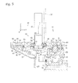
- the pallet exchanger 40 is a rotary device that includes a rotary drive unit 43 and a guide mechanism 44 disposed at the setup area 42 side.
- the rotary drive unit 43 is disposed at a lower portion of the opening 30, which is a boundary area between the setup area 42 and the machining area 12. As shown in FIG. 2 , the rotary drive unit 43 has its rotational center located at a position through which a center line L in the width direction of the pallet 60 passes when the machining table 20 is positioned at the pallet exchange position.
- the rotary drive unit 43 includes a drive motor 46, a reduction device 48, and a pair of hooks 50.
- the reduction device 48 includes a rotary output device 49 on the outermost circumference of the rotary drive unit 43 to serve as an output device, and is coupled to the drive motor 46.
- the pair of hooks 50 are disposed at 180-degree opposed positions on the rotary output device 49.
- the reduction device 48 is disposed on a securing member 47 of the lower support member 23, which is mounted to the bed 16.
- the drive motor 46 is covered by a cover 45.
- the cover 45 is fixed by an upper support member, not shown, of the vertical machining center 10.
- the rotational center m of the pallet exchanger 40 is the axial center of the output axis of the drive motor 46. It is noted that the rotational center m may not necessarily be limited to the axial center of the output axis of the drive motor 46.
- the rotational center may also be the axial center of a gear that constitutes a gear mechanism driven by the drive motor.
- hook 50 is an engagement claw
- engagement claw is not intended in a limiting sense.
- Other examples include an engagement pin.
- the clamp plate 34 is lifted upward to push the pallet 60 upward and bring a pair of hooks 64, which are disposed on one side of the pallet 60, into engagement with the hook 50, enabling the pallet 60 to make a rotational movement.
- the pallet 60 in the machining area 12 is clamped, the pallet 60 is lifted downward together with the clamp plate 34. This brings the pair of hooks 64, which are disposed on one side of the pallet 60, out of engagement with the hook 50.
- the guide mechanism 44 guides the pallet 60 when the pallet 60 is moved during pallet exchange.
- the guide mechanism 44 includes the guide members 54 and the rolling rollers 65.
- the guide members 54 are mounted on a circular arc member 53, which is disposed on the outer circumference of the setup table 52.
- the rollers 65 are mounted on the respective guide members 54. As shown in FIG. 3 , the center of the circular arc of the circular arc member 53 is the rotational center m of the pallet exchanger 40.
- the plurality of guide members 54 which constitute the guide mechanism 44, each have a rectangular plate shape.
- the guide members 54 are disposed on the circular arc member 53 in a radial manner relative to the rotational center m, and are fixed to respective mounting stands 55 shown in FIG. 5 at intervals.
- the mounting stands 55 are disposed on the circular arc member 53.
- the guide members 54 each have the same thickness as the thickness of the clamp plate 34, and are freely fitted in the engagement groove 62 of the pallet 60 around the rotational center m.
- the rollers 65 are rotatably supported on both ends in the longitudinal direction of the guide members 54. The rollers 65 roll on the ceiling surface of the engagement groove of the pallet 60.
- the pallet 60 is rotatably supported on the upper portion of each of the rollers 65.
- the pallet 60 is also placed on the setup table 52, similarly to the case of the machining table 20.
- the height of the rollers 65 of the guide members 54 is set at the same height of the rollers 41 on the clamp plate 34 at the time when the pallet 60 in the machining area 12 is unclamped.
- the guide members 54 and the rollers 65, which constitute the guide mechanism 44, are kept off the cutout area 80.
- the guide mechanism 44 may be partially disposed in the cutout area 80 insofar as this does not interfere with the operator in entering the cutout area 80 when the openable-closable cover 90 is open.
- rollers 65 of the guide members 54 may not necessarily be cylindrical rollers; a spherical shape is also possible. It is also possible to use a sliding contact member.
- the pallets 60 are able to be exchanged along a rotational track represented by the broken line shown in the machining area 12, the setup area 42, and the cutout area 80 in FIGs. 2 , 3 , and 6 .
- the track is drawn by a corner of the pallet 60 that is farthest from the rotational center m.
- the area defined by the broken line is the pallet rotational movement area.
- the cover wall 89 extends to the front of the vertical machining center 10 from the left splash guard 14B.
- the cover wall 89 is a left outer wall of the setup area 42.
- the openable-closable cover 90 is supported in a manually operable manner to open and close the front and right sides of the setup area 42.
- FIG. 2 shows the openable-closable cover 90 in open state
- FIG. 6 shows the openable-closable cover 90 in closed state.
- the openable-closable cover 90 when the openable-closable cover 90 is open, the operator is accessible to the cutout area 80. As shown in FIG. 6 , when the openable-closable cover 90 is closed, the cutout area 80 is closed by the openable-closable cover 90. When the openable-closable cover 90 is closed, the operator is not accessible to the inside of the cutout area 80, and the cutout area 80 serves as a part of the pallet rotation area of the pallet exchanger.
- the openable-closable cover 90 assumes the function of collecting chips, cutting fluid, and other substances that the oil pan 70 lacks due to its cutout portion.
- the openable-closable cover 90 on its closed end, is provided with a window 92, through which the setup area 42 is viewable.
- the window 92 is fitted with a transparent plate 91. Providing the window 92 ensures that when the openable-closable cover 90 is closed, the operator is able to see the setup area 42 through the window 92 and see the machining area 12 through the window 92 and the window 38 of the partition door 36, from outside the openable-closable cover 90.
- an operation panel 76 is disposed on the right end of the splash guard 14A, which is a front wall of the vertical machining center 10.
- the operation panel 76 is supported by a bracket 77 in a rotatable manner between a rotation position where the panel surface faces the cutout area 80 as shown in FIG. 2 and a rotation position where the panel surface faces forward as shown in FIG. 6 .
- the position at which the operation panel 76 is disposed corresponds to a position adjacent the operator area including the cutout area 80. It is noted that the position at which the operation panel 76 is disposed will not be limited to the right end of the splash guard 14A, which is a front wall of the vertical machining center 10.
- the operation panel 76 includes, on its panel surface, a monitor, operation keys, and other keys used to input into a controller, not shown, various operation commands for the vertical machining center 10.
- the pallet 60 In the machining area 12, as the machining table 20 moves in the X axis direction or the Y axis direction, the pallet 60 also moves in the same direction while being clamped on the machining table 20 by the clamp device 31 and carrying a workpiece, not shown. The workpiece on the machining table 20 in the machining area 12 undergoes cutting by a cutting tool, not shown, mounted on the spindle.
- an un-machined workpiece is placed on the pallet 60 in the setup area 42. While the workpiece is undergoing cutting, the opening 30 is closed by the partition door 36 that is being at its closed position. In this case, the operator may enter the cutout area 80 with the openable-closable cover 90 in open state so as to see the machining area 12 through the window 38. Also as shown in FIG. 2 , with the operation panel 76 being at the rotation position to face the cutout area 80, or with the operation panel 76 being at the rotation position to face forward, the operator may input from the operation panel 76 various operation commands into the controller, not shown.
- the openable-closable cover 90 is closed as shown in FIG. 6 , and thus the operator is prevented from entering the cutout area 80.
- the controller When pallet exchange is executed after the cutting of the workpiece has ended, the controller, not shown, moves the machining table 20 to the pallet exchange position shown in FIG. 2 .
- the controller also gives an open command to the solenoid valve, not shown, so as to move the partition door 36 to the open position.
- the controller lifts upward the piston rod 33 of the clamp device 31 shown in FIG. 5 , thereby releasing the pallet 60 fixed to the machining table 20 by the clamp plate 34.
- the clamp device 31 unclamps the pallet 60 so as to cause the clamp plate 34 to push the pallet 60 upward and bring the hooks 64 of the pallet 60 into engagement with the hook 50 of the rotary drive unit 43 positioned at the machining area 12 side.
- the controller not shown, confirms that the partition door 36 is open using a position detection switch, not shown, of the partition door 36. Then, the controller, not shown, drives the drive motor 46. Driving the drive motor 46 brings the pallets 60 in the machining area 12 and the setup area 42 into 180-degree rotation about the rotational center m. Examples of the direction of the rotation include the clockwise direction and the anti-clockwise direction.
- the controller After both pallets 60 have been brought into 180-degree rotation and exchanged, the controller, not shown, clamps the pallet 60 onto the machining table 20. Specifically, the piston rod 33 of the clamp device 31 shown in FIG. 5 is lifted downward. This causes the pallet 60 in the machining area 12 to be lifted downward and brings the hooks 64 out of engagement with the hook 50. Then, the pallet 60 is fixed to the machining table 20 by the clamp plate 34.
- the controller also gives a close command to the solenoid valve, not shown, so as to move the partition door 36 to the closed position.
- the controller confirms that the partition door 36 is closed using the position detection switch, not shown, of the partition door 36. Then, the controller, not shown, moves the machining table 20 from the pallet exchange position to the vicinity of the spindle, and subjects the workpiece on the pallet 60 to cutting.
- the operator brings the openable-closable cover 90 into open state, and then enters the cutout area 80 to perform a setup operation such as exchanging the machined workpiece on the pallet 60 in the setup area 42 with an un-machined workpiece next to be treated.
- the vertical machining center 10 includes the partition door 36, which partitions the machining area 12 and the setup area 42 from one another in an openable and closable manner, and the openable-closable cover 90, which opens and closes the setup area 42.
- the cutout portion 72 is disposed at one end of the oil pan 70.
- the area of space exposed to the cutout portion 72 serves as a part of the operator area, to which the operator is accessible, when the openable-closable cover 90 is open, that is, when the area is in open state.
- the openable-closable cover 90 is closed, that is, when the area of space exposed to the cutout portion 72 is in closed state, the area serves as a part of the pallet rotation area of the pallet exchanger 40. This, as a result, prevents an increase in the machine width while ensuring the operator area in front of the machine and ensuring operations including handling the tool mounted on the spindle in the operator area.
- the rotational center m of the pallet exchanger 40 is offset in the X axis direction from the axial center O of the spindle of the spindle head 28.
- the one end of the oil pan 70 at which the cutout portion 72 is disposed is closer in the X axis direction to the axial center of the spindle, that is, closer to the spindle base line n than the other end of the cutout portion 72 is to the spindle base line n.
- the rotational center of the pallet exchanger 40 is offset in the X axis direction from the axial center O of the spindle. This, as a result, shortens the distance between the cutout area and the spindle, and further facilitates operations including handling the tool mounted on the spindle in the operator area including the cutout area.
- the window 38 is disposed at least on the cutout area 80 side of the partition door 36. Through the window 38, the machining area 12 is viewable. This, as a result, enables the operator to observe the machining area 12 through the window 38 during automatic operation.
- the amount R of offset in the X axis direction from the axial center O of the spindle of the spindle head 28 to the rotational center m of the pallet exchanger 40 is equal to or less than half the width of the pallet.
- the pallet exchanger 40 includes the guide mechanism 44, which guides the pallet 60 during pallet exchange.
- the guide mechanism 44 is disposed at a position other than the cutout area 80. This, as a result, ensures that the cutout area serves as a part of the operator area even in a pallet exchanger provided with a guide mechanism.
- the operation panel 76 is disposed at a position adjacent the cutout area 80.
- the operation panel 76 is rotatable at least into a rotation position where the operation panel 76 faces the cutout area 80.
- This configuration ensures that when the operator is adjacent the cutout area 80, the operator may position the operation panel 76 at the rotation position where the operation panel 76 faces the cutout area 80, thereby facilitating handling of the operation panel. That is, the operation panel can be oriented in a more suitable direction in accordance with whether the operation is intended for the machine itself or the setup area. This, as a result, ensures use of the same operation panel for the operations associated with the machine itself, pallet exchange, and setup and exchange, thus keeping the cost low.
- the rotational center m of the pallet exchanger 40 is offset to the left side from the axial center O of the spindle, and the cutout portion 72 of the oil pan 70 is disposed on the right end of the oil pan 70.
- the offset direction may be to the right side, which is opposite the left side.
- the cutout portion is disposed on the left end of the oil pan 70.
Landscapes
- Engineering & Computer Science (AREA)
- Mechanical Engineering (AREA)
- Auxiliary Devices For Machine Tools (AREA)
- Feeding Of Workpieces (AREA)
Applications Claiming Priority (1)
| Application Number | Priority Date | Filing Date | Title |
|---|---|---|---|
| PCT/JP2012/070547 WO2014024319A1 (ja) | 2012-08-10 | 2012-08-10 | 立型マシニングセンタ |
Publications (3)
| Publication Number | Publication Date |
|---|---|
| EP2801439A1 true EP2801439A1 (de) | 2014-11-12 |
| EP2801439A4 EP2801439A4 (de) | 2015-04-22 |
| EP2801439B1 EP2801439B1 (de) | 2016-04-20 |
Family
ID=50067599
Family Applications (1)
| Application Number | Title | Priority Date | Filing Date |
|---|---|---|---|
| EP12882722.7A Active EP2801439B1 (de) | 2012-08-10 | 2012-08-10 | Vertikales bearbeitungszentrum |
Country Status (5)
| Country | Link |
|---|---|
| US (1) | US9073157B2 (de) |
| EP (1) | EP2801439B1 (de) |
| JP (1) | JP5497972B1 (de) |
| CN (1) | CN104994991B (de) |
| WO (1) | WO2014024319A1 (de) |
Families Citing this family (16)
| Publication number | Priority date | Publication date | Assignee | Title |
|---|---|---|---|---|
| JP6165550B2 (ja) * | 2013-08-19 | 2017-07-19 | Dmg森精機株式会社 | 工作機械及び該工作機械を複数備えた加工ライン |
| JP6113673B2 (ja) * | 2014-02-06 | 2017-04-12 | 株式会社オーエム製作所 | 工作機械 |
| CN105451935B (zh) * | 2014-05-22 | 2017-02-08 | 山崎马扎克公司 | 机床 |
| US20160246490A1 (en) * | 2015-02-25 | 2016-08-25 | Bank Of America Corporation | Customizable Dashboard |
| KR101838999B1 (ko) | 2015-10-20 | 2018-03-15 | 일신에프에이 주식회사 | 인덱스머신의 도어 어셈블리 및 이를 포함하는 인덱스머신 |
| USD873876S1 (en) * | 2017-06-21 | 2020-01-28 | Cama1 S.P.A. | Packaging machine |
| US11305388B2 (en) | 2017-09-13 | 2022-04-19 | Makino Milling Machine Co., Ltd. | Machine tool |
| CN107671131A (zh) * | 2017-10-09 | 2018-02-09 | 邯郸新兴特种管材有限公司 | 一种超长钢管拔制装置 |
| KR102049546B1 (ko) * | 2018-06-29 | 2019-11-27 | 주식회사에이비프로바이오 | 회전형 분리벽을 갖는 머시닝 센터 |
| USD866622S1 (en) * | 2018-07-12 | 2019-11-12 | Doosan Machine Tools Co., Ltd. | Machine center |
| CN108747440A (zh) * | 2018-08-31 | 2018-11-06 | 无锡金戈数控设备有限公司 | 多功能数控加工中心 |
| AT523476B1 (de) * | 2020-01-27 | 2021-10-15 | Trumpf Werkzeugmaschinen Gmbh Co Kg | Bearbeitungsvorrichtung zum Bearbeiten eines oder mehrerer Werkstücke |
| JP7727269B2 (ja) * | 2021-11-30 | 2025-08-21 | ブラザー工業株式会社 | 制御装置及び制御方法 |
| USD1112381S1 (en) * | 2022-05-17 | 2026-02-10 | Haas Schleifmaschinen Gmbh | Machine tool |
| JP1759785S (ja) * | 2023-02-20 | 2023-12-19 | マシニングセンタ | |
| WO2025115072A1 (ja) * | 2023-11-27 | 2025-06-05 | ヤマザキマザック株式会社 | 工作機械、および、ワーク加工方法 |
Family Cites Families (19)
| Publication number | Priority date | Publication date | Assignee | Title |
|---|---|---|---|---|
| JPS58109247A (ja) * | 1981-12-19 | 1983-06-29 | Hitachi Seiki Co Ltd | ロータリー型パレット交換装置の移動カバー装置 |
| US4673076B1 (en) * | 1984-09-04 | 2000-02-01 | Kearney & Trecker Corp | Rotary shuttle for machine tools |
| CN85106747A (zh) * | 1985-09-05 | 1987-03-25 | 卡尼特雷克公司 | 机床的旋转往复送件机构 |
| JPH02185341A (ja) * | 1989-01-10 | 1990-07-19 | Mitsubishi Heavy Ind Ltd | パレット交換装置付き工作機械 |
| JP2548646Y2 (ja) | 1991-12-26 | 1997-09-24 | 日立精機株式会社 | 工作機械のパレット交換装置 |
| JP2927100B2 (ja) * | 1992-04-23 | 1999-07-28 | ブラザー工業株式会社 | 工作機械 |
| JPH0627028U (ja) * | 1992-09-08 | 1994-04-12 | 大阪機工株式会社 | 工作機械の操作盤装置 |
| US5265497A (en) * | 1992-09-08 | 1993-11-30 | Cincinnati Milacron Inc. | Guard for operator access station |
| US5622247A (en) * | 1994-11-16 | 1997-04-22 | Kitamura Machinery Co., Ltd. | Pallet changer |
| US6082939A (en) * | 1998-07-09 | 2000-07-04 | Toyoda Koki Kabushiki Kaisha | Machine tool and cover apparatus therefor |
| JP2001170839A (ja) | 1999-12-17 | 2001-06-26 | Aska Trading Kk | パレット交換装置 |
| JP4502155B2 (ja) * | 2000-02-22 | 2010-07-14 | 森精機興産株式会社 | 工作機械のパレット交換装置 |
| DE10020804A1 (de) * | 2000-04-28 | 2001-11-08 | Deckel Maho Geretsried Gmbh | Schutzabdeckung für eine Werkzeugmaschine |
| DE50200017D1 (de) * | 2002-03-02 | 2003-08-07 | Hermle Berthold Maschf Ag | Werkstückträger-Wechseleinrichtung für Werkzeugmaschinen |
| JP3984097B2 (ja) * | 2002-05-17 | 2007-09-26 | オークマ株式会社 | パレット交換装置 |
| JP2007152506A (ja) * | 2005-12-06 | 2007-06-21 | Mitsui Seiki Kogyo Co Ltd | 立型マシニングセンタにおけるパレットチェンジャとオペレータの配置構造 |
| DE102008048571A1 (de) * | 2008-09-23 | 2010-03-25 | Grob-Werke Gmbh & Co. Kg | Bearbeitungseinheit |
| KR20110032020A (ko) * | 2009-09-22 | 2011-03-30 | 두산인프라코어 주식회사 | 수평형 머시닝 센터의 팰리트 전달장치 |
| CN201613483U (zh) * | 2009-12-10 | 2010-10-27 | 沈阳机床(集团)设计研究院有限公司 | 一种可重新配置的立式加工中心机床 |
-
2012
- 2012-08-10 JP JP2013553182A patent/JP5497972B1/ja active Active
- 2012-08-10 CN CN201280027053.1A patent/CN104994991B/zh active Active
- 2012-08-10 EP EP12882722.7A patent/EP2801439B1/de active Active
- 2012-08-10 WO PCT/JP2012/070547 patent/WO2014024319A1/ja not_active Ceased
-
2014
- 2014-09-23 US US14/494,184 patent/US9073157B2/en active Active
Also Published As
| Publication number | Publication date |
|---|---|
| EP2801439A4 (de) | 2015-04-22 |
| EP2801439B1 (de) | 2016-04-20 |
| WO2014024319A1 (ja) | 2014-02-13 |
| US20150016914A1 (en) | 2015-01-15 |
| CN104994991B (zh) | 2016-06-29 |
| JP5497972B1 (ja) | 2014-05-21 |
| CN104994991A (zh) | 2015-10-21 |
| JPWO2014024319A1 (ja) | 2016-07-21 |
| US9073157B2 (en) | 2015-07-07 |
Similar Documents
| Publication | Publication Date | Title |
|---|---|---|
| EP2801439B1 (de) | Vertikales bearbeitungszentrum | |
| US7255519B2 (en) | Machine tool | |
| CN210451004U (zh) | 一种全自动车削双面的数控车床 | |
| EP3511117B1 (de) | Werkzeugmaschine | |
| JP3054392B2 (ja) | 金属成形プレスのための工具交換機構並びに金属成形プレス及び工具交換機構を含むシステム | |
| US9126298B2 (en) | Machining center | |
| US20150298272A1 (en) | Machine tool | |
| US10940548B2 (en) | Machine for machining workpieces | |
| MXPA02000494A (es) | Accesorio montable en un munon. | |
| KR102324412B1 (ko) | 터렛 공구대 및 이를 갖는 공작 기계 | |
| KR20160006173A (ko) | 팔레트 체인저를 구비하는 머신 툴 | |
| JP2008149416A (ja) | マシニングセンタ | |
| US5099980A (en) | Pallet exchanger for machine tools | |
| JPH0647219B2 (ja) | パレット交換装置 | |
| US8573908B2 (en) | Machining center including a control board arranged side by side with an operator door | |
| US4164809A (en) | Machine tool with automatic tool change apparatus | |
| JP3985998B2 (ja) | 複合加工用工作機械 | |
| JP2010228068A (ja) | 工作機械システムの機種切替方法及び装置 | |
| KR20160079183A (ko) | 자동 팔레트 교환 장치 | |
| JP2006110659A (ja) | 工作機械 | |
| CN112318211A (zh) | 一种紧凑型带多工位不停机换料功能的卧式加工中心 | |
| JP2008296294A (ja) | パレット交換装置 | |
| JP2007152506A (ja) | 立型マシニングセンタにおけるパレットチェンジャとオペレータの配置構造 | |
| CN211135671U (zh) | 多功能铣床 | |
| KR200485075Y1 (ko) | 강판 코일 로딩용 지그 |
Legal Events
| Date | Code | Title | Description |
|---|---|---|---|
| PUAI | Public reference made under article 153(3) epc to a published international application that has entered the european phase |
Free format text: ORIGINAL CODE: 0009012 |
|
| 17P | Request for examination filed |
Effective date: 20140806 |
|
| AK | Designated contracting states |
Kind code of ref document: A1 Designated state(s): AL AT BE BG CH CY CZ DE DK EE ES FI FR GB GR HR HU IE IS IT LI LT LU LV MC MK MT NL NO PL PT RO RS SE SI SK SM TR |
|
| RA4 | Supplementary search report drawn up and despatched (corrected) |
Effective date: 20150324 |
|
| RIC1 | Information provided on ipc code assigned before grant |
Ipc: B23Q 11/08 20060101ALI20150318BHEP Ipc: B23Q 7/14 20060101ALI20150318BHEP Ipc: B23Q 7/00 20060101AFI20150318BHEP Ipc: B23Q 1/66 20060101ALI20150318BHEP |
|
| DAX | Request for extension of the european patent (deleted) | ||
| GRAP | Despatch of communication of intention to grant a patent |
Free format text: ORIGINAL CODE: EPIDOSNIGR1 |
|
| INTG | Intention to grant announced |
Effective date: 20151204 |
|
| GRAS | Grant fee paid |
Free format text: ORIGINAL CODE: EPIDOSNIGR3 |
|
| GRAA | (expected) grant |
Free format text: ORIGINAL CODE: 0009210 |
|
| AK | Designated contracting states |
Kind code of ref document: B1 Designated state(s): AL AT BE BG CH CY CZ DE DK EE ES FI FR GB GR HR HU IE IS IT LI LT LU LV MC MK MT NL NO PL PT RO RS SE SI SK SM TR |
|
| REG | Reference to a national code |
Ref country code: GB Ref legal event code: FG4D |
|
| REG | Reference to a national code |
Ref country code: CH Ref legal event code: EP |
|
| REG | Reference to a national code |
Ref country code: AT Ref legal event code: REF Ref document number: 791862 Country of ref document: AT Kind code of ref document: T Effective date: 20160515 |
|
| REG | Reference to a national code |
Ref country code: IE Ref legal event code: FG4D |
|
| REG | Reference to a national code |
Ref country code: DE Ref legal event code: R096 Ref document number: 602012017502 Country of ref document: DE |
|
| REG | Reference to a national code |
Ref country code: FR Ref legal event code: PLFP Year of fee payment: 5 |
|
| REG | Reference to a national code |
Ref country code: LT Ref legal event code: MG4D |
|
| REG | Reference to a national code |
Ref country code: AT Ref legal event code: MK05 Ref document number: 791862 Country of ref document: AT Kind code of ref document: T Effective date: 20160420 |
|
| REG | Reference to a national code |
Ref country code: NL Ref legal event code: MP Effective date: 20160420 |
|
| PG25 | Lapsed in a contracting state [announced via postgrant information from national office to epo] |
Ref country code: NL Free format text: LAPSE BECAUSE OF FAILURE TO SUBMIT A TRANSLATION OF THE DESCRIPTION OR TO PAY THE FEE WITHIN THE PRESCRIBED TIME-LIMIT Effective date: 20160420 Ref country code: NO Free format text: LAPSE BECAUSE OF FAILURE TO SUBMIT A TRANSLATION OF THE DESCRIPTION OR TO PAY THE FEE WITHIN THE PRESCRIBED TIME-LIMIT Effective date: 20160720 Ref country code: LT Free format text: LAPSE BECAUSE OF FAILURE TO SUBMIT A TRANSLATION OF THE DESCRIPTION OR TO PAY THE FEE WITHIN THE PRESCRIBED TIME-LIMIT Effective date: 20160420 Ref country code: FI Free format text: LAPSE BECAUSE OF FAILURE TO SUBMIT A TRANSLATION OF THE DESCRIPTION OR TO PAY THE FEE WITHIN THE PRESCRIBED TIME-LIMIT Effective date: 20160420 Ref country code: PL Free format text: LAPSE BECAUSE OF FAILURE TO SUBMIT A TRANSLATION OF THE DESCRIPTION OR TO PAY THE FEE WITHIN THE PRESCRIBED TIME-LIMIT Effective date: 20160420 |
|
| PG25 | Lapsed in a contracting state [announced via postgrant information from national office to epo] |
Ref country code: RS Free format text: LAPSE BECAUSE OF FAILURE TO SUBMIT A TRANSLATION OF THE DESCRIPTION OR TO PAY THE FEE WITHIN THE PRESCRIBED TIME-LIMIT Effective date: 20160420 Ref country code: GR Free format text: LAPSE BECAUSE OF FAILURE TO SUBMIT A TRANSLATION OF THE DESCRIPTION OR TO PAY THE FEE WITHIN THE PRESCRIBED TIME-LIMIT Effective date: 20160721 Ref country code: LV Free format text: LAPSE BECAUSE OF FAILURE TO SUBMIT A TRANSLATION OF THE DESCRIPTION OR TO PAY THE FEE WITHIN THE PRESCRIBED TIME-LIMIT Effective date: 20160420 Ref country code: HR Free format text: LAPSE BECAUSE OF FAILURE TO SUBMIT A TRANSLATION OF THE DESCRIPTION OR TO PAY THE FEE WITHIN THE PRESCRIBED TIME-LIMIT Effective date: 20160420 Ref country code: AT Free format text: LAPSE BECAUSE OF FAILURE TO SUBMIT A TRANSLATION OF THE DESCRIPTION OR TO PAY THE FEE WITHIN THE PRESCRIBED TIME-LIMIT Effective date: 20160420 Ref country code: ES Free format text: LAPSE BECAUSE OF FAILURE TO SUBMIT A TRANSLATION OF THE DESCRIPTION OR TO PAY THE FEE WITHIN THE PRESCRIBED TIME-LIMIT Effective date: 20160420 Ref country code: SE Free format text: LAPSE BECAUSE OF FAILURE TO SUBMIT A TRANSLATION OF THE DESCRIPTION OR TO PAY THE FEE WITHIN THE PRESCRIBED TIME-LIMIT Effective date: 20160420 Ref country code: PT Free format text: LAPSE BECAUSE OF FAILURE TO SUBMIT A TRANSLATION OF THE DESCRIPTION OR TO PAY THE FEE WITHIN THE PRESCRIBED TIME-LIMIT Effective date: 20160822 |
|
| PG25 | Lapsed in a contracting state [announced via postgrant information from national office to epo] |
Ref country code: BE Free format text: LAPSE BECAUSE OF FAILURE TO SUBMIT A TRANSLATION OF THE DESCRIPTION OR TO PAY THE FEE WITHIN THE PRESCRIBED TIME-LIMIT Effective date: 20160420 |
|
| REG | Reference to a national code |
Ref country code: DE Ref legal event code: R097 Ref document number: 602012017502 Country of ref document: DE |
|
| PG25 | Lapsed in a contracting state [announced via postgrant information from national office to epo] |
Ref country code: EE Free format text: LAPSE BECAUSE OF FAILURE TO SUBMIT A TRANSLATION OF THE DESCRIPTION OR TO PAY THE FEE WITHIN THE PRESCRIBED TIME-LIMIT Effective date: 20160420 Ref country code: DK Free format text: LAPSE BECAUSE OF FAILURE TO SUBMIT A TRANSLATION OF THE DESCRIPTION OR TO PAY THE FEE WITHIN THE PRESCRIBED TIME-LIMIT Effective date: 20160420 Ref country code: RO Free format text: LAPSE BECAUSE OF FAILURE TO SUBMIT A TRANSLATION OF THE DESCRIPTION OR TO PAY THE FEE WITHIN THE PRESCRIBED TIME-LIMIT Effective date: 20160420 Ref country code: SK Free format text: LAPSE BECAUSE OF FAILURE TO SUBMIT A TRANSLATION OF THE DESCRIPTION OR TO PAY THE FEE WITHIN THE PRESCRIBED TIME-LIMIT Effective date: 20160420 Ref country code: CZ Free format text: LAPSE BECAUSE OF FAILURE TO SUBMIT A TRANSLATION OF THE DESCRIPTION OR TO PAY THE FEE WITHIN THE PRESCRIBED TIME-LIMIT Effective date: 20160420 |
|
| PLBE | No opposition filed within time limit |
Free format text: ORIGINAL CODE: 0009261 |
|
| STAA | Information on the status of an ep patent application or granted ep patent |
Free format text: STATUS: NO OPPOSITION FILED WITHIN TIME LIMIT |
|
| PG25 | Lapsed in a contracting state [announced via postgrant information from national office to epo] |
Ref country code: SM Free format text: LAPSE BECAUSE OF FAILURE TO SUBMIT A TRANSLATION OF THE DESCRIPTION OR TO PAY THE FEE WITHIN THE PRESCRIBED TIME-LIMIT Effective date: 20160420 |
|
| 26N | No opposition filed |
Effective date: 20170123 |
|
| PG25 | Lapsed in a contracting state [announced via postgrant information from national office to epo] |
Ref country code: MC Free format text: LAPSE BECAUSE OF FAILURE TO SUBMIT A TRANSLATION OF THE DESCRIPTION OR TO PAY THE FEE WITHIN THE PRESCRIBED TIME-LIMIT Effective date: 20160420 |
|
| REG | Reference to a national code |
Ref country code: CH Ref legal event code: PL |
|
| PG25 | Lapsed in a contracting state [announced via postgrant information from national office to epo] |
Ref country code: CH Free format text: LAPSE BECAUSE OF NON-PAYMENT OF DUE FEES Effective date: 20160831 Ref country code: LI Free format text: LAPSE BECAUSE OF NON-PAYMENT OF DUE FEES Effective date: 20160831 |
|
| PG25 | Lapsed in a contracting state [announced via postgrant information from national office to epo] |
Ref country code: SI Free format text: LAPSE BECAUSE OF FAILURE TO SUBMIT A TRANSLATION OF THE DESCRIPTION OR TO PAY THE FEE WITHIN THE PRESCRIBED TIME-LIMIT Effective date: 20160420 |
|
| REG | Reference to a national code |
Ref country code: IE Ref legal event code: MM4A |
|
| REG | Reference to a national code |
Ref country code: FR Ref legal event code: PLFP Year of fee payment: 6 |
|
| PG25 | Lapsed in a contracting state [announced via postgrant information from national office to epo] |
Ref country code: IE Free format text: LAPSE BECAUSE OF NON-PAYMENT OF DUE FEES Effective date: 20160810 |
|
| PG25 | Lapsed in a contracting state [announced via postgrant information from national office to epo] |
Ref country code: LU Free format text: LAPSE BECAUSE OF NON-PAYMENT OF DUE FEES Effective date: 20160810 |
|
| PG25 | Lapsed in a contracting state [announced via postgrant information from national office to epo] |
Ref country code: HU Free format text: LAPSE BECAUSE OF FAILURE TO SUBMIT A TRANSLATION OF THE DESCRIPTION OR TO PAY THE FEE WITHIN THE PRESCRIBED TIME-LIMIT; INVALID AB INITIO Effective date: 20120810 |
|
| PG25 | Lapsed in a contracting state [announced via postgrant information from national office to epo] |
Ref country code: MT Free format text: LAPSE BECAUSE OF NON-PAYMENT OF DUE FEES Effective date: 20160831 Ref country code: IS Free format text: LAPSE BECAUSE OF FAILURE TO SUBMIT A TRANSLATION OF THE DESCRIPTION OR TO PAY THE FEE WITHIN THE PRESCRIBED TIME-LIMIT Effective date: 20160420 Ref country code: MK Free format text: LAPSE BECAUSE OF FAILURE TO SUBMIT A TRANSLATION OF THE DESCRIPTION OR TO PAY THE FEE WITHIN THE PRESCRIBED TIME-LIMIT Effective date: 20160420 Ref country code: CY Free format text: LAPSE BECAUSE OF FAILURE TO SUBMIT A TRANSLATION OF THE DESCRIPTION OR TO PAY THE FEE WITHIN THE PRESCRIBED TIME-LIMIT Effective date: 20160420 |
|
| REG | Reference to a national code |
Ref country code: FR Ref legal event code: PLFP Year of fee payment: 7 |
|
| PG25 | Lapsed in a contracting state [announced via postgrant information from national office to epo] |
Ref country code: BG Free format text: LAPSE BECAUSE OF FAILURE TO SUBMIT A TRANSLATION OF THE DESCRIPTION OR TO PAY THE FEE WITHIN THE PRESCRIBED TIME-LIMIT Effective date: 20160420 |
|
| PG25 | Lapsed in a contracting state [announced via postgrant information from national office to epo] |
Ref country code: AL Free format text: LAPSE BECAUSE OF FAILURE TO SUBMIT A TRANSLATION OF THE DESCRIPTION OR TO PAY THE FEE WITHIN THE PRESCRIBED TIME-LIMIT Effective date: 20160420 Ref country code: TR Free format text: LAPSE BECAUSE OF FAILURE TO SUBMIT A TRANSLATION OF THE DESCRIPTION OR TO PAY THE FEE WITHIN THE PRESCRIBED TIME-LIMIT Effective date: 20160420 |
|
| PGFP | Annual fee paid to national office [announced via postgrant information from national office to epo] |
Ref country code: DE Payment date: 20250702 Year of fee payment: 14 |
|
| PGFP | Annual fee paid to national office [announced via postgrant information from national office to epo] |
Ref country code: IT Payment date: 20250722 Year of fee payment: 14 |
|
| PGFP | Annual fee paid to national office [announced via postgrant information from national office to epo] |
Ref country code: GB Payment date: 20250703 Year of fee payment: 14 |
|
| PGFP | Annual fee paid to national office [announced via postgrant information from national office to epo] |
Ref country code: FR Payment date: 20250703 Year of fee payment: 14 |