EP2801433A2 - Verfahren zur Herstellung von Schneidwerkzeugen - Google Patents
Verfahren zur Herstellung von Schneidwerkzeugen Download PDFInfo
- Publication number
- EP2801433A2 EP2801433A2 EP20140166372 EP14166372A EP2801433A2 EP 2801433 A2 EP2801433 A2 EP 2801433A2 EP 20140166372 EP20140166372 EP 20140166372 EP 14166372 A EP14166372 A EP 14166372A EP 2801433 A2 EP2801433 A2 EP 2801433A2
- Authority
- EP
- European Patent Office
- Prior art keywords
- base
- irradiation
- laser
- cutting edge
- high energy
- Prior art date
- Legal status (The legal status is an assumption and is not a legal conclusion. Google has not performed a legal analysis and makes no representation as to the accuracy of the status listed.)
- Withdrawn
Links
Images


Classifications
-
- B—PERFORMING OPERATIONS; TRANSPORTING
- B23—MACHINE TOOLS; METAL-WORKING NOT OTHERWISE PROVIDED FOR
- B23K—SOLDERING OR UNSOLDERING; WELDING; CLADDING OR PLATING BY SOLDERING OR WELDING; CUTTING BY APPLYING HEAT LOCALLY, e.g. FLAME CUTTING; WORKING BY LASER BEAM
- B23K31/00—Processes relevant to this subclass, specially adapted for particular articles or purposes, but not covered by any single one of main groups B23K1/00 - B23K28/00
- B23K31/02—Processes relevant to this subclass, specially adapted for particular articles or purposes, but not covered by any single one of main groups B23K1/00 - B23K28/00 relating to soldering or welding
- B23K31/025—Connecting cutting edges or the like to tools; Attaching reinforcements to workpieces, e.g. wear-resisting zones to tableware
-
- B—PERFORMING OPERATIONS; TRANSPORTING
- B23—MACHINE TOOLS; METAL-WORKING NOT OTHERWISE PROVIDED FOR
- B23K—SOLDERING OR UNSOLDERING; WELDING; CLADDING OR PLATING BY SOLDERING OR WELDING; CUTTING BY APPLYING HEAT LOCALLY, e.g. FLAME CUTTING; WORKING BY LASER BEAM
- B23K1/00—Soldering, e.g. brazing, or unsoldering
- B23K1/005—Soldering by means of radiant energy
- B23K1/0056—Soldering by means of radiant energy soldering by means of beams, e.g. lasers, electron beams [EB]
-
- B—PERFORMING OPERATIONS; TRANSPORTING
- B23—MACHINE TOOLS; METAL-WORKING NOT OTHERWISE PROVIDED FOR
- B23K—SOLDERING OR UNSOLDERING; WELDING; CLADDING OR PLATING BY SOLDERING OR WELDING; CUTTING BY APPLYING HEAT LOCALLY, e.g. FLAME CUTTING; WORKING BY LASER BEAM
- B23K26/00—Working by laser beam, e.g. welding, cutting or boring
- B23K26/20—Bonding
- B23K26/32—Bonding taking account of the properties of the material involved
-
- B—PERFORMING OPERATIONS; TRANSPORTING
- B23—MACHINE TOOLS; METAL-WORKING NOT OTHERWISE PROVIDED FOR
- B23K—SOLDERING OR UNSOLDERING; WELDING; CLADDING OR PLATING BY SOLDERING OR WELDING; CUTTING BY APPLYING HEAT LOCALLY, e.g. FLAME CUTTING; WORKING BY LASER BEAM
- B23K26/00—Working by laser beam, e.g. welding, cutting or boring
- B23K26/352—Working by laser beam, e.g. welding, cutting or boring for surface treatment
- B23K26/354—Working by laser beam, e.g. welding, cutting or boring for surface treatment by melting
-
- B—PERFORMING OPERATIONS; TRANSPORTING
- B23—MACHINE TOOLS; METAL-WORKING NOT OTHERWISE PROVIDED FOR
- B23K—SOLDERING OR UNSOLDERING; WELDING; CLADDING OR PLATING BY SOLDERING OR WELDING; CUTTING BY APPLYING HEAT LOCALLY, e.g. FLAME CUTTING; WORKING BY LASER BEAM
- B23K26/00—Working by laser beam, e.g. welding, cutting or boring
- B23K26/352—Working by laser beam, e.g. welding, cutting or boring for surface treatment
- B23K26/356—Working by laser beam, e.g. welding, cutting or boring for surface treatment by shock processing
-
- B—PERFORMING OPERATIONS; TRANSPORTING
- B23—MACHINE TOOLS; METAL-WORKING NOT OTHERWISE PROVIDED FOR
- B23K—SOLDERING OR UNSOLDERING; WELDING; CLADDING OR PLATING BY SOLDERING OR WELDING; CUTTING BY APPLYING HEAT LOCALLY, e.g. FLAME CUTTING; WORKING BY LASER BEAM
- B23K2101/00—Articles made by soldering, welding or cutting
- B23K2101/20—Tools
-
- B—PERFORMING OPERATIONS; TRANSPORTING
- B23—MACHINE TOOLS; METAL-WORKING NOT OTHERWISE PROVIDED FOR
- B23K—SOLDERING OR UNSOLDERING; WELDING; CLADDING OR PLATING BY SOLDERING OR WELDING; CUTTING BY APPLYING HEAT LOCALLY, e.g. FLAME CUTTING; WORKING BY LASER BEAM
- B23K2103/00—Materials to be soldered, welded or cut
- B23K2103/02—Iron or ferrous alloys
- B23K2103/04—Steel or steel alloys
-
- B—PERFORMING OPERATIONS; TRANSPORTING
- B23—MACHINE TOOLS; METAL-WORKING NOT OTHERWISE PROVIDED FOR
- B23K—SOLDERING OR UNSOLDERING; WELDING; CLADDING OR PLATING BY SOLDERING OR WELDING; CUTTING BY APPLYING HEAT LOCALLY, e.g. FLAME CUTTING; WORKING BY LASER BEAM
- B23K2103/00—Materials to be soldered, welded or cut
- B23K2103/16—Composite materials
Definitions
- the present invention relates to a method for manufacturing a cutting tool that is used for cutting various materials such as metal, wood, plastic, and ceramic material and is formed by joining a blade made of a hard material to a base of a steel body, and particularly, to a method for manufacturing a cutting tool in which a joint is formed by irradiation of high energy beam such as laser.
- JP 3584716 B1 a manufacturing method of disposing nickel-based metal pieces in a joint between the base and a cutting edge tip, and irradiating a high energy beam such as laser only to the base in the vicinity of the joint, thereby joining the cutting edge tip to the base in a joining layer using the nickel-based metal pieces has been known.
- a carbon content of the steel material needs to be 0.5 mass% or more.
- Vickers' hardness of the base becomes high hardness of 700 HV or more, by heating due to irradiation and quenching action of the steel material due to subsequent rapid cooling. For that reason, toughness of the base is lowered and becomes brittle, and as a result, there is high risk of damage to the body metal due to impact during cutting.
- the invention has been made to solve such a problem, and an object thereof is to provide a method of manufacturing a cutting tool in which Vickers' hardness of the base can be secured to 700 HV or less when joining the blade (cutting edge tip) of hard material to the base of the body (body metal) made of steel by irradiation of high energy beam such as laser.
- the high energy beam there is a laser beam such as CO 2 laser, YAG laser, fiber laser, and green laser, or an electron beam, etc.
- a steel containing the carbon content of 0.5 mass% or more there is a carbon tool steel of SK85 and SK75, an alloy tool steel of SKS5 and SKS51, or the like.
- the hard material there is cemented carbide, cermet, high-speed steel, ceramics (alumina, silicon nitride, silicon carbide, zirconia, cubic boron nitride or the like), polycrystalline diamond or the like.
- a high energy beam is irradiated under suitable conditions to form a joint between the base of the steel body containing the carbon content of 0.5 mass% or more and the edge metal, and then irradiated again so that Vickers' hardness of the body can be maintained below 700 HV, and thus the toughness of the body is suitably secured.
- the toughness of the base is suitably secured, it is possible to suppress the damage to the body during cutting.
- the tempering process is preferably performed by lowering the output of the high energy beam than the output in the welding process, by shifting the focus of the high energy beam process, or by a combination thereof.
- an irradiation area is expanded by shifting the focus of the beam, energy per unit area irradiated to the base in the same manner as the case of lowering the output itself of the beam is lowered.
- energy per unit area absorbed by the body metal is lowered, it is possible to reliably execute the tempering of body which became the quenching state by the welding process.
- the tempering process is preferably performed by irradiating the high energy beam multiple times at the same position or at different positions.
- concentration of heating is suppressed particularly by suppressing the irradiation energy at a position such as an end portion of the base in which diffusion of heat is unlikely to occur.
- concentration of heating is suppressed particularly by suppressing the irradiation energy at a position such as an end portion of the base in which diffusion of heat is unlikely to occur.
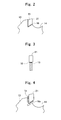
- Fig. 1 illustrates a circular saw blade 10 as a cutting tool according to an embodiment in a front view.
- the circular saw blade 10 is provided with a body metal 11 that is a disc-shaped body made of steel.
- the body metal 11 is a thin plate made of steel having a carbon content of 0.5 mass% or more, Vickers' hardness of 700 HV or less, and a thickness of 2 mm, and is provided with a center hole 12 fitted to a rotation axis of a processing machine at a center thereof.
- An outer peripheral side of the body metal 11 becomes bases 13 radially projecting in the radial direction at multiple positions with equal intervals in a circumferential direction, and a gullet 14 relatively recessed in the radial direction is provided between the bases 13.
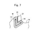
- On a distal end side of a rotation front side of the base 13, as illustrated in Fig. 2 in detail, multiple mounting seats 15 for mounting a cutting edge tip 21 as an edge metal are provided by cutting in a V shape at a central angle of substantially 60
- the cutting edge tip 21 is joined to the mounting seat 15 with a thin intermediate layer 18 made of nickel alloy interposed therebetween.
- nickel alloy Fe-Ni, Fe-Ni-Co or the like is adopted.
- material of the intermediate layer 18 in place of the nickel alloy, pure nickel, a silver solder material, a copper solder material or the like may be adopted, and it is also possible to omit the intermediate layer as necessary.
- the cutting edge tip 21 is made of cemented carbide, has a quadrilateral shape having a thickness of 3 mm, and has a shape matched to close contact to the mounting seat 15.
- a thin nickel alloy piece 18a is mounted to the mounting seat 15 provided in the base 13 of the body metal 11 placed on a table that is not illustrated, and the cutting edge tip 21 is superimposed on and pressed against the nickel alloy piece 18a and is fitted to the mounting seat 15.
- the body metal 11 is fixed on the table by a clamp jig (not illustrated) in a portion near the base 13 in which the cutting edge tip 21 is welded.
- the clamping jig materials having satisfactory thermal conductivity such as copper are used. As a result, it is possible to quickly discharge heat during laser irradiation to be described later, thereby suppressing the influence due to heat to the body metal 11 and the cutting edge tip 21.
- the cutting edge tip 21 is preferably pressed against the mounting seat 15 by a pressing member such as a cutting edge tip pressure cylinder from the outside, and therefore, a cutting edge tip position does not move during welding. Thus, the subsequent welding of the cutting edge tip 21 to the mounting seat 15 is accurately performed.
- laser beam of predetermined high power using a fiber laser 23 is irradiated to the nickel alloy piece 18a as a boundary between the base 13 and the cutting edge tip 21 and the surface side of the base 13 in the periphery thereof to melt the base 13 and the nickel alloy piece 18a, and joining to the cutting edge tip 21 is formed.
- the base 13 is thin as 2 mm and the heat conduction is fast, even if the irradiation of laser light is performed only from one surface side of the base 13, uniform heating is performed.
- the base 13 is thick, in order to secure uniform conduction of heat to form uniform joining, it is preferred to irradiate laser beam from both sides of the base 13.
- the irradiation of the fiber laser 23 is performed to be inclined by substantially 10° to the base 13 side from a vertical direction with respect to the flat surface of the base 13, whereby unnecessary interference to incident light due to an occurrence of reflected beam is suppressed. Furthermore, during irradiation of the fiber laser 23, it is desirable to blow an inert shielding gas such as nitrogen gas or argon gas to the joint between the base 13 and the cutting edge tip 21, and thus, oxidation of the base 13 and the cutting edge tip 21 due to heating of radiation is suppressed.
- an inert shielding gas such as nitrogen gas or argon gas
- the tempering process of the body metal 11 is performed by re-irradiation of the fiber laser 23.
- the width of the irradiation region is widened by shifting the focus of the laser beam from the fiber laser 23, and tempering is performed by irradiation energy having the output lower than the welding process.
- re-irradiation is performed in a wide range by shifting the focus of the laser beam from the fiber laser 23 and by irradiation energy having the output lower than that in the welding.
- re-irradiation may be performed only by shifting the focus of the laser beam.
- the material of the cutting edge tip is not limited to the cemented carbide, and may be cermet, high-speed steel, various ceramics, polycrystalline diamond or the like.
- electron beam may also be used as high energy beam.
- the laser is not limited to the fiber laser, and may also be CO 2 laser, YAG laser, green laser or the like.
- the above-described embodiment is an example, and can be implemented with various modifications without departing from the scope of the invention.
Landscapes
- Engineering & Computer Science (AREA)
- Physics & Mathematics (AREA)
- Optics & Photonics (AREA)
- Mechanical Engineering (AREA)
- Plasma & Fusion (AREA)
- Laser Beam Processing (AREA)
- Nonmetal Cutting Devices (AREA)
Applications Claiming Priority (1)
| Application Number | Priority Date | Filing Date | Title |
|---|---|---|---|
| JP2013100101A JP2014217936A (ja) | 2013-05-10 | 2013-05-10 | 切削工具の製造方法 |
Publications (2)
| Publication Number | Publication Date |
|---|---|
| EP2801433A2 true EP2801433A2 (de) | 2014-11-12 |
| EP2801433A3 EP2801433A3 (de) | 2015-06-24 |
Family
ID=50677952
Family Applications (1)
| Application Number | Title | Priority Date | Filing Date |
|---|---|---|---|
| EP14166372.4A Withdrawn EP2801433A3 (de) | 2013-05-10 | 2014-04-29 | Verfahren zur Herstellung von Schneidwerkzeugen |
Country Status (3)
| Country | Link |
|---|---|
| EP (1) | EP2801433A3 (de) |
| JP (1) | JP2014217936A (de) |
| TW (1) | TW201443237A (de) |
Families Citing this family (4)
| Publication number | Priority date | Publication date | Assignee | Title |
|---|---|---|---|---|
| JP6684548B2 (ja) * | 2015-06-11 | 2020-04-22 | 株式会社アマダホールディングス | チップ接合方法 |
| JP2017087263A (ja) * | 2015-11-10 | 2017-05-25 | トヨタ自動車株式会社 | 溶接方法 |
| JP7079289B2 (ja) * | 2020-07-15 | 2022-06-01 | 住友重機械工業株式会社 | 減速装置用部品の熱処理方法 |
| WO2022158218A1 (ja) * | 2021-01-21 | 2022-07-28 | 兼房株式会社 | 長尺刃物 |
Citations (1)
| Publication number | Priority date | Publication date | Assignee | Title |
|---|---|---|---|---|
| JP3584716B2 (ja) | 1998-01-27 | 2004-11-04 | 松下電工株式会社 | 刃物の製造方法 |
Family Cites Families (6)
| Publication number | Priority date | Publication date | Assignee | Title |
|---|---|---|---|---|
| JP3449091B2 (ja) * | 1996-01-26 | 2003-09-22 | 松下電工株式会社 | 鋸 刃 |
| JPH10272586A (ja) * | 1997-03-31 | 1998-10-13 | Nippon Steel Corp | 金属管のレーザ突合せ溶接方法およびその装置 |
| JP2000288948A (ja) * | 1999-04-01 | 2000-10-17 | Nippon Steel Corp | 丸鋸の製造方法および丸鋸 |
| DE19931948B4 (de) * | 1999-07-09 | 2004-11-11 | Zwilling J. A. Henckels Ag | Verfahren zur Herstellung einer Klinge eines Schneidwerkzeuges und damit hergestelltes Erzeugnis |
| JP5654219B2 (ja) * | 2009-07-14 | 2015-01-14 | 富士重工業株式会社 | 摩擦攪拌接合用回転ツール |
| DE102012015766A1 (de) * | 2012-08-09 | 2013-03-14 | Daimler Ag | Verfahren zum Verschweißen zweier Bauteile miteinander |
-
2013
- 2013-05-10 JP JP2013100101A patent/JP2014217936A/ja active Pending
-
2014
- 2014-04-29 EP EP14166372.4A patent/EP2801433A3/de not_active Withdrawn
- 2014-04-30 TW TW103115449A patent/TW201443237A/zh unknown
Patent Citations (1)
| Publication number | Priority date | Publication date | Assignee | Title |
|---|---|---|---|---|
| JP3584716B2 (ja) | 1998-01-27 | 2004-11-04 | 松下電工株式会社 | 刃物の製造方法 |
Also Published As
| Publication number | Publication date |
|---|---|
| TW201443237A (zh) | 2014-11-16 |
| JP2014217936A (ja) | 2014-11-20 |
| EP2801433A3 (de) | 2015-06-24 |
Similar Documents
| Publication | Publication Date | Title |
|---|---|---|
| CN110026683B (zh) | 一种双金属带锯条焊接装置及方法 | |
| CN103507118B (zh) | 用于制造锯片的方法 | |
| EP2801433A2 (de) | Verfahren zur Herstellung von Schneidwerkzeugen | |
| KR101831584B1 (ko) | 상이한 두께의 재료의 레이저 용접 방법 | |
| EP3525972B1 (de) | Verfahren zur herstellung einer verzahnten klinge und vorrichtung zur herstellung solch einer klinge | |
| TWI673783B (zh) | 封裝基板之加工方法 | |
| KR20160022300A (ko) | 팁 부착 원형톱의 제조 방법 | |
| JP2012106325A (ja) | 切削加工方法 | |
| CN111001930A (zh) | 用于激光焊接的方法和设备 | |
| JP5185108B2 (ja) | 板状刃物の製造方法および固定治具 | |
| JP6441788B2 (ja) | レーザ加工装置、レーザ加工方法、光学系、及び肉盛り加工品 | |
| CN103522030A (zh) | 切削工具的制作方法 | |
| CN103286384B (zh) | 一种加工双金属带锯条的方法 | |
| JP3584716B2 (ja) | 刃物の製造方法 | |
| JP3449091B2 (ja) | 鋸 刃 | |
| CN104827182B (zh) | 一种带锯条根带激光焊接工艺 | |
| JP6684548B2 (ja) | チップ接合方法 | |
| CN101415520B (zh) | 板状切削工具和固定夹具 | |
| CN114309947A (zh) | 一种锆基非晶金属材料和不锈钢材料的激光焊接方法 | |
| JP2017059625A (ja) | シャント抵抗器の製造方法、および溶接済み板材の製造装置 | |
| JPH1094916A (ja) | 刃物及びその製造方法 | |
| GB2074070A (en) | Laser-welded shaving unit | |
| TW202543772A (zh) | 雷射加工裝置及雷射加工方法 | |
| US20230294206A1 (en) | Laser welding method for joining a non-sintered material to a sintered material, composite body, and use of a laser welding method | |
| JPH1098015A (ja) | ワイヤーソーのエンドレス接合方法 |
Legal Events
| Date | Code | Title | Description |
|---|---|---|---|
| PUAI | Public reference made under article 153(3) epc to a published international application that has entered the european phase |
Free format text: ORIGINAL CODE: 0009012 |
|
| 17P | Request for examination filed |
Effective date: 20140429 |
|
| AK | Designated contracting states |
Kind code of ref document: A2 Designated state(s): AL AT BE BG CH CY CZ DE DK EE ES FI FR GB GR HR HU IE IS IT LI LT LU LV MC MK MT NL NO PL PT RO RS SE SI SK SM TR |
|
| AX | Request for extension of the european patent |
Extension state: BA ME |
|
| PUAL | Search report despatched |
Free format text: ORIGINAL CODE: 0009013 |
|
| AK | Designated contracting states |
Kind code of ref document: A3 Designated state(s): AL AT BE BG CH CY CZ DE DK EE ES FI FR GB GR HR HU IE IS IT LI LT LU LV MC MK MT NL NO PL PT RO RS SE SI SK SM TR |
|
| AX | Request for extension of the european patent |
Extension state: BA ME |
|
| RIC1 | Information provided on ipc code assigned before grant |
Ipc: B23K 31/02 20060101AFI20150515BHEP Ipc: B23K 26/32 20140101ALI20150515BHEP Ipc: B23K 1/005 20060101ALI20150515BHEP Ipc: B23K 26/00 20140101ALI20150515BHEP |
|
| STAA | Information on the status of an ep patent application or granted ep patent |
Free format text: STATUS: THE APPLICATION IS DEEMED TO BE WITHDRAWN |
|
| 18D | Application deemed to be withdrawn |
Effective date: 20160105 |