EP2800643B1 - Cutting insert having curved ramps for insertion into a tool holder, cutting tool and method of assembly - Google Patents
Cutting insert having curved ramps for insertion into a tool holder, cutting tool and method of assembly Download PDFInfo
- Publication number
- EP2800643B1 EP2800643B1 EP12816359.9A EP12816359A EP2800643B1 EP 2800643 B1 EP2800643 B1 EP 2800643B1 EP 12816359 A EP12816359 A EP 12816359A EP 2800643 B1 EP2800643 B1 EP 2800643B1
- Authority
- EP
- European Patent Office
- Prior art keywords
- insert
- holder
- base jaw
- cutting
- jaw
- Prior art date
- Legal status (The legal status is an assumption and is not a legal conclusion. Google has not performed a legal analysis and makes no representation as to the accuracy of the status listed.)
- Active
Links
- 238000000034 method Methods 0.000 title claims description 8
- 238000003780 insertion Methods 0.000 title description 6
- 230000037431 insertion Effects 0.000 title description 6
- 238000006073 displacement reaction Methods 0.000 claims description 8
- 230000002093 peripheral effect Effects 0.000 claims description 6
- 238000001816 cooling Methods 0.000 description 4
- 230000007246 mechanism Effects 0.000 description 4
- 230000000694 effects Effects 0.000 description 2
- 238000000605 extraction Methods 0.000 description 2
- 239000002184 metal Substances 0.000 description 2
- 230000009471 action Effects 0.000 description 1
- 230000004075 alteration Effects 0.000 description 1
- 230000009286 beneficial effect Effects 0.000 description 1
- 230000008901 benefit Effects 0.000 description 1
- 238000010276 construction Methods 0.000 description 1
- 239000012809 cooling fluid Substances 0.000 description 1
- 239000012530 fluid Substances 0.000 description 1
- 238000005555 metalworking Methods 0.000 description 1
- 238000012986 modification Methods 0.000 description 1
- 230000004048 modification Effects 0.000 description 1
- 230000000717 retained effect Effects 0.000 description 1
Images


Classifications
-
- B—PERFORMING OPERATIONS; TRANSPORTING
- B23—MACHINE TOOLS; METAL-WORKING NOT OTHERWISE PROVIDED FOR
- B23B—TURNING; BORING
- B23B27/00—Tools for turning or boring machines; Tools of a similar kind in general; Accessories therefor
- B23B27/04—Cutting-off tools
-
- B—PERFORMING OPERATIONS; TRANSPORTING
- B23—MACHINE TOOLS; METAL-WORKING NOT OTHERWISE PROVIDED FOR
- B23B—TURNING; BORING
- B23B29/00—Holders for non-rotary cutting tools; Boring bars or boring heads; Accessories for tool holders
- B23B29/04—Tool holders for a single cutting tool
- B23B29/043—Tool holders for a single cutting tool with cutting-off, grooving or profile cutting tools, i.e. blade- or disc-like main cutting parts
-
- B—PERFORMING OPERATIONS; TRANSPORTING
- B23—MACHINE TOOLS; METAL-WORKING NOT OTHERWISE PROVIDED FOR
- B23B—TURNING; BORING
- B23B2200/00—Details of cutting inserts
- B23B2200/16—Supporting or bottom surfaces
- B23B2200/165—Supporting or bottom surfaces with one or more grooves
-
- B—PERFORMING OPERATIONS; TRANSPORTING
- B23—MACHINE TOOLS; METAL-WORKING NOT OTHERWISE PROVIDED FOR
- B23B—TURNING; BORING
- B23B2205/00—Fixation of cutting inserts in holders
- B23B2205/02—Fixation using an elastically deformable clamping member
-
- B—PERFORMING OPERATIONS; TRANSPORTING
- B23—MACHINE TOOLS; METAL-WORKING NOT OTHERWISE PROVIDED FOR
- B23B—TURNING; BORING
- B23B2260/00—Details of constructional elements
- B23B2260/078—Hand tools used to operate chucks or to assemble, adjust or disassemble tools or equipment used for turning, boring or drilling
- B23B2260/0785—Hand tools used to operate chucks or to assemble, adjust or disassemble tools or equipment used for turning, boring or drilling for unclamping cutting inserts
-
- Y—GENERAL TAGGING OF NEW TECHNOLOGICAL DEVELOPMENTS; GENERAL TAGGING OF CROSS-SECTIONAL TECHNOLOGIES SPANNING OVER SEVERAL SECTIONS OF THE IPC; TECHNICAL SUBJECTS COVERED BY FORMER USPC CROSS-REFERENCE ART COLLECTIONS [XRACs] AND DIGESTS
- Y10—TECHNICAL SUBJECTS COVERED BY FORMER USPC
- Y10T—TECHNICAL SUBJECTS COVERED BY FORMER US CLASSIFICATION
- Y10T29/00—Metal working
- Y10T29/49—Method of mechanical manufacture
- Y10T29/49826—Assembling or joining
- Y10T29/49863—Assembling or joining with prestressing of part
- Y10T29/49876—Assembling or joining with prestressing of part by snap fit
-
- Y—GENERAL TAGGING OF NEW TECHNOLOGICAL DEVELOPMENTS; GENERAL TAGGING OF CROSS-SECTIONAL TECHNOLOGIES SPANNING OVER SEVERAL SECTIONS OF THE IPC; TECHNICAL SUBJECTS COVERED BY FORMER USPC CROSS-REFERENCE ART COLLECTIONS [XRACs] AND DIGESTS
- Y10—TECHNICAL SUBJECTS COVERED BY FORMER USPC
- Y10T—TECHNICAL SUBJECTS COVERED BY FORMER US CLASSIFICATION
- Y10T407/00—Cutters, for shaping
- Y10T407/22—Cutters, for shaping including holder having seat for inserted tool
- Y10T407/2272—Cutters, for shaping including holder having seat for inserted tool with separate means to fasten tool to holder
- Y10T407/2282—Cutters, for shaping including holder having seat for inserted tool with separate means to fasten tool to holder including tool holding clamp and clamp actuator
- Y10T407/2286—Resiliently biased clamp jaw
- Y10T407/2288—Integral with holder
-
- Y—GENERAL TAGGING OF NEW TECHNOLOGICAL DEVELOPMENTS; GENERAL TAGGING OF CROSS-SECTIONAL TECHNOLOGIES SPANNING OVER SEVERAL SECTIONS OF THE IPC; TECHNICAL SUBJECTS COVERED BY FORMER USPC CROSS-REFERENCE ART COLLECTIONS [XRACs] AND DIGESTS
- Y10—TECHNICAL SUBJECTS COVERED BY FORMER USPC
- Y10T—TECHNICAL SUBJECTS COVERED BY FORMER US CLASSIFICATION
- Y10T407/00—Cutters, for shaping
- Y10T407/23—Cutters, for shaping including tool having plural alternatively usable cutting edges
-
- Y—GENERAL TAGGING OF NEW TECHNOLOGICAL DEVELOPMENTS; GENERAL TAGGING OF CROSS-SECTIONAL TECHNOLOGIES SPANNING OVER SEVERAL SECTIONS OF THE IPC; TECHNICAL SUBJECTS COVERED BY FORMER USPC CROSS-REFERENCE ART COLLECTIONS [XRACs] AND DIGESTS
- Y10—TECHNICAL SUBJECTS COVERED BY FORMER USPC
- Y10T—TECHNICAL SUBJECTS COVERED BY FORMER US CLASSIFICATION
- Y10T407/00—Cutters, for shaping
- Y10T407/28—Miscellaneous
Definitions
- the subject matter of the present application relates to grooving and parting cutting tools of the type in which a cutting insert is retained in a holder blade by means of a clamping force.
- Cutting tools for grooving and parting can be provided with a clamping mechanism for securely retaining a cutting insert within a holder blade.
- the holder blade can consist of a base jaw and clamping jaw where the cutting insert is clamped within the base jaw and clamping jaw.
- a key can be provided to aid the insertion and removal of the cutting insert into, and out of, the holder blade.
- a cutting tool comprising:
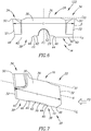
- FIGs. 1 and 2 showing a cutting tool 20, of the type used for grooving or parting, in accordance with a first embodiment of the subject matter of the present application.
- the cutting tool 20 has a cutting insert 22 and a holder blade 24 where the cutting insert 22 is resiliently clamped within the holder blade 24.
- the cutting insert 22 has an insert longitudinal axis A and is elongated in the same direction as said insert longitudinal axis A.
- the cutting insert 22 has an insert upper surface 26 and an opposing insert lower surface 28.
- the peripheral surface 30 has two opposing end surfaces 32 that extend between the insert upper surface 26 and the insert lower surface 28, defining a longitudinal insert length L.
- the insert upper and lower surfaces 26, 28 can extend substantially parallel to the insert longitudinal axis A.
- a cutting portion 34 Located at, and formed integrally with (i.e., having unitary one-piece construction with), at least one of the end surfaces 32 is a cutting portion 34. At least one of the cutting portions 34 can have a cutting edge 50 associated with the insert upper surface 26. In accordance with some embodiments of the subject matter of the present application there can be two cutting portions 34. In such a configuration, the cutting insert 22 can be double-ended and indexable and exhibit mirror symmetry about a median plane P1, where the median plane P1 is oriented perpendicular to the insert longitudinal axis A and is located midway between the end surfaces 32.
- one of the cutting portions 34 can be associated with the insert lower surface 28 (not shown), in which case the cutting insert 22, does not exhibit mirror symmetry about the median plane P1, although it may instead exhibit 180° rotational symmetry about a central axis passing perpendicularly to the sides of the insert.
- the insert upper surface 26 has an insert upper abutment surface 36 that is located between the end surfaces 32.
- the purpose of the insert upper abutment surface 36 is to provide an upper abutment zone between the cutting insert 22 and the holder blade 24 to ensure resilient clamping of the cutting insert 22.
- the insert upper abutment surface 36 can form an insert upper imaginary line L IU that is parallel to the insert longitudinal axis A of the cutting insert 22.
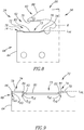
- the insert lower surface 28 has two longitudinally spaced apart insert lower component surfaces 38. Additionally, each insert lower component surface 38 has an insert lower abutment surface 40 .
- the purpose of the insert lower abutment surfaces 40 is to provide two lower spaced apart abutment zones between the cutting insert 22 and the holder blade 24 to ensure resilient clamping of the cutting insert 22.
- the spaced apart insert lower abutment surfaces 40 can form sections of an insert lower imaginary line L IL which is parallel to the insert longitudinal axis A.
- the insert lower surface 28 also has a non-abutting insert central lower surface 42 which is located between, and recessed with respect to, the insert lower component surfaces 38.
- the non-abutting insert central lower surface 42 is formed in a single, elongated lower insert cutout 29 which is visible in a side view of the cutting insert 22 and is bounded on one side by the insert lower imaginary line L IL .
- the elongated lower insert cutout 29 extends for at least one-third the length of the insert lower surface 28.
- the insert lower surface 28 has two insert lower intermediate surfaces 44, which extend between the insert central lower surface 42 and each insert lower component surface 38. At least one of the two insert lower component surfaces 38 includes an insert inner curved ramp 46 extending from its insert lower abutment surface 40 to the adjacent insert lower intermediate surface 44. Thus, as seen in the figures, the insert inner curved ramp 46 extends from the insert lower abutment surface 40 in a direction of the lower insert cutout 29.
- Each insert inner curved ramp 46 can have an insert inner radius of curvature R II , which subtends an insert inner angle of curvature ⁇ II , where ⁇ II can be greater than or equal to 20° and less than or equal to 40°.
- the insert inner angle of curvature ⁇ II can have a value of 30°.
- At least one of the two insert lower component surfaces 38 includes an insert outer curved ramp 48 extending from its insert lower abutment surface 40 in a direction of the adjacent end surface 32.
- Each insert outer curved ramp 48 can have an insert outer radius of curvature R IO , which subtends an insert outer angle of curvature ⁇ IO , where ⁇ IO can be greater or equal to 5° and less than or equal to 25°.
- the insert outer angle of curvature ⁇ IO can have a value of 15°.
- the insert outer radius of curvature R II can be equal to the insert outer radius of curvature R IO .
- both the insert lower component surfaces 38 have an insert inner curved ramp 46 and an insert outer curved ramp 48.
- the at least one insert inner curved ramp 46 can be tangential to its adjacent insert lower abutment surface 40 at the intersection thereof.
- the at least one insert outer curved ramp 48 can be tangential to its adjacent insert lower abutment surface 40 at the intersection thereof.
- the at least one insert inner curved ramp 46 can also be tangential to its adjacent insert lower intermediate surface 44 at the intersection thereof.
- the insert upper abutment surface 36 and the insert lower surface 28 can be generally V-shaped in an end view of the cutting insert 22.
- the insert upper abutment surface 36 and the insert lower surface 28 can be of a female groove type. This configuration, which provides a clamping mechanism whereby lateral displacement of the cutting insert 22, 122 is restricted when clamped within the holder blade 24, is well known and is not part of the invention.
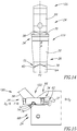
- the insert central lower surface 42 of the cutting insert 122 can have a substantially semi-circular insert central lower recess 52. It should be noted that the substantially semi-circular insert central lower recess 52 is provided for the insertion of a protrusion 54 of a key 56 (see Fig. 15 ) that can be pivoted in order to apply an urging force for the purpose of positioning the cutting insert 122 into its clamped position, relative to the holder blade 24.
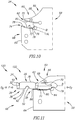
- Fig. 7 shows an example of a single-ended cutting insert 22 in accordance with the present application having a single cutting portion 34.
- the insert longitudinal axis A is not parallel to the feed direction FD of the cutting insert 22 when the cutting insert 22 is clamped in a blade holder 24 and engaging a workpiece.
- the insert longitudinal axis A can be parallel to the feed direction FD of the cutting insert 22 when the cutting insert 22 is clamped in a blade holder 24 and engaging a workpiece.
- the holder blade 24 has a holder longitudinal axis B that defines a forward to rearward direction D F , D R . It should be appreciated that use of the terms "forward” and “rearward” throughout the description and claims refer to a relative position in a direction of the holder longitudinal axis B towards the left and right, respectively, in Figs. 8 to 13 and 15 .
- the holder blade 24 has a body portion 58 and a clamping portion 60 integrally formed with the body portion 58.
- the clamping portion 60 has an insert receiving slot 62 opening out to a holder front end surface 64 of the holder blade 24.
- the insert receiving slot 62 has an upper clamping jaw 66 and a lower base jaw 68, where the upper clamping jaw 66 is resiliently displaceable with respect to the lower base jaw 68.
- the upper clamping jaw 66 has a clamping jaw abutment surface 70.
- the lower base jaw 68 has a base jaw lower surface 72.
- the base jaw lower surface 72 has two spaced apart base jaw component surfaces, a front base jaw component surface 74 adjacent the holder front end surface 64 and a rear base jaw component surface 76 rearwardly spaced apart from the front base jaw component surface 74.
- the front and rear base jaw component surfaces 74, 76 each have a holder lower abutment surface 78.
- the two spaced apart holder lower abutment surfaces 78 can form sections of a holder lower imaginary line L HL which is parallel to the holder longitudinal axis B.
- the base jaw lower surface 72 has a non-abutting base jaw central surface 80 located between, and recessed with respect to, the front and rear base jaw component surfaces 74, 76.
- the non-abutting base jaw central surface 80 is formed in a single, elongated base jaw cutout 73 which is visible in a side view of the holder blade 24 and is bounded on one side by the holder lower imaginary line L HL .
- the elongated base jaw cutout 73 extends for at least one-third the length of the base jaw lower surface 72.
- the base jaw lower surface 72 has two spaced apart holder lower intermediate surfaces 82, which extend between the base jaw central surface 80 and its adjacent front and rear base jaw component surfaces 74, 76.
- Each of the front and rear base jaw component surfaces 74, 76 can include a holder inner curved ramp 84 extending from its holder lower abutment surface 78 to the adjacent holder lower intermediate surface 82.
- Each holder inner curved ramp 84 can have a holder inner radius of curvature R HI , which subtends a holder inner angle of curvature ⁇ HI , where ⁇ HI can be greater or equal to 20° and less than or equal to 40°.
- the holder inner angle of curvature ⁇ HI can have a value of 30°.
- the front base jaw component surface 74 can include a holder outer curved ramp 86 extending from its holder lower abutment surface 78 to the adjacent holder front end surface 64.
- the holder outer curved ramp 86 can have a holder outer radius of curvature R HO , which subtends a holder outer angle of curvature ⁇ HO , where ⁇ HO can be greater or equal to 5° and less than or equal to 25°.
- the insert outer angle of curvature ⁇ HO can have a value of 15°.
- the holder outer radius of curvature R HI can be equal to the holder outer radius of curvature R HO .
- the two holder inner curved ramps 84 can be tangential to their adjacent holder lower abutment surface 78 at the intersection thereof.
- the one holder outer curved ramp 86 can be tangential to its adjacent holder lower abutment surface 78 at the intersection thereof.
- the two holder inner curved ramps 84 can be tangential to their adjacent holder lower intermediate surfaces 82 at the intersection thereof.
- the clamping jaw abutment surface 70 and the base jaw lower surface 72 can be generally V-shaped, in a front end view.
- the clamping jaw abutment surface 70 and the base jaw lower surface 72 can be of a male groove type. This configuration, which provides a clamping mechanism where the cutting insert 22, 122 can not be displaced laterally when clamped within the holder blade 24 is well known and is not part of the invention.
- FIG. 10 shows an example the holder blade 24 in accordance with the present application which is suitable for the single-ended cutting insert 22, 122 that is shown in Fig. 7 .
- the cutting tool 20 has a cutting insert 22 resiliently clamped between the upper clamping jaw 66 and the lower base jaw 68.
- the insert upper abutment surface 36 abuts the clamping jaw abutment surface 70
- the insert lower abutment surface 40 of the insert lower component surface 38 closest to the operative cutting portion 34 abuts the holder lower abutment surface 78 of the front base jaw component surface 74
- the insert lower abutment surface 40 of the insert lower component surface 38 furthest from the operative cutting portion 34 abuts the holder lower abutment surface 78 of the rear base jaw component surface 76.
- At least the insert lower component surface 38 closest to the operative cutting portion 34 has an insert inner curved ramp 46
- at least the insert lower component surface 38 furthest from the operative cutting portion 34 has an insert outer curved ramp 48.
- FIG. 11 Another aspect of the present application also includes a method of assembling the cutting tool 20, 120.
- Reference is first made to Fig. 11 showing the cutting insert 22 of the first embodiment, although the method is also applicable for the second embodiment of the cutting insert 122.
- the cutting insert 22, 122 is positioned relative to the holder blade 24 so that the insert longitudinal axis A and the holder longitudinal axis B are contained in a mutual main plane P2 and the insert lower surface 28 is in contact the base jaw lower surface 72 (see Fig. 14 ).
- the cutting insert 22, 122 is slid rearwardly until the upper clamping jaw 66 undergoes resilient displacement. It should be noted that greater than half the longitudinal insert length L can be rearward of the holder front end surface 64 before the upper clamping jaw 66 undergoes resilient displacement. This has the beneficial effect of reducing the remaining insertion distance for the cutting insert 22, 122 to reach a clamped position, whilst the upper clamping jaw 66 is resiliently displaced.
- an urging force F is applied to the cutting insert 22, 122 in the rearward direction D R until the insert lower abutment surface 40 of the insert lower component surface 38 closest to the operative cutting portion 34 abuts the holder lower abutment surface 78 of the front base jaw component surface 74 and the insert lower abutment surface 40 of the insert lower component surface 38 furthest from the operative cutting portion 34 abuts the holder lower abutment surface 78 of the rear base jaw component surface 76.
- the elongated lower insert cutout 29 opposes the elongated base jaw cutout 73, and the recessed insert central lower surface 42 opposes the recessed base jaw central surface 80, thereby forming a pass-through 93 between the cutting insert and base jaw lower surface 72, said pass-though 93 being visible in a side view of the assembled cutting tool.
- the method for assembling a longitudinally elongated cutting insert 22, 122 in a holder blade 24 requires no additional means for resiliently displacing the upper clamping jaw 66 relative to the lower base jaw 68.
- the upper clamping jaw 66 is devoid of a throughbore for the key 56 to engage with and widen the insert receiving slot 62.
- the upper clamping jaw 66 to be formed with a shape that is advantageous for the evacuation of metal chips and other debris.
- the internal angle ⁇ formed between an upper clamping jaw top surface 88 of the upper clamping jaw 66 and the clamping jaw abutment surface 70 can be reduced.
- Another advantage of the absence of a throughbore is the possibility to include a cooling system (not shown) in the upper clamping jaw 66 of the cutting tool 20, 120 whereby a cooling duct, for the provision of a cooling fluid, can extend through the upper clamping jaw 66.
- a cooling system not shown
- the existence of a throughbore in the upper clamping jaw 66 would significantly limit the path of such a cooling duct making it difficult for such a cooling system to be implemented.
- the ability to urge the cutting insert 22, 122 into a clamped position within the insert receiving slot 62, with no additional means for resiliently displacing the upper clamping jaw 66 relative to the lower base jaw 68, is achieved by having the insert central lower surface 42 and the base jaw central surface 80 recessed, which has the effect that the insert upper abutment surface 36 can slide freely relative to the clamping jaw abutment surface 70 and insert lower component surface 38 closest the operative cutting portion 34 can slide freely relative to the base jaw central surface 80 until at least one of the insert inner or outer curved ramps 46, 48 comes into contact with its respective front or rear base jaw component surfaces 74, 76. That is to say, until the upper clamping jaw 66 undergoes resilient displacement.
- the curved properties of the insert inner and outer curved ramps 46, 48 allow the cutting insert 22, 122 to be positioned in the clamping position in a smooth manner.
- the curved ramps also ensure there is a gradual increase in resistance to the insertion of the cutting insert 22, 122, caused by the resilient displacement of the upper clamping jaw 66, to the final clamping position, which allows the insertion of the cutting insert 22, 122 to be performed in a controlled and fluid fashion.
- the resilient clamping force provided by the upper clamping jaw 66 and the lower base jaw 68 is improved.
- the upper clamping jaw 66 in order to position the cutting insert 22, 122 into a clamping position, the upper clamping jaw 66 is displaced, relative to the lower base jaw 68, by a minimum distance. That is to say, the upper clamping jaw 66 is displaced only by the cutting insert 22, 122, and no additional space between the cutting insert 22, 122 and the upper clamping jaw 66 needs to be provided. Therefore, the resilience in the upper clamping jaw 66 is maximized to provide a greater clamping force.
- Another feature in accordance with the second embodiment of the present application having the cutting insert 122 with the insert central lower recess 52 is that, when removing the cutting insert 122 from the holder blade 24 with the key 56 and applying an extraction force F E on the insert central lower recess 52, the cutting insert 122 can be ejected from the insert receiving slot 62 in a controlled manner. This is achieved since, when pivoting the key 56 in a forward direction D F in order to remove the cutting insert 122, the protrusion 54 of the key 56 comes into contact with the front base jaw component surface 74 (see Fig. 15 ). This contact prevents the key 56 being pivoted further and occurs while the cutting insert 122 is still partially located in the insert receiving slot 62.
- the protrusion 54 of the key 56 can be removed from the insert central lower recess 52 so that the cutting insert 122 can be completely removed from the holder blade 24 in a controlled manner. If, for example, the extraction force F E is applied to the end surface 32 furthest from the operative cutting portion 34, the cutting insert 22 would be liable to be fully displaced from the insert receiving slot 62. It such a scenario, for a double-ended cutting insert for example, the tool operator may not know which cutting portion 34 has been used and which cutting portion is unused 34.
Landscapes
- Engineering & Computer Science (AREA)
- Mechanical Engineering (AREA)
- Cutting Tools, Boring Holders, And Turrets (AREA)
- Milling Processes (AREA)
- Knives (AREA)
Applications Claiming Priority (2)
| Application Number | Priority Date | Filing Date | Title |
|---|---|---|---|
| US201261582756P | 2012-01-03 | 2012-01-03 | |
| PCT/IL2012/050507 WO2013105080A1 (en) | 2012-01-03 | 2012-12-05 | Cutting insert having curved ramps for insertion into a tool holder, cutting tool and method of assembly |
Publications (2)
| Publication Number | Publication Date |
|---|---|
| EP2800643A1 EP2800643A1 (en) | 2014-11-12 |
| EP2800643B1 true EP2800643B1 (en) | 2020-02-26 |
Family
ID=47563567
Family Applications (1)
| Application Number | Title | Priority Date | Filing Date |
|---|---|---|---|
| EP12816359.9A Active EP2800643B1 (en) | 2012-01-03 | 2012-12-05 | Cutting insert having curved ramps for insertion into a tool holder, cutting tool and method of assembly |
Country Status (10)
| Country | Link |
|---|---|
| US (1) | US9033622B2 (pt) |
| EP (1) | EP2800643B1 (pt) |
| JP (1) | JP6111265B2 (pt) |
| KR (1) | KR101712249B1 (pt) |
| CN (1) | CN104023881B (pt) |
| BR (1) | BR112014016406A8 (pt) |
| CA (1) | CA2861725A1 (pt) |
| IN (1) | IN2014KN01123A (pt) |
| RU (1) | RU2014132077A (pt) |
| WO (1) | WO2013105080A1 (pt) |
Families Citing this family (9)
| Publication number | Priority date | Publication date | Assignee | Title |
|---|---|---|---|---|
| US8784014B2 (en) * | 2009-10-29 | 2014-07-22 | Kyocera Corporation | Cutting insert, cutting tool, and method of manufacturing machined product using the same |
| US9120239B2 (en) * | 2013-02-21 | 2015-09-01 | Iscar, Ltd. | Cutting tool and cutting insert having insert key recesses for extracting and mounting therein |
| KR102099857B1 (ko) * | 2013-12-27 | 2020-04-13 | 대구텍 유한회사 | 절삭인서트와 이를 포함하는 절삭공구 조립체 |
| US10010942B2 (en) * | 2016-06-20 | 2018-07-03 | Iscar, Ltd. | Cutting tool and cutting insert having a deep blind opening |
| CN114888317A (zh) * | 2016-09-06 | 2022-08-12 | 伊斯卡有限公司 | 用于分离的刀片插座和包括这种插座的刀具组件 |
| US10857603B2 (en) | 2019-03-19 | 2020-12-08 | Iscar, Ltd. | Insert holder having transversely oriented insert receiving pocket with upper stopper surface, cutting tool and cutting insert |
| US10953474B2 (en) | 2019-03-19 | 2021-03-23 | Iscar, Ltd. | Insert holder having transversely oriented insert receiving pocket with resilient upper jaw having outer flexibility groove and cutting tool |
| US11806793B2 (en) | 2021-11-03 | 2023-11-07 | Iscar, Ltd. | Cutting insert having laterally spaced apart, longitudinally extending wedge abutment surfaces, tool holder and cutting tool |
| US11904393B1 (en) | 2022-08-18 | 2024-02-20 | Iscar, Ltd. | External grooving insert holder having upper and lower jaws connected by angled hinge portion with cooling channel extending through hinge portion, and cutting tool |
Family Cites Families (24)
| Publication number | Priority date | Publication date | Assignee | Title |
|---|---|---|---|---|
| DE3219019A1 (de) | 1982-05-19 | 1983-11-24 | Zinner GmbH, 8500 Nürnberg | Ein- und mehrfachstechwerkzeug |
| DE3219150C3 (de) * | 1982-05-21 | 1991-06-13 | Karl Zinner | Stechwerkzeug mit selbstklemmendem schneideinsatz |
| SE441247B (sv) | 1984-02-20 | 1985-09-23 | Seco Tools Ab | Verktyg for spanskerande bearbetning, foretredesvis stickstal verktyg for spanskerande bearbetning, foretredesvis stickstal |
| AT388125B (de) * | 1987-07-22 | 1989-05-10 | Plansee Tizit Gmbh | Stechwerkzeug |
| IL84171A (en) * | 1987-10-14 | 1990-09-17 | Iscar Ltd | Cutting insert and tool holder therefor |
| IL91815A (en) * | 1989-09-28 | 1991-08-16 | Iscar Ltd | Cutting insert and cutting tool assembly incorporating such an insert |
| DE9317533U1 (de) * | 1993-11-16 | 1994-02-10 | Krupp Widia Gmbh | Halter für spanabhebende Werkzeugeinsätze |
| IL107675A (en) | 1993-11-19 | 1997-01-10 | Iscar Ltd | Clamping device for a cutting insert |
| US5516241A (en) * | 1994-06-27 | 1996-05-14 | Valenite Inc. | Holder blade |
| SE505399C2 (sv) | 1995-11-09 | 1997-08-18 | Sandvik Ab | Fastspänningsförfarande och fastspänningsanordning för skär |
| SE512319C2 (sv) | 1997-08-29 | 2000-02-28 | Sandvik Ab | Nyckel för skärhållare av bladtyp |
| IL127192A (en) | 1998-11-22 | 2008-06-05 | Gideon Barazani | Flexible fastening mechanism for applications |
| JP3069536U (ja) * | 1999-12-09 | 2000-06-23 | 日本ハードメタル株式会社 | 旋削用工具 |
| JP4709374B2 (ja) * | 2000-12-18 | 2011-06-22 | 住友電工ハードメタル株式会社 | 転削工具用スローアウェイチップと転削工具用チップ取付け座 |
| IL140593A (en) * | 2000-12-27 | 2009-02-11 | Gil Hecht | Spinning tool |
| EP1424151A1 (fr) | 2002-11-27 | 2004-06-02 | Applitec Moutier S.A. | Plaquette de coupe |
| IL160935A (en) * | 2004-03-18 | 2009-09-22 | Gil Hecht | Cutting tool and cutting tool for it |
| SE529021C2 (sv) | 2004-09-21 | 2007-04-10 | Seco Tools Ab | Skärverktyg |
| JP4770297B2 (ja) | 2004-12-16 | 2011-09-14 | 三菱マテリアル株式会社 | 切削インサートのクランプ機構および切削インサート |
| JP4918799B2 (ja) * | 2006-03-24 | 2012-04-18 | 三菱マテリアル株式会社 | 切削インサートのクランプ機構及びインサート着脱式切削工具 |
| IL194030A (en) * | 2008-09-11 | 2012-03-29 | Iscar Ltd | Cutting tool and cutting tool for it |
| AT509926B1 (de) | 2010-06-09 | 2012-12-15 | Boehlerit Gmbh & Co Kg | Schneidplatte und sägeblatt mit einer vielzahl derartiger schneidplatten |
| US8695189B2 (en) * | 2012-01-03 | 2014-04-15 | Iscar, Ltd. | Cutting tool key for mounting and extracting a cutting insert |
| US8647029B2 (en) * | 2012-01-03 | 2014-02-11 | Iscar, Ltd. | Cutting tool and method for extracting cutting insert therefrom |
-
2012
- 2012-03-20 US US13/425,152 patent/US9033622B2/en active Active
- 2012-12-05 RU RU2014132077A patent/RU2014132077A/ru unknown
- 2012-12-05 WO PCT/IL2012/050507 patent/WO2013105080A1/en active Application Filing
- 2012-12-05 KR KR1020147017603A patent/KR101712249B1/ko active IP Right Grant
- 2012-12-05 EP EP12816359.9A patent/EP2800643B1/en active Active
- 2012-12-05 BR BR112014016406A patent/BR112014016406A8/pt not_active Application Discontinuation
- 2012-12-05 JP JP2014549633A patent/JP6111265B2/ja not_active Expired - Fee Related
- 2012-12-05 CN CN201280065895.6A patent/CN104023881B/zh not_active Expired - Fee Related
- 2012-12-05 CA CA2861725A patent/CA2861725A1/en not_active Abandoned
-
2014
- 2014-05-26 IN IN1123/KOLNP/2014A patent/IN2014KN01123A/en unknown
Non-Patent Citations (1)
| Title |
|---|
| None * |
Also Published As
| Publication number | Publication date |
|---|---|
| CA2861725A1 (en) | 2013-07-18 |
| CN104023881B (zh) | 2016-12-28 |
| KR101712249B1 (ko) | 2017-03-03 |
| RU2014132077A (ru) | 2016-02-27 |
| BR112014016406A8 (pt) | 2017-07-04 |
| CN104023881A (zh) | 2014-09-03 |
| EP2800643A1 (en) | 2014-11-12 |
| JP2015506279A (ja) | 2015-03-02 |
| BR112014016406A2 (pt) | 2017-06-13 |
| IN2014KN01123A (en) | 2015-10-16 |
| JP6111265B2 (ja) | 2017-04-05 |
| US20130170917A1 (en) | 2013-07-04 |
| KR20140109904A (ko) | 2014-09-16 |
| US9033622B2 (en) | 2015-05-19 |
| WO2013105080A1 (en) | 2013-07-18 |
Similar Documents
| Publication | Publication Date | Title |
|---|---|---|
| EP2800643B1 (en) | Cutting insert having curved ramps for insertion into a tool holder, cutting tool and method of assembly | |
| EP2558235B1 (en) | Cutting tool | |
| EP2945765B1 (en) | Cutting tool with cutting insert having non-abutting side flanks | |
| EP1345723B1 (en) | Cutting tool | |
| EP2727671B1 (en) | Cutting insert | |
| EP2293896B1 (en) | Cutting tool and cutting insert therefor | |
| EP1918052B1 (en) | Cutting insert as well as combination of a cutting insert and an insert holder | |
| JP5390616B2 (ja) | 切削工具およびそのための切削チップ | |
| KR101918794B1 (ko) | 4-지점 접촉부들을 갖는 클램핑 홀더 및 인서트 | |
| EP1793951B1 (en) | Cutting tool | |
| US8695189B2 (en) | Cutting tool key for mounting and extracting a cutting insert | |
| EP3038777B1 (en) | Detachable cutting tool segment with resilient clamping and cutting tool therefor | |
| EP2958692B1 (en) | Cutting tool and cutting insert having insert key recesses for extracting and mounting therein | |
| EP3377256B1 (en) | Cutting tool and indexable cutting insert therefore | |
| EP1013364A2 (en) | Cutting tool assembly | |
| CN111417481B (zh) | 具有内偏刀片接收槽的铣槽工具主体、具有该工具主体和切削刀片的旋转切槽工具 | |
| US10953474B2 (en) | Insert holder having transversely oriented insert receiving pocket with resilient upper jaw having outer flexibility groove and cutting tool | |
| WO2017135291A1 (ja) | 刃先交換式バイト用ホルダ | |
| KR20120134111A (ko) | 절삭 인서트 및 절삭 공구 | |
| WO2020188554A1 (en) | Insert holder for a transversely oriented insert, cutting tool and cutting insert | |
| IL232910A (en) | Cutting insert, cutting tool and assembly method |
Legal Events
| Date | Code | Title | Description |
|---|---|---|---|
| PUAI | Public reference made under article 153(3) epc to a published international application that has entered the european phase |
Free format text: ORIGINAL CODE: 0009012 |
|
| 17P | Request for examination filed |
Effective date: 20140618 |
|
| AK | Designated contracting states |
Kind code of ref document: A1 Designated state(s): AL AT BE BG CH CY CZ DE DK EE ES FI FR GB GR HR HU IE IS IT LI LT LU LV MC MK MT NL NO PL PT RO RS SE SI SK SM TR |
|
| DAX | Request for extension of the european patent (deleted) | ||
| STAA | Information on the status of an ep patent application or granted ep patent |
Free format text: STATUS: EXAMINATION IS IN PROGRESS |
|
| 17Q | First examination report despatched |
Effective date: 20170216 |
|
| GRAP | Despatch of communication of intention to grant a patent |
Free format text: ORIGINAL CODE: EPIDOSNIGR1 |
|
| STAA | Information on the status of an ep patent application or granted ep patent |
Free format text: STATUS: GRANT OF PATENT IS INTENDED |
|
| INTG | Intention to grant announced |
Effective date: 20190909 |
|
| GRAS | Grant fee paid |
Free format text: ORIGINAL CODE: EPIDOSNIGR3 |
|
| GRAA | (expected) grant |
Free format text: ORIGINAL CODE: 0009210 |
|
| STAA | Information on the status of an ep patent application or granted ep patent |
Free format text: STATUS: THE PATENT HAS BEEN GRANTED |
|
| AK | Designated contracting states |
Kind code of ref document: B1 Designated state(s): AL AT BE BG CH CY CZ DE DK EE ES FI FR GB GR HR HU IE IS IT LI LT LU LV MC MK MT NL NO PL PT RO RS SE SI SK SM TR |
|
| REG | Reference to a national code |
Ref country code: GB Ref legal event code: FG4D |
|
| REG | Reference to a national code |
Ref country code: CH Ref legal event code: EP |
|
| REG | Reference to a national code |
Ref country code: DE Ref legal event code: R096 Ref document number: 602012068100 Country of ref document: DE |
|
| REG | Reference to a national code |
Ref country code: AT Ref legal event code: REF Ref document number: 1237028 Country of ref document: AT Kind code of ref document: T Effective date: 20200315 |
|
| REG | Reference to a national code |
Ref country code: IE Ref legal event code: FG4D |
|
| PG25 | Lapsed in a contracting state [announced via postgrant information from national office to epo] |
Ref country code: FI Free format text: LAPSE BECAUSE OF FAILURE TO SUBMIT A TRANSLATION OF THE DESCRIPTION OR TO PAY THE FEE WITHIN THE PRESCRIBED TIME-LIMIT Effective date: 20200226 Ref country code: RS Free format text: LAPSE BECAUSE OF FAILURE TO SUBMIT A TRANSLATION OF THE DESCRIPTION OR TO PAY THE FEE WITHIN THE PRESCRIBED TIME-LIMIT Effective date: 20200226 Ref country code: NO Free format text: LAPSE BECAUSE OF FAILURE TO SUBMIT A TRANSLATION OF THE DESCRIPTION OR TO PAY THE FEE WITHIN THE PRESCRIBED TIME-LIMIT Effective date: 20200526 |
|
| REG | Reference to a national code |
Ref country code: NL Ref legal event code: MP Effective date: 20200226 |
|
| REG | Reference to a national code |
Ref country code: LT Ref legal event code: MG4D |
|
| PG25 | Lapsed in a contracting state [announced via postgrant information from national office to epo] |
Ref country code: SE Free format text: LAPSE BECAUSE OF FAILURE TO SUBMIT A TRANSLATION OF THE DESCRIPTION OR TO PAY THE FEE WITHIN THE PRESCRIBED TIME-LIMIT Effective date: 20200226 Ref country code: IS Free format text: LAPSE BECAUSE OF FAILURE TO SUBMIT A TRANSLATION OF THE DESCRIPTION OR TO PAY THE FEE WITHIN THE PRESCRIBED TIME-LIMIT Effective date: 20200626 Ref country code: HR Free format text: LAPSE BECAUSE OF FAILURE TO SUBMIT A TRANSLATION OF THE DESCRIPTION OR TO PAY THE FEE WITHIN THE PRESCRIBED TIME-LIMIT Effective date: 20200226 Ref country code: BG Free format text: LAPSE BECAUSE OF FAILURE TO SUBMIT A TRANSLATION OF THE DESCRIPTION OR TO PAY THE FEE WITHIN THE PRESCRIBED TIME-LIMIT Effective date: 20200526 Ref country code: GR Free format text: LAPSE BECAUSE OF FAILURE TO SUBMIT A TRANSLATION OF THE DESCRIPTION OR TO PAY THE FEE WITHIN THE PRESCRIBED TIME-LIMIT Effective date: 20200527 Ref country code: LV Free format text: LAPSE BECAUSE OF FAILURE TO SUBMIT A TRANSLATION OF THE DESCRIPTION OR TO PAY THE FEE WITHIN THE PRESCRIBED TIME-LIMIT Effective date: 20200226 |
|
| PG25 | Lapsed in a contracting state [announced via postgrant information from national office to epo] |
Ref country code: NL Free format text: LAPSE BECAUSE OF FAILURE TO SUBMIT A TRANSLATION OF THE DESCRIPTION OR TO PAY THE FEE WITHIN THE PRESCRIBED TIME-LIMIT Effective date: 20200226 |
|
| PG25 | Lapsed in a contracting state [announced via postgrant information from national office to epo] |
Ref country code: SK Free format text: LAPSE BECAUSE OF FAILURE TO SUBMIT A TRANSLATION OF THE DESCRIPTION OR TO PAY THE FEE WITHIN THE PRESCRIBED TIME-LIMIT Effective date: 20200226 Ref country code: PT Free format text: LAPSE BECAUSE OF FAILURE TO SUBMIT A TRANSLATION OF THE DESCRIPTION OR TO PAY THE FEE WITHIN THE PRESCRIBED TIME-LIMIT Effective date: 20200719 Ref country code: ES Free format text: LAPSE BECAUSE OF FAILURE TO SUBMIT A TRANSLATION OF THE DESCRIPTION OR TO PAY THE FEE WITHIN THE PRESCRIBED TIME-LIMIT Effective date: 20200226 Ref country code: SM Free format text: LAPSE BECAUSE OF FAILURE TO SUBMIT A TRANSLATION OF THE DESCRIPTION OR TO PAY THE FEE WITHIN THE PRESCRIBED TIME-LIMIT Effective date: 20200226 Ref country code: EE Free format text: LAPSE BECAUSE OF FAILURE TO SUBMIT A TRANSLATION OF THE DESCRIPTION OR TO PAY THE FEE WITHIN THE PRESCRIBED TIME-LIMIT Effective date: 20200226 Ref country code: RO Free format text: LAPSE BECAUSE OF FAILURE TO SUBMIT A TRANSLATION OF THE DESCRIPTION OR TO PAY THE FEE WITHIN THE PRESCRIBED TIME-LIMIT Effective date: 20200226 Ref country code: CZ Free format text: LAPSE BECAUSE OF FAILURE TO SUBMIT A TRANSLATION OF THE DESCRIPTION OR TO PAY THE FEE WITHIN THE PRESCRIBED TIME-LIMIT Effective date: 20200226 Ref country code: DK Free format text: LAPSE BECAUSE OF FAILURE TO SUBMIT A TRANSLATION OF THE DESCRIPTION OR TO PAY THE FEE WITHIN THE PRESCRIBED TIME-LIMIT Effective date: 20200226 Ref country code: LT Free format text: LAPSE BECAUSE OF FAILURE TO SUBMIT A TRANSLATION OF THE DESCRIPTION OR TO PAY THE FEE WITHIN THE PRESCRIBED TIME-LIMIT Effective date: 20200226 |
|
| REG | Reference to a national code |
Ref country code: AT Ref legal event code: MK05 Ref document number: 1237028 Country of ref document: AT Kind code of ref document: T Effective date: 20200226 |
|
| REG | Reference to a national code |
Ref country code: DE Ref legal event code: R097 Ref document number: 602012068100 Country of ref document: DE |
|
| PLBE | No opposition filed within time limit |
Free format text: ORIGINAL CODE: 0009261 |
|
| STAA | Information on the status of an ep patent application or granted ep patent |
Free format text: STATUS: NO OPPOSITION FILED WITHIN TIME LIMIT |
|
| PG25 | Lapsed in a contracting state [announced via postgrant information from national office to epo] |
Ref country code: AT Free format text: LAPSE BECAUSE OF FAILURE TO SUBMIT A TRANSLATION OF THE DESCRIPTION OR TO PAY THE FEE WITHIN THE PRESCRIBED TIME-LIMIT Effective date: 20200226 Ref country code: IT Free format text: LAPSE BECAUSE OF FAILURE TO SUBMIT A TRANSLATION OF THE DESCRIPTION OR TO PAY THE FEE WITHIN THE PRESCRIBED TIME-LIMIT Effective date: 20200226 |
|
| 26N | No opposition filed |
Effective date: 20201127 |
|
| PG25 | Lapsed in a contracting state [announced via postgrant information from national office to epo] |
Ref country code: SI Free format text: LAPSE BECAUSE OF FAILURE TO SUBMIT A TRANSLATION OF THE DESCRIPTION OR TO PAY THE FEE WITHIN THE PRESCRIBED TIME-LIMIT Effective date: 20200226 Ref country code: PL Free format text: LAPSE BECAUSE OF FAILURE TO SUBMIT A TRANSLATION OF THE DESCRIPTION OR TO PAY THE FEE WITHIN THE PRESCRIBED TIME-LIMIT Effective date: 20200226 |
|
| REG | Reference to a national code |
Ref country code: CH Ref legal event code: PL |
|
| GBPC | Gb: european patent ceased through non-payment of renewal fee |
Effective date: 20201205 |
|
| PG25 | Lapsed in a contracting state [announced via postgrant information from national office to epo] |
Ref country code: MC Free format text: LAPSE BECAUSE OF FAILURE TO SUBMIT A TRANSLATION OF THE DESCRIPTION OR TO PAY THE FEE WITHIN THE PRESCRIBED TIME-LIMIT Effective date: 20200226 |
|
| REG | Reference to a national code |
Ref country code: BE Ref legal event code: MM Effective date: 20201231 |
|
| PG25 | Lapsed in a contracting state [announced via postgrant information from national office to epo] |
Ref country code: FR Free format text: LAPSE BECAUSE OF NON-PAYMENT OF DUE FEES Effective date: 20201231 Ref country code: LU Free format text: LAPSE BECAUSE OF NON-PAYMENT OF DUE FEES Effective date: 20201205 Ref country code: IE Free format text: LAPSE BECAUSE OF NON-PAYMENT OF DUE FEES Effective date: 20201205 |
|
| PG25 | Lapsed in a contracting state [announced via postgrant information from national office to epo] |
Ref country code: GB Free format text: LAPSE BECAUSE OF NON-PAYMENT OF DUE FEES Effective date: 20201205 Ref country code: CH Free format text: LAPSE BECAUSE OF NON-PAYMENT OF DUE FEES Effective date: 20201231 Ref country code: LI Free format text: LAPSE BECAUSE OF NON-PAYMENT OF DUE FEES Effective date: 20201231 |
|
| PG25 | Lapsed in a contracting state [announced via postgrant information from national office to epo] |
Ref country code: TR Free format text: LAPSE BECAUSE OF FAILURE TO SUBMIT A TRANSLATION OF THE DESCRIPTION OR TO PAY THE FEE WITHIN THE PRESCRIBED TIME-LIMIT Effective date: 20200226 Ref country code: MT Free format text: LAPSE BECAUSE OF FAILURE TO SUBMIT A TRANSLATION OF THE DESCRIPTION OR TO PAY THE FEE WITHIN THE PRESCRIBED TIME-LIMIT Effective date: 20200226 Ref country code: CY Free format text: LAPSE BECAUSE OF FAILURE TO SUBMIT A TRANSLATION OF THE DESCRIPTION OR TO PAY THE FEE WITHIN THE PRESCRIBED TIME-LIMIT Effective date: 20200226 |
|
| PG25 | Lapsed in a contracting state [announced via postgrant information from national office to epo] |
Ref country code: MK Free format text: LAPSE BECAUSE OF FAILURE TO SUBMIT A TRANSLATION OF THE DESCRIPTION OR TO PAY THE FEE WITHIN THE PRESCRIBED TIME-LIMIT Effective date: 20200226 Ref country code: AL Free format text: LAPSE BECAUSE OF FAILURE TO SUBMIT A TRANSLATION OF THE DESCRIPTION OR TO PAY THE FEE WITHIN THE PRESCRIBED TIME-LIMIT Effective date: 20200226 |
|
| PG25 | Lapsed in a contracting state [announced via postgrant information from national office to epo] |
Ref country code: BE Free format text: LAPSE BECAUSE OF NON-PAYMENT OF DUE FEES Effective date: 20201231 |
|
| PGFP | Annual fee paid to national office [announced via postgrant information from national office to epo] |
Ref country code: DE Payment date: 20231106 Year of fee payment: 12 |