EP2799894B1 - Système de surveillance et véhicule - Google Patents
Système de surveillance et véhicule Download PDFInfo
- Publication number
- EP2799894B1 EP2799894B1 EP12859990.9A EP12859990A EP2799894B1 EP 2799894 B1 EP2799894 B1 EP 2799894B1 EP 12859990 A EP12859990 A EP 12859990A EP 2799894 B1 EP2799894 B1 EP 2799894B1
- Authority
- EP
- European Patent Office
- Prior art keywords
- signal
- section
- diagnosis
- monitoring
- voltage
- Prior art date
- Legal status (The legal status is an assumption and is not a legal conclusion. Google has not performed a legal analysis and makes no representation as to the accuracy of the status listed.)
- Active
Links
- 238000012544 monitoring process Methods 0.000 title claims description 118
- 238000004092 self-diagnosis Methods 0.000 claims description 74
- 238000003745 diagnosis Methods 0.000 claims description 54
- 230000002159 abnormal effect Effects 0.000 claims description 7
- 238000001514 detection method Methods 0.000 description 80
- 238000000034 method Methods 0.000 description 27
- 230000005764 inhibitory process Effects 0.000 description 10
- 238000012545 processing Methods 0.000 description 10
- 238000009825 accumulation Methods 0.000 description 4
- 230000007488 abnormal function Effects 0.000 description 3
- PXHVJJICTQNCMI-UHFFFAOYSA-N Nickel Chemical compound [Ni] PXHVJJICTQNCMI-UHFFFAOYSA-N 0.000 description 2
- 238000010586 diagram Methods 0.000 description 2
- UFHFLCQGNIYNRP-UHFFFAOYSA-N Hydrogen Chemical compound [H][H] UFHFLCQGNIYNRP-UHFFFAOYSA-N 0.000 description 1
- HBBGRARXTFLTSG-UHFFFAOYSA-N Lithium ion Chemical compound [Li+] HBBGRARXTFLTSG-UHFFFAOYSA-N 0.000 description 1
- 239000003990 capacitor Substances 0.000 description 1
- 238000012508 change request Methods 0.000 description 1
- 238000002485 combustion reaction Methods 0.000 description 1
- 238000004891 communication Methods 0.000 description 1
- 230000000694 effects Effects 0.000 description 1
- 239000000446 fuel Substances 0.000 description 1
- 229910052739 hydrogen Inorganic materials 0.000 description 1
- 239000001257 hydrogen Substances 0.000 description 1
- 229910001416 lithium ion Inorganic materials 0.000 description 1
- 238000005259 measurement Methods 0.000 description 1
- 229910052759 nickel Inorganic materials 0.000 description 1
- 230000001172 regenerating effect Effects 0.000 description 1
Images


Classifications
-
- G—PHYSICS
- G01—MEASURING; TESTING
- G01R—MEASURING ELECTRIC VARIABLES; MEASURING MAGNETIC VARIABLES
- G01R31/00—Arrangements for testing electric properties; Arrangements for locating electric faults; Arrangements for electrical testing characterised by what is being tested not provided for elsewhere
- G01R31/28—Testing of electronic circuits, e.g. by signal tracer
- G01R31/317—Testing of digital circuits
- G01R31/3181—Functional testing
- G01R31/3187—Built-in tests
-
- G—PHYSICS
- G01—MEASURING; TESTING
- G01R—MEASURING ELECTRIC VARIABLES; MEASURING MAGNETIC VARIABLES
- G01R31/00—Arrangements for testing electric properties; Arrangements for locating electric faults; Arrangements for electrical testing characterised by what is being tested not provided for elsewhere
- G01R31/36—Arrangements for testing, measuring or monitoring the electrical condition of accumulators or electric batteries, e.g. capacity or state of charge [SoC]
- G01R31/382—Arrangements for monitoring battery or accumulator variables, e.g. SoC
- G01R31/3835—Arrangements for monitoring battery or accumulator variables, e.g. SoC involving only voltage measurements
-
- G—PHYSICS
- G01—MEASURING; TESTING
- G01R—MEASURING ELECTRIC VARIABLES; MEASURING MAGNETIC VARIABLES
- G01R31/00—Arrangements for testing electric properties; Arrangements for locating electric faults; Arrangements for electrical testing characterised by what is being tested not provided for elsewhere
- G01R31/36—Arrangements for testing, measuring or monitoring the electrical condition of accumulators or electric batteries, e.g. capacity or state of charge [SoC]
- G01R31/382—Arrangements for monitoring battery or accumulator variables, e.g. SoC
-
- G—PHYSICS
- G01—MEASURING; TESTING
- G01R—MEASURING ELECTRIC VARIABLES; MEASURING MAGNETIC VARIABLES
- G01R31/00—Arrangements for testing electric properties; Arrangements for locating electric faults; Arrangements for electrical testing characterised by what is being tested not provided for elsewhere
- G01R31/36—Arrangements for testing, measuring or monitoring the electrical condition of accumulators or electric batteries, e.g. capacity or state of charge [SoC]
- G01R31/396—Acquisition or processing of data for testing or for monitoring individual cells or groups of cells within a battery
Definitions
- the present invention relates to a self-diagnosis technique for a monitoring section that acquires information on the charge and discharge state of an electric storage device.
- the assembled battery of this type includes a monitoring section which monitors the charge and discharge state (for example, overcharge and overdischarge) of the assembled battery on the basis of information acquired by a voltage detection circuit included in the monitoring section.
- a voltage detection circuit included in the monitoring section.
- an abnormal event may occur in the voltage detection circuit itself can also be conceived.
- Patent Literature 1 Disclosed in Patent Literature 1 is an overcharge detector for an on-board secondary battery to which charge and discharge control is provided in accordance with a charge control target value during the operation of the vehicle .
- the overcharge detector for the on-board secondary battery includes: a first overvoltage detection circuit for detecting an overcharge of the secondary voltage; a second overvoltage detection circuit for detecting an overcharge of the secondary voltage, the second overvoltage detection circuit being provided in parallel to the first overvoltage detection circuit; and a self-diagnosis section configured to execute a self-diagnosis for detecting an abnormal event in the first and second overvoltage detection circuits when the operation of the vehicle is ended.
- the self-diagnosis section includes: a diagnosis start determination section for directing the execution of the self-diagnosis on conditions that at the time of the request for the self-diagnosis, the voltage of the secondary battery is within a predetermined voltage range that permits the self-diagnosis of the first and second overvoltage detection circuits; and a change request section for requesting a change in the charge control target value during the next operation of the vehicle to a value higher than the current value when the diagnosis start determination section has determined that the voltage of the secondary battery at the time of the request for the self-diagnosis is lower than the predetermined voltage range.
- US 2010/301868 discloses a voltage monitoring apparatus including a plurality of voltage monitoring sections corresponding to a plurality of blocks of unit cells of a multiple-set battery respectively and a main control section.
- Each of the voltage monitoring section includes a voltage detection section which detects voltages of the unit cells of a corresponding block, a voltage adjustment section which adjusts the voltages of the unit cells of the corresponding block so that the voltages are uniformized, an active power source which obtains power from the unit cells of the corresponding block, and supplies power to the voltage detection section and the voltage adjustment section, a power source switching section which switches a power supply mode and a power disconnect mode of the active power source, and a low consumption power source which obtains the power from the unit cells of the corresponding block, and supplies power to the power source switching section.
- the main control section includes a failure diagnosis section which performs a failure diagnosis of each of the voltage monitoring sections, and a switching control section which controls to disconnect a supply of the power from the active power source when a result of the failure diagnosis indicates a failure.
- JP 2009-216447 discloses a device including a voltage detection means detecting a voltage of a cell constructing the battery pack and a failure diagnosis means carrying out a first determination based on the detected cell voltage and a first determination threshold, carrying out the first determination based on the detected cell voltage and a second determination threshold, carrying out a second determination based on the detected cell voltage and the second determination threshold, carrying out the second determination based on the detected cell voltage and the first determination threshold, and carrying out a failure diagnosis of a determination means based on the first and the second determination results.
- US 2011/025271 discloses a state monitoring apparatus including a high-voltage side monitoring section having monitoring units assigned to respective unit batteries and a low-voltage side monitoring section having a control device.
- the monitoring units measures the voltages of the unit batteries upon reception of a voltage measurement command transmitted from the control device, and determines whether or not the measured voltages are within a predetermined range. This determination is transmitted to the control device. If this determination is negative, the control device limits a charge/discharge current of the assembled battery, and then causes the monitoring units to transmit the measured voltages.
- Patent Literature 1 Japanese Patent Application Laid-Open No. 2010-203790
- FIG. 1 is a view illustrating the configuration of the vehicle.
- Vehicles of this type may include hybrid automobiles and electric cars.
- the hybrid automobile is a vehicle which includes a assembled battery as well as another power source, such as an internal combustion engine or a fuel cell, as a power source for outputting energy to be used for running the vehicle.
- the electric car is a vehicle which includes only a assembled battery as the power source of the vehicle.
- the vehicle of the present example can also be supplied with power from an external power source so as to charge the assembled battery.
- the battery system of the present example has a assembled battery 10.
- the assembled battery 10 has a plurality of electric cells 11 which are connected in series.
- the electric cell 11 to be employed may be a secondary battery such as a nickel hydrogen battery or a lithium ion battery.
- a secondary battery such as a nickel hydrogen battery or a lithium ion battery.
- the number of electric cells 11 can be set, as appropriate, on the basis of the output to be required or the like. In the present example, although a plurality of electric cells 11 are connected in series, a plurality of electric cells 11 connected in parallel may also be included in the assembled battery 10.
- a monitoring unit 20 monitors the charge and discharge state (the voltage value or the current value) of the assembled battery 10.
- the monitoring unit 20 includes voltage detection circuits 21 which detect the voltage of each electric cell 11.
- the monitoring unit 20 has two voltage detection circuits 21, and each of the voltage detection circuits 21 can detect the voltage of the battery block included in the assembled battery 10 (referred to as the block voltage).
- the assembled battery 10 is divided into two battery blocks, and each battery block is made up of a plurality of electric cells 11 that are connected in series.
- the block voltage is the total sum (total voltage) of the voltages of the plurality of electric cells 11 included in each battery block.
- the two voltage detection circuits 21 are provided so as to detect the voltages of the two battery blocks included in the assembled battery 10.
- the invention is not limited thereto. That is, the number of battery blocks can be set as appropriate.
- each battery block may only have to include at least two electric cells 11 that are connected in series.
- the voltage detection circuit 21 can be provided to the number of battery blocks.
- the voltage detection circuits 21 detect the voltage of a corresponding battery block as well as detect the voltage of each electric cell 11 included in the corresponding battery block.
- the voltage detection circuit 21 operates by receiving a control signal from a controller 22 included in the monitoring unit 20.
- detection information provided by the voltage detection circuits 21 is outputted to the controller 22.
- a current sensor 23 detects a charge and discharge current flowing through the assembled battery 10, and then outputs the detection result to the controller 22 of the monitoring unit 20.
- An ECU 24 outputs a control signal to system main relays 31, 32, and 33, thereby switching each of the system main relays 31 to 33 between ON and OFF. Furthermore, the ECU 24 outputs the control signal to charging relays 35 and 36, thereby switching each of the charging relays 35 and 36 between ON and OFF.
- the ECU 24 outputs a reference signal to the monitoring unit 20.
- the reference signal is a stepped signal which is made up of a High signal and a Low signal, and the timing at which the High signal and the Low signal are switched over (i.e., the period of the signal) is set to a particular value (hereafter referred to as the reference period).
- the positive electrode terminal of the assembled battery 10 is connected with the system main relay 31.
- the system main relay 31 is switched between ON and OFF by receiving the control signal from the ECU 24.
- the negative electrode terminal of the assembled battery 10 is connected with the system main relay 32.
- the system main relay 32 is switched between ON and OFF by receiving the control signal from the ECU 24.
- the system main relay 33 and a limiter resistor 34 are connected in parallel to the system main relay 32.
- the system mainrelay33 is switched between ON and OFF by receiving the control signal from the ECU 24.
- the limiter resistor 34 is used to reduce the flow of an inrush current when the assembled battery 10 is connected to an inverter 41.
- the information on the ignition switch of the vehicle (ON/OFF) is inputted to the monitoring unit 20, which then outputs the information on the ignition switch to the ECU 24.
- the assembled battery 10 is connected to the inverter 41.
- the ECU 24 switches the system main relay 31 from OFF to ON and as well, switches the system main relay 33 from OFF to ON. This allows a current to flow through the limiter resistor 34.
- the ECU 24 switches the system main relay 33 from ON to OFF. This completes the connection of the assembled battery 10 to the inverter 41.
- the ECU 24 switches the system main relays 31 and 32 from ON to OFF.
- the inverter 41 converts DC power from the assembled battery 10 into AC power so as to output the AC power to a motor generator 42.
- the motor generator 42 to be employed may be, for example, a three-phase AC motor.
- the motor generator 42 receives the AC power from the inverter 41 so as to produce kinetic energy for running the vehicle. The kinetic energy produced by the motor generator 42 is transmitted to drive wheels.
- the motor generator 42 converts the kinetic energy produced during braking of the vehicle into electric energy (AC power) .
- the inverter 41 converts AC power generated by the motor generator 42 into DC power, and then outputs the DC power to the assembled battery 10. This allows the assembled battery 10 to accumulate regenerative electric power.
- the assembled battery 10 is connected to the inverter 41.
- the invention is not limited thereto .
- the assembled battery 10 can also be connected to a voltage converter and then the voltage converter can be connected to the inverter 41.
- the voltage converter can be used to step up the output voltage of the assembled battery 10.
- the voltage converter can also step down the output voltage from the inverter 41 to the assembled battery 10.
- the lines (a positive electrode line PL and a negative electrode line NL) for connecting between the assembled battery 10 and the inverter 41 are connected with an AC charger 43.
- the AC charger 43 converts the AC power supplied from an external power supply into DC power, which is then supplied to the assembled battery 10.
- the AC charger 43 operates by receiving the control signal from the ECU 24. Power can be supplied from the external power supply to the AC charger 43 through a cable or in a non-contact manner.
- the external power supply is defined as a power source that is located at a place (outside the vehicle) that is different from the vehicle on which the battery system of the present example is mounted.
- the external power supply to be employed may be, for example, a commercial power supply.
- an AC power supply is used as the external power supply, but a DC power supply may also be employed.
- the AC charger 43 needs not to be used to convert AC power into DC power.
- the charging relay 35 is provided between the AC charger 43 and the positive electrode line PL and the charging relay 36 is provided between the AC charger 43 and the negative electrode line NL.
- the charging relays 35 and 36 receive the control signal from the ECU 24 so as to be switched between ON and OFF.
- the ECU 24 switches the charging relays 35 and 36 from OFF to ON.
- the system main relays 31 and 32 are in an ON state.
- the AC charger 43 is mounted on the vehicle.
- the present invention is also applicable even to a case in which the AC charger 43 is located at a place different from the vehicle.
- the battery system is provided with the charging relays 35 and 36, so that the ECU 24 provides ON/OFF control to the charging relays 35 and 36.
- the ECU 24 When the ECU 24 has determined that the charge and discharge state of the assembled battery 10 falls within an allowable range during charging the assembled battery 10 using the AC charger 43, the ECU 24 outputs, to the monitoring unit 20, a diagnosis permit signal for permitting the start of a self-diagnosis.
- the diagnosis permit signal is a unique stepped signal that has a period different from that of the reference signal.
- the self-diagnosis of the monitoring unit 20 is permitted when the charge and discharge state of the assembled battery 10 falls within an allowable range, that is, only when the assembled battery 10 is clearly not in an overcharge state and an over discharge state . This makes it possible to prevent the monitoring unit 20 from overlooking the overcharge state and the overdischarge state of the assembled battery 10 without detecting the states.
- the charge and discharge state falling within an allowable range means that the assembled battery 10 is at a normal accumulation level at which the assembled battery 10 is clearly not in an overcharge state and an overdischarge state.
- an error is found between the information on the voltage of the assembled battery 10 acquired by the monitoring unit 20 and the information on the actual voltage. Thus, by taking this error into account, it is necessary to set a normal accumulation level.
- the overcharge state means the state in which the amount of accumulation of the assembled battery 10 has reached a charge end voltage or the state in which the charge end voltage has been exceeded.
- the overdischarge state means the state in which the amount of accumulation of the assembled battery 10 has reached the discharge end voltage or the state in which the discharge end voltage has been exceeded.
- a voltage V 1 may be a voltage value of an electric cell 11 of those included in the assembled battery 10, the electric cell 11 having a voltage value that is farthest from the center value of the allowable range .
- the voltage V 1 may also be a block voltage or the total voltage of the assembled battery 10.
- a trigger signal for causing the monitoring unit 20 to start a self-diagnosis can be easily produced by controlling the period of the reference signal that is outputted by the ECU 24 to the monitoring unit 20 all the time. Since this eliminates the necessity of a separate circuit for producing the trigger signal, it is possible to reduce costs.
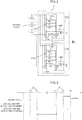
- Fig. 2 shows the configuration of the voltage detection circuit.
- the voltage detection circuit 21 has overvoltage detection circuits 210A and 210B which are provided in parallel corresponding to the respective battery blocks.
- the self-diagnosis may be carried out in various methods, and the invention is not limited the methods below.
- the overvoltage detection circuit 210A includes a potential divider section 212A and a voltage comparator section 216A.
- the potential divider section 212A includes a potential divider resistor 213A and a potential divider ratio control part 214A.
- the potential divider resistor 213A is made up of a plurality of resistor elements which are connected in series between a positive electrode Np and a negative electrode Nn of a battery block.
- the potential divider ratio control part 214A has switch elements SW0 to SWk which are each connected between a connection node between a plurality of resistor elements of the potential divider resistor 213A and a node Na to which a divided voltage is outputted.
- One of the switch elements SW0 to SWk is selectively turned ON in response to a control signal SDV1.
- the voltage comparator section 216A compares a predetermined reference voltage Vref with a divided voltage outputted to the node Na. Then, when the divided voltage is higher than the reference voltage Vref, a detection signal S1 is outputted, whereas the detection signal S1 is not outputted when the divided voltage is not higher than the reference voltage Vref.
- the potential divider ratio of the potential divider section 212A is set so that at the time of normal operation other than a self-diagnosis, the detection signal S1 is outputted when Vc > V(k), whereas the detection signal S1 is turned OFF when Vc ⁇ V(k). More specifically, the potential divider section 212A is designed to achieve the aforementioned potential divider ratio when the switch element SWk is selectively turned ON by the control signal SDV1.
- the potential divider section 212A is designed to achieve a potential divider ratio which allows the detection signal S1 to compare the levels between the block voltage Vc and the voltages V(0), V(1), and V(2) when the switch elements SW0 and SW1, SW2, ... are each turned ON in place of the switch element SWk. For example, when the switch element SW0 is selectively turned ON by the control signal SDV1, the detection signal S1 is turned ON when Vc > V(1), while the detection signal S1 is turned OFF when Vc ⁇ V(1).
- the potential divider section 212A is designed so that by switching among the switching positions of the switch elements, the detection signal S1 sequentially indicates the result of comparisons between the comparison voltages V(0), V(1), ..., V(k-1), and V(k) in increments of ⁇ V and the block voltage Vc.
- the switch element SWk is turned OFF at the time of a self-diagnosis of the monitoring unit 20, while any one of the other switches can be turned ON to be thereby capable of comparing the block voltage Vc with the comparison voltages V(0) to V(k-1) that are different from those at the time of normal operation.
- the overvoltage detection circuit 210B includes a potential divider section 212B and a voltage comparator section 216B.
- the potential divider section 212B includes a potential divider resistor 213B and a potential divider ratio control part 214B.
- the potential divider resistor 213B is made up of a plurality of resistor elements connected in series between the positive electrode Np and the negative electrode Nn of a battery block.
- the potential divider ratio control part 214B has the switch elements SW0 to SWk, and SWn which are each connected between a connection node between a plurality of resistor elements of the potential divider resistor 213B and a node Nb to which the divided voltage is outputted. Any one of the switch elements SW0 to SWk, and SWn is selectively turned ON in response to a control signal SDV2.
- the potential divider section 212B has a range of potential divider ratios different from that of the potential divider section 212A.
- a detection signal S2 indicates the result of a comparison between V(n) higher than the voltage V(k) and the block voltage Vc.
- the detection signal S2 indicates, like the detection signal S1, the result of a comparison between the comparison voltages V(0) to V(k) and the block voltage Vc.
- the overvoltage detection circuits 210A and 210B are provided to form a duplex system in parallel for a common battery block. Furthermore, as shown in Fig. 3 , during normal operation, it is possible to detect an overcharge at a level of the block voltage Vc > V(k) by the detection signal S1 from the overvoltage detection circuit 210A as well as to detect a serious overcharge at a level of the block voltage Vc > V (n) by the detection signal S2 from the overvoltage detection circuit 210B. Then, on the basis of the detection signals S1 and S1 from each overcharge detection circuit 200, the controller 22 shown in Fig. 1 turns ON an overcharge detection signal Foc1 when the detection signal S1 is turned ON in any one of the battery blocks, whereas turning ON an overcharge detection signal Foc2 when the detection signal S2 is turned ON in any one of the battery blocks.
- the self-diagnosis for detecting an abnormal event as described above in the overvoltage detection circuits 210A and 210B is executed as follows.
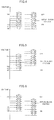
- Fig. 4 shows the result of a self-diagnosis in the case where there is no characteristic mismatch (offset) between the overvoltage detection circuits 210A and 210B and both the circuits are operating in a normal condition.
- control signals SDV1 and SDV2 are produced synchronously in the overvoltage detection circuits 210A and 210B so as to sequentially selectively turn ON the same ones of the switch elements SW0 to SWk.
- This causes the potential divider ratio of the potential divider sections 212A and 212B to be synchronously varied in a stepwise manner.
- the overvoltage detection circuits 210A and 210B can sequentially compare the block voltage with the comparison voltages V(0) to V(k) in parallel at the same time.
- the detection signal S1 of the overvoltage detection circuit 210A and the detection signal S2 of the overvoltage detection circuit 210B are changed from OFF to ON at the same timing in the process in which the potential divider ratio is varied in a stepwise manner so as to sequentially reduce, from V(k), the comparison voltage to be compared with the block voltage Vc.
- both the detection signals S1 and S2 are turned from OFF to ON at a point in time at which three steps have been taken. That is, when the detection signals S1 and S2 always coincide with each other, no characteristic mismatch occurs between the overvoltage detection circuits 210A and 210B, and it is thus possible to obtain a self-diagnosis result of being normal.
- Fig. 5 shows a self-diagnosis result in the case where the characteristics of the overvoltage detection circuit 210B are shifted toward a higher-voltage side
- Fig. 6 shows a self-diagnosis result in the case where the characteristics of the overvoltage detection circuit 210B are shifted toward a lower-voltage side.
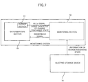
- Fig. 7 is a functional block diagram illustrating a monitoring system.
- a monitoring section 50 acquires information on the charge and discharge state of an electric storage device 70.
- the monitoring section 50 is equivalent to the monitoring unit 20, and the electric storage device 70 is equivalent to the assembled battery 10.
- a determination section 60 determines the charge and discharge state of the electric storage device 70 on the basis of the information acquired by the monitoring section 50. Referring to Figs. 1 and 7 to make a comparison therebetween, the determination section 60 is equivalent to the ECU 24.
- the determination section 60 has an output section 61 which continuously outputs a stepped signal made up of a High signal and a Low signal to the monitoring section 50.
- the determination section 60 outputs a diagnosis permit signal which is a unique stepped signal having a period different from that before the determination.
- the meaning of "the allowable range" has already been explained above, and will not be repeatedly mentioned.
- the monitoring section 50 executes a self-diagnosis of the monitoring section 50.
- the method of the "self-diagnosis" has already been explained above, and thus will not be repeatedly mentioned.
- the monitoring section 50 outputs (replies) the signal received from the output section 61 to the determination section 60 as an answerback signal.
- the determination section 60 will output again the diagnosis permit signal when the answerback signal in response to the diagnosis permit signal outputted to the monitoring section 50 is different from the diagnosis permit signal.
- the answerback signal in response to the diagnosis permit signal is a signal which has basically the same pattern as that of the diagnosis permit signal, but may also be a signal which has a pattern different from that of the diagnosis permit signal due to a noise or the like contained in the signal.
- the determination section 60 can determine by analyzing the answerback signal that the outputted signal has not been processed in the monitoring section 50 as the diagnosis permit signal. In this context, the determination section 60 outputs again the diagnosis permit signal to the monitoring section 50, thereby allowing for executing a self-diagnosis.
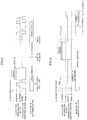
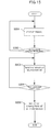
- Figs. 8 to 13 are a timing chart showing the processing performed by the monitoring system.
- the output section 61 according to this embodiment is assumed to output, during normal operation, a stepped signal (i.e., the aforementioned reference signal) which is obtained by alternately switching between the High signal (inhibition signal) and the Low signal (permit signal) with a period of one second.
- the normal operation means the operation in which the monitoring section 50 does not execute a self-diagnosis.
- the determination section 60 starts processing for determining whether to permit a self-diagnosis.
- the reference signal outputted from the output section 61 is received by the monitoring section 50 after a predetermined time has elapsed, and the monitoring section 50 outputs, as a rule, the same signal as that received from the output section 61 to the determination section 60 as the answerback signal.
- the monitoring section 50 outputs, as a rule, the same signal as that received from the output section 61 to the determination section 60 as the answerback signal.
- the output section 61 When the determination section 60 has determined that a self-diagnosis may be started, the output section 61 outputs, in place of the reference signal, a unique diagnosis permit signal that has a period different from that of the reference signal, the unique diagnosis permit signal having the High signal (inhibition signal) continued for two seconds or more and the Low signal (permit signal) continued for two seconds or more.
- the monitoring section 50 At a point in time at which the High signal has continued for two seconds or more and thereafter, the Low signal has continued for two seconds, the monitoring section 50 immediately starts a self-diagnosis.
- the monitoring section 50 outputs, to the determination section 60, a signal indicative of the end of the self-diagnosis, and the determination section 60 returns to the normal operation (i.e., the operation for outputting the reference signal).
- the output section 61 outputs the Low signal (permit signal) for two seconds or more. However, since the High signal (inhibition signal) has not been outputted for two seconds or more before the Low signal (permit signal) is outputted, the conditions for the diagnosis permit signal are not satisfied. In this case, the monitoring section 50 starts a self-diagnosis after the conditions for the diagnosis permit signal are established.
- Fig. 10 shows the case where the ignition switch is switched from ON to OFF after the monitoring section 50 has started a self-diagnosis.
- the self-diagnosis since the self-diagnosis is performed typically with the ignition switch in an OFF state, the self-diagnosis does not need to be interrupted even when the ignition switch has been switched from ON to OFF.
- the monitoring section 50 when the ignition switch has been switched from ON to OFF during a self-diagnosis, the monitoring section 50 does not interrupt but continues the self-diagnosis to the end thereof.
- Fig. 11 shows the case where a request to stop a self-diagnosis has been issued after the monitoring section 50 has started the self-diagnosis.
- the request to stop can be issued by a user, dealer or the like.
- the user or the like can request the monitoring section 50 to stop the self-diagnosis on a touch panel provided in the vehicle .
- the signal outputted from the output section 61 is switched from the diagnosis permit signal to the High signal (inhibition signal), and the monitoring section 50 interrupts the self-diagnosis at a point in time at which the High signal (inhibition signal) has continued for two seconds.
- Fig. 12 shows the case where there is provided a self-diagnosis time limit.
- the monitoring section 50 interrupts a self-diagnosis when the self-diagnosis is not completed within the self-diagnosis time limit after the self-diagnosis was started.
- the signal outputted from the output section 61 is switched from the diagnosis permit signal to the High signal (inhibition signal), and the monitoring section 50 interrupts the self-diagnosis at a point in time at which the High signal (inhibition signal) has continued for two seconds.
- Fig. 13 shows the case where the monitoring section 50 does not identify, as the diagnosis permit signal, the diagnosis permit signal outputted from the output section 61.
- the output section 61 outputs the diagnosis permit signal, but the Low signal (permit signal) contains noise.
- the condition for the diagnosis permit signal i.e., "that the inhibition signal continues for two seconds or more" prior to the permit signal is not satisfied.
- the monitoring section 50 cannot execute the self-diagnosis .
- the determination section 60 can determine that the diagnosis permit signal outputted from the determination section 60 has not been identified as the diagnosis permit signal.
- the output section 61 outputs again the diagnosis permit signal to cause the monitoring section 50 to execute a self-diagnosis.
- step S101 the determination section 60 determines whether the charge and discharge state of the assembled battery 10 falls within an allowable range. If the charge and discharge state of the assembled battery 10 falls within an allowable range, the process proceeds to step S102. In step S102, the determination section 60 switches the relays 35 and 36 of the AC charger 43 from ON to OFF so as to stop charging the assembled battery 10, and then the process proceeds to step S103.
- step S103 the determination section 60 outputs the diagnosis permit signal to the monitoring section 50, and then the process proceeds to step S104.
- step S104 the determination section 60 determines whether the monitoring section 50 has outputted the answerback signal. Then, the process proceeds to step S105 when the answerback signal is determined to have not yet been received, while the process proceeds to step S106 when the answerback signal is determined to have been received.
- step S105 the determination section 60 notifies the user or the like of the presence of an abnormal communication event.
- the notification means may be implemented by display on a display section provided inside the vehicle or by audio output from an audio output section.
- step S106 the determination section 60 determines on the basis of the answerback signal from the monitoring section 50 whether the monitoring section 50 has started a self-diagnosis .
- the process proceeds to step S107 when the self-diagnosis is determined to have not yet been started, while the process proceeds to step S109 when the self-diagnosis is determined to have been started.
- step S107 the determination section 60 determines whether the number of times of repeated outputs of the diagnosis permit signal has reached N times.
- the process proceeds to step S108 when the number of times of repeated outputs of the diagnosis permit signal has reached N times, while when the number of times of repeated outputs of the diagnosis permit signal has not yet reached N times, the process returns to step S103 to output the diagnosis permit signal again.
- the N times may be any number so long as the number is two or greater.
- the N times may be two or three.
- step S108 the determination section 60 determines that the monitoring section 50 has an abnormal function event.
- the determination section 60 notifies the user or the like of the presence of the abnormal function event.
- the notification means may be a method of displaying on a display section provided inside the passenger room of the vehicle or a method of outputting audio from an audio output section.
- step S109 the determination section 60 determines whether the signal which is transmitted by the monitoring section 50 and indicates that the self-diagnosis is completed has been received. When the signal indicative of the completion of the self-diagnosis has been received, the process proceeds to step S110.
- step S110 the determination section 60 switches the relays 35 and 36 of the AC charger 43 from OFF to ON and allows the assembled battery 10 to be charged, and the process then exits the flow.
- step S201 the monitoring section 50 receives a signal from the determination section 60, and then the process proceeds to step S202.
- the monitoring section 50 determines whether the signal received from the determination section 60 is a diagnosis permit signal. When the signal received from the determination section 60 is the diagnosis permit signal, the process proceeds to step S203.
- step S203 the monitoring section 50 starts the self-diagnosis, and then the process proceeds to step S204.
- step S204 the monitoring section 50 determines whether the self-diagnosis has been completed. When the self-diagnosis has been completed, then the process proceeds to step S205.
- step S205 the monitoring section 50 outputs, to the determination section 60, the signal indicating that the self-diagnosis has been completed, and the process then exits the flow.
- the monitoring section 50 determines whether the signal is the diagnosis permit signal on the basis of the durations of the High signal (inhibition signal) and the Low signal (permit signal) that are continuously outputted from the output circuit 61 of the determination section 60.
- the present invention is not limited thereto.
- the monitoring section 50 may also determine whether the signal is the diagnosis permit signal on the basis of the duty ratio of the High signal (inhibition signal) and the Low signal (permit signal) that are continuously outputted from the output circuit 61 of the determination section 60.
- the determination may be made on the basis of any criterion as long as the stepped signal outputted from the output circuit 61 during normal operation and the signal of the stepped signal outputted from the output circuit 61 at the time of permitting the start of a self-diagnosis have different periods.
- the monitoring section 50 outputs the answerback signal upon reception of the signal outputted from the determination section 60.
- the answerback signal can also be eliminated.
- the signal outputted from the monitoring section 50 may be desirably filtered so that the signal contains no noise.
Claims (4)
- Système de surveillance comprenant :une section de surveillance (50) destinée à acquérir de l'information sur un état de charge et de décharge d'un dispositif de stockage électrique (70) ; etune section de détermination (60) configurée pour déterminer si l'état de charge et de décharge du dispositif de stockage électrique (70) tombe dans une plage admissible sur la base de l'information acquise par la section de surveillance (50), dans lequella section de détermination (60) a une section de sortie (61) configurée pour délivrer de manière continue, à la section de surveillance (50), un signal étagé de référence composé d'un signal Haut et d'un signal Bas quand la section de surveillance (50) fonctionne dans un mode normal d'acquisition d'information liée à l'état de charge et de décharge, et quand l'état de charge et de décharge du dispositif de stockage électrique (70) a été déterminé comme tombant dans une plage admissible, la section de détermination (60) commande une période où le signal Haut et le signal Bas du signal étagé de référence délivré à la section de surveillance (50) qui fonctionne dans le mode normal pour être différente de la période avant la détermination et délivre un signal permettant un diagnostic en changeant le signal étagé de référence de façon à avoir un unique signal Haut et signal bas pour exécuter un autodiagnostic afin de détecter un événement anormal dans la section de surveillance (50), etla section de surveillance (50) est configurée pour déterminer si une série de signaux haut et de signaux bas reçus de manière continue de la section de détermination (60) correspond à une configuration unique de signaux haut et de signaux bas ayant le signal permettant un diagnostic, et lorsque l'on a déterminé qu'il y a correspondance, pour arrêter le fonctionnement en mode normal afin d'exécuter un autodiagnostic afin de détecter un événement anormal dans la section de surveillance (50).
- Système de surveillance selon la revendication 1, dans lequel, quand l'état de charge et de décharge du dispositif de stockage électrique (70) a été déterminé comme tombant dans une plage admissible pendant la charge, la section de détermination (60) arrête une opération de charge du dispositif de stockage électrique (70) avec l'exécution de l'autodiagnostic par la section de surveillance (50).
- Système de surveillance selon la revendication 1 ou 2, dans lequel
la section de surveillance (50) est configurée pour délivrer un signal reçu de la section de détermination (60) comme signal de réponse à la section de détermination (60) ; et
la section de détermination (60) est configurée pour délivrer de nouveau le signal permettant un diagnostic quand le signal de réponse en réponse au signal permettant un diagnostic délivré à la section de surveillance (50) est différent du signal permettant un diagnostic. - Véhicule ayant le système de surveillance selon l'une quelconque des revendications 1 à 3, dans lequel
le dispositif de stockage électrique (70) délivre de l'énergie à un moteur (42) pour un déplacement du véhicule et peut être chargé à partir d'une alimentation externe au véhicule.
Applications Claiming Priority (2)
| Application Number | Priority Date | Filing Date | Title |
|---|---|---|---|
| JP2011279687 | 2011-12-21 | ||
| PCT/JP2012/008181 WO2013094214A1 (fr) | 2011-12-21 | 2012-12-21 | Système de surveillance et véhicule |
Publications (3)
| Publication Number | Publication Date |
|---|---|
| EP2799894A1 EP2799894A1 (fr) | 2014-11-05 |
| EP2799894A4 EP2799894A4 (fr) | 2015-06-10 |
| EP2799894B1 true EP2799894B1 (fr) | 2020-10-14 |
Family
ID=48668131
Family Applications (1)
| Application Number | Title | Priority Date | Filing Date |
|---|---|---|---|
| EP12859990.9A Active EP2799894B1 (fr) | 2011-12-21 | 2012-12-21 | Système de surveillance et véhicule |
Country Status (5)
| Country | Link |
|---|---|
| US (1) | US9551750B2 (fr) |
| EP (1) | EP2799894B1 (fr) |
| JP (1) | JP5839047B2 (fr) |
| CN (1) | CN103998946B (fr) |
| WO (1) | WO2013094214A1 (fr) |
Families Citing this family (10)
| Publication number | Priority date | Publication date | Assignee | Title |
|---|---|---|---|---|
| CN104253464B (zh) | 2013-06-28 | 2017-05-03 | 比亚迪股份有限公司 | 电动汽车之间相互充电的系统及充电连接器 |
| CN104253471B (zh) * | 2013-06-28 | 2017-02-22 | 比亚迪股份有限公司 | 电动汽车的充电系统及电动汽车的充电控制方法 |
| JP6657011B2 (ja) * | 2016-05-20 | 2020-03-04 | ラピスセミコンダクタ株式会社 | 半導体装置、電池監視システムおよび診断方法 |
| JP6755136B2 (ja) * | 2016-07-13 | 2020-09-16 | 株式会社デンソーテン | 電圧検出装置および電圧検出方法 |
| TWI623173B (zh) * | 2016-12-06 | 2018-05-01 | 財團法人金屬工業研究發展中心 | 車輛馬達開關裝置 |
| US11173806B2 (en) * | 2017-01-11 | 2021-11-16 | Sanyo Electric Co., Ltd. | Management device and power storage system |
| US11018513B2 (en) * | 2017-07-31 | 2021-05-25 | Lg Chem, Ltd. | Battery cell management system |
| EP3627170B1 (fr) * | 2018-09-18 | 2023-03-22 | KNORR-BREMSE Systeme für Nutzfahrzeuge GmbH | Agencement de capteur et procédé de surveillance d'un système de stockage |
| JP7311458B2 (ja) * | 2020-04-07 | 2023-07-19 | トヨタ自動車株式会社 | バッテリー診断装置、方法、プログラム、及び車両 |
| JP7310747B2 (ja) * | 2020-07-28 | 2023-07-19 | 株式会社デンソー | 電圧検出装置 |
Family Cites Families (13)
| Publication number | Priority date | Publication date | Assignee | Title |
|---|---|---|---|---|
| JPH0453107Y2 (fr) * | 1988-06-20 | 1992-12-14 | ||
| CN2591920Y (zh) * | 2002-12-24 | 2003-12-10 | 鲁永忠 | Led疏散照明、标志灯智能集中应急供电控制装置 |
| JP2009201189A (ja) | 2008-02-19 | 2009-09-03 | Toyota Motor Corp | 電気システムの制御装置 |
| JP5092812B2 (ja) * | 2008-03-07 | 2012-12-05 | 日産自動車株式会社 | 組電池の監視装置および故障診断方法 |
| JP2010183672A (ja) | 2009-02-03 | 2010-08-19 | Toyota Motor Corp | 充電システム、電動車両および充電制御方法 |
| JP5187234B2 (ja) | 2009-02-27 | 2013-04-24 | トヨタ自動車株式会社 | 車載二次電池の過充電検出装置 |
| JP5355224B2 (ja) * | 2009-05-28 | 2013-11-27 | 矢崎総業株式会社 | 複数組電池の電圧監視装置 |
| JP4978662B2 (ja) | 2009-06-24 | 2012-07-18 | トヨタ自動車株式会社 | 充電状態推定装置および充電状態推定方法 |
| JP5099085B2 (ja) * | 2009-07-28 | 2012-12-12 | 株式会社デンソー | 組電池の状態監視装置 |
| JP5412245B2 (ja) * | 2009-11-09 | 2014-02-12 | 株式会社日立製作所 | リチウムイオン二次電池の診断システム及び診断方法 |
| EP2502776B1 (fr) * | 2009-11-17 | 2018-10-10 | Toyota Jidosha Kabushiki Kaisha | Véhicule et procédé de commande du véhicule |
| US8030973B2 (en) * | 2009-12-29 | 2011-10-04 | O2Micro Inc. | Calculating a parameter indicative of an error factor of a circuit |
| US8791669B2 (en) * | 2010-06-24 | 2014-07-29 | Qnovo Inc. | Method and circuitry to calculate the state of charge of a battery/cell |
-
2012
- 2012-12-21 CN CN201280061584.2A patent/CN103998946B/zh not_active Expired - Fee Related
- 2012-12-21 JP JP2013550131A patent/JP5839047B2/ja active Active
- 2012-12-21 WO PCT/JP2012/008181 patent/WO2013094214A1/fr active Application Filing
- 2012-12-21 US US14/367,400 patent/US9551750B2/en active Active
- 2012-12-21 EP EP12859990.9A patent/EP2799894B1/fr active Active
Non-Patent Citations (1)
| Title |
|---|
| None * |
Also Published As
| Publication number | Publication date |
|---|---|
| US20140333315A1 (en) | 2014-11-13 |
| CN103998946B (zh) | 2016-12-21 |
| CN103998946A (zh) | 2014-08-20 |
| JP5839047B2 (ja) | 2016-01-06 |
| JPWO2013094214A1 (ja) | 2015-04-27 |
| US9551750B2 (en) | 2017-01-24 |
| EP2799894A4 (fr) | 2015-06-10 |
| WO2013094214A1 (fr) | 2013-06-27 |
| EP2799894A1 (fr) | 2014-11-05 |
Similar Documents
| Publication | Publication Date | Title |
|---|---|---|
| EP2799894B1 (fr) | Système de surveillance et véhicule | |
| US9187000B2 (en) | Battery pack and electrically driven automobile | |
| US20180217206A1 (en) | Voltage monitoring module and voltage monitoring system | |
| US10386400B2 (en) | Abnormality detection device and method for insulation and welding | |
| US9669782B2 (en) | Electric power supply device using electric vehicle | |
| JP5753764B2 (ja) | 電池システム監視装置およびこれを備えた蓄電装置 | |
| US8125187B2 (en) | Method of controlling battery charging and discharging in a hybrid car power source | |
| US8269462B2 (en) | State monitoring apparatus for assembled battery | |
| US9634498B2 (en) | Electrical storage system and equalizing method | |
| WO2011040412A1 (fr) | Dispositif de commande de batterie assemblé | |
| US10343524B2 (en) | Weld detection apparatus and weld detection method | |
| JP2007282375A (ja) | ハイブリッド車両制御システム及びハイブリッド車両制御方法 | |
| US20120153961A1 (en) | Apparatus for monitoring operation state of battery pack composed of plurality of cells mutually connected in series | |
| US10161980B2 (en) | Deterioration detecting apparatus and deterioration detecting method | |
| JP5838224B2 (ja) | 電池制御装置 | |
| JP7140082B2 (ja) | センサ異常判定装置 | |
| JP2014223003A (ja) | 蓄電システム | |
| JP5049162B2 (ja) | 故障診断回路、及びこれを備えた電池パック | |
| CN112829635A (zh) | 电动车辆电池中的析锂检测和缓解 | |
| US20230118921A1 (en) | Monitoring device for battery | |
| Kawase et al. | New Battery Monitoring Unit for HEV/EV Lithium-ion Battery | |
| JP2014103840A (ja) | 蓄電システム | |
| JP2014223004A (ja) | 蓄電システム |
Legal Events
| Date | Code | Title | Description |
|---|---|---|---|
| PUAI | Public reference made under article 153(3) epc to a published international application that has entered the european phase |
Free format text: ORIGINAL CODE: 0009012 |
|
| 17P | Request for examination filed |
Effective date: 20140721 |
|
| AK | Designated contracting states |
Kind code of ref document: A1 Designated state(s): AL AT BE BG CH CY CZ DE DK EE ES FI FR GB GR HR HU IE IS IT LI LT LU LV MC MK MT NL NO PL PT RO RS SE SI SK SM TR |
|
| DAX | Request for extension of the european patent (deleted) | ||
| RA4 | Supplementary search report drawn up and despatched (corrected) |
Effective date: 20150511 |
|
| RIC1 | Information provided on ipc code assigned before grant |
Ipc: G01R 31/36 20060101AFI20150505BHEP |
|
| REG | Reference to a national code |
Ref country code: DE Ref legal event code: R079 Ref document number: 602012072829 Country of ref document: DE Free format text: PREVIOUS MAIN CLASS: G01R0031360000 Ipc: G01R0031383500 |
|
| GRAP | Despatch of communication of intention to grant a patent |
Free format text: ORIGINAL CODE: EPIDOSNIGR1 |
|
| STAA | Information on the status of an ep patent application or granted ep patent |
Free format text: STATUS: GRANT OF PATENT IS INTENDED |
|
| RIC1 | Information provided on ipc code assigned before grant |
Ipc: G01R 31/3835 20190101AFI20200414BHEP |
|
| INTG | Intention to grant announced |
Effective date: 20200508 |
|
| GRAS | Grant fee paid |
Free format text: ORIGINAL CODE: EPIDOSNIGR3 |
|
| GRAA | (expected) grant |
Free format text: ORIGINAL CODE: 0009210 |
|
| STAA | Information on the status of an ep patent application or granted ep patent |
Free format text: STATUS: THE PATENT HAS BEEN GRANTED |
|
| AK | Designated contracting states |
Kind code of ref document: B1 Designated state(s): AL AT BE BG CH CY CZ DE DK EE ES FI FR GB GR HR HU IE IS IT LI LT LU LV MC MK MT NL NO PL PT RO RS SE SI SK SM TR |
|
| REG | Reference to a national code |
Ref country code: GB Ref legal event code: FG4D |
|
| REG | Reference to a national code |
Ref country code: AT Ref legal event code: REF Ref document number: 1324094 Country of ref document: AT Kind code of ref document: T Effective date: 20201015 Ref country code: CH Ref legal event code: EP |
|
| REG | Reference to a national code |
Ref country code: DE Ref legal event code: R096 Ref document number: 602012072829 Country of ref document: DE |
|
| REG | Reference to a national code |
Ref country code: IE Ref legal event code: FG4D |
|
| REG | Reference to a national code |
Ref country code: AT Ref legal event code: MK05 Ref document number: 1324094 Country of ref document: AT Kind code of ref document: T Effective date: 20201014 |
|
| REG | Reference to a national code |
Ref country code: NL Ref legal event code: MP Effective date: 20201014 |
|
| PG25 | Lapsed in a contracting state [announced via postgrant information from national office to epo] |
Ref country code: GR Free format text: LAPSE BECAUSE OF FAILURE TO SUBMIT A TRANSLATION OF THE DESCRIPTION OR TO PAY THE FEE WITHIN THE PRESCRIBED TIME-LIMIT Effective date: 20210115 Ref country code: PT Free format text: LAPSE BECAUSE OF FAILURE TO SUBMIT A TRANSLATION OF THE DESCRIPTION OR TO PAY THE FEE WITHIN THE PRESCRIBED TIME-LIMIT Effective date: 20210215 Ref country code: NO Free format text: LAPSE BECAUSE OF FAILURE TO SUBMIT A TRANSLATION OF THE DESCRIPTION OR TO PAY THE FEE WITHIN THE PRESCRIBED TIME-LIMIT Effective date: 20210114 Ref country code: NL Free format text: LAPSE BECAUSE OF FAILURE TO SUBMIT A TRANSLATION OF THE DESCRIPTION OR TO PAY THE FEE WITHIN THE PRESCRIBED TIME-LIMIT Effective date: 20201014 Ref country code: RS Free format text: LAPSE BECAUSE OF FAILURE TO SUBMIT A TRANSLATION OF THE DESCRIPTION OR TO PAY THE FEE WITHIN THE PRESCRIBED TIME-LIMIT Effective date: 20201014 Ref country code: FI Free format text: LAPSE BECAUSE OF FAILURE TO SUBMIT A TRANSLATION OF THE DESCRIPTION OR TO PAY THE FEE WITHIN THE PRESCRIBED TIME-LIMIT Effective date: 20201014 |
|
| REG | Reference to a national code |
Ref country code: LT Ref legal event code: MG4D |
|
| PG25 | Lapsed in a contracting state [announced via postgrant information from national office to epo] |
Ref country code: SE Free format text: LAPSE BECAUSE OF FAILURE TO SUBMIT A TRANSLATION OF THE DESCRIPTION OR TO PAY THE FEE WITHIN THE PRESCRIBED TIME-LIMIT Effective date: 20201014 Ref country code: LV Free format text: LAPSE BECAUSE OF FAILURE TO SUBMIT A TRANSLATION OF THE DESCRIPTION OR TO PAY THE FEE WITHIN THE PRESCRIBED TIME-LIMIT Effective date: 20201014 Ref country code: IS Free format text: LAPSE BECAUSE OF FAILURE TO SUBMIT A TRANSLATION OF THE DESCRIPTION OR TO PAY THE FEE WITHIN THE PRESCRIBED TIME-LIMIT Effective date: 20210214 Ref country code: PL Free format text: LAPSE BECAUSE OF FAILURE TO SUBMIT A TRANSLATION OF THE DESCRIPTION OR TO PAY THE FEE WITHIN THE PRESCRIBED TIME-LIMIT Effective date: 20201014 Ref country code: ES Free format text: LAPSE BECAUSE OF FAILURE TO SUBMIT A TRANSLATION OF THE DESCRIPTION OR TO PAY THE FEE WITHIN THE PRESCRIBED TIME-LIMIT Effective date: 20201014 Ref country code: AT Free format text: LAPSE BECAUSE OF FAILURE TO SUBMIT A TRANSLATION OF THE DESCRIPTION OR TO PAY THE FEE WITHIN THE PRESCRIBED TIME-LIMIT Effective date: 20201014 Ref country code: BG Free format text: LAPSE BECAUSE OF FAILURE TO SUBMIT A TRANSLATION OF THE DESCRIPTION OR TO PAY THE FEE WITHIN THE PRESCRIBED TIME-LIMIT Effective date: 20210114 |
|
| PG25 | Lapsed in a contracting state [announced via postgrant information from national office to epo] |
Ref country code: HR Free format text: LAPSE BECAUSE OF FAILURE TO SUBMIT A TRANSLATION OF THE DESCRIPTION OR TO PAY THE FEE WITHIN THE PRESCRIBED TIME-LIMIT Effective date: 20201014 |
|
| REG | Reference to a national code |
Ref country code: DE Ref legal event code: R097 Ref document number: 602012072829 Country of ref document: DE |
|
| PG25 | Lapsed in a contracting state [announced via postgrant information from national office to epo] |
Ref country code: SK Free format text: LAPSE BECAUSE OF FAILURE TO SUBMIT A TRANSLATION OF THE DESCRIPTION OR TO PAY THE FEE WITHIN THE PRESCRIBED TIME-LIMIT Effective date: 20201014 Ref country code: RO Free format text: LAPSE BECAUSE OF FAILURE TO SUBMIT A TRANSLATION OF THE DESCRIPTION OR TO PAY THE FEE WITHIN THE PRESCRIBED TIME-LIMIT Effective date: 20201014 Ref country code: LT Free format text: LAPSE BECAUSE OF FAILURE TO SUBMIT A TRANSLATION OF THE DESCRIPTION OR TO PAY THE FEE WITHIN THE PRESCRIBED TIME-LIMIT Effective date: 20201014 Ref country code: SM Free format text: LAPSE BECAUSE OF FAILURE TO SUBMIT A TRANSLATION OF THE DESCRIPTION OR TO PAY THE FEE WITHIN THE PRESCRIBED TIME-LIMIT Effective date: 20201014 Ref country code: EE Free format text: LAPSE BECAUSE OF FAILURE TO SUBMIT A TRANSLATION OF THE DESCRIPTION OR TO PAY THE FEE WITHIN THE PRESCRIBED TIME-LIMIT Effective date: 20201014 Ref country code: CZ Free format text: LAPSE BECAUSE OF FAILURE TO SUBMIT A TRANSLATION OF THE DESCRIPTION OR TO PAY THE FEE WITHIN THE PRESCRIBED TIME-LIMIT Effective date: 20201014 |
|
| REG | Reference to a national code |
Ref country code: CH Ref legal event code: PL |
|
| PLBE | No opposition filed within time limit |
Free format text: ORIGINAL CODE: 0009261 |
|
| STAA | Information on the status of an ep patent application or granted ep patent |
Free format text: STATUS: NO OPPOSITION FILED WITHIN TIME LIMIT |
|
| PG25 | Lapsed in a contracting state [announced via postgrant information from national office to epo] |
Ref country code: DK Free format text: LAPSE BECAUSE OF FAILURE TO SUBMIT A TRANSLATION OF THE DESCRIPTION OR TO PAY THE FEE WITHIN THE PRESCRIBED TIME-LIMIT Effective date: 20201014 Ref country code: MC Free format text: LAPSE BECAUSE OF FAILURE TO SUBMIT A TRANSLATION OF THE DESCRIPTION OR TO PAY THE FEE WITHIN THE PRESCRIBED TIME-LIMIT Effective date: 20201014 |
|
| REG | Reference to a national code |
Ref country code: BE Ref legal event code: MM Effective date: 20201231 |
|
| 26N | No opposition filed |
Effective date: 20210715 |
|
| PG25 | Lapsed in a contracting state [announced via postgrant information from national office to epo] |
Ref country code: AL Free format text: LAPSE BECAUSE OF FAILURE TO SUBMIT A TRANSLATION OF THE DESCRIPTION OR TO PAY THE FEE WITHIN THE PRESCRIBED TIME-LIMIT Effective date: 20201014 Ref country code: IT Free format text: LAPSE BECAUSE OF FAILURE TO SUBMIT A TRANSLATION OF THE DESCRIPTION OR TO PAY THE FEE WITHIN THE PRESCRIBED TIME-LIMIT Effective date: 20201014 Ref country code: IE Free format text: LAPSE BECAUSE OF NON-PAYMENT OF DUE FEES Effective date: 20201221 Ref country code: LU Free format text: LAPSE BECAUSE OF NON-PAYMENT OF DUE FEES Effective date: 20201221 |
|
| PG25 | Lapsed in a contracting state [announced via postgrant information from national office to epo] |
Ref country code: CH Free format text: LAPSE BECAUSE OF NON-PAYMENT OF DUE FEES Effective date: 20201231 Ref country code: LI Free format text: LAPSE BECAUSE OF NON-PAYMENT OF DUE FEES Effective date: 20201231 Ref country code: SI Free format text: LAPSE BECAUSE OF FAILURE TO SUBMIT A TRANSLATION OF THE DESCRIPTION OR TO PAY THE FEE WITHIN THE PRESCRIBED TIME-LIMIT Effective date: 20201014 |
|
| PGFP | Annual fee paid to national office [announced via postgrant information from national office to epo] |
Ref country code: GB Payment date: 20211028 Year of fee payment: 10 Ref country code: FR Payment date: 20211115 Year of fee payment: 10 Ref country code: DE Payment date: 20211102 Year of fee payment: 10 |
|
| PG25 | Lapsed in a contracting state [announced via postgrant information from national office to epo] |
Ref country code: IS Free format text: LAPSE BECAUSE OF FAILURE TO SUBMIT A TRANSLATION OF THE DESCRIPTION OR TO PAY THE FEE WITHIN THE PRESCRIBED TIME-LIMIT Effective date: 20210214 Ref country code: TR Free format text: LAPSE BECAUSE OF FAILURE TO SUBMIT A TRANSLATION OF THE DESCRIPTION OR TO PAY THE FEE WITHIN THE PRESCRIBED TIME-LIMIT Effective date: 20201014 Ref country code: MT Free format text: LAPSE BECAUSE OF FAILURE TO SUBMIT A TRANSLATION OF THE DESCRIPTION OR TO PAY THE FEE WITHIN THE PRESCRIBED TIME-LIMIT Effective date: 20201014 Ref country code: CY Free format text: LAPSE BECAUSE OF FAILURE TO SUBMIT A TRANSLATION OF THE DESCRIPTION OR TO PAY THE FEE WITHIN THE PRESCRIBED TIME-LIMIT Effective date: 20201014 |
|
| PG25 | Lapsed in a contracting state [announced via postgrant information from national office to epo] |
Ref country code: MK Free format text: LAPSE BECAUSE OF FAILURE TO SUBMIT A TRANSLATION OF THE DESCRIPTION OR TO PAY THE FEE WITHIN THE PRESCRIBED TIME-LIMIT Effective date: 20201014 |
|
| PG25 | Lapsed in a contracting state [announced via postgrant information from national office to epo] |
Ref country code: BE Free format text: LAPSE BECAUSE OF NON-PAYMENT OF DUE FEES Effective date: 20201231 |
|
| REG | Reference to a national code |
Ref country code: DE Ref legal event code: R119 Ref document number: 602012072829 Country of ref document: DE |
|
| GBPC | Gb: european patent ceased through non-payment of renewal fee |
Effective date: 20221221 |
|
| PG25 | Lapsed in a contracting state [announced via postgrant information from national office to epo] |
Ref country code: GB Free format text: LAPSE BECAUSE OF NON-PAYMENT OF DUE FEES Effective date: 20221221 Ref country code: DE Free format text: LAPSE BECAUSE OF NON-PAYMENT OF DUE FEES Effective date: 20230701 |
|
| PG25 | Lapsed in a contracting state [announced via postgrant information from national office to epo] |
Ref country code: FR Free format text: LAPSE BECAUSE OF NON-PAYMENT OF DUE FEES Effective date: 20221231 |