EP2796238B1 - Measuring device and wood-working machine with such a measuring device - Google Patents
Measuring device and wood-working machine with such a measuring device Download PDFInfo
- Publication number
- EP2796238B1 EP2796238B1 EP14160925.5A EP14160925A EP2796238B1 EP 2796238 B1 EP2796238 B1 EP 2796238B1 EP 14160925 A EP14160925 A EP 14160925A EP 2796238 B1 EP2796238 B1 EP 2796238B1
- Authority
- EP
- European Patent Office
- Prior art keywords
- belt
- measurement apparatus
- workpiece
- chain
- carrier
- Prior art date
- Legal status (The legal status is an assumption and is not a legal conclusion. Google has not performed a legal analysis and makes no representation as to the accuracy of the status listed.)
- Active
Links
- 230000033001 locomotion Effects 0.000 claims description 37
- 238000005259 measurement Methods 0.000 claims description 21
- 239000002023 wood Substances 0.000 claims description 4
- 238000001514 detection method Methods 0.000 claims description 2
- 230000000284 resting effect Effects 0.000 description 3
- 241000700196 Galea musteloides Species 0.000 description 1
- 230000001419 dependent effect Effects 0.000 description 1
- 238000011161 development Methods 0.000 description 1
- 230000018109 developmental process Effects 0.000 description 1
- 238000006073 displacement reaction Methods 0.000 description 1
- 230000001788 irregular Effects 0.000 description 1
Images

Classifications
-
- G—PHYSICS
- G01—MEASURING; TESTING
- G01P—MEASURING LINEAR OR ANGULAR SPEED, ACCELERATION, DECELERATION, OR SHOCK; INDICATING PRESENCE, ABSENCE, OR DIRECTION, OF MOVEMENT
- G01P1/00—Details of instruments
- G01P1/04—Special adaptations of driving means
-
- B—PERFORMING OPERATIONS; TRANSPORTING
- B23—MACHINE TOOLS; METAL-WORKING NOT OTHERWISE PROVIDED FOR
- B23Q—DETAILS, COMPONENTS, OR ACCESSORIES FOR MACHINE TOOLS, e.g. ARRANGEMENTS FOR COPYING OR CONTROLLING; MACHINE TOOLS IN GENERAL CHARACTERISED BY THE CONSTRUCTION OF PARTICULAR DETAILS OR COMPONENTS; COMBINATIONS OR ASSOCIATIONS OF METAL-WORKING MACHINES, NOT DIRECTED TO A PARTICULAR RESULT
- B23Q17/00—Arrangements for observing, indicating or measuring on machine tools
- B23Q17/22—Arrangements for observing, indicating or measuring on machine tools for indicating or measuring existing or desired position of tool or work
-
- B—PERFORMING OPERATIONS; TRANSPORTING
- B23—MACHINE TOOLS; METAL-WORKING NOT OTHERWISE PROVIDED FOR
- B23Q—DETAILS, COMPONENTS, OR ACCESSORIES FOR MACHINE TOOLS, e.g. ARRANGEMENTS FOR COPYING OR CONTROLLING; MACHINE TOOLS IN GENERAL CHARACTERISED BY THE CONSTRUCTION OF PARTICULAR DETAILS OR COMPONENTS; COMBINATIONS OR ASSOCIATIONS OF METAL-WORKING MACHINES, NOT DIRECTED TO A PARTICULAR RESULT
- B23Q7/00—Arrangements for handling work specially combined with or arranged in, or specially adapted for use in connection with, machine tools, e.g. for conveying, loading, positioning, discharging, sorting
- B23Q7/03—Arrangements for handling work specially combined with or arranged in, or specially adapted for use in connection with, machine tools, e.g. for conveying, loading, positioning, discharging, sorting by means of endless chain conveyors
-
- B—PERFORMING OPERATIONS; TRANSPORTING
- B27—WORKING OR PRESERVING WOOD OR SIMILAR MATERIAL; NAILING OR STAPLING MACHINES IN GENERAL
- B27C—PLANING, DRILLING, MILLING, TURNING OR UNIVERSAL MACHINES FOR WOOD OR SIMILAR MATERIAL
- B27C1/00—Machines for producing flat surfaces, e.g. by rotary cutters; Equipment therefor
- B27C1/12—Arrangements for feeding work
Definitions
- the invention relates to a measuring device for detecting the feed movement of a workpiece to be machined according to the preamble of claim 1.
- the invention also relates to a woodworking machine with such a measuring device.
- Such a measuring device is off EP 0185788 A1 known.
- Such a measuring device is known from DE 20 2011 105 077 U1 known.
- the feed movement of a workpiece is detected by a belt assembly with a guided over pulleys and pressed against the workpiece belt.
- the belt is pressed by the moving together with these pressure elements, for example, to the underside of a moving workpiece on a workpiece in the longitudinal direction.
- the pressure elements which are moved along with the belt, the belt can be pressed against the workpiece in order to achieve a slip-free connection to the workpiece without a sliding friction occurring between the pressure element and the belt.
- a sensor or other suitable means for detecting the rotational movement may be arranged on at least one of the deflection pulleys of the belt.
- a cable transport device for a Jardinablablnature- and Jardinisoliervorides is known. This has a guided on a support via pulleys timing belt, which is pressed against a cable to be transported. In order to achieve a uniform contact pressure on the cable, more pressure rollers are provided between the pulleys.
- the carrier is also rotatable on a holder about a perpendicular to the direction of movement of the toothed belt pivot axis, so that it can perform a pendulum motion.
- a sensor designed as a measuring roller is furthermore provided in front of the cable transport device, with which the length of the cable passing through can be determined.
- the object of the invention is to provide a measuring device and equipped with such a measuring device woodworking system, which allow the most accurate detection of the feed movement of a workpiece.
- the two lying in a plane Kettenumlenkiza are suitably arranged in a plane between the two pulleys of the belt such that the pressure elements come to rest on the inside of the arranged between the two deflectors Rootrums the belt.
- the fact that the pressure elements move with the belt or the chain, the belt or the chain can be pressed against the workpiece to achieve a slip-free connection with the workpiece without a sliding friction between the pressure element and the belt or the chain occurs.
- the pressure device could also be designed as a co-moving belt.
- the pivot axis of the carrier lies in a region which extends from a plane formed by the axes of rotation of the deflecting disks in the direction of an abutment belt formed by the belt or chain to bear against the workpiece.
- the pivot axis is arranged on the outer side of the contactor formed by the belt or the chain for contact with the workpiece in the middle between the two deflection plates.
- An accurate and stable mounting of the carrier can be achieved, for example, in that the carrier has a convex bearing part in a corresponding, concave bearing shell is stored.
- the bearing shell can protrude through an opening of the carrier and be attached to the holder.
- a displacement of the belt or the chain in the direction of the workpiece or from this away can be achieved in that the holder is slidably guided via a linear guide on a frame and adjustable by a drive.
- the pressure elements are pressed by a pressure plate against the inside of the belt.
- the pressure plate may be disposed between the Kettenumlenkrädem and is designed such that the pressure elements are pressed in the overflow on the pressure plate against the inside of the belt and this example. Press against the underside of a workpiece.
- the pressure plate may have a ramp-shaped course.
- the pressure plate can also be pivotable about a horizontal axis. As a result, the pressure elements can be pressed well even on irregular workpieces.
- rotatably mounted rollers can be arranged for resting on the pressure plate on the pressure elements or on the connecting elements between the pressure elements.
- the belt is guided over two arranged in a plane deflecting a staggered third disc, the third disc is pressed by springs against the inside of the belt.
- the measuring device described above is preferably used for detecting the movement of a workpiece on a plate processing plant, a joinery or similar woodworking plant.
- the belt or the chain is pressed by the moving together with these pressure elements, for example, to the underside of a moving on a workpiece support in the longitudinal direction of the workpiece.
- a sensor or other suitable means for detecting the rotational movement may be arranged on at least one of the deflection pulleys of the belt.
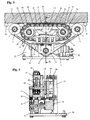
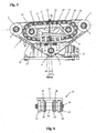
- the in the Figures 1 and 2 in a front and rear view measuring device shown here comprises a belt formed here as an endless belt 1, which is guided around two lying in a plane deflection pulleys 2 and 3 and a staggered third disc 4.
- the two deflecting disks 2 and 3 are rotatably mounted about axes of rotation 5 and 6 on a plate-shaped carrier 7.
- the disc 4 is within an in FIG. 1 recognizable receptacle 8 rotatably mounted about a rotation axis 9.
- the receptacle 8 is biased by two springs 10 mounted on a holder 7 fixed to the bracket 11. By the two springs 10, the receptacle 8 is pressed with the rotatably mounted therein disk 4 away from the holder 7 fixed to the bracket 11 against the inside of the belt 1, so that it is stretched.
- the two deflecting disks 2 and 3 and the disk 4 are designed as toothed disks for positive engagement with the belt 1 embodied here as an endless toothed belt 1 executed.
- the belt arrangement is designed in such a way that the region or run of the belt 1 extending between the two deflecting disks 2 and 3 acts as an abutment 16 for abutment against an in FIG. 3 shown workpiece 15 is used and with its outer side 17 at least partially comes to rest on a surface of the workpiece 15.
- the example as a wooden beam, wood board or the like.
- Performed workpiece 15 rests on a here formed by transport rollers roller conveyor or other suitable workpiece support 18 a plate processing plant or similar woodworking equipment and can be transported for processing by a transport device not shown along the workpiece support.
- the belt 1 is entrained by frictional engagement with the workpiece 15 and can be used to detect the movement of the workpiece 15.
- the belt assembly is in the embodiment shown so part of a measuring device for detecting the movement of the longitudinally moving workpiece 15, in which case the third disc 4 is connected to a rotary encoder or other suitable sensor 19 for detecting the rotational movement of the disc 4.
- detectable sensor 19 could also be attached to one of the deflecting plates 2 and 3.
- the carrier 7 is at an in FIG. 2 shown plate-shaped bracket 20 pivotally mounted such that it is perpendicular to a direction of movement of the belt 1 (in FIG. 5 perpendicular to the plane) pivot axis 21 is rotatable.
- the pivot axis 21 of the carrier 7 is located in a region which extends from a plane 22 formed by the axes of rotation 5 and 6 of the deflection plates 2 and 3 in the direction of the system formed by the belt 1 6.3trums 16.
- the pivot axis 21 is located in the middle between the two deflection disks 2 and 3 on the outer side 17 of the belt 1 formed for contact with the workpiece 15.
- the pivotability of the carrier 7 can be achieved by the carrier 7 is mounted via a convex bearing part 23 in a corresponding concave bearing shell 24.
- FIG. 4 It can be seen that the bearing shell 24 protrudes through an opening 25 of the carrier 7 and is secured to the plate-shaped holder 20.
- a delivery of the Belt 1 in the direction of the workpiece 15 is made possible in the embodiment shown in that the plate-shaped holder 20 is slidably guided via a linear guide on a frame formed from a bottom plate 26 and a bracket 27 and adjustable by a drive.
- the linear guide comprises a guide rail 28 fastened to the console 27 and a carriage 29 which is displaceably guided on the guide rail 28 and which slides in accordance with FIG FIG. 2 is attached to one end of the plate-shaped holder 20.
- the drive includes a hydraulically or pneumatically actuable actuating cylinder 30, whose piston rod is connected via a spring 31 and a retaining plate 32 with the other end of the plate-shaped holder 20.
- the carrier 7 can be raised or lowered relative to the base plate 26 and thus moved toward the workpiece 15 or away therefrom, whereby the contact pressure of the abutment 16 on the workpiece 14 can be changed.
- the contact margin 16 of the belt 1 is pressed by a pressure device 33 against the workpiece 15.
- the pressure device 33 includes a plurality of moving in the transport direction of the belt 1 with this Anyaketti 34, which are part of a guided around two Kettenumlenkiza 35 and 36 endless chain in the embodiment shown.
- the two on the support 7 rotatably mounted Kettenumlenkiza 35 and 36 are designed as gears.
- An horrimile 34 consist of a base body with an upper pressure member 37 and two downwardly projecting legs 38, through the two axes 39 with both sides rotatably mounted rollers 40 for resting on a in the Figures 3 and 5 shown pressure plate 41 run. By sitting on the ends of the axles 39 outer link plate 42, the rollers 40 are held.
- the pressure elements 11 are characterized by in FIG. 3 shown inner link plates 43 connected to the guided over the Kettenumlenkmann 35 and 36 endless chain. Between the inner link plates 43, a sleeve 44 is arranged.
- the pressure elements 34 slide as possible friction and wear on the pressure plate 41.
- the pressure plate 41 arranged between the chain deflection wheels 35 and 36 is designed in such a way that the pressure elements 34 are pressed against the belt 1 during the overflow via the pressure plate 41 and press it against the underside of the workpiece 7.
- the pressure plate 41 has a particularly in FIG. 3 recognizable ramp-shaped course with an inclined in the direction of movement of the pressing elements 34 to the pressing elements 34 towards the front ramp surface 45 and a sloping rear ramp surface 46.
- the measuring device described above is used for measuring the movement of a workpiece on a plate processing plant or a similar woodworking plant.
- the measuring device is integrated in a transport track or other workpiece support of the woodworking system so that the contact amount 16 of the belt 1 is e.g. comes to rest on the underside of resting on the transport path and transported in the longitudinal direction workpiece 15.
- the belt can also come to other side surfaces of the workpiece 15 to the plant. If the workpiece 15 is moved by a transport device, not shown here in the longitudinal direction, the pressed by the pressing elements 34 to the underside of the workpiece 15 belt 1 is taken due to the friction and transmits its movement to the disc 4, to which the sensor 19 for detecting the Rotary movement of the disc 4 is arranged. As a result, the feed movement of the workpiece 15 can be detected and measured. Since the pressure elements 34 move together with the belt 1 and there is no relative movement between pressure elements 34 and belt 1, no sliding friction occurs between the pressure elements 34 and the belt 1.
- the belt assembly could also be used to transport a workpiece, e.g. one or more of the deflection pulleys is driven. At the same time, a measurement of the movement of the workpiece can also be made here.
- a chain or similar tension elements could also be used, which are pressed against the workpiece 15 via the above-described pressing device 33 and pass through the workpiece 15 by means of suitable frictional or positive-locking elements in slip-free connection.
Description
Die Erfindung betrifft eine Messvorrichtung zur Erfassung der Vorschubbewegung eines zu bearbeitenden Werkstücks nach dem Oberbegriff des Anspruchs 1. Die Erfindung betrifft außerdem eine Holzbearbeitungsanlage mit einer solchen Messvorrichtung.The invention relates to a measuring device for detecting the feed movement of a workpiece to be machined according to the preamble of
Eine solche Messvorrichtung ist aus
Eine derartige Messvorrichtung ist aus der
Aus der
Aufgabe der Erfindung ist es, eine Messvorrichtung und eine mit einer solchen Messeinrichtung ausgestattete Holzbearbeitungsanlage zu schaffen, die eine möglichst genaue Erfassung der Vorschubbewegung eines Werkstücks ermöglichen.The object of the invention is to provide a measuring device and equipped with such a measuring device woodworking system, which allow the most accurate detection of the feed movement of a workpiece.
Diese Aufgabe wird durch eine Messeinrichtung mit den Merkmalen des Anspruchs 1 und durch eine Holzbearbeitungsanlage mit den Merkmalen des Anspruchs 12 gelöst. Zweckmäßige Weiterbildungen und vorteilhafte Ausführungsformen der Erfindung sind Gegenstand der Unteransprüche.This object is achieved by a measuring device with the features of
Bei der erfindungsgemäßen Messeinrichtung umfasst die mit dem Riemen bzw. der Kette mitbewegte Andruckeinrichtung mehrere durch Kettenlaschen zu einer Endloskette miteinander verbundene und über mindestens zwei Kettenumlenkräder geführte Andruckelemente. Die beiden in einer Ebene liegenden Kettenumlenkräder sind zweckmäßigerweise in einer Ebene zwischen den beiden Umlenkscheiben des Riemens derart angeordnet, dass die Andruckelemente zur Anlage an der Innenseite des zwischen den beiden Umlenkscheiben angeordneten Anlagetrums des Riemens gelangen. Dadurch dass sich die Andruckelemente mit dem Riemen oder der Kette mitbewegen, kann der Riemen bzw. die Kette zur Erzielung einer schlupffreien Verbindung mit dem Werkstück an das Werkstück angedrückt werden, ohne dass eine Gleitreibung zwischen Andruckelement und dem Riemen bzw. der Kette auftritt. Dadurch kann z.B. die Bewegung eines Werkstücks genau und schlupffrei ermittelt werden. In einer weiteren Ausgestaltung könnte die Andruckeinrichtung aber auch als mitbewegter Riemen ausgeführt sein.In the measuring device according to the invention, the pressing device which moves along with the belt or the chain comprises a plurality of pressure elements connected to one another by link plates to form an endless chain and guided over at least two chain reversing wheels. The two lying in a plane Kettenumlenkräder are suitably arranged in a plane between the two pulleys of the belt such that the pressure elements come to rest on the inside of the arranged between the two deflectors Anlagetrums the belt. The fact that the pressure elements move with the belt or the chain, the belt or the chain can be pressed against the workpiece to achieve a slip-free connection with the workpiece without a sliding friction between the pressure element and the belt or the chain occurs. Thereby, e.g. the movement of a workpiece can be determined accurately and slip-free. In a further embodiment, however, the pressure device could also be designed as a co-moving belt.
Die Schwenkachse des Trägers liegt in einer bevorzugten Ausführung in einem Bereich, der sich von einer durch die Drehachsen der Umlenkscheiben gebildeten Ebene in Richtung eines durch den Riemen bzw. die Kette gebildeten Anlagetrums zur Anlage an dem Werkstück erstreckt. Vorzugsweise ist die Schwenkachse dabei auf der zum Kontakt mit dem Werkstück ausgebildeten Außenseite des durch den Riemen bzw. die Kette gebildeten Anlagetrums in der Mitte zwischen den beiden Umlenkscheiben angeordnet. Dadurch können durch Unebenheiten des Werkstücks bedingte Messfehler besonders wirksam vermieden werden.In a preferred embodiment, the pivot axis of the carrier lies in a region which extends from a plane formed by the axes of rotation of the deflecting disks in the direction of an abutment belt formed by the belt or chain to bear against the workpiece. Preferably, the pivot axis is arranged on the outer side of the contactor formed by the belt or the chain for contact with the workpiece in the middle between the two deflection plates. As a result, measurement errors caused by unevenness of the workpiece can be avoided particularly effectively.
Eine genaue und stabile Lagerung des Trägers kann z.B. dadurch erreicht werden, dass der Träger über ein konvexes Lagerteil in einer dazu korrespondierenden, konkaven Lagerschale gelagert ist. Die Lagerschale kann durch eine Öffnung des Trägers hindurch ragen und an der Halterung befestigt sein.An accurate and stable mounting of the carrier can be achieved, for example, in that the carrier has a convex bearing part in a corresponding, concave bearing shell is stored. The bearing shell can protrude through an opening of the carrier and be attached to the holder.
Eine Verschiebung des Riemens bzw. der Kette in Richtung des Werkstücks bzw. von diesem weg kann dadurch erreicht werden, dass die Halterung über eine Linearführung verschiebbar an einem Gestell geführt und durch einen Antrieb verstellbar ist.A displacement of the belt or the chain in the direction of the workpiece or from this away can be achieved in that the holder is slidably guided via a linear guide on a frame and adjustable by a drive.
Zweckmäßigerweise werden die Andruckelemente durch eine Druckplatte gegen die Innenseite des Riemens gedrückt. Die Druckplatte kann zwischen den Kettenumlenkrädem angeordnet sein und ist derart ausgeführt, dass die Andruckelemente beim Überlauf über die Druckplatte gegen die Innenseite des Riemens gedrückt werden und diesen z.B. an die Unterseite eines Werkstücks anpressen. Hierzu kann die Druckplatte einen rampenförmigen Verlauf aufweisen. Die Druckplatte kann auch um eine horizontale Achse schwenkbar sein. Dadurch können die Andruckelemente auch an unregelmäßige Werkstücke gut angedrückt werden.Conveniently, the pressure elements are pressed by a pressure plate against the inside of the belt. The pressure plate may be disposed between the Kettenumlenkrädem and is designed such that the pressure elements are pressed in the overflow on the pressure plate against the inside of the belt and this example. Press against the underside of a workpiece. For this purpose, the pressure plate may have a ramp-shaped course. The pressure plate can also be pivotable about a horizontal axis. As a result, the pressure elements can be pressed well even on irregular workpieces.
Um eine möglichst geringe Reibung zwischen den Andruckelementen und der Druckplatte zu erreichen, können an den Andruckelementen oder auch an den Verbindungselementen zwischen den Andruckelementen drehbar gelagerte Rollen zur Auflage an der Druckplatte angeordnet sein.In order to achieve the lowest possible friction between the pressure elements and the pressure plate, rotatably mounted rollers can be arranged for resting on the pressure plate on the pressure elements or on the connecting elements between the pressure elements.
In einer besonders zweckmäßigen Ausgestaltung ist der Riemen über zwei in einer Ebene angeordnete Umlenkscheiben eine dazu versetzte dritte Scheibe geführt, wobei die dritte Scheibe durch Federn gegen die Innenseite des Riemens gedrückt wird.In a particularly advantageous embodiment, the belt is guided over two arranged in a plane deflecting a staggered third disc, the third disc is pressed by springs against the inside of the belt.
Die vorstehend beschriebene Messvorrichtung ist vorzugsweise zur Erfassung der Bewegung eines Werkstücks an einer Plattenbearbeitungsanlage, einer Abbundanlage oder einer ähnlichen Holzbearbeitungsanlage einsetzbar. Hierzu wird der Riemen oder die Kette durch die mit diesen mitbewegte Andruckelemente z.B. an die Unterseite eines auf einer Werkstückauflage in Längsrichtung bewegten Werkstücks angedrückt. An mindestens einer der Umlenkscheiben des Riemens kann ein Sensor oder eine andere geeignete Einrichtung zur Erfassung deren Drehbewegung angeordnet sein. Durch Erfassung der Drehbewegung der vom Werkstück über den Riemen bzw. eine Kette angetriebenen Umlenkscheibe kann so die Bewegung des Werkstücks erfasst und schlupffrei gemessen werden. Die Bewegung des Riemens oder der Kette kann aber auch direkt durch andere geeignete Messeinrichtungen erfasst werden. So könnte z.B. auch die Anzahl der an einem geeigneten Detektor vorbeilaufenden Zähne eines Zahnriemens erfasst und zur direkten Messung der Riemenbewegung verwendet werden. Auch andere Messeinrichtungen zur Erfassung der Riemen- oder Kettenbewegung wären geeignet.The measuring device described above is preferably used for detecting the movement of a workpiece on a plate processing plant, a joinery or similar woodworking plant. For this purpose, the belt or the chain is pressed by the moving together with these pressure elements, for example, to the underside of a moving on a workpiece support in the longitudinal direction of the workpiece. On at least one of the deflection pulleys of the belt, a sensor or other suitable means for detecting the rotational movement may be arranged. By detecting the rotational movement of the workpiece over the belt or a chain driven pulley so the movement of the workpiece can be detected and measured without slippage. The movement of the Belt or the chain can also be detected directly by other suitable measuring devices. Thus, for example, the number of teeth of a toothed belt passing by a suitable detector could also be detected and used for direct measurement of the belt movement. Other measuring devices for detecting the belt or chain movement would be suitable.
Weitere Besonderheiten und Vorzüge der Erfindung ergeben sich aus der folgenden Beschreibung eines bevorzugten Ausführungsbeispiels anhand der Zeichnung. Es zeigen:
-
Figur 1 - eine erfindungsgemäße Messvorrichtung in einer Ansicht von vorne;
-
Figur 2 - die Messvorrichtung von
Figur 1 -
Figur 3 - die Messvorrichtung von
Figur 1 -
Figur 4 - eine Schnittansicht entlang der Pfeile A-A von
Figur 4 -
Figur 5 - die Messvorrichtung von
Figur 3 -
Figur 6 - ein Andruckelement in einer Seitenansicht.
- FIG. 1
- a measuring device according to the invention in a view from the front;
- FIG. 2
- the measuring device of
FIG. 1 in a view from behind; - FIG. 3
- the measuring device of
FIG. 1 in a side view; - FIG. 4
- a sectional view taken along the arrows AA of
FIG. 4 and - FIG. 5
- the measuring device of
FIG. 3 in a tilted position and - FIG. 6
- a pressure element in a side view.
Die in den
Die beiden Umlenkscheiben 2 und 3 und die Scheibe 4 sind als Zahnscheiben zum formschlüssigen Eingriff mit dem hier als Endlos-Zahnriemen ausgebildeten Riemen 1 ausgeführt. Die Riemenanordnung ist derart ausgestaltet, dass der zwischen den beiden Umlenkscheiben 2 und 3 verlaufende Bereich bzw. Trum des Riemens 1 als Anlagetrum 16 zur Anlage an einem in
Die Riemenanordnung ist bei dem gezeigten Ausführungsbeispiel also Teil einer Messeinrichtung zur Erfassung der Bewegung des in Längsrichtung bewegten Werkstücks 15, wobei hier die dritte Scheibe 4 mit einem Drehgeber oder einem anderen geeigneten Sensor 19 zur Erfassung der Drehbewegung der Scheibe 4 verbunden ist. Durch Erfassung der Drehbewegung der vom Werkstück 15 über den Riemen 1 angetriebenen Scheibe 4 kann so die Bewegung des Werkstücks 15 erfasst werden. Der in den
Wie besonders aus
In
Die Linearführung umfasst eine an der Konsole 27 befestigte Führungsschiene 28 und einen an der Führungsschiene 28 verschiebbar geführten Schlitten 29, der gemäß
Um eine möglichst schlupffreie Mitnahme des Riemens 1 bei der Bewegung des Werkstücks 7 zu erreichen, wird der Anlagetrum 16 des Riemens 1 durch eine Andruckeinrichtung 33 gegen das Werkstück 15 gedrückt. Die Andruckeinrichtung 33 umfasst mehrere in Transportrichtung des Riemens 1 mit diesem mitbewegte Andruckelemente 34, die bei der gezeigten Ausführung Teil einer um zwei Kettenumlenkräder 35 und 36 geführten Endloskette sind. Bei der gezeigten Ausführung sind die beiden an dem Träger 7 drehbar gelagerten Kettenumlenkräder 35 und 36 als Zahnräder ausgeführt.In order to achieve as slippery as possible entrainment of the
Die in
Durch die an den Achsen 39 beidseitig des Andruckelements 34 angeordneten Rollen 40 gleiten die Andruckelemente 34 möglichst reibungs- und verschleißfrei auf der Druckplatte 41. Die zwischen den Kettenumlenkrädern 35 und 36 angeordnete Druckplatte 41 ist derart ausgeführt, dass die Andruckelemente 34 beim Überlauf über die Druckplatte 41 gegen den Riemen 1 gedrückt werden und diesen an die Unterseite des Werkstücks 7 anpressen. Hierzu weist die Druckplatte 41 einen besonders in
Bei der gezeigten Ausführung wird die vorstehend beschriebene Messvorrichtung zur Messung der Bewegung eines Werkstücks an einer Plattenbearbeitungsanlage oder einer ähnlichen Holzbearbeitungsanlage eingesetzt. Die Messvorrichtung ist in eine Transportbahn oder eine andere Werkstückauflage der Holzbearbeitungsanlage so integriert, dass der Anlagetrum 16 des Riemens 1 z.B. zur Anlage an der Unterseite des auf der Transportbahn aufliegenden und in Längsrichtung transportierten Werkstücks 15 gelangt. Selbstverständlich kann der Riemen auch an anderen Seitenflächen des Werkstücks 15 zur Anlage gelangen. Wird das Werkstück 15 durch eine hier nicht dargestellte Transportvorrichtung in Längsrichtung bewegt, wird der durch die Andrückelemente 34 an die Unterseite des Werkstücks 15 angedrückte Riemen 1 aufgrund der Reibung mitgenommen und überträgt seine Bewegung auf die Scheibe 4, an welcher der Sensor 19 zur Erfassung der Drehbewegung der Scheibe 4 angeordnet ist. Dadurch kann die Vorschubbewegung des Werkstücks 15 erfasst und gemessen werden. Da sich die Andruckelemente 34 zusammen mit dem Riemen 1 bewegen und keine Relativbewegung zwischen Andruckelementen 34 und Riemen 1 erfolgt, tritt keine Gleitreibung zwischen den Andruckelementen 34 und dem Riemen 1 auf.In the embodiment shown, the measuring device described above is used for measuring the movement of a workpiece on a plate processing plant or a similar woodworking plant. The measuring device is integrated in a transport track or other workpiece support of the woodworking system so that the
Die vorstehend beschriebene Messvorrichturig ist nicht auf den ausführlich erläuterten Einsatzzweck beschränkt. So könnte die Riemenanordnung auch zum Transport eines Werkstücks eingesetzt werden, wenn z.B. einer oder mehrere der Umlenkscheiben angetrieben wird. Gleichzeitig kann auch hier eine Messung der Bewegung des Werkstücks erfolgen. Anstelle des Riemens 1 könnte außerdem auch eine Kette oder ähnliche Zugelemente verwendet werden, die über die vorstehend beschriebene Andruckeinrichtung 33 an das Werkstück 15 angedrückt werden und durch geeignete Reib- oder Formschlusselemente in schlupffreie Verbindung mit dem Werkstück 15 gelangen.The measuring device described above is not limited to the purpose described in detail. Thus, the belt assembly could also be used to transport a workpiece, e.g. one or more of the deflection pulleys is driven. At the same time, a measurement of the movement of the workpiece can also be made here. Instead of the
Claims (14)
- Measurement apparatus for the detection of the feed movement of a workpiece (15) that is to be processed and that contains a belt (1) or chain, which is guided on a carrier (17) via deflection disks (2, 3), a pressure device (33), which is moved along with the belt (1) or the chain in its movement direction so as to press the belt (1) or the chain against the workpiece (1), and a sensor (19) to detect the movement of the belt (1) or the chain, wherein the carrier (7) can rotate on a holder (20) around a swivel axis (21) at a right angle to the direction of movement of the belt (1) or the chain, characterised in that the pressure device (33) comprises several pressure elements (34), which are connected with one another by means of chain plates (43) to form an endless chain and which are guided via at least two chain deflection wheels (35, 36).
- Measurement apparatus according to claim 1, characterised in that the swivel axis (21) of the carrier (7) lies in an area that extends from a plane formed by the rotating axes (5, 6) of the deflection disks (2, 3) in the direction of a placement section formed by the belt (1) or the chain for placement on the workpiece (1).
- Measurement apparatus according to claim 2, characterised in that the swivel axis (21) on the outside (17) designed for contact with the workpiece of the placement section (16) formed by the belt (1) or the chain lies in the center between the two deflection disks (2, 3).
- Measurement apparatus according to one of claims 1 to 3, characterised in that the carrier (7) is supported via a convex support part (23) in a concave support shell (24) corresponding to it.
- Measurement apparatus according to claim 4, characterised in that the support shell (24) protrudes through an opening (25) of the carrier (7) and is fastened to the plate-shaped holder (20).
- Measurement apparatus according to on of claims 1 to 5, characterised in that the holder (20) is guided via a linear guide (28, 29) in such a manner that it can be displaced on a frame (26, 27) and can be adjusted by means of a drive (30, 31).
- Measurement apparatus according to claim 6, characterised in that the linear guide (28, 29) comprises a guide track (28), which is fastened to a console (27) of the frame, and a carriage (29), which is guided so it can be displaced on the guide track (28) and on which the holder (20) is fastened.
- Measurement apparatus according to one of claims 6 or 7, characterised in that the drive (30, 31) contains a hydraulically or pneumatically actuatable adjustment cylinder (30), whose piston rod is connected with the holder (20) via a spring (31) and a holder plate (32).
- Measurement apparatus according to Claim 1, characterised in that the chain deflection wheels (35, 36) are located between the deflection disks (2, 3) supported on the carrier (7) so they can rotate.
- Measurement apparatus according to one of claims 1 or 9, characterised in that the pressure elements (34) are guided against the inside of the belt via a pressure plate (41) for the pressing of the pressure elements (34).
- Measurement apparatus according to one of claims 1, 9 or 10, characterised in that on the pressure elements (34) there are rollers (40) located, which are supported so they can rotate.
- Wood processing system with at least one processing unit and a measurement apparatus for the measurement of the feed movement of a wooden workpiece to be processed, characterised in that the measurement apparatus is designed according to one of claims 1 to 11.
- Wood processing system according to claim 12, characterised in that the measurement apparatus is located above and/or below and/or laterally and/or in the feed direction before and/or behind the at least one processing unit.
- Wood processing system according to one of claims 12 or 13, characterised in that the measurement apparatus is integrated into a workpiece support (18) for the workpiece (15).
Applications Claiming Priority (1)
| Application Number | Priority Date | Filing Date | Title |
|---|---|---|---|
| DE102013104241.4A DE102013104241A1 (en) | 2013-04-26 | 2013-04-26 | Measuring device and woodworking plant with such a measuring device |
Publications (2)
| Publication Number | Publication Date |
|---|---|
| EP2796238A1 EP2796238A1 (en) | 2014-10-29 |
| EP2796238B1 true EP2796238B1 (en) | 2016-07-06 |
Family
ID=50343654
Family Applications (1)
| Application Number | Title | Priority Date | Filing Date |
|---|---|---|---|
| EP14160925.5A Active EP2796238B1 (en) | 2013-04-26 | 2014-03-20 | Measuring device and wood-working machine with such a measuring device |
Country Status (7)
| Country | Link |
|---|---|
| US (1) | US9541569B2 (en) |
| EP (1) | EP2796238B1 (en) |
| JP (1) | JP5902224B2 (en) |
| AU (1) | AU2014201886B2 (en) |
| CA (1) | CA2847963C (en) |
| DE (1) | DE102013104241A1 (en) |
| PL (1) | PL2796238T3 (en) |
Families Citing this family (4)
| Publication number | Priority date | Publication date | Assignee | Title |
|---|---|---|---|---|
| US10473237B2 (en) * | 2017-05-09 | 2019-11-12 | Broussard Brothers Inc. | Push rack pipe pusher for floating pipeline installations |
| DE102017120471A1 (en) | 2017-09-06 | 2019-03-07 | Hans Hundegger | Board processing plant |
| CN108772741A (en) * | 2018-06-14 | 2018-11-09 | 浙江昆博机械制造有限公司 | A kind of power control cabinet cabinet process units of size adjustable |
| DE102022122111A1 (en) | 2022-09-01 | 2024-03-07 | Hans Hundegger Beteiligungs Gmbh & Co. Kg | Plate processing plant |
Citations (1)
| Publication number | Priority date | Publication date | Assignee | Title |
|---|---|---|---|---|
| DE102006008657A1 (en) * | 2006-02-24 | 2007-08-30 | Klitsch, Edgar | Circulating link chain for accurate workpiece feed motion, has double toothed gear belt on straight longitudinal piece of link chain having straight link chain pieces on entire length engages into recess of chain slider |
Family Cites Families (15)
| Publication number | Priority date | Publication date | Assignee | Title |
|---|---|---|---|---|
| US3182877A (en) * | 1963-01-07 | 1965-05-11 | Bowen Tools Inc | Apparatus for feeding tubing or other objects |
| JPS471356Y1 (en) * | 1968-07-25 | 1972-01-18 | ||
| FR2128182B1 (en) * | 1971-03-10 | 1975-06-06 | Guilliet Ets | |
| DE2927751A1 (en) * | 1979-07-10 | 1981-01-29 | Gustav Roelle | Measuring lengths of cables, tapes, tubes and foils - using band on rollers with friction-dependent motor control |
| DE3143867A1 (en) | 1981-11-05 | 1983-05-11 | Wolfram 4983 Kirchlengern Sielemann | Apparatus for guiding and displacing bar-shaped and plate-shaped workpieces in machine tools |
| EP0185788B1 (en) * | 1984-12-21 | 1988-08-24 | Audi Ag | Wire-feeding device for an insulated wire cutting and stripping apparatus |
| SE463139B (en) * | 1986-04-11 | 1990-10-15 | Oesa Ab | FEATURING DEVICE FOR ASTAD ACHIEVEMENT OF A LONG-TERM RELATED RELATIONSHIP BETWEEN A TREAD AND THE SELF DEVICE |
| US4776453A (en) * | 1986-04-11 | 1988-10-11 | Harry Major Machine & Tool Co. | Accumulating conveyor |
| US5069440A (en) * | 1990-04-05 | 1991-12-03 | Unisys Corporation | Apparatus and method for automatically and continuously producing a flow of singulated mail flats |
| US5094340A (en) | 1990-11-16 | 1992-03-10 | Otis Engineering Corporation | Gripper blocks for reeled tubing injectors |
| US5775417A (en) | 1997-03-24 | 1998-07-07 | Council; Malcolm N. | Coiled tubing handling apparatus |
| AT413505B (en) * | 2001-03-09 | 2006-03-15 | Sticht Fertigungstech Stiwa | MANUFACTURING SYSTEM FOR MOUNTING AND / OR PROCESSING COMPONENTS TRANSPORTED ON WORKPIECE SUPPLIES |
| CA2414882C (en) | 2002-12-19 | 2010-12-07 | C-Tech Energy Services Inc. | Well string injection system with gripper pads |
| DE202011105077U1 (en) * | 2011-08-27 | 2012-11-28 | Hans Hundegger | Belt or chain arrangement and woodworking plant with such a belt or chain arrangement |
| JP6025622B2 (en) | 2013-03-08 | 2016-11-16 | 東芝テック株式会社 | Ink jet head, ink jet recording apparatus, and method of manufacturing ink jet head |
-
2013
- 2013-04-26 DE DE102013104241.4A patent/DE102013104241A1/en not_active Withdrawn
-
2014
- 2014-03-20 PL PL14160925.5T patent/PL2796238T3/en unknown
- 2014-03-20 EP EP14160925.5A patent/EP2796238B1/en active Active
- 2014-04-02 AU AU2014201886A patent/AU2014201886B2/en active Active
- 2014-04-03 JP JP2014076872A patent/JP5902224B2/en active Active
- 2014-04-03 CA CA2847963A patent/CA2847963C/en active Active
- 2014-04-24 US US14/260,983 patent/US9541569B2/en active Active
Patent Citations (1)
| Publication number | Priority date | Publication date | Assignee | Title |
|---|---|---|---|---|
| DE102006008657A1 (en) * | 2006-02-24 | 2007-08-30 | Klitsch, Edgar | Circulating link chain for accurate workpiece feed motion, has double toothed gear belt on straight longitudinal piece of link chain having straight link chain pieces on entire length engages into recess of chain slider |
Also Published As
| Publication number | Publication date |
|---|---|
| AU2014201886B2 (en) | 2015-10-01 |
| CA2847963C (en) | 2017-11-28 |
| AU2014201886A1 (en) | 2014-11-13 |
| PL2796238T3 (en) | 2016-12-30 |
| CA2847963A1 (en) | 2014-10-26 |
| DE102013104241A1 (en) | 2014-10-30 |
| JP5902224B2 (en) | 2016-04-13 |
| JP2014213447A (en) | 2014-11-17 |
| EP2796238A1 (en) | 2014-10-29 |
| US9541569B2 (en) | 2017-01-10 |
| US20140318242A1 (en) | 2014-10-30 |
Similar Documents
| Publication | Publication Date | Title |
|---|---|---|
| AT405724B (en) | DEVICE FOR MACHINING THE EDGE AREAS OF A GLASS PANEL | |
| EP2565000B1 (en) | Wood-working machine | |
| EP2796238B1 (en) | Measuring device and wood-working machine with such a measuring device | |
| DE102017012078A1 (en) | Mobile support device with at least two support brackets | |
| WO2013064942A1 (en) | Measuring device | |
| DE2110836C3 (en) | Device for transporting book blocks | |
| EP2802441B1 (en) | Wood-working machine and method for the operation thereof | |
| EP0158784A1 (en) | X-Y coordinates positioning device | |
| DE3411452A1 (en) | Workpiece carrier conveyor arrangement | |
| DE202005014860U1 (en) | Device for conveying of workpieces on workpiece carriers has drive shaft of drive provided with cam plate and ratchet carrier with ratchet arm, whereby ratchet arm has mechanical control element tracing cam plate | |
| EP0420018B1 (en) | Rounded cans bodies feeding device for a welding unit | |
| WO2015185615A1 (en) | System and method for measuring a dimension of a workpiece | |
| DE2137008A1 (en) | Method and device for the automatic reading of information carriers on objects | |
| DE2407847C3 (en) | Transport device for flow production | |
| EP2535157A1 (en) | Belt or chain drive | |
| EP1407835A1 (en) | Device for cleaning essentially parallelepipedic articles | |
| DE102016100594B4 (en) | Processing device with touch device | |
| DE19624552C2 (en) | Inspection machine for bottles or the like | |
| DE2255347A1 (en) | METAL COLD SAW | |
| DE102006021466A1 (en) | Transport part e.g. workpiece e.g. toothbrush, holder, transporting device, has positioning devices connected with transport parts for movement independent from belts during concurrently, coupled, friction-locked connection with belts | |
| CH404520A (en) | Apparatus for adjusting a receiving device with respect to an aligned row arrangement of objects lying on a moving conveyor belt | |
| DE940702C (en) | Equipment on roller or chain tables for feeding the sheets to the rollers | |
| EP0038871A2 (en) | Conveyer, especially friction roller conveyer | |
| DE102013010645B3 (en) | A children | |
| DE3311560A1 (en) | Device for transport of longitudinally extended cylindrical test specimens through a test apparatus for non-destructive materials testing |
Legal Events
| Date | Code | Title | Description |
|---|---|---|---|
| PUAI | Public reference made under article 153(3) epc to a published international application that has entered the european phase |
Free format text: ORIGINAL CODE: 0009012 |
|
| 17P | Request for examination filed |
Effective date: 20140320 |
|
| AK | Designated contracting states |
Kind code of ref document: A1 Designated state(s): AL AT BE BG CH CY CZ DE DK EE ES FI FR GB GR HR HU IE IS IT LI LT LU LV MC MK MT NL NO PL PT RO RS SE SI SK SM TR |
|
| AX | Request for extension of the european patent |
Extension state: BA ME |
|
| R17P | Request for examination filed (corrected) |
Effective date: 20150429 |
|
| RBV | Designated contracting states (corrected) |
Designated state(s): AL AT BE BG CH CY CZ DE DK EE ES FI FR GB GR HR HU IE IS IT LI LT LU LV MC MK MT NL NO PL PT RO RS SE SI SK SM TR |
|
| REG | Reference to a national code |
Ref country code: DE Ref legal event code: R079 Ref document number: 502014001033 Country of ref document: DE Free format text: PREVIOUS MAIN CLASS: B23Q0003000000 Ipc: B23Q0007030000 |
|
| RIC1 | Information provided on ipc code assigned before grant |
Ipc: B23Q 17/22 20060101ALI20160120BHEP Ipc: B27C 1/12 20060101ALI20160120BHEP Ipc: B23Q 7/03 20060101AFI20160120BHEP Ipc: G01P 1/04 20060101ALI20160120BHEP |
|
| GRAP | Despatch of communication of intention to grant a patent |
Free format text: ORIGINAL CODE: EPIDOSNIGR1 |
|
| INTG | Intention to grant announced |
Effective date: 20160309 |
|
| GRAS | Grant fee paid |
Free format text: ORIGINAL CODE: EPIDOSNIGR3 |
|
| GRAA | (expected) grant |
Free format text: ORIGINAL CODE: 0009210 |
|
| AK | Designated contracting states |
Kind code of ref document: B1 Designated state(s): AL AT BE BG CH CY CZ DE DK EE ES FI FR GB GR HR HU IE IS IT LI LT LU LV MC MK MT NL NO PL PT RO RS SE SI SK SM TR |
|
| REG | Reference to a national code |
Ref country code: GB Ref legal event code: FG4D Free format text: NOT ENGLISH |
|
| REG | Reference to a national code |
Ref country code: AT Ref legal event code: REF Ref document number: 810359 Country of ref document: AT Kind code of ref document: T Effective date: 20160715 Ref country code: CH Ref legal event code: EP Ref country code: CH Ref legal event code: NV Representative=s name: LUCHS AND PARTNER AG PATENTANWAELTE, CH |
|
| REG | Reference to a national code |
Ref country code: IE Ref legal event code: FG4D Free format text: LANGUAGE OF EP DOCUMENT: GERMAN |
|
| REG | Reference to a national code |
Ref country code: DE Ref legal event code: R096 Ref document number: 502014001033 Country of ref document: DE |
|
| REG | Reference to a national code |
Ref country code: SE Ref legal event code: TRGR |
|
| REG | Reference to a national code |
Ref country code: NL Ref legal event code: MP Effective date: 20160706 |
|
| REG | Reference to a national code |
Ref country code: LT Ref legal event code: MG4D |
|
| PG25 | Lapsed in a contracting state [announced via postgrant information from national office to epo] |
Ref country code: HR Free format text: LAPSE BECAUSE OF FAILURE TO SUBMIT A TRANSLATION OF THE DESCRIPTION OR TO PAY THE FEE WITHIN THE PRESCRIBED TIME-LIMIT Effective date: 20160706 Ref country code: LT Free format text: LAPSE BECAUSE OF FAILURE TO SUBMIT A TRANSLATION OF THE DESCRIPTION OR TO PAY THE FEE WITHIN THE PRESCRIBED TIME-LIMIT Effective date: 20160706 Ref country code: RS Free format text: LAPSE BECAUSE OF FAILURE TO SUBMIT A TRANSLATION OF THE DESCRIPTION OR TO PAY THE FEE WITHIN THE PRESCRIBED TIME-LIMIT Effective date: 20160706 Ref country code: NO Free format text: LAPSE BECAUSE OF FAILURE TO SUBMIT A TRANSLATION OF THE DESCRIPTION OR TO PAY THE FEE WITHIN THE PRESCRIBED TIME-LIMIT Effective date: 20161006 Ref country code: IS Free format text: LAPSE BECAUSE OF FAILURE TO SUBMIT A TRANSLATION OF THE DESCRIPTION OR TO PAY THE FEE WITHIN THE PRESCRIBED TIME-LIMIT Effective date: 20161106 Ref country code: NL Free format text: LAPSE BECAUSE OF FAILURE TO SUBMIT A TRANSLATION OF THE DESCRIPTION OR TO PAY THE FEE WITHIN THE PRESCRIBED TIME-LIMIT Effective date: 20160706 |
|
| REG | Reference to a national code |
Ref country code: FR Ref legal event code: PLFP Year of fee payment: 4 |
|
| PG25 | Lapsed in a contracting state [announced via postgrant information from national office to epo] |
Ref country code: PT Free format text: LAPSE BECAUSE OF FAILURE TO SUBMIT A TRANSLATION OF THE DESCRIPTION OR TO PAY THE FEE WITHIN THE PRESCRIBED TIME-LIMIT Effective date: 20161107 Ref country code: LV Free format text: LAPSE BECAUSE OF FAILURE TO SUBMIT A TRANSLATION OF THE DESCRIPTION OR TO PAY THE FEE WITHIN THE PRESCRIBED TIME-LIMIT Effective date: 20160706 Ref country code: ES Free format text: LAPSE BECAUSE OF FAILURE TO SUBMIT A TRANSLATION OF THE DESCRIPTION OR TO PAY THE FEE WITHIN THE PRESCRIBED TIME-LIMIT Effective date: 20160706 Ref country code: GR Free format text: LAPSE BECAUSE OF FAILURE TO SUBMIT A TRANSLATION OF THE DESCRIPTION OR TO PAY THE FEE WITHIN THE PRESCRIBED TIME-LIMIT Effective date: 20161007 |
|
| REG | Reference to a national code |
Ref country code: DE Ref legal event code: R097 Ref document number: 502014001033 Country of ref document: DE |
|
| PG25 | Lapsed in a contracting state [announced via postgrant information from national office to epo] |
Ref country code: RO Free format text: LAPSE BECAUSE OF FAILURE TO SUBMIT A TRANSLATION OF THE DESCRIPTION OR TO PAY THE FEE WITHIN THE PRESCRIBED TIME-LIMIT Effective date: 20160706 Ref country code: EE Free format text: LAPSE BECAUSE OF FAILURE TO SUBMIT A TRANSLATION OF THE DESCRIPTION OR TO PAY THE FEE WITHIN THE PRESCRIBED TIME-LIMIT Effective date: 20160706 |
|
| PGFP | Annual fee paid to national office [announced via postgrant information from national office to epo] |
Ref country code: FI Payment date: 20170203 Year of fee payment: 4 Ref country code: SE Payment date: 20170320 Year of fee payment: 4 |
|
| PLBE | No opposition filed within time limit |
Free format text: ORIGINAL CODE: 0009261 |
|
| STAA | Information on the status of an ep patent application or granted ep patent |
Free format text: STATUS: NO OPPOSITION FILED WITHIN TIME LIMIT |
|
| PG25 | Lapsed in a contracting state [announced via postgrant information from national office to epo] |
Ref country code: BG Free format text: LAPSE BECAUSE OF FAILURE TO SUBMIT A TRANSLATION OF THE DESCRIPTION OR TO PAY THE FEE WITHIN THE PRESCRIBED TIME-LIMIT Effective date: 20161006 Ref country code: SM Free format text: LAPSE BECAUSE OF FAILURE TO SUBMIT A TRANSLATION OF THE DESCRIPTION OR TO PAY THE FEE WITHIN THE PRESCRIBED TIME-LIMIT Effective date: 20160706 Ref country code: CZ Free format text: LAPSE BECAUSE OF FAILURE TO SUBMIT A TRANSLATION OF THE DESCRIPTION OR TO PAY THE FEE WITHIN THE PRESCRIBED TIME-LIMIT Effective date: 20160706 Ref country code: DK Free format text: LAPSE BECAUSE OF FAILURE TO SUBMIT A TRANSLATION OF THE DESCRIPTION OR TO PAY THE FEE WITHIN THE PRESCRIBED TIME-LIMIT Effective date: 20160706 Ref country code: SK Free format text: LAPSE BECAUSE OF FAILURE TO SUBMIT A TRANSLATION OF THE DESCRIPTION OR TO PAY THE FEE WITHIN THE PRESCRIBED TIME-LIMIT Effective date: 20160706 |
|
| PGFP | Annual fee paid to national office [announced via postgrant information from national office to epo] |
Ref country code: PL Payment date: 20170127 Year of fee payment: 4 |
|
| 26N | No opposition filed |
Effective date: 20170407 |
|
| PG25 | Lapsed in a contracting state [announced via postgrant information from national office to epo] |
Ref country code: SI Free format text: LAPSE BECAUSE OF FAILURE TO SUBMIT A TRANSLATION OF THE DESCRIPTION OR TO PAY THE FEE WITHIN THE PRESCRIBED TIME-LIMIT Effective date: 20160706 |
|
| PG25 | Lapsed in a contracting state [announced via postgrant information from national office to epo] |
Ref country code: MC Free format text: LAPSE BECAUSE OF FAILURE TO SUBMIT A TRANSLATION OF THE DESCRIPTION OR TO PAY THE FEE WITHIN THE PRESCRIBED TIME-LIMIT Effective date: 20160706 |
|
| REG | Reference to a national code |
Ref country code: IE Ref legal event code: MM4A |
|
| PG25 | Lapsed in a contracting state [announced via postgrant information from national office to epo] |
Ref country code: LU Free format text: LAPSE BECAUSE OF NON-PAYMENT OF DUE FEES Effective date: 20170320 |
|
| REG | Reference to a national code |
Ref country code: FR Ref legal event code: PLFP Year of fee payment: 5 |
|
| PG25 | Lapsed in a contracting state [announced via postgrant information from national office to epo] |
Ref country code: IE Free format text: LAPSE BECAUSE OF NON-PAYMENT OF DUE FEES Effective date: 20170320 |
|
| REG | Reference to a national code |
Ref country code: BE Ref legal event code: MM Effective date: 20170331 |
|
| PG25 | Lapsed in a contracting state [announced via postgrant information from national office to epo] |
Ref country code: BE Free format text: LAPSE BECAUSE OF NON-PAYMENT OF DUE FEES Effective date: 20170331 |
|
| PG25 | Lapsed in a contracting state [announced via postgrant information from national office to epo] |
Ref country code: MT Free format text: LAPSE BECAUSE OF FAILURE TO SUBMIT A TRANSLATION OF THE DESCRIPTION OR TO PAY THE FEE WITHIN THE PRESCRIBED TIME-LIMIT Effective date: 20160706 |
|
| PG25 | Lapsed in a contracting state [announced via postgrant information from national office to epo] |
Ref country code: SE Free format text: LAPSE BECAUSE OF NON-PAYMENT OF DUE FEES Effective date: 20180321 Ref country code: AL Free format text: LAPSE BECAUSE OF FAILURE TO SUBMIT A TRANSLATION OF THE DESCRIPTION OR TO PAY THE FEE WITHIN THE PRESCRIBED TIME-LIMIT Effective date: 20160706 Ref country code: FI Free format text: LAPSE BECAUSE OF NON-PAYMENT OF DUE FEES Effective date: 20180320 |
|
| GBPC | Gb: european patent ceased through non-payment of renewal fee |
Effective date: 20180320 |
|
| PG25 | Lapsed in a contracting state [announced via postgrant information from national office to epo] |
Ref country code: GB Free format text: LAPSE BECAUSE OF NON-PAYMENT OF DUE FEES Effective date: 20180320 |
|
| PG25 | Lapsed in a contracting state [announced via postgrant information from national office to epo] |
Ref country code: HU Free format text: LAPSE BECAUSE OF FAILURE TO SUBMIT A TRANSLATION OF THE DESCRIPTION OR TO PAY THE FEE WITHIN THE PRESCRIBED TIME-LIMIT; INVALID AB INITIO Effective date: 20140320 |
|
| PG25 | Lapsed in a contracting state [announced via postgrant information from national office to epo] |
Ref country code: CY Free format text: LAPSE BECAUSE OF FAILURE TO SUBMIT A TRANSLATION OF THE DESCRIPTION OR TO PAY THE FEE WITHIN THE PRESCRIBED TIME-LIMIT Effective date: 20160706 |
|
| PG25 | Lapsed in a contracting state [announced via postgrant information from national office to epo] |
Ref country code: PL Free format text: LAPSE BECAUSE OF NON-PAYMENT OF DUE FEES Effective date: 20180320 Ref country code: MK Free format text: LAPSE BECAUSE OF FAILURE TO SUBMIT A TRANSLATION OF THE DESCRIPTION OR TO PAY THE FEE WITHIN THE PRESCRIBED TIME-LIMIT Effective date: 20160706 |
|
| PG25 | Lapsed in a contracting state [announced via postgrant information from national office to epo] |
Ref country code: TR Free format text: LAPSE BECAUSE OF FAILURE TO SUBMIT A TRANSLATION OF THE DESCRIPTION OR TO PAY THE FEE WITHIN THE PRESCRIBED TIME-LIMIT Effective date: 20160706 |
|
| PGFP | Annual fee paid to national office [announced via postgrant information from national office to epo] |
Ref country code: FR Payment date: 20230320 Year of fee payment: 10 Ref country code: AT Payment date: 20230317 Year of fee payment: 10 |
|
| PGFP | Annual fee paid to national office [announced via postgrant information from national office to epo] |
Ref country code: IT Payment date: 20230331 Year of fee payment: 10 Ref country code: DE Payment date: 20230505 Year of fee payment: 10 Ref country code: CH Payment date: 20230402 Year of fee payment: 10 |
|
| REG | Reference to a national code |
Ref country code: DE Ref legal event code: R081 Ref document number: 502014001033 Country of ref document: DE Owner name: HANS HUNDEGGER BETEILIGUNGS GMBH & CO. KG, DE Free format text: FORMER OWNER: HUNDEGGER, HANS, 87749 HAWANGEN, DE |
|
| REG | Reference to a national code |
Ref country code: DE Ref legal event code: R081 Ref document number: 502014001033 Country of ref document: DE Owner name: HANS HUNDEGGER BETEILIGUNGS GMBH & CO. KG, DE Free format text: FORMER OWNER: HANS HUNDEGGER BETEILIGUNGS GMBH & CO. KG, 87749 HAWANGEN, DE |