EP2792805A1 - Élément de mur consistant en éléments prèfabriqués - Google Patents
Élément de mur consistant en éléments prèfabriqués Download PDFInfo
- Publication number
- EP2792805A1 EP2792805A1 EP20140450015 EP14450015A EP2792805A1 EP 2792805 A1 EP2792805 A1 EP 2792805A1 EP 20140450015 EP20140450015 EP 20140450015 EP 14450015 A EP14450015 A EP 14450015A EP 2792805 A1 EP2792805 A1 EP 2792805A1
- Authority
- EP
- European Patent Office
- Prior art keywords
- reinforcing elements
- elements
- directional
- positionable
- semi
- Prior art date
- Legal status (The legal status is an assumption and is not a legal conclusion. Google has not performed a legal analysis and makes no representation as to the accuracy of the status listed.)
- Granted
Links
Images


Classifications
-
- E—FIXED CONSTRUCTIONS
- E04—BUILDING
- E04B—GENERAL BUILDING CONSTRUCTIONS; WALLS, e.g. PARTITIONS; ROOFS; FLOORS; CEILINGS; INSULATION OR OTHER PROTECTION OF BUILDINGS
- E04B2/00—Walls, e.g. partitions, for buildings; Wall construction with regard to insulation; Connections specially adapted to walls
- E04B2/84—Walls made by casting, pouring, or tamping in situ
- E04B2/86—Walls made by casting, pouring, or tamping in situ made in permanent forms
- E04B2/8611—Walls made by casting, pouring, or tamping in situ made in permanent forms with spacers being embedded in at least one form leaf
- E04B2/8617—Walls made by casting, pouring, or tamping in situ made in permanent forms with spacers being embedded in at least one form leaf with spacers being embedded in both form leaves
-
- E—FIXED CONSTRUCTIONS
- E04—BUILDING
- E04B—GENERAL BUILDING CONSTRUCTIONS; WALLS, e.g. PARTITIONS; ROOFS; FLOORS; CEILINGS; INSULATION OR OTHER PROTECTION OF BUILDINGS
- E04B2/00—Walls, e.g. partitions, for buildings; Wall construction with regard to insulation; Connections specially adapted to walls
- E04B2/02—Walls, e.g. partitions, for buildings; Wall construction with regard to insulation; Connections specially adapted to walls built-up from layers of building elements
- E04B2/28—Walls having cavities between, but not in, the elements; Walls of elements each consisting of two or more parts kept in distance by means of spacers, all parts being solid
- E04B2/30—Walls having cavities between, but not in, the elements; Walls of elements each consisting of two or more parts kept in distance by means of spacers, all parts being solid using elements having specially designed means for stabilising the position; Spacers for cavity walls
- E04B2/32—Walls having cavities between, but not in, the elements; Walls of elements each consisting of two or more parts kept in distance by means of spacers, all parts being solid using elements having specially designed means for stabilising the position; Spacers for cavity walls by interlocking of projections or inserts with indentations, e.g. of tongues, grooves, dovetails
-
- E—FIXED CONSTRUCTIONS
- E04—BUILDING
- E04B—GENERAL BUILDING CONSTRUCTIONS; WALLS, e.g. PARTITIONS; ROOFS; FLOORS; CEILINGS; INSULATION OR OTHER PROTECTION OF BUILDINGS
- E04B1/00—Constructions in general; Structures which are not restricted either to walls, e.g. partitions, or floors or ceilings or roofs
- E04B1/38—Connections for building structures in general
- E04B1/61—Connections for building structures in general of slab-shaped building elements with each other
-
- E—FIXED CONSTRUCTIONS
- E04—BUILDING
- E04B—GENERAL BUILDING CONSTRUCTIONS; WALLS, e.g. PARTITIONS; ROOFS; FLOORS; CEILINGS; INSULATION OR OTHER PROTECTION OF BUILDINGS
- E04B2/00—Walls, e.g. partitions, for buildings; Wall construction with regard to insulation; Connections specially adapted to walls
- E04B2/84—Walls made by casting, pouring, or tamping in situ
- E04B2/86—Walls made by casting, pouring, or tamping in situ made in permanent forms
-
- E—FIXED CONSTRUCTIONS
- E04—BUILDING
- E04C—STRUCTURAL ELEMENTS; BUILDING MATERIALS
- E04C5/00—Reinforcing elements, e.g. for concrete; Auxiliary elements therefor
- E04C5/16—Auxiliary parts for reinforcements, e.g. connectors, spacers, stirrups
- E04C5/168—Spacers connecting parts for reinforcements and spacing the reinforcements from the form
-
- E—FIXED CONSTRUCTIONS
- E04—BUILDING
- E04B—GENERAL BUILDING CONSTRUCTIONS; WALLS, e.g. PARTITIONS; ROOFS; FLOORS; CEILINGS; INSULATION OR OTHER PROTECTION OF BUILDINGS
- E04B2/00—Walls, e.g. partitions, for buildings; Wall construction with regard to insulation; Connections specially adapted to walls
- E04B2/84—Walls made by casting, pouring, or tamping in situ
- E04B2/86—Walls made by casting, pouring, or tamping in situ made in permanent forms
- E04B2002/867—Corner details
Definitions
- the present invention relates to a building consisting of several assembled with joint semi-finished components according to the preamble of claim 1.
- the structure is constructed in a dry construction from plates, which are spaced apart from each other and form a cavity between them, wherein the plates are connected to each other at at least two opposite side edges by webs. There are provided support pillars, which are included hidden in overlaps of the plates. In the cavities between the plates can be subsequently introduce insulation and Dämmein accounts.
- the static strength of these structures made of plates should be extremely high.
- the buildings constructed from this should be largely earthquake-proof and only slightly in danger of collapse. This should also contribute to the low weight.
- Object of the present invention is to provide a building, which has a higher strength with economically reasonable effort, as with the known measures of the prior art.
- a building is advantageous if it consists of several joined together with shock semi-finished components consisting of wall panels are formed, which are spaced apart by means of connecting or stabilizing elements and extend substantially in parallel planes to each other, the interstices thus formed are filled with a curable casting composition, and each forming a joint at the junction, and in which the connection or Stabilizing elements are formed by rod-shaped and / or flat spacers which extend substantially perpendicular to the planes of the wall panels, and in which at least the stabilizing elements in the region of the joint interact with positionable, multi-directional reinforcing elements, wherein the multi-directional reinforcing elements run in planes which are substantially perpendicular to the planes of the wall panels.
- the stabilizing elements are realized by rod-shaped and / or planar composite components, which interact with the positionable multi-directional reinforcement elements.
- a building has advantages when the positionable multi-directional reinforcing elements are formed by baskets or by brackets. Whereby it is particularly favorable if the positionable multi-directional reinforcement elements are arranged to be displaceable and / or tiltable.
- a building can be designed particularly advantageous if the positionable multidirectional reinforcing elements cooperate with other reinforcing elements, wherein the other reinforcing elements connected to stabilizing elements and / or are firmly anchored in the wall panels.
- a building according to the invention is extremely stable when a statically required overlap length is created by the interaction of the stabilizing elements and / or the further reinforcing elements with the positionable multi-directional reinforcing elements over the impact.
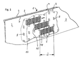
- Fig. 1 is a highly schematic part of a building 1 shown, which consists in the illustrated embodiment of two semi-finished components 2 and 3, which are joined together with a shock 4.
- a building according to the invention may also consist of more than two semi-finished components and in addition to the semi-finished components also have differently shaped components that may be finished parts, semi-finished parts or locally manufactured components.
- At the joint 4 creates a joint 5, which can remain unprocessed in the ideal case 1 in the ideal case.
- the two semi-finished components 2 and 3 are each formed of wall plates 6 and 7, which are spaced apart by means of stabilizing elements 8.
- the wall panels 6 and 7 extend in two mutually parallel planes and thus form a gap 9, which can be filled with hardenable casting compound, for example concrete.
- the stabilizing elements 8 are formed, for example, as a flat structure with a meandering or wavy cross section. As will be shown and described in the following embodiments, other stabilizing elements, such as rod-shaped stabilizing elements are advantageously used, but they must fulfill the purpose to fix the wall plates 6 and 7 stable in their parallel distance and spatially positioning of Modiretationalen reinforcement elements enable.
- multi-directional reinforcing elements is used in the present subject matter of the invention to make it clear that the reinforcing elements expand in several (at least two) directions. This term is intended to distinguish the objects so designated from the common term “multi-dimensional” because every object used in construction practice is, physically considered, “multi-dimensional”. A simple rod is inevitably “multidimensional,” because as a physical body it is “multidimensional,” but it extends in one direction only, so by definition it is “unidirectional.” By definition, the "multi-directional" reinforcing elements used according to the invention expand into a plurality of directions (directions).
- the space 9 are multi-directional reinforcing elements in the form of baskets 10 which are arranged as prefabricated assemblies in the space 9 longitudinally displaceable. They slide on the flat, wave-shaped stabilizing elements 8, by which they are largely fixed in their position within the interstices 9 to their horizontal displaceability.
- the baskets 10 are shifted in the longitudinal direction so far that they span the joint 5 in the area of the joint 4 and create a sufficient Studentsgreifungsdorf Ü required for the stability of the structure 1.
- the gap 9 can be poured with in-situ concrete. It is understood that instead of in-situ concrete any other hardening mass can be filled in the interspaces 9.
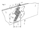
- Fig. 2 an embodiment of the invention is shown, which is a variant of the embodiment according to Fig. 1 represents.
- three-directional baskets 10 are slid obliquely into the interstices 9 of the wall panels 6 and 7 in the area of the impact.
- the stabilizing elements 8 are arranged so that open spaces for insertion of the three-directional baskets 10 result.
- the oblique insertion of the baskets 10 can be done manually or mechanically - ie actively - but it can also be used gravity, with their Help the baskets 10 slide into their final position.
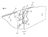
- Fig. 3 is shown a further variant of the invention.
- the assembled semi-finished components 2 and 3 substantially correspond to those already known to the Fig. 1 and 2 have been described.
- the stabilizing elements 8 are assigned permanently to multi-directional reinforcing elements in the form of bidirectional brackets 11, the brackets 11 spanning in two directions a plane perpendicular to the planes in which the wall panels 6 and 7 extend.
- the brackets 11 and 12 are referred to as two-directional reinforcing elements, whereas the baskets 10 described above extend in a further direction and are therefore referred to as three-directional reinforcing elements.
- the two-directional stirrups 11 cooperate with the stabilizing elements 8 and are preferably fastened to them.
- More bidirectional reinforcing elements in the form of positionable brackets 12 are introduced into the space 9 of the other semi-finished component 3 and there shifted in the direction of the first semi-finished component 2 and optionally tilted until the positionable bracket 12 with the rigid brackets 11 in the other half finished Component 2 cooperate and produce in this way the required overlap length Ü.
- Fig. 4 is the end position of the positioned in the manner described above bracket 12 within the gap 9 illustrated.
- the positionable bracket 12 and connected to the stabilizing elements 8 bracket 11 are with a predetermined overlap each other. In this position, they are fixed with split pins 13, which are arranged in the region of the joint 4 within the intermediate space 9 and cooperate for reinforcement with the brackets 11 and 12.
- Fig. 5 is another variant of the subject invention shown.
- rigidly mounted bracket 11 and positionable bracket 12 are shown.
- the peculiarity of the current embodiment is that the rigidly mounted bracket 11 were already cast in the manufacture of the semi-finished component 2 together with the stabilizing elements 8 in the wall panels 6 and 7. They are therefore "invisible" which is to be illustrated by the dashed representation in the left half of the figure.
- the bracket 11 are schematically visible.
- the positionable bracket 12 are introduced in the same manner in the gap 9 as to the embodiments of the Fig. 3 and 4 has already been explained.
- Cotter pins 13 also provide in this variant of the invention the reinforcement connection of both types of brackets, so that a sufficient reinforcement and overlapping length Ü is ensured in the region of the joint 4.
- Fig. 6 illustrates a detail of a building 1, in which a corner of the building 1 is shown.
- Two semi-finished components 2 and 3 have been assembled on the construction site to form a corner joint.
- the semi-finished components 2 and 3 are formed in a known manner by two wall plates 6 and 7 respectively.
- the mutually parallel wall plates 6 and 7 are connected to each other by stabilizing elements 8.
- the flat, wave-shaped stabilizing elements 8 can be formed by rod-shaped stabilizing elements 14.
- the overlapping length required for stability is generated by means of positionable brackets 12 in the intermediate space 9 of the semi-finished components 2 and 3.
- the positionable stirrups 12 are overlapped by being inserted and tilted in the area of impact 4 of the corner and can be fixed by means of splints 13, as shown in FIG Fig. 7 - which shows an advanced assembly phase - is shown.
- FIG. 8 and 9 Another embodiment of the invention is shown, in which a three-directional basket is used as a reinforcing element, which is made of horizontal brackets 16 and vertical bars 17.
- a three-directional basket is used as a reinforcing element, which is made of horizontal brackets 16 and vertical bars 17.
- stabilizing elements In the embodiments described, plate-like or wave-shaped shapes have always been represented and described as stabilizing elements.
- the stabilizing elements can also have other shapes, for example a rod shape, or can be used in different forms of stabilizing elements or arranged in groups.
Landscapes
- Engineering & Computer Science (AREA)
- Architecture (AREA)
- Civil Engineering (AREA)
- Structural Engineering (AREA)
- Physics & Mathematics (AREA)
- Electromagnetism (AREA)
- Conveying And Assembling Of Building Elements In Situ (AREA)
- Reinforcement Elements For Buildings (AREA)
- Joining Of Building Structures In Genera (AREA)
Applications Claiming Priority (1)
| Application Number | Priority Date | Filing Date | Title |
|---|---|---|---|
| ATA308/2013A AT514300B1 (de) | 2013-04-15 | 2013-04-15 | Bauwerk |
Publications (2)
| Publication Number | Publication Date |
|---|---|
| EP2792805A1 true EP2792805A1 (fr) | 2014-10-22 |
| EP2792805B1 EP2792805B1 (fr) | 2019-09-18 |
Family
ID=50549275
Family Applications (1)
| Application Number | Title | Priority Date | Filing Date |
|---|---|---|---|
| EP14450015.4A Active EP2792805B1 (fr) | 2013-04-15 | 2014-04-14 | Élément de mur consistant en éléments prèfabriqués |
Country Status (2)
| Country | Link |
|---|---|
| EP (1) | EP2792805B1 (fr) |
| AT (1) | AT514300B1 (fr) |
Cited By (1)
| Publication number | Priority date | Publication date | Assignee | Title |
|---|---|---|---|---|
| GB2526533A (en) * | 2014-05-09 | 2015-12-02 | Charcon Ltd | Method and apparatus for rebar tying |
Families Citing this family (2)
| Publication number | Priority date | Publication date | Assignee | Title |
|---|---|---|---|---|
| US11248383B2 (en) | 2018-09-21 | 2022-02-15 | Cooper E. Stewart | Insulating concrete form apparatus |
| EP4253693A1 (fr) | 2022-03-29 | 2023-10-04 | Georg Weidner | Entretoise |
Citations (5)
| Publication number | Priority date | Publication date | Assignee | Title |
|---|---|---|---|---|
| EP1146179A2 (fr) * | 2000-04-10 | 2001-10-17 | Angelo Candiracci | Panneau de construction à coffrage pré-armé |
| US20050155306A1 (en) * | 2004-01-21 | 2005-07-21 | Jeffrey Childres | Joining clip for insulated concrete forms |
| DE102007014366A1 (de) * | 2007-03-26 | 2008-10-02 | Gerhard Maier | Bewehrungsvorrichtung für Fertigbau-Teile |
| EP2410100A1 (fr) * | 2010-07-19 | 2012-01-25 | Fehr | Mur à coffrage intégré avec armature de liaison |
| EP2495375A1 (fr) * | 2011-03-02 | 2012-09-05 | H&H Technologies | Mur à coffrage intégré avec élément mobile de liaison pivotant |
Family Cites Families (4)
| Publication number | Priority date | Publication date | Assignee | Title |
|---|---|---|---|---|
| DE29902384U1 (de) * | 1999-02-11 | 2000-07-20 | Rojek Richard | Bewehrungsvorrichtung |
| FR2942824B1 (fr) * | 2009-03-09 | 2016-07-01 | Fehr | Mur a coffrage integre avec armature de liaison |
| CN201649354U (zh) * | 2009-12-18 | 2010-11-24 | 安徽建筑工业学院 | 具有“一”型连接构件的抗震叠合板式剪力墙 |
| FR2965829B1 (fr) * | 2010-10-07 | 2012-10-12 | Fehr Groupe | Mur a coffrage perdu avec cablette de liaison. |
-
2013
- 2013-04-15 AT ATA308/2013A patent/AT514300B1/de not_active IP Right Cessation
-
2014
- 2014-04-14 EP EP14450015.4A patent/EP2792805B1/fr active Active
Patent Citations (5)
| Publication number | Priority date | Publication date | Assignee | Title |
|---|---|---|---|---|
| EP1146179A2 (fr) * | 2000-04-10 | 2001-10-17 | Angelo Candiracci | Panneau de construction à coffrage pré-armé |
| US20050155306A1 (en) * | 2004-01-21 | 2005-07-21 | Jeffrey Childres | Joining clip for insulated concrete forms |
| DE102007014366A1 (de) * | 2007-03-26 | 2008-10-02 | Gerhard Maier | Bewehrungsvorrichtung für Fertigbau-Teile |
| EP2410100A1 (fr) * | 2010-07-19 | 2012-01-25 | Fehr | Mur à coffrage intégré avec armature de liaison |
| EP2495375A1 (fr) * | 2011-03-02 | 2012-09-05 | H&H Technologies | Mur à coffrage intégré avec élément mobile de liaison pivotant |
Cited By (1)
| Publication number | Priority date | Publication date | Assignee | Title |
|---|---|---|---|---|
| GB2526533A (en) * | 2014-05-09 | 2015-12-02 | Charcon Ltd | Method and apparatus for rebar tying |
Also Published As
| Publication number | Publication date |
|---|---|
| EP2792805B1 (fr) | 2019-09-18 |
| AT514300A1 (de) | 2014-11-15 |
| AT514300B1 (de) | 2015-10-15 |
Similar Documents
| Publication | Publication Date | Title |
|---|---|---|
| DE3303190C2 (de) | Bausatz zur Erstellung mobiler Bauten, insbesondere für Messe- und Ausstellungsbauten | |
| WO2007068267A1 (fr) | Element de construction en bois pour construire des parois de batiments | |
| EP2792805B1 (fr) | Élément de mur consistant en éléments prèfabriqués | |
| DE102012217689A1 (de) | Wandschalung und Wandschalungssystem | |
| EP1783293B1 (fr) | Corps isolant renforcé pour élément de mur préfabriqué isolant thermique et élément de mur préfabriqué et méthode de fabrication | |
| EP2816168B1 (fr) | Pierre de coffrage destinée à la liaison avec un revêtement en béton | |
| EP3363968A1 (fr) | Raccord asismique d'un ouvrage à double paroi sur une structure de cadre | |
| EP3299524B1 (fr) | Mur en elements prefabriques et son procede de fabrication | |
| WO2020254255A1 (fr) | Système de paroi | |
| EP2276898B1 (fr) | Pièce de montage préfabriquée possédant un dispositif de stabilisation | |
| EP1959069B1 (fr) | Corps d'isolation sans joint pour une paroi d'extrémité calorifugée et paroi d'extrémité tout comme son procédé de fabrication | |
| DE877488C (de) | Verfahren zur Herstellung von zweischaligen Waenden aus Bauplatten und Bauplatte, insbesondere Leichtbauplatte, hierfuer | |
| EP1592852A1 (fr) | Corps de coffrage perdu | |
| DE2020381C3 (de) | Kühlturm mit einer mehrere Geschosse umfassenden räumlichen Tragkonstruktion | |
| EP2937481B1 (fr) | Élément de construction à isolation thermique | |
| DE102020117356B3 (de) | Elementesatz zur Herstellung eines Streifenfundaments mit wenigstens einer Fundamentecke und Verfahren zur Herstellung einer Schalung für ein Streifenfundament mit wenigstens einer Fundamentecke | |
| EP1767715A2 (fr) | Mur en paves de verre | |
| DE102017120254A1 (de) | Winkelelement und Laibungsverkleidung mit einem Winkelelement | |
| AT515973B1 (de) | Erdbeben-Bügelbewehrung | |
| DE2351786A1 (de) | Bauwerk und verfahren zu dessen herstellung | |
| EP3153635B1 (fr) | Composant a isolation thermique | |
| DE202020103812U1 (de) | Elementesatz zur Herstellung eines Streifenfundaments mit wenigstens einer Fundamentecke | |
| AT324650B (de) | Plattenförmiges bauelement und wand aus einer anzahl solcher bauelemente | |
| EP2175079A2 (fr) | Procédé de formation d'une armature d'angle résistante à la flexion pour la construction en béton armé, élément d'armature et armature d'angle résistante à la flexion | |
| DE2142188A1 (de) | Verfahren zum Herstellen von Rohbauwerken und Wandbauteile für derartige Bauwerke |
Legal Events
| Date | Code | Title | Description |
|---|---|---|---|
| PUAI | Public reference made under article 153(3) epc to a published international application that has entered the european phase |
Free format text: ORIGINAL CODE: 0009012 |
|
| 17P | Request for examination filed |
Effective date: 20140414 |
|
| AK | Designated contracting states |
Kind code of ref document: A1 Designated state(s): AL AT BE BG CH CY CZ DE DK EE ES FI FR GB GR HR HU IE IS IT LI LT LU LV MC MK MT NL NO PL PT RO RS SE SI SK SM TR |
|
| AX | Request for extension of the european patent |
Extension state: BA ME |
|
| R17P | Request for examination filed (corrected) |
Effective date: 20150422 |
|
| RBV | Designated contracting states (corrected) |
Designated state(s): AL AT BE BG CH CY CZ DE DK EE ES FI FR GB GR HR HU IE IS IT LI LT LU LV MC MK MT NL NO PL PT RO RS SE SI SK SM TR |
|
| STAA | Information on the status of an ep patent application or granted ep patent |
Free format text: STATUS: EXAMINATION IS IN PROGRESS |
|
| 17Q | First examination report despatched |
Effective date: 20180313 |
|
| REG | Reference to a national code |
Ref country code: DE Ref legal event code: R079 Ref document number: 502014012666 Country of ref document: DE Free format text: PREVIOUS MAIN CLASS: E04B0002860000 Ipc: E04C0005160000 |
|
| GRAP | Despatch of communication of intention to grant a patent |
Free format text: ORIGINAL CODE: EPIDOSNIGR1 |
|
| STAA | Information on the status of an ep patent application or granted ep patent |
Free format text: STATUS: GRANT OF PATENT IS INTENDED |
|
| RIC1 | Information provided on ipc code assigned before grant |
Ipc: E04C 5/16 20060101AFI20190328BHEP Ipc: E04B 2/86 20060101ALI20190328BHEP |
|
| INTG | Intention to grant announced |
Effective date: 20190415 |
|
| GRAS | Grant fee paid |
Free format text: ORIGINAL CODE: EPIDOSNIGR3 |
|
| GRAA | (expected) grant |
Free format text: ORIGINAL CODE: 0009210 |
|
| STAA | Information on the status of an ep patent application or granted ep patent |
Free format text: STATUS: THE PATENT HAS BEEN GRANTED |
|
| AK | Designated contracting states |
Kind code of ref document: B1 Designated state(s): AL AT BE BG CH CY CZ DE DK EE ES FI FR GB GR HR HU IE IS IT LI LT LU LV MC MK MT NL NO PL PT RO RS SE SI SK SM TR |
|
| REG | Reference to a national code |
Ref country code: GB Ref legal event code: FG4D Free format text: NOT ENGLISH |
|
| REG | Reference to a national code |
Ref country code: CH Ref legal event code: EP |
|
| REG | Reference to a national code |
Ref country code: DE Ref legal event code: R096 Ref document number: 502014012666 Country of ref document: DE |
|
| REG | Reference to a national code |
Ref country code: CH Ref legal event code: NV Representative=s name: BOVARD AG PATENT- UND MARKENANWAELTE, CH Ref country code: AT Ref legal event code: REF Ref document number: 1181470 Country of ref document: AT Kind code of ref document: T Effective date: 20191015 |
|
| REG | Reference to a national code |
Ref country code: IE Ref legal event code: FG4D Free format text: LANGUAGE OF EP DOCUMENT: GERMAN |
|
| REG | Reference to a national code |
Ref country code: NL Ref legal event code: MP Effective date: 20190918 |
|
| PG25 | Lapsed in a contracting state [announced via postgrant information from national office to epo] |
Ref country code: FI Free format text: LAPSE BECAUSE OF FAILURE TO SUBMIT A TRANSLATION OF THE DESCRIPTION OR TO PAY THE FEE WITHIN THE PRESCRIBED TIME-LIMIT Effective date: 20190918 Ref country code: LT Free format text: LAPSE BECAUSE OF FAILURE TO SUBMIT A TRANSLATION OF THE DESCRIPTION OR TO PAY THE FEE WITHIN THE PRESCRIBED TIME-LIMIT Effective date: 20190918 Ref country code: BG Free format text: LAPSE BECAUSE OF FAILURE TO SUBMIT A TRANSLATION OF THE DESCRIPTION OR TO PAY THE FEE WITHIN THE PRESCRIBED TIME-LIMIT Effective date: 20191218 Ref country code: NO Free format text: LAPSE BECAUSE OF FAILURE TO SUBMIT A TRANSLATION OF THE DESCRIPTION OR TO PAY THE FEE WITHIN THE PRESCRIBED TIME-LIMIT Effective date: 20191218 Ref country code: SE Free format text: LAPSE BECAUSE OF FAILURE TO SUBMIT A TRANSLATION OF THE DESCRIPTION OR TO PAY THE FEE WITHIN THE PRESCRIBED TIME-LIMIT Effective date: 20190918 Ref country code: HR Free format text: LAPSE BECAUSE OF FAILURE TO SUBMIT A TRANSLATION OF THE DESCRIPTION OR TO PAY THE FEE WITHIN THE PRESCRIBED TIME-LIMIT Effective date: 20190918 |
|
| REG | Reference to a national code |
Ref country code: LT Ref legal event code: MG4D |
|
| PG25 | Lapsed in a contracting state [announced via postgrant information from national office to epo] |
Ref country code: GR Free format text: LAPSE BECAUSE OF FAILURE TO SUBMIT A TRANSLATION OF THE DESCRIPTION OR TO PAY THE FEE WITHIN THE PRESCRIBED TIME-LIMIT Effective date: 20191219 Ref country code: LV Free format text: LAPSE BECAUSE OF FAILURE TO SUBMIT A TRANSLATION OF THE DESCRIPTION OR TO PAY THE FEE WITHIN THE PRESCRIBED TIME-LIMIT Effective date: 20190918 Ref country code: RS Free format text: LAPSE BECAUSE OF FAILURE TO SUBMIT A TRANSLATION OF THE DESCRIPTION OR TO PAY THE FEE WITHIN THE PRESCRIBED TIME-LIMIT Effective date: 20190918 Ref country code: AL Free format text: LAPSE BECAUSE OF FAILURE TO SUBMIT A TRANSLATION OF THE DESCRIPTION OR TO PAY THE FEE WITHIN THE PRESCRIBED TIME-LIMIT Effective date: 20190918 |
|
| PG25 | Lapsed in a contracting state [announced via postgrant information from national office to epo] |
Ref country code: NL Free format text: LAPSE BECAUSE OF FAILURE TO SUBMIT A TRANSLATION OF THE DESCRIPTION OR TO PAY THE FEE WITHIN THE PRESCRIBED TIME-LIMIT Effective date: 20190918 Ref country code: PT Free format text: LAPSE BECAUSE OF FAILURE TO SUBMIT A TRANSLATION OF THE DESCRIPTION OR TO PAY THE FEE WITHIN THE PRESCRIBED TIME-LIMIT Effective date: 20200120 Ref country code: EE Free format text: LAPSE BECAUSE OF FAILURE TO SUBMIT A TRANSLATION OF THE DESCRIPTION OR TO PAY THE FEE WITHIN THE PRESCRIBED TIME-LIMIT Effective date: 20190918 Ref country code: PL Free format text: LAPSE BECAUSE OF FAILURE TO SUBMIT A TRANSLATION OF THE DESCRIPTION OR TO PAY THE FEE WITHIN THE PRESCRIBED TIME-LIMIT Effective date: 20190918 Ref country code: ES Free format text: LAPSE BECAUSE OF FAILURE TO SUBMIT A TRANSLATION OF THE DESCRIPTION OR TO PAY THE FEE WITHIN THE PRESCRIBED TIME-LIMIT Effective date: 20190918 Ref country code: RO Free format text: LAPSE BECAUSE OF FAILURE TO SUBMIT A TRANSLATION OF THE DESCRIPTION OR TO PAY THE FEE WITHIN THE PRESCRIBED TIME-LIMIT Effective date: 20190918 |
|
| PG25 | Lapsed in a contracting state [announced via postgrant information from national office to epo] |
Ref country code: SM Free format text: LAPSE BECAUSE OF FAILURE TO SUBMIT A TRANSLATION OF THE DESCRIPTION OR TO PAY THE FEE WITHIN THE PRESCRIBED TIME-LIMIT Effective date: 20190918 Ref country code: CZ Free format text: LAPSE BECAUSE OF FAILURE TO SUBMIT A TRANSLATION OF THE DESCRIPTION OR TO PAY THE FEE WITHIN THE PRESCRIBED TIME-LIMIT Effective date: 20190918 Ref country code: SK Free format text: LAPSE BECAUSE OF FAILURE TO SUBMIT A TRANSLATION OF THE DESCRIPTION OR TO PAY THE FEE WITHIN THE PRESCRIBED TIME-LIMIT Effective date: 20190918 Ref country code: IS Free format text: LAPSE BECAUSE OF FAILURE TO SUBMIT A TRANSLATION OF THE DESCRIPTION OR TO PAY THE FEE WITHIN THE PRESCRIBED TIME-LIMIT Effective date: 20200224 |
|
| REG | Reference to a national code |
Ref country code: DE Ref legal event code: R097 Ref document number: 502014012666 Country of ref document: DE |
|
| PLBE | No opposition filed within time limit |
Free format text: ORIGINAL CODE: 0009261 |
|
| STAA | Information on the status of an ep patent application or granted ep patent |
Free format text: STATUS: NO OPPOSITION FILED WITHIN TIME LIMIT |
|
| PG2D | Information on lapse in contracting state deleted |
Ref country code: IS |
|
| PG25 | Lapsed in a contracting state [announced via postgrant information from national office to epo] |
Ref country code: DK Free format text: LAPSE BECAUSE OF FAILURE TO SUBMIT A TRANSLATION OF THE DESCRIPTION OR TO PAY THE FEE WITHIN THE PRESCRIBED TIME-LIMIT Effective date: 20190918 Ref country code: IS Free format text: LAPSE BECAUSE OF FAILURE TO SUBMIT A TRANSLATION OF THE DESCRIPTION OR TO PAY THE FEE WITHIN THE PRESCRIBED TIME-LIMIT Effective date: 20200119 |
|
| 26N | No opposition filed |
Effective date: 20200619 |
|
| PG25 | Lapsed in a contracting state [announced via postgrant information from national office to epo] |
Ref country code: SI Free format text: LAPSE BECAUSE OF FAILURE TO SUBMIT A TRANSLATION OF THE DESCRIPTION OR TO PAY THE FEE WITHIN THE PRESCRIBED TIME-LIMIT Effective date: 20190918 |
|
| REG | Reference to a national code |
Ref country code: DE Ref legal event code: R119 Ref document number: 502014012666 Country of ref document: DE |
|
| PG25 | Lapsed in a contracting state [announced via postgrant information from national office to epo] |
Ref country code: MC Free format text: LAPSE BECAUSE OF FAILURE TO SUBMIT A TRANSLATION OF THE DESCRIPTION OR TO PAY THE FEE WITHIN THE PRESCRIBED TIME-LIMIT Effective date: 20190918 |
|
| REG | Reference to a national code |
Ref country code: CH Ref legal event code: PL |
|
| PG25 | Lapsed in a contracting state [announced via postgrant information from national office to epo] |
Ref country code: LU Free format text: LAPSE BECAUSE OF NON-PAYMENT OF DUE FEES Effective date: 20200414 Ref country code: CH Free format text: LAPSE BECAUSE OF NON-PAYMENT OF DUE FEES Effective date: 20200430 Ref country code: LI Free format text: LAPSE BECAUSE OF NON-PAYMENT OF DUE FEES Effective date: 20200430 Ref country code: DE Free format text: LAPSE BECAUSE OF NON-PAYMENT OF DUE FEES Effective date: 20201103 |
|
| REG | Reference to a national code |
Ref country code: BE Ref legal event code: MM Effective date: 20200430 |
|
| PG25 | Lapsed in a contracting state [announced via postgrant information from national office to epo] |
Ref country code: BE Free format text: LAPSE BECAUSE OF NON-PAYMENT OF DUE FEES Effective date: 20200430 |
|
| GBPC | Gb: european patent ceased through non-payment of renewal fee |
Effective date: 20200414 |
|
| PG25 | Lapsed in a contracting state [announced via postgrant information from national office to epo] |
Ref country code: IE Free format text: LAPSE BECAUSE OF NON-PAYMENT OF DUE FEES Effective date: 20200414 Ref country code: GB Free format text: LAPSE BECAUSE OF NON-PAYMENT OF DUE FEES Effective date: 20200414 |
|
| REG | Reference to a national code |
Ref country code: AT Ref legal event code: MM01 Ref document number: 1181470 Country of ref document: AT Kind code of ref document: T Effective date: 20200414 |
|
| PG25 | Lapsed in a contracting state [announced via postgrant information from national office to epo] |
Ref country code: AT Free format text: LAPSE BECAUSE OF NON-PAYMENT OF DUE FEES Effective date: 20200414 |
|
| PG25 | Lapsed in a contracting state [announced via postgrant information from national office to epo] |
Ref country code: IT Free format text: LAPSE BECAUSE OF NON-PAYMENT OF DUE FEES Effective date: 20200414 |
|
| PG25 | Lapsed in a contracting state [announced via postgrant information from national office to epo] |
Ref country code: MT Free format text: LAPSE BECAUSE OF FAILURE TO SUBMIT A TRANSLATION OF THE DESCRIPTION OR TO PAY THE FEE WITHIN THE PRESCRIBED TIME-LIMIT Effective date: 20190918 Ref country code: CY Free format text: LAPSE BECAUSE OF FAILURE TO SUBMIT A TRANSLATION OF THE DESCRIPTION OR TO PAY THE FEE WITHIN THE PRESCRIBED TIME-LIMIT Effective date: 20190918 |
|
| PG25 | Lapsed in a contracting state [announced via postgrant information from national office to epo] |
Ref country code: MK Free format text: LAPSE BECAUSE OF FAILURE TO SUBMIT A TRANSLATION OF THE DESCRIPTION OR TO PAY THE FEE WITHIN THE PRESCRIBED TIME-LIMIT Effective date: 20190918 |
|
| P01 | Opt-out of the competence of the unified patent court (upc) registered |
Effective date: 20230517 |
|
| PGFP | Annual fee paid to national office [announced via postgrant information from national office to epo] |
Ref country code: FR Payment date: 20230424 Year of fee payment: 10 |
|
| PGFP | Annual fee paid to national office [announced via postgrant information from national office to epo] |
Ref country code: TR Payment date: 20230413 Year of fee payment: 10 |