EP2792805A1 - Wallelement consisting of prefabricated elements - Google Patents
Wallelement consisting of prefabricated elements Download PDFInfo
- Publication number
- EP2792805A1 EP2792805A1 EP20140450015 EP14450015A EP2792805A1 EP 2792805 A1 EP2792805 A1 EP 2792805A1 EP 20140450015 EP20140450015 EP 20140450015 EP 14450015 A EP14450015 A EP 14450015A EP 2792805 A1 EP2792805 A1 EP 2792805A1
- Authority
- EP
- European Patent Office
- Prior art keywords
- reinforcing elements
- elements
- directional
- positionable
- semi
- Prior art date
- Legal status (The legal status is an assumption and is not a legal conclusion. Google has not performed a legal analysis and makes no representation as to the accuracy of the status listed.)
- Granted
Links
Images


Classifications
-
- E—FIXED CONSTRUCTIONS
- E04—BUILDING
- E04B—GENERAL BUILDING CONSTRUCTIONS; WALLS, e.g. PARTITIONS; ROOFS; FLOORS; CEILINGS; INSULATION OR OTHER PROTECTION OF BUILDINGS
- E04B2/00—Walls, e.g. partitions, for buildings; Wall construction with regard to insulation; Connections specially adapted to walls
- E04B2/84—Walls made by casting, pouring, or tamping in situ
- E04B2/86—Walls made by casting, pouring, or tamping in situ made in permanent forms
- E04B2/8611—Walls made by casting, pouring, or tamping in situ made in permanent forms with spacers being embedded in at least one form leaf
- E04B2/8617—Walls made by casting, pouring, or tamping in situ made in permanent forms with spacers being embedded in at least one form leaf with spacers being embedded in both form leaves
-
- E—FIXED CONSTRUCTIONS
- E04—BUILDING
- E04B—GENERAL BUILDING CONSTRUCTIONS; WALLS, e.g. PARTITIONS; ROOFS; FLOORS; CEILINGS; INSULATION OR OTHER PROTECTION OF BUILDINGS
- E04B2/00—Walls, e.g. partitions, for buildings; Wall construction with regard to insulation; Connections specially adapted to walls
- E04B2/02—Walls, e.g. partitions, for buildings; Wall construction with regard to insulation; Connections specially adapted to walls built-up from layers of building elements
- E04B2/28—Walls having cavities between, but not in, the elements; Walls of elements each consisting of two or more parts kept in distance by means of spacers, all parts being solid
- E04B2/30—Walls having cavities between, but not in, the elements; Walls of elements each consisting of two or more parts kept in distance by means of spacers, all parts being solid using elements having specially designed means for stabilising the position; Spacers for cavity walls
- E04B2/32—Walls having cavities between, but not in, the elements; Walls of elements each consisting of two or more parts kept in distance by means of spacers, all parts being solid using elements having specially designed means for stabilising the position; Spacers for cavity walls by interlocking of projections or inserts with indentations, e.g. of tongues, grooves, dovetails
-
- E—FIXED CONSTRUCTIONS
- E04—BUILDING
- E04B—GENERAL BUILDING CONSTRUCTIONS; WALLS, e.g. PARTITIONS; ROOFS; FLOORS; CEILINGS; INSULATION OR OTHER PROTECTION OF BUILDINGS
- E04B1/00—Constructions in general; Structures which are not restricted either to walls, e.g. partitions, or floors or ceilings or roofs
- E04B1/38—Connections for building structures in general
- E04B1/61—Connections for building structures in general of slab-shaped building elements with each other
-
- E—FIXED CONSTRUCTIONS
- E04—BUILDING
- E04B—GENERAL BUILDING CONSTRUCTIONS; WALLS, e.g. PARTITIONS; ROOFS; FLOORS; CEILINGS; INSULATION OR OTHER PROTECTION OF BUILDINGS
- E04B2/00—Walls, e.g. partitions, for buildings; Wall construction with regard to insulation; Connections specially adapted to walls
- E04B2/84—Walls made by casting, pouring, or tamping in situ
- E04B2/86—Walls made by casting, pouring, or tamping in situ made in permanent forms
-
- E—FIXED CONSTRUCTIONS
- E04—BUILDING
- E04C—STRUCTURAL ELEMENTS; BUILDING MATERIALS
- E04C5/00—Reinforcing elements, e.g. for concrete; Auxiliary elements therefor
- E04C5/16—Auxiliary parts for reinforcements, e.g. connectors, spacers, stirrups
- E04C5/168—Spacers connecting parts for reinforcements and spacing the reinforcements from the form
-
- E—FIXED CONSTRUCTIONS
- E04—BUILDING
- E04B—GENERAL BUILDING CONSTRUCTIONS; WALLS, e.g. PARTITIONS; ROOFS; FLOORS; CEILINGS; INSULATION OR OTHER PROTECTION OF BUILDINGS
- E04B2/00—Walls, e.g. partitions, for buildings; Wall construction with regard to insulation; Connections specially adapted to walls
- E04B2/84—Walls made by casting, pouring, or tamping in situ
- E04B2/86—Walls made by casting, pouring, or tamping in situ made in permanent forms
- E04B2002/867—Corner details
Definitions
- the present invention relates to a building consisting of several assembled with joint semi-finished components according to the preamble of claim 1.
- the structure is constructed in a dry construction from plates, which are spaced apart from each other and form a cavity between them, wherein the plates are connected to each other at at least two opposite side edges by webs. There are provided support pillars, which are included hidden in overlaps of the plates. In the cavities between the plates can be subsequently introduce insulation and Dämmein accounts.
- the static strength of these structures made of plates should be extremely high.
- the buildings constructed from this should be largely earthquake-proof and only slightly in danger of collapse. This should also contribute to the low weight.
- Object of the present invention is to provide a building, which has a higher strength with economically reasonable effort, as with the known measures of the prior art.
- a building is advantageous if it consists of several joined together with shock semi-finished components consisting of wall panels are formed, which are spaced apart by means of connecting or stabilizing elements and extend substantially in parallel planes to each other, the interstices thus formed are filled with a curable casting composition, and each forming a joint at the junction, and in which the connection or Stabilizing elements are formed by rod-shaped and / or flat spacers which extend substantially perpendicular to the planes of the wall panels, and in which at least the stabilizing elements in the region of the joint interact with positionable, multi-directional reinforcing elements, wherein the multi-directional reinforcing elements run in planes which are substantially perpendicular to the planes of the wall panels.
- the stabilizing elements are realized by rod-shaped and / or planar composite components, which interact with the positionable multi-directional reinforcement elements.
- a building has advantages when the positionable multi-directional reinforcing elements are formed by baskets or by brackets. Whereby it is particularly favorable if the positionable multi-directional reinforcement elements are arranged to be displaceable and / or tiltable.
- a building can be designed particularly advantageous if the positionable multidirectional reinforcing elements cooperate with other reinforcing elements, wherein the other reinforcing elements connected to stabilizing elements and / or are firmly anchored in the wall panels.
- a building according to the invention is extremely stable when a statically required overlap length is created by the interaction of the stabilizing elements and / or the further reinforcing elements with the positionable multi-directional reinforcing elements over the impact.
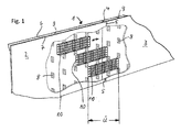
- Fig. 1 is a highly schematic part of a building 1 shown, which consists in the illustrated embodiment of two semi-finished components 2 and 3, which are joined together with a shock 4.
- a building according to the invention may also consist of more than two semi-finished components and in addition to the semi-finished components also have differently shaped components that may be finished parts, semi-finished parts or locally manufactured components.
- At the joint 4 creates a joint 5, which can remain unprocessed in the ideal case 1 in the ideal case.
- the two semi-finished components 2 and 3 are each formed of wall plates 6 and 7, which are spaced apart by means of stabilizing elements 8.
- the wall panels 6 and 7 extend in two mutually parallel planes and thus form a gap 9, which can be filled with hardenable casting compound, for example concrete.
- the stabilizing elements 8 are formed, for example, as a flat structure with a meandering or wavy cross section. As will be shown and described in the following embodiments, other stabilizing elements, such as rod-shaped stabilizing elements are advantageously used, but they must fulfill the purpose to fix the wall plates 6 and 7 stable in their parallel distance and spatially positioning of Modiretationalen reinforcement elements enable.
- multi-directional reinforcing elements is used in the present subject matter of the invention to make it clear that the reinforcing elements expand in several (at least two) directions. This term is intended to distinguish the objects so designated from the common term “multi-dimensional” because every object used in construction practice is, physically considered, “multi-dimensional”. A simple rod is inevitably “multidimensional,” because as a physical body it is “multidimensional,” but it extends in one direction only, so by definition it is “unidirectional.” By definition, the "multi-directional" reinforcing elements used according to the invention expand into a plurality of directions (directions).
- the space 9 are multi-directional reinforcing elements in the form of baskets 10 which are arranged as prefabricated assemblies in the space 9 longitudinally displaceable. They slide on the flat, wave-shaped stabilizing elements 8, by which they are largely fixed in their position within the interstices 9 to their horizontal displaceability.
- the baskets 10 are shifted in the longitudinal direction so far that they span the joint 5 in the area of the joint 4 and create a sufficient Studentsgreifungsdorf Ü required for the stability of the structure 1.
- the gap 9 can be poured with in-situ concrete. It is understood that instead of in-situ concrete any other hardening mass can be filled in the interspaces 9.
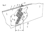
- Fig. 2 an embodiment of the invention is shown, which is a variant of the embodiment according to Fig. 1 represents.
- three-directional baskets 10 are slid obliquely into the interstices 9 of the wall panels 6 and 7 in the area of the impact.
- the stabilizing elements 8 are arranged so that open spaces for insertion of the three-directional baskets 10 result.
- the oblique insertion of the baskets 10 can be done manually or mechanically - ie actively - but it can also be used gravity, with their Help the baskets 10 slide into their final position.
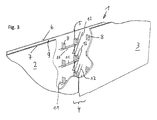
- Fig. 3 is shown a further variant of the invention.
- the assembled semi-finished components 2 and 3 substantially correspond to those already known to the Fig. 1 and 2 have been described.
- the stabilizing elements 8 are assigned permanently to multi-directional reinforcing elements in the form of bidirectional brackets 11, the brackets 11 spanning in two directions a plane perpendicular to the planes in which the wall panels 6 and 7 extend.
- the brackets 11 and 12 are referred to as two-directional reinforcing elements, whereas the baskets 10 described above extend in a further direction and are therefore referred to as three-directional reinforcing elements.
- the two-directional stirrups 11 cooperate with the stabilizing elements 8 and are preferably fastened to them.
- More bidirectional reinforcing elements in the form of positionable brackets 12 are introduced into the space 9 of the other semi-finished component 3 and there shifted in the direction of the first semi-finished component 2 and optionally tilted until the positionable bracket 12 with the rigid brackets 11 in the other half finished Component 2 cooperate and produce in this way the required overlap length Ü.
- Fig. 4 is the end position of the positioned in the manner described above bracket 12 within the gap 9 illustrated.
- the positionable bracket 12 and connected to the stabilizing elements 8 bracket 11 are with a predetermined overlap each other. In this position, they are fixed with split pins 13, which are arranged in the region of the joint 4 within the intermediate space 9 and cooperate for reinforcement with the brackets 11 and 12.
- Fig. 5 is another variant of the subject invention shown.
- rigidly mounted bracket 11 and positionable bracket 12 are shown.
- the peculiarity of the current embodiment is that the rigidly mounted bracket 11 were already cast in the manufacture of the semi-finished component 2 together with the stabilizing elements 8 in the wall panels 6 and 7. They are therefore "invisible" which is to be illustrated by the dashed representation in the left half of the figure.
- the bracket 11 are schematically visible.
- the positionable bracket 12 are introduced in the same manner in the gap 9 as to the embodiments of the Fig. 3 and 4 has already been explained.
- Cotter pins 13 also provide in this variant of the invention the reinforcement connection of both types of brackets, so that a sufficient reinforcement and overlapping length Ü is ensured in the region of the joint 4.
- Fig. 6 illustrates a detail of a building 1, in which a corner of the building 1 is shown.
- Two semi-finished components 2 and 3 have been assembled on the construction site to form a corner joint.
- the semi-finished components 2 and 3 are formed in a known manner by two wall plates 6 and 7 respectively.
- the mutually parallel wall plates 6 and 7 are connected to each other by stabilizing elements 8.
- the flat, wave-shaped stabilizing elements 8 can be formed by rod-shaped stabilizing elements 14.
- the overlapping length required for stability is generated by means of positionable brackets 12 in the intermediate space 9 of the semi-finished components 2 and 3.
- the positionable stirrups 12 are overlapped by being inserted and tilted in the area of impact 4 of the corner and can be fixed by means of splints 13, as shown in FIG Fig. 7 - which shows an advanced assembly phase - is shown.
- FIG. 8 and 9 Another embodiment of the invention is shown, in which a three-directional basket is used as a reinforcing element, which is made of horizontal brackets 16 and vertical bars 17.
- a three-directional basket is used as a reinforcing element, which is made of horizontal brackets 16 and vertical bars 17.
- stabilizing elements In the embodiments described, plate-like or wave-shaped shapes have always been represented and described as stabilizing elements.
- the stabilizing elements can also have other shapes, for example a rod shape, or can be used in different forms of stabilizing elements or arranged in groups.
Abstract
Die Erfindung bezieht sich auf ein Bauwerk (1), welches aus mehreren Halbfertig-Bauteilen (2, 3) zusammengefügt ist. Die erforderliche Standfestigkeit wird dadurch erzielt, dass an den mit Stoß (4) zusammengefügten Halbfertig-Bauteilen (2, 3) positionierbare Bewehrungselemente (10, 15) mit Stabilisierungselementen (8) zusammenwirken, die sich in einem Zwischenraum (9) zwischen den Wandplatten (6, 7) befinden. Die am Stoß (4) positionierbaren Bewehrungselemente (10) erstrecken sich über einen Bereich, der als Übergreifungslänge (Ü) bezeichnet wird.The invention relates to a building (1) which is assembled from a plurality of semi-finished components (2, 3). The requisite stability is achieved in that positionable reinforcing elements (10, 15) cooperate with stabilizing elements (8) on the semi-finished components (2, 3) assembled with joint (4), which are located in a space (9) between the wall plates (9). 6, 7) are located. The reinforcing elements (10) which can be positioned at the joint (4) extend over a region which is referred to as overlap length (Ü).
Description
Die vorliegende Erfindung bezieht sich auf ein Bauwerk bestehend aus mehreren mit Stoß zusammengefügten Halbfertig-Bauteilen gemäß dem Oberbegriff des Anspruchs 1.The present invention relates to a building consisting of several assembled with joint semi-finished components according to the preamble of
Es gibt verschiedene Ansätze, Bauwerke auch für den Erschütterungsfall standsicher zu gestalten. Man kann beispielsweise die Gebäudekonstruktion so steif anlegen, dass sie im Erschütterungsfall aller Voraussicht nach im linearen Verformungsbereich bleibt. Damit geht aber ein erheblicher, ökonomisch in der Regel nur schwer zu rechtfertigender Bauaufwand einher.There are various approaches to make buildings stable even for the vibration case. For example, it is possible to create a building structure that is so stiff that, in the event of vibration, it will in all probability remain in the linear deformation area. But this is accompanied by a significant, economically usually difficult to justify construction costs.
Alternativ besteht die Möglichkeit, Energiedissipationszonen in ein Bauwerk einzubauen. Diese sollen die während einer Erschütterung auf das Bauwerk einwirkende Energie durch bewusst in Kauf genommene Zerstörung aufnehmen. Dabei ist nachteilig, dass nicht selten irreparable Schäden an dem Bauwerk auftreten.Alternatively, it is possible to install energy dissipation zones in a building. These are intended to absorb the energy applied to the structure during a vibration by intentionally accepting destruction. It is disadvantageous that not infrequently irreparable damage to the structure occur.
In der Broschüre des Wirtschaftsministeriums Baden-Württemberg "
Aus der Praxis und aus der Literatur sind darüber hinaus weitere Veröffentlichungen bekannt. Als Beispiele sollen hier einige Patent-Veröffentlichungen zitiert werden.In addition, further publications are known from practice and from the literature. As examples, some patent publications are cited here.
Aus der
Ein völlig anderer Vorschlag ist aus der
Ein weiteres Beispiel zum erdbebensicheren Bauen wird in der
Aufgabe der vorliegenden Erfindung ist es, ein Bauwerk zu schaffen, welches mit ökonomisch vertretbarem Aufwand eine höhere Festigkeit aufweist, als mit den bekannten Maßnahmen des Stands der Technik.Object of the present invention is to provide a building, which has a higher strength with economically reasonable effort, as with the known measures of the prior art.
Diese Aufgabe wird durch ein Bauwerk mit den Merkmalen des Anspruchs 1 gelöst. Vorteilhafte Ausgestaltungen der Erfindung sind Gegenstand der abhängigen Ansprüche.This object is achieved by a building with the features of
Die besonderen Vorteile des erfindungsgemäßen Bauwerks liegen in dessen einfacher Herstellbarkeit, die keine übermäßigen Neuinvestitionen seitens des Her-stellungsbetriebs erfordern. Die Anforderungen an das Fachpersonal bleiben im bekannten Rahmen, der Energieaufwand zur Herstellung des Bauwerks wird nicht erhöht und kann gegebenenfalls sogar sinken. Nicht zuletzt wird die Standfestigkeit des Bauwerks deutlich erhöht.The particular advantages of the structure according to the invention lie in its ease of manufacture, which do not require excessive new investments on the part of the manufacturing operation. The demands on the specialist personnel remain in the known framework, the energy required to produce the building is not increased and may possibly even decrease. Last but not least, the stability of the structure is significantly increased.
Weiterhin ist ein Bauwerk vorteilhaft, wenn es aus mehreren mit Stoß zusammen gefügten Halbfertig-Bauteilen besteht, welche aus Wandplatten gebildet werden, die mit Hilfe von Verbindungs- bzw. Stabilisierungselementen beabstandet sind und im Wesentlichen in parallelen Ebenen zueinander verlaufen, deren so entstehenden Zwischenräume mit einer aushärtbaren Gießmasse befüllbar sind, und die jeweils am Stoß eine Fuge bilden, und bei dem die Verbindungs- bzw. Stabilisierungselemente von stabförmigen und/oder flächigen Abstandshaltern gebildet werden die im Wesentlichen rechtwinklig zu den Ebenen der Wandplatten verlaufen, und bei dem zumindest die Stabilisierungselemente im Bereich des Stoßes mit positionierbaren, mehrdirektionalen Bewehrungselementen zusammenwirken, wobei die mehrdirektionalen Bewehrungselemente in Ebenen verlaufen, die im Wesentlichen rechtwinklig zu den Ebenen der Wandplatten verlaufen.Furthermore, a building is advantageous if it consists of several joined together with shock semi-finished components consisting of wall panels are formed, which are spaced apart by means of connecting or stabilizing elements and extend substantially in parallel planes to each other, the interstices thus formed are filled with a curable casting composition, and each forming a joint at the junction, and in which the connection or Stabilizing elements are formed by rod-shaped and / or flat spacers which extend substantially perpendicular to the planes of the wall panels, and in which at least the stabilizing elements in the region of the joint interact with positionable, multi-directional reinforcing elements, wherein the multi-directional reinforcing elements run in planes which are substantially perpendicular to the planes of the wall panels.
Ferner ist ein Bauwerk vorteilhaft, bei dem die Stabilisierungselemente durch stabförmige und/oder flächige Verbundbauteile realisiert sind, die mit den positionierbaren mehrdirektionalen Bewehrungselementen zusammenwirken.Furthermore, a structure is advantageous in which the stabilizing elements are realized by rod-shaped and / or planar composite components, which interact with the positionable multi-directional reinforcement elements.
Darüber hinaus hat ein Bauwerk Vorteile, wenn die positionierbaren mehrdirektionalen Bewehrungselemente durch Körbe oder durch Bügel gebildet werden. Wobei es besonders günstig ist, wenn die positionierbaren mehrdirektionalen Bewehrungselemente verschiebbar und/oder kippbar angeordnet sind.In addition, a building has advantages when the positionable multi-directional reinforcing elements are formed by baskets or by brackets. Whereby it is particularly favorable if the positionable multi-directional reinforcement elements are arranged to be displaceable and / or tiltable.
Ein Bauwerk kann besonders vorteilhaft gestaltet sein, wenn die positionierbaren mehrdirektionalen Bewehrungselemente mit weiteren Bewehrungselementen zusammenwirken, wobei die weiteren Bewehrungselemente mit Stabilisierungselementen verbunden und/oder fest in den Wandplatten verankert sind.A building can be designed particularly advantageous if the positionable multidirectional reinforcing elements cooperate with other reinforcing elements, wherein the other reinforcing elements connected to stabilizing elements and / or are firmly anchored in the wall panels.
Ein Bauwerk gemäß der Erfindung ist außerordentlich standfest, wenn durch das Zusammenwirken der Stabilisierungselemente und/oder der weiteren Bewehrungselementen mit den positionierbaren mehrdirektionalen Bewehrungselementen über den Stoß hinweg eine statisch erforderliche Übergreifungslänge geschaffen wird.A building according to the invention is extremely stable when a statically required overlap length is created by the interaction of the stabilizing elements and / or the further reinforcing elements with the positionable multi-directional reinforcing elements over the impact.
Weitere Merkmale und Vorteile der Erfindung ergeben sich aus den folgenden bevorzugten Ausführungsbeispielen, die anhand der Zeichnungen näher erläutert werden.Further features and advantages of the invention will become apparent from the following preferred embodiments, which are explained in more detail with reference to the drawings.
Es zeigt:
- Fig. 1
- zwei mit Stoß zusammengefügte Halbfertig-Bauteile in schematisierter Darstellung,
- Fig. 2
- eine Variante der Halbfertig-Bauteile gemäß
Fig. 1 , - Fig. 3
- eine weitere Variante zweier mit Stoß zusammengefügter Halbfertig-Bauteile,
- Fig. 4
- die Variante gemäß
Fig. 3 in einer anderen Montagephase, - Fig. 5
- eine zusätzliche Variante zweier mit Stoß zusammengefügter Halbfertig-Bauteile,
- Fig. 6
- ein Detail zweier mit Stoß an einer Ecke zusammengefügter Halbfertig-Bauteile in schematisierter Darstellung,
- Fig. 7
- die Variante gemäß
Fig. 6 in einer anderen Montage-Phase, - Fig. 8
- eine weitere Ausführungsform der Erfindung vor dem Verschieben eines Bewehrungselementes und
- Fig. 9
- die Ausführungsform von
Fig. 8 nach dem Verschieben des Bewehrungselementes.
- Fig. 1
- two semi-finished components assembled with joints in schematic representation,
- Fig. 2
- a variant of the semi-finished components according to
Fig. 1 . - Fig. 3
- Another variant of two assembled with joint semi-finished components,
- Fig. 4
- the variant according to
Fig. 3 in another assembly phase, - Fig. 5
- an additional variant of two half-finished components assembled with joints,
- Fig. 6
- a detail of two semi-finished components joined together with a joint at a corner, in a schematic representation,
- Fig. 7
- the variant according to
Fig. 6 in another assembly phase, - Fig. 8
- a further embodiment of the invention prior to moving a reinforcing element and
- Fig. 9
- the embodiment of
Fig. 8 after moving the reinforcement element.
In
Die Stabilisierungselemente 8 sind z.B. als flächige Gebilde mit mäanderförmigem oder welligem Querschnitt ausgebildet. Wie in den nachfolgenden Ausführungsbeispielen gezeigt und beschrieben werden wird, sind auch andere Stabilisierungselemente, beispielsweise stabförmige Stabilisierungselemente mit Vorteil einsetzbar, sie müssen jedoch den Zweck erfüllen, die Wandplatten 6 und 7 stabil in ihrem parallelen Abstand zu fixieren und räumlich eine Positionierung von mehrdirektionalen Bewehrungselementen zu ermöglichen.The stabilizing
Der Begriff "mehrdirektionale" Bewehrungselemente wird definitionsgemäß beim vorliegenden Gegenstand der Erfindung gebraucht, um klar zu stellen, dass sich die Bewehrungselemente in mehrere (mindestens zwei) Richtungen ausdehnen. Dieser Begriff soll die so bezeichneten Gegenstände gegenüber dem gebräuchlichen Begriff "mehrdimensional" unterscheiden, weil jeder in der Baupraxis verwendete Gegenstand, physikalisch betrachtet, "mehrdimensional" ist. Ein einfacher Stab ist zwangsläufig "mehrdimensional", weil er als physikalischer Körper "mehrdimensional" ist, aber er erstreckt sich in nur eine Richtung, er ist also per Definition "eindirektional". Die erfindungsgemäß eingesetzten "mehrdirektionalen" Bewehrungselemente dehnen sich also definitionsgemäß in mehrere Direktionen (Richtungen) aus.By definition, the term "multi-directional" reinforcing elements is used in the present subject matter of the invention to make it clear that the reinforcing elements expand in several (at least two) directions. This term is intended to distinguish the objects so designated from the common term "multi-dimensional" because every object used in construction practice is, physically considered, "multi-dimensional". A simple rod is inevitably "multidimensional," because as a physical body it is "multidimensional," but it extends in one direction only, so by definition it is "unidirectional." By definition, the "multi-directional" reinforcing elements used according to the invention expand into a plurality of directions (directions).
In dem Zwischenraum 9 befinden sich mehrdirektionale Bewehrungselemente in Form von Körben 10 die als vorgefertigte Baugruppen in dem Zwischenraum 9 längsverschiebbar angeordnet sind. Dabei gleiten sie auf den flächigen, wellenförmigen Stabilisierungselementen 8, durch die sie in ihrer Lage innerhalb der Zwischenräume 9 bis auf ihre horizontale Verschiebbarkeit weitgehend festgelegt sind. Nach dem Aufstellen der Halbfertig-Bauteile 2 und 3 auf der Baustelle werden die Körbe 10 in Längsrichtung soweit verschoben, dass sie im Bereich des Stoßes 4 die Fuge 5 überspannen und eine zur Standfestigkeit des Bauwerks 1 erforderliche hinreichende Übergreifungslänge Ü schaffen. Wenn sich die Körbe 10 in ihrer bestimmungsgemäßen Lage bzw. Position befinden, kann der Zwischenraum 9 mit Ortbeton ausgegossen werden. Es versteht sich, dass an Stelle von Ortbeton auch jede andere aushärtende Masse in die Zwischenräume 9 eingefüllt werden kann.In the
In
In
In
In
In den
In den beschriebenen Ausführungsformen wurden als Stabilisierungselemente immer platten- bzw. wellenförmige Formen dargestellt und beschrieben. Die Stabilisierungselemente können aber auch andere Formen, z.B. eine Stangenform, aufweisen bzw. können unterschiedlichen Formen von Stabilisierungselementen gemischt oder gruppenweise angeordnet verwendet werden.In the embodiments described, plate-like or wave-shaped shapes have always been represented and described as stabilizing elements. However, the stabilizing elements can also have other shapes, for example a rod shape, or can be used in different forms of stabilizing elements or arranged in groups.
- 11
- Bauwerkbuilding
- 22
- Halbfertig-BauteilSemi-finished component
- 33
- Halbfertig-BauteilSemi-finished component
- 44
- Stoßshock
- 55
- FugeGap
- 66
- Wandplattewall plate
- 77
- Wandplattewall plate
- 88th
- flächige Stabilisierungselementeplanar stabilization elements
- 99
- Zwischenraumgap
- 1010
- Körbebaskets
- 1111
- Bügelhanger
- 1212
- positionierbare Bügelpositionable stirrups
- 1313
- Splintecotter pins
- 1414
- stabförmige Stabilisierungselementerod-shaped stabilizing elements
- 1515
- Korbbasket
- 1616
- horizontale Bügelhorizontal straps
- 1717
- vertikale Bügelvertical bars
- 1818
- Schwertsword
- 1919
- Pfeilarrow
- 2020
- Pfeilarrow
Claims (8)
Applications Claiming Priority (1)
| Application Number | Priority Date | Filing Date | Title |
|---|---|---|---|
| ATA308/2013A AT514300B1 (en) | 2013-04-15 | 2013-04-15 | building |
Publications (2)
| Publication Number | Publication Date |
|---|---|
| EP2792805A1 true EP2792805A1 (en) | 2014-10-22 |
| EP2792805B1 EP2792805B1 (en) | 2019-09-18 |
Family
ID=50549275
Family Applications (1)
| Application Number | Title | Priority Date | Filing Date |
|---|---|---|---|
| EP14450015.4A Active EP2792805B1 (en) | 2013-04-15 | 2014-04-14 | Wallelement consisting of prefabricated elements |
Country Status (2)
| Country | Link |
|---|---|
| EP (1) | EP2792805B1 (en) |
| AT (1) | AT514300B1 (en) |
Cited By (1)
| Publication number | Priority date | Publication date | Assignee | Title |
|---|---|---|---|---|
| GB2526533A (en) * | 2014-05-09 | 2015-12-02 | Charcon Ltd | Method and apparatus for rebar tying |
Families Citing this family (2)
| Publication number | Priority date | Publication date | Assignee | Title |
|---|---|---|---|---|
| US11248383B2 (en) | 2018-09-21 | 2022-02-15 | Cooper E. Stewart | Insulating concrete form apparatus |
| EP4253693A1 (en) | 2022-03-29 | 2023-10-04 | Georg Weidner | Spacer |
Citations (5)
| Publication number | Priority date | Publication date | Assignee | Title |
|---|---|---|---|---|
| EP1146179A2 (en) * | 2000-04-10 | 2001-10-17 | Angelo Candiracci | Pre-armed formwork building panel |
| US20050155306A1 (en) * | 2004-01-21 | 2005-07-21 | Jeffrey Childres | Joining clip for insulated concrete forms |
| DE102007014366A1 (en) * | 2007-03-26 | 2008-10-02 | Gerhard Maier | Reinforcement device for prefabricated parts |
| EP2410100A1 (en) * | 2010-07-19 | 2012-01-25 | Fehr | Integral formwork wall with connecting reinforcement |
| EP2495375A1 (en) * | 2011-03-02 | 2012-09-05 | H&H Technologies | Integral formwork wall with pivotable mobile connecting element |
Family Cites Families (4)
| Publication number | Priority date | Publication date | Assignee | Title |
|---|---|---|---|---|
| DE29902384U1 (en) * | 1999-02-11 | 2000-07-20 | Rojek Richard | Reinforcement device |
| FR2942824B1 (en) * | 2009-03-09 | 2016-07-01 | Fehr | INTEGRATED FORMWORK WALL WITH CONNECTION FRAME |
| CN201649354U (en) * | 2009-12-18 | 2010-11-24 | 安徽建筑工业学院 | Anti-seismic laminated plate type shear wall with I-shaped connecting component |
| FR2965829B1 (en) * | 2010-10-07 | 2012-10-12 | Fehr Groupe | WALL WITH LOST FORMWORK WITH CONNECTING CABLE. |
-
2013
- 2013-04-15 AT ATA308/2013A patent/AT514300B1/en not_active IP Right Cessation
-
2014
- 2014-04-14 EP EP14450015.4A patent/EP2792805B1/en active Active
Patent Citations (5)
| Publication number | Priority date | Publication date | Assignee | Title |
|---|---|---|---|---|
| EP1146179A2 (en) * | 2000-04-10 | 2001-10-17 | Angelo Candiracci | Pre-armed formwork building panel |
| US20050155306A1 (en) * | 2004-01-21 | 2005-07-21 | Jeffrey Childres | Joining clip for insulated concrete forms |
| DE102007014366A1 (en) * | 2007-03-26 | 2008-10-02 | Gerhard Maier | Reinforcement device for prefabricated parts |
| EP2410100A1 (en) * | 2010-07-19 | 2012-01-25 | Fehr | Integral formwork wall with connecting reinforcement |
| EP2495375A1 (en) * | 2011-03-02 | 2012-09-05 | H&H Technologies | Integral formwork wall with pivotable mobile connecting element |
Cited By (1)
| Publication number | Priority date | Publication date | Assignee | Title |
|---|---|---|---|---|
| GB2526533A (en) * | 2014-05-09 | 2015-12-02 | Charcon Ltd | Method and apparatus for rebar tying |
Also Published As
| Publication number | Publication date |
|---|---|
| AT514300B1 (en) | 2015-10-15 |
| AT514300A1 (en) | 2014-11-15 |
| EP2792805B1 (en) | 2019-09-18 |
Similar Documents
| Publication | Publication Date | Title |
|---|---|---|
| WO2007068267A1 (en) | Wooden building element for constructing the walls of a building | |
| DE60314459T2 (en) | CONSTRUCTION ELEMENT FOR CABINET CONSTRUCTION | |
| EP2792805B1 (en) | Wallelement consisting of prefabricated elements | |
| DE102012217689A1 (en) | Wall formwork and wall formwork system | |
| EP1783293B1 (en) | Reinforced insulating body for a prefabricated insulated wall element and wall element and method of manufacture | |
| EP2816168B1 (en) | Cladding stone for connection with a concrete ceiling | |
| EP3363968A1 (en) | Earthquake-proof connection of a bracing structure to a frame structure | |
| EP3299524B1 (en) | Wall made of prefabricated products and method for manufacturing the same | |
| EP2276898B1 (en) | Prefabricated component with stabilization device | |
| EP1959069B1 (en) | Reinforced fill-dam body for a unilaterally thermally insulated prefabricated wall section and prefabricated wall section and method for its production | |
| DE877488C (en) | Process for the production of double-shell walls from building boards and building board, in particular lightweight building board, for this purpose | |
| WO2004072398A1 (en) | Lost casing body | |
| DE2020381C3 (en) | Cooling tower with a spatial supporting structure comprising several floors | |
| EP2937481B1 (en) | Thermally insulating component | |
| DE102020117356B3 (en) | Set of elements for the production of a strip foundation with at least one foundation corner and method for the production of formwork for a strip foundation with at least one foundation corner | |
| EP1767715A2 (en) | A glass brick wall | |
| DE102017120254A1 (en) | Angle element and reveal panel with an angle element | |
| AT515973B1 (en) | Earthquake stirrups | |
| DE2351786A1 (en) | STRUCTURE AND METHOD FOR MANUFACTURING IT | |
| EP3153635B1 (en) | Thermally insulating component | |
| WO2020254255A1 (en) | Wall system | |
| EP2175079A2 (en) | Method for forming a rigid corner reinforcement for reinforced concrete construction, reinforcement element and rigid corner reinforcement | |
| DE2142188A1 (en) | Process for the production of shell structures and wall components for such structures | |
| DE1129674B (en) | Reinforced concrete cooling tower, the shell of which consists essentially of prefabricated parts | |
| DE102016120047A1 (en) | Device and method for the integral production of a three side elements and a floor element and / or a ceiling element having room module |
Legal Events
| Date | Code | Title | Description |
|---|---|---|---|
| PUAI | Public reference made under article 153(3) epc to a published international application that has entered the european phase |
Free format text: ORIGINAL CODE: 0009012 |
|
| 17P | Request for examination filed |
Effective date: 20140414 |
|
| AK | Designated contracting states |
Kind code of ref document: A1 Designated state(s): AL AT BE BG CH CY CZ DE DK EE ES FI FR GB GR HR HU IE IS IT LI LT LU LV MC MK MT NL NO PL PT RO RS SE SI SK SM TR |
|
| AX | Request for extension of the european patent |
Extension state: BA ME |
|
| R17P | Request for examination filed (corrected) |
Effective date: 20150422 |
|
| RBV | Designated contracting states (corrected) |
Designated state(s): AL AT BE BG CH CY CZ DE DK EE ES FI FR GB GR HR HU IE IS IT LI LT LU LV MC MK MT NL NO PL PT RO RS SE SI SK SM TR |
|
| STAA | Information on the status of an ep patent application or granted ep patent |
Free format text: STATUS: EXAMINATION IS IN PROGRESS |
|
| 17Q | First examination report despatched |
Effective date: 20180313 |
|
| REG | Reference to a national code |
Ref country code: DE Ref legal event code: R079 Ref document number: 502014012666 Country of ref document: DE Free format text: PREVIOUS MAIN CLASS: E04B0002860000 Ipc: E04C0005160000 |
|
| GRAP | Despatch of communication of intention to grant a patent |
Free format text: ORIGINAL CODE: EPIDOSNIGR1 |
|
| STAA | Information on the status of an ep patent application or granted ep patent |
Free format text: STATUS: GRANT OF PATENT IS INTENDED |
|
| RIC1 | Information provided on ipc code assigned before grant |
Ipc: E04C 5/16 20060101AFI20190328BHEP Ipc: E04B 2/86 20060101ALI20190328BHEP |
|
| INTG | Intention to grant announced |
Effective date: 20190415 |
|
| GRAS | Grant fee paid |
Free format text: ORIGINAL CODE: EPIDOSNIGR3 |
|
| GRAA | (expected) grant |
Free format text: ORIGINAL CODE: 0009210 |
|
| STAA | Information on the status of an ep patent application or granted ep patent |
Free format text: STATUS: THE PATENT HAS BEEN GRANTED |
|
| AK | Designated contracting states |
Kind code of ref document: B1 Designated state(s): AL AT BE BG CH CY CZ DE DK EE ES FI FR GB GR HR HU IE IS IT LI LT LU LV MC MK MT NL NO PL PT RO RS SE SI SK SM TR |
|
| REG | Reference to a national code |
Ref country code: GB Ref legal event code: FG4D Free format text: NOT ENGLISH |
|
| REG | Reference to a national code |
Ref country code: CH Ref legal event code: EP |
|
| REG | Reference to a national code |
Ref country code: DE Ref legal event code: R096 Ref document number: 502014012666 Country of ref document: DE |
|
| REG | Reference to a national code |
Ref country code: CH Ref legal event code: NV Representative=s name: BOVARD AG PATENT- UND MARKENANWAELTE, CH Ref country code: AT Ref legal event code: REF Ref document number: 1181470 Country of ref document: AT Kind code of ref document: T Effective date: 20191015 |
|
| REG | Reference to a national code |
Ref country code: IE Ref legal event code: FG4D Free format text: LANGUAGE OF EP DOCUMENT: GERMAN |
|
| REG | Reference to a national code |
Ref country code: NL Ref legal event code: MP Effective date: 20190918 |
|
| PG25 | Lapsed in a contracting state [announced via postgrant information from national office to epo] |
Ref country code: FI Free format text: LAPSE BECAUSE OF FAILURE TO SUBMIT A TRANSLATION OF THE DESCRIPTION OR TO PAY THE FEE WITHIN THE PRESCRIBED TIME-LIMIT Effective date: 20190918 Ref country code: LT Free format text: LAPSE BECAUSE OF FAILURE TO SUBMIT A TRANSLATION OF THE DESCRIPTION OR TO PAY THE FEE WITHIN THE PRESCRIBED TIME-LIMIT Effective date: 20190918 Ref country code: BG Free format text: LAPSE BECAUSE OF FAILURE TO SUBMIT A TRANSLATION OF THE DESCRIPTION OR TO PAY THE FEE WITHIN THE PRESCRIBED TIME-LIMIT Effective date: 20191218 Ref country code: NO Free format text: LAPSE BECAUSE OF FAILURE TO SUBMIT A TRANSLATION OF THE DESCRIPTION OR TO PAY THE FEE WITHIN THE PRESCRIBED TIME-LIMIT Effective date: 20191218 Ref country code: SE Free format text: LAPSE BECAUSE OF FAILURE TO SUBMIT A TRANSLATION OF THE DESCRIPTION OR TO PAY THE FEE WITHIN THE PRESCRIBED TIME-LIMIT Effective date: 20190918 Ref country code: HR Free format text: LAPSE BECAUSE OF FAILURE TO SUBMIT A TRANSLATION OF THE DESCRIPTION OR TO PAY THE FEE WITHIN THE PRESCRIBED TIME-LIMIT Effective date: 20190918 |
|
| REG | Reference to a national code |
Ref country code: LT Ref legal event code: MG4D |
|
| PG25 | Lapsed in a contracting state [announced via postgrant information from national office to epo] |
Ref country code: GR Free format text: LAPSE BECAUSE OF FAILURE TO SUBMIT A TRANSLATION OF THE DESCRIPTION OR TO PAY THE FEE WITHIN THE PRESCRIBED TIME-LIMIT Effective date: 20191219 Ref country code: LV Free format text: LAPSE BECAUSE OF FAILURE TO SUBMIT A TRANSLATION OF THE DESCRIPTION OR TO PAY THE FEE WITHIN THE PRESCRIBED TIME-LIMIT Effective date: 20190918 Ref country code: RS Free format text: LAPSE BECAUSE OF FAILURE TO SUBMIT A TRANSLATION OF THE DESCRIPTION OR TO PAY THE FEE WITHIN THE PRESCRIBED TIME-LIMIT Effective date: 20190918 Ref country code: AL Free format text: LAPSE BECAUSE OF FAILURE TO SUBMIT A TRANSLATION OF THE DESCRIPTION OR TO PAY THE FEE WITHIN THE PRESCRIBED TIME-LIMIT Effective date: 20190918 |
|
| PG25 | Lapsed in a contracting state [announced via postgrant information from national office to epo] |
Ref country code: NL Free format text: LAPSE BECAUSE OF FAILURE TO SUBMIT A TRANSLATION OF THE DESCRIPTION OR TO PAY THE FEE WITHIN THE PRESCRIBED TIME-LIMIT Effective date: 20190918 Ref country code: PT Free format text: LAPSE BECAUSE OF FAILURE TO SUBMIT A TRANSLATION OF THE DESCRIPTION OR TO PAY THE FEE WITHIN THE PRESCRIBED TIME-LIMIT Effective date: 20200120 Ref country code: EE Free format text: LAPSE BECAUSE OF FAILURE TO SUBMIT A TRANSLATION OF THE DESCRIPTION OR TO PAY THE FEE WITHIN THE PRESCRIBED TIME-LIMIT Effective date: 20190918 Ref country code: PL Free format text: LAPSE BECAUSE OF FAILURE TO SUBMIT A TRANSLATION OF THE DESCRIPTION OR TO PAY THE FEE WITHIN THE PRESCRIBED TIME-LIMIT Effective date: 20190918 Ref country code: ES Free format text: LAPSE BECAUSE OF FAILURE TO SUBMIT A TRANSLATION OF THE DESCRIPTION OR TO PAY THE FEE WITHIN THE PRESCRIBED TIME-LIMIT Effective date: 20190918 Ref country code: RO Free format text: LAPSE BECAUSE OF FAILURE TO SUBMIT A TRANSLATION OF THE DESCRIPTION OR TO PAY THE FEE WITHIN THE PRESCRIBED TIME-LIMIT Effective date: 20190918 |
|
| PG25 | Lapsed in a contracting state [announced via postgrant information from national office to epo] |
Ref country code: SM Free format text: LAPSE BECAUSE OF FAILURE TO SUBMIT A TRANSLATION OF THE DESCRIPTION OR TO PAY THE FEE WITHIN THE PRESCRIBED TIME-LIMIT Effective date: 20190918 Ref country code: CZ Free format text: LAPSE BECAUSE OF FAILURE TO SUBMIT A TRANSLATION OF THE DESCRIPTION OR TO PAY THE FEE WITHIN THE PRESCRIBED TIME-LIMIT Effective date: 20190918 Ref country code: SK Free format text: LAPSE BECAUSE OF FAILURE TO SUBMIT A TRANSLATION OF THE DESCRIPTION OR TO PAY THE FEE WITHIN THE PRESCRIBED TIME-LIMIT Effective date: 20190918 Ref country code: IS Free format text: LAPSE BECAUSE OF FAILURE TO SUBMIT A TRANSLATION OF THE DESCRIPTION OR TO PAY THE FEE WITHIN THE PRESCRIBED TIME-LIMIT Effective date: 20200224 |
|
| REG | Reference to a national code |
Ref country code: DE Ref legal event code: R097 Ref document number: 502014012666 Country of ref document: DE |
|
| PLBE | No opposition filed within time limit |
Free format text: ORIGINAL CODE: 0009261 |
|
| STAA | Information on the status of an ep patent application or granted ep patent |
Free format text: STATUS: NO OPPOSITION FILED WITHIN TIME LIMIT |
|
| PG2D | Information on lapse in contracting state deleted |
Ref country code: IS |
|
| PG25 | Lapsed in a contracting state [announced via postgrant information from national office to epo] |
Ref country code: DK Free format text: LAPSE BECAUSE OF FAILURE TO SUBMIT A TRANSLATION OF THE DESCRIPTION OR TO PAY THE FEE WITHIN THE PRESCRIBED TIME-LIMIT Effective date: 20190918 Ref country code: IS Free format text: LAPSE BECAUSE OF FAILURE TO SUBMIT A TRANSLATION OF THE DESCRIPTION OR TO PAY THE FEE WITHIN THE PRESCRIBED TIME-LIMIT Effective date: 20200119 |
|
| 26N | No opposition filed |
Effective date: 20200619 |
|
| PG25 | Lapsed in a contracting state [announced via postgrant information from national office to epo] |
Ref country code: SI Free format text: LAPSE BECAUSE OF FAILURE TO SUBMIT A TRANSLATION OF THE DESCRIPTION OR TO PAY THE FEE WITHIN THE PRESCRIBED TIME-LIMIT Effective date: 20190918 |
|
| REG | Reference to a national code |
Ref country code: DE Ref legal event code: R119 Ref document number: 502014012666 Country of ref document: DE |
|
| PG25 | Lapsed in a contracting state [announced via postgrant information from national office to epo] |
Ref country code: MC Free format text: LAPSE BECAUSE OF FAILURE TO SUBMIT A TRANSLATION OF THE DESCRIPTION OR TO PAY THE FEE WITHIN THE PRESCRIBED TIME-LIMIT Effective date: 20190918 |
|
| REG | Reference to a national code |
Ref country code: CH Ref legal event code: PL |
|
| PG25 | Lapsed in a contracting state [announced via postgrant information from national office to epo] |
Ref country code: LU Free format text: LAPSE BECAUSE OF NON-PAYMENT OF DUE FEES Effective date: 20200414 Ref country code: CH Free format text: LAPSE BECAUSE OF NON-PAYMENT OF DUE FEES Effective date: 20200430 Ref country code: LI Free format text: LAPSE BECAUSE OF NON-PAYMENT OF DUE FEES Effective date: 20200430 Ref country code: DE Free format text: LAPSE BECAUSE OF NON-PAYMENT OF DUE FEES Effective date: 20201103 |
|
| REG | Reference to a national code |
Ref country code: BE Ref legal event code: MM Effective date: 20200430 |
|
| PG25 | Lapsed in a contracting state [announced via postgrant information from national office to epo] |
Ref country code: BE Free format text: LAPSE BECAUSE OF NON-PAYMENT OF DUE FEES Effective date: 20200430 |
|
| GBPC | Gb: european patent ceased through non-payment of renewal fee |
Effective date: 20200414 |
|
| PG25 | Lapsed in a contracting state [announced via postgrant information from national office to epo] |
Ref country code: IE Free format text: LAPSE BECAUSE OF NON-PAYMENT OF DUE FEES Effective date: 20200414 Ref country code: GB Free format text: LAPSE BECAUSE OF NON-PAYMENT OF DUE FEES Effective date: 20200414 |
|
| REG | Reference to a national code |
Ref country code: AT Ref legal event code: MM01 Ref document number: 1181470 Country of ref document: AT Kind code of ref document: T Effective date: 20200414 |
|
| PG25 | Lapsed in a contracting state [announced via postgrant information from national office to epo] |
Ref country code: AT Free format text: LAPSE BECAUSE OF NON-PAYMENT OF DUE FEES Effective date: 20200414 |
|
| PG25 | Lapsed in a contracting state [announced via postgrant information from national office to epo] |
Ref country code: IT Free format text: LAPSE BECAUSE OF NON-PAYMENT OF DUE FEES Effective date: 20200414 |
|
| PG25 | Lapsed in a contracting state [announced via postgrant information from national office to epo] |
Ref country code: MT Free format text: LAPSE BECAUSE OF FAILURE TO SUBMIT A TRANSLATION OF THE DESCRIPTION OR TO PAY THE FEE WITHIN THE PRESCRIBED TIME-LIMIT Effective date: 20190918 Ref country code: CY Free format text: LAPSE BECAUSE OF FAILURE TO SUBMIT A TRANSLATION OF THE DESCRIPTION OR TO PAY THE FEE WITHIN THE PRESCRIBED TIME-LIMIT Effective date: 20190918 |
|
| PG25 | Lapsed in a contracting state [announced via postgrant information from national office to epo] |
Ref country code: MK Free format text: LAPSE BECAUSE OF FAILURE TO SUBMIT A TRANSLATION OF THE DESCRIPTION OR TO PAY THE FEE WITHIN THE PRESCRIBED TIME-LIMIT Effective date: 20190918 |
|
| P01 | Opt-out of the competence of the unified patent court (upc) registered |
Effective date: 20230517 |
|
| PGFP | Annual fee paid to national office [announced via postgrant information from national office to epo] |
Ref country code: FR Payment date: 20230424 Year of fee payment: 10 |
|
| PGFP | Annual fee paid to national office [announced via postgrant information from national office to epo] |
Ref country code: TR Payment date: 20230413 Year of fee payment: 10 |