EP2495375A1 - Integral formwork wall with pivotable mobile connecting element - Google Patents
Integral formwork wall with pivotable mobile connecting element Download PDFInfo
- Publication number
- EP2495375A1 EP2495375A1 EP12305249A EP12305249A EP2495375A1 EP 2495375 A1 EP2495375 A1 EP 2495375A1 EP 12305249 A EP12305249 A EP 12305249A EP 12305249 A EP12305249 A EP 12305249A EP 2495375 A1 EP2495375 A1 EP 2495375A1
- Authority
- EP
- European Patent Office
- Prior art keywords
- wall
- movable element
- skins
- movable
- rotation
- Prior art date
- Legal status (The legal status is an assumption and is not a legal conclusion. Google has not performed a legal analysis and makes no representation as to the accuracy of the status listed.)
- Granted
Links
- 238000009415 formwork Methods 0.000 title claims description 58
- 238000009416 shuttering Methods 0.000 claims description 21
- 230000000295 complement effect Effects 0.000 claims description 6
- 239000007769 metal material Substances 0.000 claims description 3
- 230000000694 effects Effects 0.000 description 17
- 230000005484 gravity Effects 0.000 description 7
- 238000006073 displacement reaction Methods 0.000 description 5
- 238000004519 manufacturing process Methods 0.000 description 5
- 229910000831 Steel Inorganic materials 0.000 description 4
- 239000010959 steel Substances 0.000 description 4
- 238000010276 construction Methods 0.000 description 3
- 239000000463 material Substances 0.000 description 3
- 238000009958 sewing Methods 0.000 description 3
- 239000004744 fabric Substances 0.000 description 2
- 238000005304 joining Methods 0.000 description 2
- 239000002184 metal Substances 0.000 description 2
- 239000004033 plastic Substances 0.000 description 2
- 239000002023 wood Substances 0.000 description 2
- 238000004026 adhesive bonding Methods 0.000 description 1
- 239000004794 expanded polystyrene Substances 0.000 description 1
- 238000009434 installation Methods 0.000 description 1
- 210000000056 organ Anatomy 0.000 description 1
- 238000011084 recovery Methods 0.000 description 1
- 230000002787 reinforcement Effects 0.000 description 1
- 238000004513 sizing Methods 0.000 description 1
- 238000003466 welding Methods 0.000 description 1
Images


Classifications
-
- E—FIXED CONSTRUCTIONS
- E04—BUILDING
- E04B—GENERAL BUILDING CONSTRUCTIONS; WALLS, e.g. PARTITIONS; ROOFS; FLOORS; CEILINGS; INSULATION OR OTHER PROTECTION OF BUILDINGS
- E04B2/00—Walls, e.g. partitions, for buildings; Wall construction with regard to insulation; Connections specially adapted to walls
- E04B2/84—Walls made by casting, pouring, or tamping in situ
- E04B2/86—Walls made by casting, pouring, or tamping in situ made in permanent forms
- E04B2/8611—Walls made by casting, pouring, or tamping in situ made in permanent forms with spacers being embedded in at least one form leaf
- E04B2/8617—Walls made by casting, pouring, or tamping in situ made in permanent forms with spacers being embedded in at least one form leaf with spacers being embedded in both form leaves
-
- E—FIXED CONSTRUCTIONS
- E04—BUILDING
- E04B—GENERAL BUILDING CONSTRUCTIONS; WALLS, e.g. PARTITIONS; ROOFS; FLOORS; CEILINGS; INSULATION OR OTHER PROTECTION OF BUILDINGS
- E04B2/00—Walls, e.g. partitions, for buildings; Wall construction with regard to insulation; Connections specially adapted to walls
- E04B2/84—Walls made by casting, pouring, or tamping in situ
- E04B2/86—Walls made by casting, pouring, or tamping in situ made in permanent forms
- E04B2/8635—Walls made by casting, pouring, or tamping in situ made in permanent forms with ties attached to the inner faces of the forms
-
- E—FIXED CONSTRUCTIONS
- E04—BUILDING
- E04C—STRUCTURAL ELEMENTS; BUILDING MATERIALS
- E04C5/00—Reinforcing elements, e.g. for concrete; Auxiliary elements therefor
- E04C5/16—Auxiliary parts for reinforcements, e.g. connectors, spacers, stirrups
- E04C5/162—Connectors or means for connecting parts for reinforcements
- E04C5/166—Connectors or means for connecting parts for reinforcements the reinforcements running in different directions
- E04C5/167—Connection by means of clips or other resilient elements
-
- E—FIXED CONSTRUCTIONS
- E04—BUILDING
- E04B—GENERAL BUILDING CONSTRUCTIONS; WALLS, e.g. PARTITIONS; ROOFS; FLOORS; CEILINGS; INSULATION OR OTHER PROTECTION OF BUILDINGS
- E04B2/00—Walls, e.g. partitions, for buildings; Wall construction with regard to insulation; Connections specially adapted to walls
- E04B2/84—Walls made by casting, pouring, or tamping in situ
- E04B2/86—Walls made by casting, pouring, or tamping in situ made in permanent forms
- E04B2002/8676—Wall end details
Definitions
- the present invention relates to a wall formwork integrated with at least one movable element to connect the wall to another wall juxtaposed.
- the invention also relates to a kit for producing such an integrated formwork wall and comprising a plurality of these movable elements.
- the invention relates to the field of the building and, more particularly, that of the factory manufacture of walls intended to be conveyed to a site where they are located as part of the construction of a building.
- such a movable element is engaged in the internal volume of two walls juxtaposed, this at the junction between these two walls and the top of these walls.
- a first disadvantage of such a type of wall consists in that it comprises means for connecting together the two skins of such a wall and in that the presence of these connection means hampers the progression of a movable element. during his engagement in the internal volume of these walls.
- Another disadvantage is that this type of wall is only suitable for the construction of buildings outside seismic zones in which it is necessary to sew two walls juxtaposed, this by performing an overlap between the frames of these two walls juxtaposed.
- a solution to this problem has been provided by a second type of wall incorporating a movable armature designed to adopt a retracted position inside the wall as well as an extended position in which this mobile armature extends outside this wall. , laterally with respect to this wall, and in the extension of the internal volume of this wall. In the case of two walls juxtaposed, the mobile armature that includes such a wall can then extend inside the internal volume of the other wall juxtaposed, this to seam these two walls juxtaposed.
- This type of wall requires, however, to ensure the displacement by shifting of such a movable armature, this from a retracted position to an extended position.
- such a wall is provided with openings allowing the introduction, inside this wall, of a tool designed to ensure such a displacement.
- This type of wall has, however, many disadvantages.
- it is necessary to resort to a specific tool, to provide openings in the walls requiring subsequent intervention to ensure closure, besides such a displacement can be hampered by the presence of means to connect the two skins of each of these walls.
- Such a joining device takes the form of a clip and comprises, on the one hand, a first end provided with a first attachment means and, on the other hand, a second end, opposite to the first end, and provided with a second attachment means.
- the establishment of such a clip consists, in a first step, to achieve the attachment of the first hooking means of this clip on a connecting means that includes a first form and, in a second step, to clip the second hooking means of this clip on a means for connecting that has a second shape, this to ensure the junction between these two forms and the clamping of these two forms together.
- Such a device has many disadvantages.
- this device requires an adjusted sizing of the clip as well as precise positioning, on the one hand, of the two forms relative to one another and, on the other hand, means for connecting, each with respect to the form that he equips.
- a staple can be put in place on two shapes only after positioning so juxtaposed or superimposed of these two forms.
- this installation must be performed manually and by exerting a considerable effort to perform the clipping of the second attachment means, this to ensure the tightening of both forms.
- the establishment of such a staple can be made only near the (lateral, respectively upper or lower) end of an edge (upper, respectively lateral) of a shape, this in immediate border of such a form.
- junction between two forms is, therefore, made only punctually and only near the end of such an edge of such a shape which generates a junction fault between the two forms elsewhere than near the end of such an edge, especially over the rest of the length of the edge of such a shape.
- a staple is simply hooked on a means for connecting so that a simple handling error can lead to a stall of this staple which then falls into the bottom of the internal volume of a form causing its loss without possibility of recovery .
- the present invention aims to overcome the disadvantages of integrated formwork walls of the state of the art.
- This wall formwork integrated is characterized in that it comprises at least one member designed to mount such a rotating member on a means for connecting the two skins of the wall, this between a retracted position and an extended position of this element mobile.
- the invention also relates to a kit for producing an integrated formwork wall having the characteristics mentioned above and comprising a plurality of movable elements.
- the present invention relates to an integrated formwork wall having at least one member movable in rotation between a retracted position and an extended position.
- the wall comprises at least one means for driving at least one movable element in rotation, from a retracted position and to an extended position of this movable element.
- a drive means is constituted, as the case may be, by a means (consisting of the weight of at least a part of this movable element and / or by a position of the member for rotating this movable element on the means for connecting two skins of the wall) to recall this movable element or by at least one pulling accessible from outside the wall.
- This avoids, advantageously, to use a specific tool and / or to provide openings in the wall.
- This also makes it possible to deploy a mobile element in the deployed position inside the internal volume of at least one wall, in particular in places inaccessible to the human hand or for a tool.
- a movable element that comprises a wall makes it easy to position such a device.
- mobile element near a connection means (more particularly in support against such a connecting means) that comprises another wall juxtaposed, which allows for an effective seam between these two walls juxtaposed.
- such a movable element is rotatably mounted on a means for connecting two skins of a wall, by means of said member for mounting such a member movable in rotation on such connecting means.
- This feature advantageously makes it possible to equip with at least one such movable element an integrated formwork wall, either during its manufacturing process (in particular by directly using connection means of two skins equipped with at least one mobile element), either after manufacture of this wall (more particularly after hardening of the concrete constituting the two skins of this wall and by joining at least one movable element of a connection means), or again after having conveyed such a wall on a construction site.
- This feature then makes it possible, advantageously, to equip, with at least one movable element, an existing integrated formwork wall, in particular of traditional design.
- This allows, in particular, to equip, with at least one movable element, an integrated formwork wall initially intended for use in non-seismic zone to make it advantageously usable for use in seismic zone.
- a particular embodiment consists in that the member designed for rotational mounting takes the form of a complementary piece consisting of a ligature or a ball joint equipping the movable member.
- the movable element which comprises the member designed for rotational mounting (this member can, then, be incorporated in the movable element or equip it ) which advantageously makes it possible to avoid using a complementary part to ensure such rotational mounting.
- the integrated form wall includes means for holding the mounted movable member rotation on a means for connecting two skins.
- the movable element which comprises or which receives such a means for maintaining, or the member for the rotational assembly which constitutes such a means for maintaining.
- This holding means advantageously makes this movable element integral with this means for connecting two skins, this in spite of the rotational movements of this movable element and / or the movements of the wall.
- the integrated form wall may comprise a plurality of movable elements distributed over the entire height of such a wall. This allows, advantageously, to make a connection and a seam between two walls, this on the entire height of these two walls.
- the present invention relates to the field of the building and, more particularly, that of the manufacture of walls with integrated formwork.
- such integrated wall form 1 comprises two skins (2; 3), arranged facing one (2; 3) of the other (3; 2), substantially parallel, and spaced so to define between them an internal volume 4 on the wall 1.
- Such skin (2; 3) can be made of wood or the like.
- Such a skin (2; 3) may, again, be made of a hydraulic material, more particularly of concrete or the like.
- such a skin (2; 3) can incorporate at least one structural reinforcement (more particularly in the form of a lattice resulting from an assembly of a plurality of bars, in particular metal).
- Such integrated formwork wall 1 comprises, again, means 5 for connecting these two skins (2; 3) between them.
- Such means 5 for connecting these two skins (2; 3) between them comprises at least one cross member (50; 50 '), on the one hand, extending along an axis perpendicular to the planes of these two skins (2; ) and, on the other hand, having two ends, one of which is associated with a skin 2 of the wall 1 while the other is associated with the other skin 3 of this wall 1.
- such an end may, then and as the case may be, be embedded in the skin (2; 3) of such a wall 1 when the latter (2; 3) is made of a hydraulic material or be made integral (directly or indirectly) with such a skin (2; 3), especially by screwing gluing or other, when the skin (2; 3) is made of wood or the like.
- such means 5 for connecting these two skins (2; 3) may be constituted by a connector at least partly constituted by a cross member (50; 50 ') as mentioned above.
- Such a means 5 for connecting these two skins (2; 3) may also be constituted by a staple adopting a "U" shape and having, on the one hand, two parallel branches, one of which is associated (embedded or secured as aforesaid) to a skin 2 of the wall 1 while the other is associated with the other skin 3 of the wall 1 and, secondly, a cross, connecting these two parallel branches, and having the characteristics mentioned therein. -above.
- Such a means 5 for connecting these two skins (2; 3) can be constituted by a binding armor adopting the shape of a basket or a basket ( figures 5 , 12 to 14 ).
- a connecting armature comprises, on the one hand, a plurality of bars parallel to each other, arranged in the form of a parallelogram (in particular rectangle or square), and some of which are associated (embedded or secured as mentioned above) to a skin 2 of the wall 1 while the others are associated with the other skin 3 of the wall 1.
- Such a connecting armature further comprises means for connecting these bars together.
- These connection means take the form of a plurality of frames or the like, made by folding a bar, extending in a plane perpendicular to the parallel bars and made integral with these parallel bars.
- Such a frame incorporates at least one cross member having the characteristics mentioned above and for connecting two skins (2; 3).
- the integral form wall 1 comprises at least one element 6 designed to connect the wall 1 to another wall 1 'similar and juxtaposed.
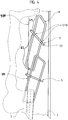
- This element 6 is movable between, on the one hand, a retracted position ( figures 4 , 5 , and 13 ) in which this movable element 6 is at least partially (or entirely as illustrated) figure 4 ) retracted inside the internal volume 4 of the wall 1 and, on the other hand, an extended position ( Figures 1 to 3 , 12 and 14 ) in which a part of this movable element 6 extends laterally and externally with respect to this wall 1, in the extension of the internal volume 4 of the wall 1, this in order to extend inside the internal volume d 'another wall 1' similar and juxtaposed.
- such a movable element 6 comprises a first part 60 extending inside the internal volume 4 of this wall 1, this as well in the retracted position as in the deployed position of this mobile element 6.
- This first part 60 then comprises a free end 61 extending, then, also inside this internal volume 4.
- This movable element 6 also comprises a second part 62 which, on the one hand and in the deployed position of the movable element 6, extends laterally with respect to this wall 1, outside this wall 1, in the extension of the internal volume 4 of the wall 1, and is intended to extend inside the internal volume of another wall 1 'similar and juxtaposed. On the other hand and in the retracted position of the movable element 6, this second part 62 extends at least in part (or even entirely as figure 4 ) inside the internal volume 4 of this wall 1.
- This second portion 62 has a free end 63 extending outside the internal volume 4 of the wall 1, this at least in the deployed position of the movable member 6.
- the wall 1 is designed so that, in the rest position of the movable element 6, this movable element 6 adopts an extended position in which the second portion 62 of this movable element 6 extends completely outside the internal volume 4 from this wall 1.
- Such a type of embodiment advantageously allows the second part 62 of such a movable element 6 to be positioned appropriately and automatically in the internal volume of another similar wall 1 'and juxtaposed with the integrated formwork wall 1 comprising this movable element 6, this during the positioning of the wall 1 comprising this movable element 6 (first illustrated embodiment figures 2 and 11 to 18 ), respectively of this other wall 1 '(second illustrated embodiment figure 3 ), juxtaposed with this other wall 1 ', respectively to the wall 1 having such a movable member 6 as will be described below.
- the wall 1 is designed so that, in the rest position of the movable element 6, this movable element 6 adopts a retracted position in which the second portion 62 of this movable element 6 extends integrally inside the internal volume 4 of this wall 1.
- Such an embodiment advantageously makes it possible to prevent such a mobile element 6 from extending outside the wall 1, in particular during the manufacturing and handling steps of such a wall 1.
- the integrated form wall 1 comprises at least one movable element 6 between a retracted position and an extended position.
- the integrated formwork wall 1 also comprises at least one member 7 designed to mount such a movable element 6 in rotation on a means 5 for connecting two skins (2; 3) of the wall 1, this between a such a retracted position and such an extended position of this movable element 6.
- the integrated form wall 1 may comprise, as the case may be, a single member 7 or a plurality of these members 7 (in particular 2 as visible Figures 2 to 5 , 9 to 18 ) to ensure the mounting of such a movable element 6 in rotation on such a connecting means 5.
- the integrated form wall 1 comprises at least one movable element 6.
- a wall 1 comprises, in fact, a plurality of these movable elements 6
- an integrated form wall 1 usually comprises a plurality of means 5 for connecting the two skins (2; 3) between them.
- this wall 1 also comprises a plurality of members 7 to make such a movable element 6 integral in rotation with such means 5 to connect two skins (2; 3).
- such means 5 for connecting two skins (2; 3) comprises at least one cross member (50; 50 ') extending along an axis perpendicular to the plane of these two skins (2; 3).
- said member 7 for mounting a mobile element 6 in rotation on a means 5 for connecting two skins (2; 3) is, then, designed to allow rotation of this movable element 6 around the extension axis d such a cross member (50; 50 ') or about an axis parallel to this axis of extension, more particularly in a direction perpendicular to this axis.
- such a mounting member 7 is, in fact, designed to allow free rotation of the movable member 6 relative to the means 5 to connect two skins (2; 3), more particularly by relative to a crossbar (50; 50 ') that comprises this means 5.
- FIG. 1 to 10 a first family of walls 1 with integrated formwork.
- the integrated formwork walls 1 conforming to this first family comprise at least one movable element 6 and at least one element 7 designed to mount such a movable element 6 in rotation on a means 5 for connecting the two skins (2; such a wall 1.
- said member 7 is constituted by a complementary piece (70; equipping said movable element 6 and / or said means 5 to connect the two skins (2; 3).
- said member 7 for mounting a mobile element 6 in rotation on a means 5 for connecting two skins (2; 3) is constituted by a ligation 70, in particular implemented using a ligating gun and / or performed using a wire, more particularly a wire, for example a wire.
- such a member 7 for mounting a mobile element 6 in rotation on a means 5 for connecting two skins (2; 3) is constituted by a ball 71.
- Such a ball 71 comprises, on the one hand, a means 710 for receiving a means 5 for connecting two skins (2; 3), more particularly for receiving a crosspiece 50 that comprises such means 5 and which extends in a direction perpendicular to the planes of the skins (2; 3).
- this receiving means 710 is, more particularly, designed to allow rotation of the ball 71 with respect to this means 5 for connecting two skins (2; 3).
- this ball 71 comprises means 711 for receiving a mobile element 6 extending in a determined direction, in particular perpendicular to the direction of extension of the means 5 for connecting two skins (2; 3), more particularly a crosspiece 50 that includes such means 5.
- this receiving means 711 is more particularly designed to ensure immobilization of this movable element 6 with respect to said ball joint 71.
- such a ball 71 takes the form of a jumper, in particular of the clipping type or the like, comprising, on the one hand, a bottom in which is positioned a means 5 for connecting two skins (2; 3) and constituting the means 710 for receiving such means 5 for connecting two skins (2; 3).
- the bottom of this jumper is designed to allow a rotation of this jumper relative to the means 5 to connect two skins (2; 3).
- this jumper comprises two branches, connected together by the bottom, and provided with a means 711 for receiving a movable element 6.
- this means 711 for receiving a movable member 6 is designed to ensure immobilization of such a movable member 6 with respect to this jumper.
- this means 711 for receiving a movable member 6 is constituted by a notch whose shape and / or dimensions allow a tight engagement (and, therefore, immobilization) of a movable member 6 inside that cut.
- such a ball 71 takes the form of a plate having, on the one hand, a through opening through which is engaged a means 5 for connecting two skins (2; 3) and constituting the means 710 for the reception of such means 5 for connecting two skins (2; 3).
- this through opening is designed to allow a rotation of this plate relative to the means 5 for connecting two skins (2; 3).
- this plate comprises a receptacle, fitted laterally on one side of the plate, and constituting the means 711 for receiving a mobile element 6.
- this means 711 for receiving a movable member 6 is designed to ensure immobilization of such a movable member 6 relative to said plate.
- this plate preferably adopts the shape of a disk.
- said through opening is centrally formed with respect to the plate while the receptacle is laterally offset from the central opening.
- the receptacle is constituted by a sleeve, or even (and preferably) by clipping means, more particularly defined by a sleeve having a slot longitudinal through which said movable member 6 is engaged within the receptacle.
- said through opening may be completed by a notch extending, more particularly diverging, from the through opening and towards the lateral edge of the plate.
- This notch makes it possible, advantageously, to place the ball 71 on the means 5 to connect two skins (2; 3), this by engaging this connecting means 5 inside the cut-through to the opening .
- said ball 71 comprises a means for retaining the means 5 for connecting two skins (2; 3) within the through opening.
- Such means for retaining may be constituted by clipping means or the like, for example defined by a section of the through opening greater than the width of the notch at the outlet of this through opening.
- the ball joints 71 described above are more particularly suitable for mounting on a means 5 for connecting two skins (2; 3) of a portion of a movable element 6 extending in one direction. perpendicular to the extension direction of this means 5 for connecting two skins (2; 3).
- the means 710 for receiving a means 5 for connecting two skins (2; 3) and the means 711 for receiving a movable member 6 extend substantially in a perpendicular direction.
- some embodiments consist in ensuring the mounting on a means 5 for connecting two skins (2; 3) of a portion of a movable member 6 (more particularly a crosspiece that comprises such a movable element 6 under form) extending in a direction parallel to such means 5.
- the means 710 for receiving a means 5 for connecting two skins (2; 3) and the means 711 for the receiving a movable element 6 that includes such a ball 71 extend substantially according to a parallel direction.
- the means 710 for receiving a means 5 for connecting two skins (2; 3) and / or the means 711 for receiving a movable member 6 allow rotation of the swivel 71 relative to this means. 5 for connecting two skins (2; 3) and / or with respect to this movable element 6.
- the wall 1 with integral formwork comprises at least one means 8 for holding such a movable member 6 on a means 5 for connecting two skins (2; 3).
- the presence of such a means 8 to maintain advantageously makes it possible to secure and retain such a movable element 6 and such a means 5 to connect, in spite of the rotation of this movable element 6 with respect to this means 5 for connecting and the handling of the wall 1.
- the means 8 for maintaining can then be constituted by the member 7 itself, more particularly by the ligature 70 or by the ball 71, in particular by means (710; 711) that has such a ball 71.
- said movable member 6 is preferably made of a metallic material, more particularly steel.
- This movable element 6 takes the form of a rod, a bar, a "U" -shaped piece, a frame (in particular rectangular as visible on the Figures 2 to 5 , 9 and 10 appended and corresponding to the preferred embodiment of the invention) or the like.
- the integrated form wall 1 also comprises at least one means 9 for driving at least one mobile element 6 in rotation, from a retracted position and towards an extended position of this movable element 6.
- such means 9 for rotating in a deployed position at least one movable member 6 is constituted by means for biasing such a movable member 6 towards its deployed position, when such a movable member 6 has previously been brought out of its deployed position and towards a position (at least partly) retracted.
- such a means for recalling this movable element 6 is constituted by the weight of at least a part of this movable element 6 and / or by a position of the member 7 to rotate this movable element 6 on a means 5 to connect two skins (2; 3) of the wall 1, with respect to this movable element 6.
- the mobile element 6 comprises at least a first portion 64 including the second portion 62 (outer) of this movable member 6 and at least a portion of the first portion 60 of this movable element 6.
- This first portion 64 extends between the member 7 and the free end 63 of the second portion 62 of the movable member 6 extending outside the wall 1 in the deployed position of this movable element 6.
- a first variant (not shown) consists in that this movable element 6 further comprises a second portion 65 extending between the member 7 and a free end 61 of the first portion 60 of the movable member 6 extending to the 1 inside the wall and opposite the free end 63 of the second part 62 mentioned above.
- the means for returning the movable element 6 is constituted by a weight of the first portion 64 of the movable element 6 which is greater than the weight of the second portion of this movable element 6.
- a second variant ( figure 2 ) is that this movable element 6 is devoid of such a second portion 65.
- the movable element 6 is then rotatably mounted on the means 5 to connect two skins (2; 3) by a member 7, this at the end of this movable member 6, more particularly at the end 61 of the first portion 60 (inner) of the movable member 6 extending inside the wall 1 and opposite the free end 63 of the second part 62 (external) mentioned above.
- the means for returning the movable element 6 is constituted by the weight of the first portion 64 of the movable element 6.
- the movable element 6 is constituted by a frame comprising a cross member, on the one hand, extending between the two skins (2; 3) of the wall 1 and in a direction parallel to the direction of extension of a crosspiece 50 that comprises a means 5 for connecting these two skins (2; 3) and, secondly, rotatably mounted on such a cross member 50, this through an organ 7 in the form of a ligature 70 or a ball 71.
- the movable element 6 (more particularly the second part 62 of this element mobile 6) can cooperate with a means 5 'for connecting the two skins of the other wall 1'.
- the movable member 6 Under the effect of this cooperation and a downward movement of the wall 1, the movable member 6 is moved out of its deployed position and to a position (at least partly) retracted.
- this cooperation is interrupted and the movable element 6 returns to its deployed position, this under the effect of the means for returning the movable element 6 to its deployed position (which is a position suitable for sewing between the two walls 1; 1 ') and automatically (under the effect of gravity).
- the wall 1 with integrated formwork may also comprise at least one removable means for keeping at least one movable member 6 in the retracted position, this at least during the positioning of a wall 1 integrated formwork juxtaposed to another wall 1 'integrated formwork.
- This means for keeping the movable element 6 in the retracted position prevents this movable element 6 from reaching its deployed position.
- Such a means for keeping the movable element 6 in the retracted position can take the form of a vertical bar designed adapted to cooperate with said movable member 6, more particularly with a free end (61; 63) thereof 6, in particular by taking support and / or was fixed reversibly there.
- this means to keep is removed from the wall 1 having the effect of allowing the movable member 6 to reach its deployed position, this under the effect of the means for reminding this movable member 6 to its deployed position (under the effect of gravity) and automatically.
- the wall 1 with integrated formwork may also include at least one means for driving at least one movable element 6 in rotation, this from an extended position and to a retracted position of this movable element 6.
- a means for driving acts against a means for driving at least one movable member 6 in rotation, this from a retracted position and to an extended position of this movable member 6.
- This means for driving to a retracted position can be constituted by at least one tie rod or the like integral with at least one such movable element 6 and accessible, or even manipulable, from the outside of the wall 1.
- the mobile element 6 comprises a first portion 64 comprising at least the second portion 62 of this movable member 6, or even (and preferably) a portion of the first portion 60 of this movable element 6.
- This movable element 6 comprises, again, a second portion 65 that includes the first portion 60 of this movable element 6 which, as mentioned above, extends inside the internal volume 4 of the integral form wall 1, this both in the retracted position in the deployed position of this movable element 6.
- this first portion 64 and this second portion 65 extending, for one 64, on one side and, for the other 65, on the other side, the member 7 designed to mount the movable member 6 in rotation on a means 5 for connecting two skins (2; 3) of the wall 1.
- this first portion 64 extends between the member 7 and the free end 63 of the second portion 62 of the movable member 6 while the second portion 65 extends between this member 7 and the free end 61 of the first portion 60 of the movable member 6.
- the means for returning the movable element 6 is constituted by the weight of the second portion 65 of the movable element 6 which is greater than the weight of the first portion 62 of this movable element 6.
- the movable element 6 when positioning in a manner juxtaposed with the integrated form wall 1 comprising such a movable element 6 of another integrated form wall 1 'similar, the movable element 6 (more particularly the second part 62 of this movable element 6) can cooperate with means for connecting the two skins of the other wall 1 '. Under the effect of this cooperation and a downward movement of the other wall 1 ', the movable member 6 is moved out of its deployed position and to a position (at least partly) retracted.
- this other wall 1 ' By continuing the downward movement of this other wall 1 ', this cooperation is interrupted and the movable element 6 returns to its deployed position, this under the effect of the means for reminding this movable element 6 to its deployed position (which is a suitable position for sewing between the two walls 1; 1 ') and automatically (under the effect of gravity).
- the wall 1 integrated formwork may, further comprise at least one removable means for keeping at least one movable member 6 in the retracted position, this at least during the positioning of a wall 1 integrated formwork juxtaposed to another wall 1 'integrated formwork.
- Such removable means has the same characteristics, the same functionality, and achieves the same result as mentioned above.
- the wall 1 with integrated formwork can also include at least one means (of the aforementioned type) for driving at least one movable element 6 in rotation, this from an extended position and to a retracted position of this movable element 6.
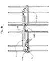
- the integrated shuttering wall 1 further comprises means 10 for limiting the rotation of the driven movable element 6 (more particularly recalled) towards its deployed position by the means 9 to drive (more particularly to recall) such a movable element 6.
- This means 10 for limiting the rotation completes the means for driving (recalling) the movable element 6 in the deployed position and is designed to retain the movable element 6 in its deployed position, this after such rotation from a retracted position of the movable element 6.
- Such a means 10 for limiting the rotation may be constituted by a means 5 for connecting two skins (2; 3) to one another, more particularly a crossmember 51 other than that 50 on which is rotatably mounted said movable member 6, in particular a cross member. 51 that also comprises the connecting armature (basket, basket as mentioned above) comprising the cross member 50 on which is provided such a mounting.
- Such a means 10 for limiting the rotation of the movable member 6 is designed so that in the deployed position, the movable member 6 extends substantially horizontally.
- the integral shuttering wall 1 comprises at least one means 9 for driving at least one movable element 6 in rotation, from a retracted position and towards an extended position of this movable element 6.
- such means 9 for driving towards an extended position at least one such movable element 6 is constituted by at least one tie rod 90 secured to at least one such movable element 6, extending inside the internal volume 4 of the wall 1, and accessible, even manipulable, from outside the wall 1.
- Such tie 90 can be flexible (especially in the form of a string, a rope, a cable or other) or rigid (especially in the form of a rod or the like). Such a pull 90 can then be made of steel, fabric, plastic or other.
- a movable element 6 comprising a first portion 64 incorporating at least the second portion 62 (outer) of this movable member 6, or even (and preferably) a part of the first part 60 of this movable element 6.
- This movable element 6 has, again, a second portion 65 that includes the first portion 60 (internal) of this movable member 6 which, as mentioned above, extending to inside the internal volume 4 of the integral form wall 1, this both in the retracted position and in the deployed position of this movable element 6.
- this first portion 64 and this second portion 65 extend, for one 64, on one side and for the other 65, on the other side, the member 7 designed to mount this movable member 6 in rotation on a means 5 for connecting two skins (2; 3) of the wall 1.
- this first portion 64 extends between the member 7 and the free end 63 of the second portion 62 of the movable member 6 while the second portion 65 extends between this member 7 and the free end 61 of the first portion 60 of the movable member 6.
- the means 9 for rotating in a deployed position at least one movable element 6 is then secured to this second portion 65 of such a movable element 6.
- the wall 1 further comprises means for driving at least one movable element 6 towards its retracted position, starting from an extended position of this movable element 6.
- such a means for driving at least one movable member 6 to its retracted position is constituted by a means for biasing this movable member 6 to its retracted position.
- This means for returning is constituted by the weight of at least a part of this movable element 6 and / or by a position of the member 7 for rotating this movable element 6 on the means 5 to connect two skins (2; 3) of the wall 1, with respect to this movable element 6.
- the means for returning such a movable element 6 is constituted by the weight of the second portion 65 of this movable element 6 which is greater than the weight of the first portion 64 of this mobile element 6
- this means for biasing such a movable member 6 has the effect of driving the movable member 6 in its retracted position under the effect of gravity.
- the means 9 for rotating at least one movable member 6 to an extended position acts against the means for driving such a movable member 6 to its retracted position which, because of the gravity, tends to reduce such a movable element 6 in its retracted position.
- This means 9 for rotating at least one movable member 6 to an extended position is then actuated after positioning of an integrated form wall 1 comprising such a movable member 6, this juxtaposed with another wall 1 'to integrated formwork similar.
- the integrated form wall 1 according to the invention may comprise a plurality of movable elements 6.
- said integral form wall 1 according to this second embodiment may be completed by at least one means 11 for interconnecting a plurality of movable elements 6.
- such a means 11 for connecting a plurality of movable elements 6 to each other may constitute a means 9 for driving (towards their deployed position or towards their retracted position) simultaneously in rotation a plurality of moving elements. 6 or, again, be completed by a means 9 (as mentioned above) for driving in rotation at least one such movable element 6.
- the invention also relates to a kit 12 for producing an integrated formwork wall 1 having the characteristics described above.
- kit 12 comprises a plurality of movable elements 6 with the characteristics mentioned above.
- kit 12 may also include a plurality of members 7, each equipping a movable member 6, and adapted to mount such a movable member 6 in rotation on a means 5 for connecting two skins (2; an integrated shuttering wall 1, this between a retracted position and an extended position of this movable element 6.
- this kit 12 may also include at least one means 9 for rotating at least one movable element 6 that includes this kit 12 (and preferably and the simultaneous rotation of a plurality of movable elements 6 of this kit 12) and / or at least one means 11 for interconnecting at least part (or all) of the movable elements 6 that includes this kit 12.
- kit 12 can then advantageously be sold independently of a formwork wall of conventional design and set up on such a wall, especially on site.
- a kit 12 can be put in place on walls that are suitable only for an application outside seismic zones which then become advantageously exploitable in seismic zones.
- the invention may also relate to a connecting armature comprising, on the one hand, a basket or basket of traditional design and described above and, on the other hand, a plurality of movable elements 6 as well as a plurality of members 7 designed to mount such a movable element 6 in rotation on such a connecting armature, or even at least one means 9 for driving in rotation at least one movable element 6 and / or at least one means 11 for interconnecting at least a portion of the movable elements 6.
- FIG. 11 to 18 a second family of walls 1 with integrated formwork.
- the integrated formwork walls 1 conforming to this second family include, again, the at least one movable element 6 and at least one element 7 designed to mount such a movable element 6 in rotation on a means 5 for connecting the two skins (2; 3) of such a wall 1.
- a movable member 6 which comprises at least one member 7 designed to mount the movable member 6 in rotation on a means 5 for connecting these two skins (2; 3).
- such a member 7 can then be incorporated in the movable element 6 or equip this mobile element 6 which advantageously makes it possible to avoid using a complementary part (as described above) that it should be implemented independently on the wall 1, this to ensure such rotational mounting.
- the member 7 for mounting the movable member 6 in rotation on a means 5 for connecting two skins (2; 3) and that comprises this movable member 6, is constituted by a housing 72 within which comes position such means 5 to connect two skins (2; 3), more particularly a crosspiece 50 that includes such means 5 to connect.
- this member 7 for mounting the mobile element 6 in rotation on a means 5 for connecting two skins (2; 3) and that comprises this movable element 6, is constituted by a hooking means 73, in the form of an attachment loop, a hook hook (preferred embodiment visible on the Figures 11 to 14 ) or the like.
- such a hooking means 73 then defines a housing 72 for receiving such means 5 for connecting two skin (2; 3).
- the member 7 for mounting the mobile element 6 in rotation on a means 5 for connecting two skins (2; 3) and that comprises this movable element 6, is constituted by a deformation of this movable element 6.
- this member 7 may be constituted by a deformation of a free end that comprises this movable element 6, in particular of the free end 61 of the first part 60 of the movable element 6 which extends inside the internal volume 4 of the wall 1 ( Figures 11 to 14 ).
- the latter comprises at least one long piece 66 comprising at least a part of the first part 60 and at least a part of the second part 62 of the movable element 6.
- a long piece 66 has the shape of a rod, a bar, a "U" -shaped piece ( Figures 11 to 16 and 18 ), a frame (including rectangular, figure 17 ) or the like.
- this longiform piece 66 which can then comprise said member 7 which can then be constituted by a deformation (as mentioned above) of this longiform piece 66, more particularly by a deformation of a free end of this longiform piece 66.
- such a movable element 6 may, again, comprise at least one additional piece 13, made integral with a long piece 66, and having at least the member 7 for mounting the movable member 6 in rotation on a means 5 for connect two skins (2; 3).
- Such an additional piece 13 can be made integral with the long-form piece 66 by welding ( Figures 15 and 16 ), by overmolding ( figure 17 ) or other according to the nature of the materials of these parts (longiform 66 and / or additional 13).
- this additional piece 13 which comprises, then, at least one such member 7 for mounting the movable member 6 in rotation on a means 5 for connecting two skins (2 3).
- such a member 7 may be constituted by a housing 72 (as mentioned above) and / or an attachment means 73 (as mentioned above) and / or deformation (as mentioned above). above) and that includes, then, this additional piece 13.
- Such additional piece 13 (or even the member 7 that includes such an additional piece 13) can then adopt the shape of a hook (particularly welded to the long-form piece 66 as visible figure 15 ), a clip (especially welded on the long-form piece 66 as visible figure 16 ), a jumper (in particular welded on the elongate piece 66), a housing (in particular overmolded on the long-form piece 66 as visible figure 17 ) Or other.
- the wall 1 with integral formwork comprises at least one means 8 for holding a movable member 6 on a means 5 for connecting the two skins (2; 3).
- the movable element 6 which comprises or receives such a means 8 to maintain this mobile element 6.
- such a means 8 to maintain is, more particularly, designed to maintain a member 7 (which comprises the movable member 6) rotatably mounted on a means 5 for connecting two skins (2; 3).
- the presence of such a means 8 to maintain advantageously makes it possible to secure and retain such a movable element 6 and such a means 5 to connect, despite the rotation of this mobile element 6 by relative to this means 5 for connecting.
- the movable element 6 comprises such a means 8 for holding the member 7 in rotation ( Figures 11 to 18 ).
- the means 8 for holding the member 7 of the movable member 6 rotatably mounted on the means 5 for connecting two skins (2; 3) is constituted by an opening that has the housing 72 of this member 7 and whose dimension is less than that of the means 5 for connecting two skins (2; 3) positioned inside this housing 72.
- Such an embodiment advantageously prevents this means 5 for connecting to disengage from its housing 72.
- the dimension of the opening that this housing 72 presents and / or the flexibility of the movable element 6 can advantageously be defined so as to allow the force introduction of the means 5 for connecting two skins (2; 3) inside this housing 72.
- the means 8 for holding the member 7 of the movable member 6 rotatably mounted on the means 5 to connect two skins (2; 3) is constituted by a stop, extending to the interior of the housing 72 and / or through the opening of this housing 72, and against which bears the means 5 for connecting two skins (2; 3).
- the movable element 6 comprises a long piece 66. Also and according to a first case, it is, more particularly, such a longiform piece 66 of this movable element 6 which can then comprise on the one hand, at least one member 7 for mounting the movable member 6 in rotation on a means 5 for connecting two skins (2; 3) and, on the other hand, at least one means 8 for holding the member 7 in rotation ( Figures 11 to 14 ).
- this mobile element 6 can, again, comprise an additional part 13.
- this additional part 13 comprises, on the one hand, at least one member 7 for mounting the mobile element 6 in rotation on a means 5 for connecting two skins (2; 3) and, on the other hand, at least one means 8 for holding the member 7 in rotation ( Figures 15 to 17 ).
- such a means 8 for maintaining the member 7 may, again, be constituted by a deformation of the movable member 6, more particularly of said piece (as the case may be, additional 13 or longiform 66 as visible Figures 11 to 14 ) that comprises this movable element 6.
- a particular embodiment consists in that the member 7 for mounting the mobile element 6 in rotation on a means 5 for connecting two skins (2; 3) and the means 8 to maintain such a member 7 in rotation are constituted by a deformation ( Figures 11 to 15 ).
- such an additional piece 13 may be constituted by a hook, a clip, a jumper, a case or the like.
- the elongated piece 66 of the mobile element 6 comprises at least one member 7 for mounting the mobile element 6 in rotation on a means 5 for connecting two skins (2 3) and, on the other hand, the additional piece 13 of this movable element 6 comprises at least one means 8 for holding the member 7 in rotation.
- the additional piece 13 of this movable element 6 comprises at least one means 8 for holding the member 7 in rotation.
- Such may be the case for an additional piece 13, overmoulded or engaged (in particular by interlocking) on the longiform piece 66, and comprising a stop, in particular in the form of a redan ( figure 18 ), and constituting the means 8 for holding the member 7 in rotation.
- the additional piece 13 of the mobile element 6 may comprise at least one member 7 for mounting the mobile element 6 in rotation on a means 5 for connecting two skins (2; 3) and / or at least one means 8 for maintain such a member 7 rotatably mounted on the means 5 for connecting two skins (2; 3).
- the movable element 6 receives such a means 8 to keep the member 7 in rotation.
- Such a means 8 for holding the member 7 in rotation can then take the form of a stop (having the characteristics mentioned above) and that comprises a support associated with the movable member 6.
- a support can adopt the form of a plate or the like, provided with such a stop, and having an opening inside which is engaged a portion of the movable member 6, more particularly the free end 61 of this movable member 6
- the movable member 6 further comprises at least one means for driving this mobile element 6 in rotation, this from a retracted position and to an extended position of this movable element 6.
- a preferred embodiment consists in that the means for driving the mobile element 6 in rotation is constituted by a means for biasing the movable member 6 towards its deployed position, when this movable element 6 has previously been brought out of its deployed position and towards a retracted position.
- the means for biasing the movable member 6 is constituted by the weight of at least a portion of this movable member 6 and / or by a position of the member 7 for mounting in position. rotating this movable element 6 on the means 5 to connect two skins (2; 3) of the wall 1, this with respect to this movable element 6.
- the movable member 6 is made of a metallic material, more particularly steel.
- this mobile element 6 (more particularly a long piece 66 that includes this movable element 6) takes the form of a rod, a bar, a frame (including rectangular, figure 17 ), a "U" shaped piece ( Figures 11 to 16 and 18 ) or the like.
- such a movable member 6 is in the form of a "U" -shaped piece with two branches and a connecting crossbar of these two branches.
- These two branches each have a free end each comprising a member 7 for mounting this mobile element 6 in rotation on a means 5 for connecting two skins (2; 3) of a wall 1, or even a means 8 for maintain this movable element 6 on such a means for connecting 5.
- Such a movable element 6 results from the deformation (in particular by folding) of a bar, in particular a metal rod.
- the invention thus relates to a movable element 6 having the characteristics described above.
- the invention also relates to an integrated formwork wall 1, corresponding to this second family of walls 1 with integrated formwork, and which, as described above, comprises two skins (2; 3) and means 5 for connect these two skins (2; 3) together.
- This integrated form wall 1 also comprises at least one element 6, movable between a retracted position and an extended position, designed to connect the wall 1 to another wall 1 'similar and juxtaposed.
- This movable element 6 comprises a first portion 60 (internal) and a second portion 62 (external) having the characteristics described above.
- This movable element 6 also has the characteristics described above and corresponding to this second family of walls 1 integrated formwork.
- the integrated shuttering wall 1 according to the invention and in accordance with this second family of walls 1 comprises, then, at least one member 7 designed to mount such a movable element 6 in rotation on a means 5 for connecting the two skins (2; 3) of the wall 1, this between a retracted position and an extended position of this movable element 6.
- the invention relates, more particularly, to such an integrated formwork wall 1 comprising at least one movable element 6, having the characteristics described above, and comprising at least one member 7 designed to mount this mobile element 6. in rotation on a means 5 for connecting the two skins (2; 3) of this integrated shuttering wall 1.
- this mobile element 6 comprises, in particular, at least one means for driving (return means) such a movable element 6 in rotation, this from a retracted position and towards an extended position of this movable element 6.
- the movable element 6 allows, advantageously and during the positioning an integrated form wall 1 comprising such a movable element 6 juxtaposed with another similar wall 1 ', this movable element 6 (more particularly the second portion 62 of the movable element 6) to cooperate with a means 5 'to connect the two skins of this other wall 1'. Under the effect of this cooperation and a downward movement of the wall 1, the movable member 6 is moved out of its deployed position and to a position (at least partly) retracted.
- the wall 1 with integrated formwork can, again, comprise at least one removable means for keeping at least one movable element 6 in the retracted position, this at least during the positioning of a wall 1 with integrated formwork. way juxtaposed to another wall 1 'integrated formwork.
- This means for keeping the movable element 6 in the retracted position prevents this movable element 6 from reaching its deployed position.
- such a means for keeping the movable member 6 in the retracted position can take the form of a vertical bar designed adapted to cooperate with said movable member 6, more particularly with a free end 63 thereof 6, in particular by taking support and / or was fixed reversibly there.
- this means to keep is removed from the wall 1 having the effect of allowing the movable member 6 to reach its deployed position, this under the effect of the means for reminding this movable member 6 to its deployed position (under the effect of gravity) and automatically.
- the wall 1 with integrated formwork may also include at least one means for driving at least one movable element 6 in rotation, this from an extended position and to a retracted position of this movable element 6.
- a means for driving acts against a means for driving (recalling) at least one movable member 6 in rotation, this from a retracted position and to an extended position of this movable member 6.
- This means for driving towards a retracted position may be constituted by at least one tie rod or the like, secured to at least one such movable member 6, accessible (or manipulable) from outside the wall 1, in particular extending inside the internal volume 4 of the wall 1
- Such a tie may be flexible (especially in the form of a string, a rope, a cable or other) or rigid (especially in the form of a rod or the like). Such a tie may, then, be made of steel, fabric, plastic or other.
- the integral form wall 1 conforming to this second family of walls 1 comprises, again, at least one means 10 for limiting the rotation of such a moving element 6 driven to its deployed position by the means for driving (recalling) this movable element 6.
- This means 10 for limiting rotation completes the means for driving the movable element 6 in the deployed position and is designed to retain this movable element 6 in its deployed position, after such rotation from a retracted position of the movable element 6.
- Such a means 10 for limiting the rotation may be constituted by a means 5 for connecting two skins (2; 3) to one another, more particularly by a crossmember 51 other than that 50 on which is rotatably mounted said movable member 6, in particular a crossbar 51 that also comprises the connecting armature (basket, basket as mentioned above) comprising the cross member 50 which is provided such a rotational mounting.
- Such a means 10 for limiting the rotation of the movable member 6 is designed so that in the deployed position, the movable member 6 extends substantially horizontally.
- the integrated form wall 1 may comprise a plurality of movable elements 6, a plurality of means 5 for connecting the two skins (2; 3) of the wall 1 between them and a plurality of members 7 for mounting such movable elements 6 in rotation on such means 5 for connecting the two skins (2; 3) of the wall 1.
- a wall 1 may then comprise least means for interconnecting a plurality of these movable elements 6.
- such a means for connecting a plurality of movable elements 6 to each other can then constitute a means for simultaneously driving in rotation a plurality of movable elements 6 from a deployed position to a retracted position. or, still, be completed by such means (as mentioned above) for rotating at least one such movable member 6.
- such a means for connecting the movable elements 6 may be constituted by a tie as described above.
- the invention may also relate to an armature (more particularly in the form of a basket, a basket or the like and as described above) and comprising at least one means 5 (as described above). ) for connecting two skins (2; 3) of an integrated form wall 1 (as described above), at least one movable member 6 (as described above) and at least one member 7 ( as described above) for mounting such a movable member 6 in rotation on such means 5 for connecting the two skins (2; 3) of the wall 1.
- an armature more particularly in the form of a basket, a basket or the like and as described above
- at least one means 5 for connecting two skins (2; 3) of an integrated form wall 1 (as described above)
- at least one movable member 6 as described above
- at least one member 7 as described above
Abstract
Description
La présente invention a trait à un mur à coffrage intégré comportant au moins un élément mobile pour relier ce mur à un autre mur juxtaposé. L'invention a, encore, trait à un kit pour la réalisation d'un tel mur à coffrage intégré et comportant une pluralité de ces éléments mobiles.The present invention relates to a wall formwork integrated with at least one movable element to connect the wall to another wall juxtaposed. The invention also relates to a kit for producing such an integrated formwork wall and comprising a plurality of these movable elements.
L'invention concerne le domaine du bâtiment et, plus particulièrement, celui de la fabrication en usine de murs destinés à être acheminés sur un chantier où ils sont implantés dans le cadre de la construction d'un bâtiment.The invention relates to the field of the building and, more particularly, that of the factory manufacture of walls intended to be conveyed to a site where they are located as part of the construction of a building.
On connaît, d'ores et déjà, de tels murs à coffrage intégré comportant ou recevant des éléments mobiles conçus pour assurer la liaison entre deux murs juxtaposés.Already known, such integrated formwork walls comprising or receiving movable elements designed to ensure the connection between two walls juxtaposed.
En fait et selon un premier type de mur, un tel élément mobile est engagé dans le volume interne de deux murs juxtaposés, ceci au niveau de la jonction entre ces deux murs et par le haut de ces murs. Un premier inconvénient d'un tel type de mur consiste en ce qu'il comporte des moyens pour raccorder entre elles les deux peaux d'un tel mur et en ce que la présence de ces moyens de raccordement entrave la progression d'un élément mobile lors de son engagement dans le volume interne de ces murs. Un autre inconvénient consiste en ce que ce type de mur convient uniquement pour la construction de bâtiments en dehors de zones sismiques dans lesquelles il est nécessaire de couturer deux murs juxtaposés, ceci en réalisant un chevauchement entre les armatures de ces deux murs juxtaposés.In fact and according to a first type of wall, such a movable element is engaged in the internal volume of two walls juxtaposed, this at the junction between these two walls and the top of these walls. A first disadvantage of such a type of wall consists in that it comprises means for connecting together the two skins of such a wall and in that the presence of these connection means hampers the progression of a movable element. during his engagement in the internal volume of these walls. Another disadvantage is that this type of wall is only suitable for the construction of buildings outside seismic zones in which it is necessary to sew two walls juxtaposed, this by performing an overlap between the frames of these two walls juxtaposed.
Une solution à ce problème a été apportée par un deuxième type de mur incorporant une armature mobile conçue pour adopter une position escamotée à l'intérieur de ce mur ainsi qu'une position déployée dans laquelle cette armature mobile s'étend en dehors de ce mur, latéralement par rapport à ce mur, et dans le prolongement du volume interne de ce mur. Dans le cas de deux murs juxtaposés, l'armature mobile que comporte un tel mur peut alors s'étendre à l'intérieur du volume interne de l'autre mur juxtaposé, ceci pour couturer ces deux murs juxtaposés. Ce type de mur impose, cependant, de pouvoir assurer le déplacement par ripage d'une telle armature mobile, ceci d'une position escamotée à une position déployée. Pour ce faire, un tel mur est pourvu d'ouvertures autorisant l'introduction, à l'intérieur de ce mur, d'un outil conçu pour assurer un tel déplacement. Ce type de mur présente, cependant, de nombreux inconvénients. En particulier, pour procéder à un tel déplacement, il est nécessaire de recourir à un outil spécifique, de prévoir des ouvertures dans les murs nécessitant une intervention ultérieure pour en assurer le bouchage, ceci sans compter qu'un tel déplacement peut être entravé par la présence de moyens pour raccorder les deux peaux de chacun de ces murs.A solution to this problem has been provided by a second type of wall incorporating a movable armature designed to adopt a retracted position inside the wall as well as an extended position in which this mobile armature extends outside this wall. , laterally with respect to this wall, and in the extension of the internal volume of this wall. In the case of two walls juxtaposed, the mobile armature that includes such a wall can then extend inside the internal volume of the other wall juxtaposed, this to seam these two walls juxtaposed. This type of wall requires, however, to ensure the displacement by shifting of such a movable armature, this from a retracted position to an extended position. To do this, such a wall is provided with openings allowing the introduction, inside this wall, of a tool designed to ensure such a displacement. This type of wall has, however, many disadvantages. In particular, to carry out such a displacement, it is necessary to resort to a specific tool, to provide openings in the walls requiring subsequent intervention to ensure closure, besides such a displacement can be hampered by the presence of means to connect the two skins of each of these walls.
Dans le document
Un tel dispositif présente de nombreux inconvénients.Such a device has many disadvantages.
En particulier, ce dispositif nécessite un dimensionnement ajusté de l'agrafe ainsi qu'un positionnement précis, d'une part, des deux formes l'une par rapport et, d'autre part, des moyens pour raccorder, chacun par rapport à la forme qu'il équipe. De plus, une telle agrafe peut être mise en place sur deux formes uniquement après le positionnement de manière juxtaposée ou superposée de ces deux formes. En outre, cette mise en place doit impérativement être assurée de manière manuelle et en exerçant un effort considérable pour réaliser le clipage du deuxième moyen d'accrochage, ceci pour assurer le serrage des deux formes. De manière additionnelle et en raison de la nécessaire manipulation d'une telle agrafe, la mise en place d'une telle agrafe peut être réalisée uniquement à proximité de l'extrémité (latérale, respectivement supérieure ou inférieure) d'un bord (supérieur, respectivement latéral) d'une forme, ceci en bordure immédiate d'une telle forme. La jonction entre deux formes est, donc, réalisée de manière uniquement ponctuelle et uniquement à proximité de l'extrémité d'un tel bord d'une telle forme ce qui engendre un défaut de jonction entre les deux formes ailleurs qu'à proximité de l'extrémité d'un tel bord, en particulier sur tout le restant de la longueur du bord d'une telle forme. Finalement, une telle agrafe est simplement accrochée sur un moyen pour raccorder de sorte qu'une simple erreur de manipulation peut conduire à un décrochage de cette agrafe qui tombe alors dans le fond du volume interne d'une forme entraînant sa perte sans possibilité de récupération.In particular, this device requires an adjusted sizing of the clip as well as precise positioning, on the one hand, of the two forms relative to one another and, on the other hand, means for connecting, each with respect to the form that he equips. In addition, such a staple can be put in place on two shapes only after positioning so juxtaposed or superimposed of these two forms. In addition, this installation must be performed manually and by exerting a considerable effort to perform the clipping of the second attachment means, this to ensure the tightening of both forms. Additionally and because of the necessary handling of such a staple, the establishment of such a staple can be made only near the (lateral, respectively upper or lower) end of an edge (upper, respectively lateral) of a shape, this in immediate border of such a form. The junction between two forms is, therefore, made only punctually and only near the end of such an edge of such a shape which generates a junction fault between the two forms elsewhere than near the end of such an edge, especially over the rest of the length of the edge of such a shape. Finally, such a staple is simply hooked on a means for connecting so that a simple handling error can lead to a stall of this staple which then falls into the bottom of the internal volume of a form causing its loss without possibility of recovery .
La présente invention se veut de remédier aux inconvénients des murs à coffrage intégré de l'état de la technique.The present invention aims to overcome the disadvantages of integrated formwork walls of the state of the art.
A cet effet, l'invention concerne un mur à coffrage intégré comportant :
- deux peaux, disposées en regard l'une de l'autre, de manière sensiblement parallèle, et espacées en sorte de définir entre elles un volume interne au mur,
- des moyens pour raccorder ces deux peaux entre elles ;
- au moins un élément, mobile entre une position escamotée et une position déployée, conçu pour relier ce mur à un autre mur similaire et juxtaposé, et comportant une première partie s'étendant à l'intérieur du volume interne de ce mur ainsi qu'une deuxième partie qui, d'une part et en position déployée de l'élément mobile, s'étend latéralement et extérieurement par rapport à ce mur, dans le prolongement du volume interne de ce mur, et destinée à s'étendre à l'intérieur du volume interne de cet autre mur et, d'autre part et en position escamotée de l'élément mobile, s'étend au moins en partie à l'intérieur du volume interne de ce mur.
- two skins, arranged facing each other, substantially parallel, and spaced so as to define between them a volume internal to the wall,
- means for connecting these two skins together;
- at least one element, movable between a retracted position and an extended position, designed to connect this wall to another similar wall and juxtaposed, and having a first portion extending inside the internal volume of the wall and a second part which, on the one hand and in the deployed position of the movable element, extends laterally and externally with respect to this wall, in the extension of the internal volume of this wall, and intended to extend inside the internal volume of the other wall and, secondly and in the retracted position of the movable element, extends at least partly inside the internal volume of this wall.
Ce mur à coffrage intégré est caractérisé par le fait qu'il comporte au moins un organe conçu pour monter un tel élément mobile en rotation sur un moyen pour raccorder les deux peaux du mur, ceci entre une position escamotée et une position déployée de cet élément mobile.This wall formwork integrated is characterized in that it comprises at least one member designed to mount such a rotating member on a means for connecting the two skins of the wall, this between a retracted position and an extended position of this element mobile.
L'invention concerne, également, un kit pour la réalisation d'un mur à coffrage intégré présentant les caractéristiques mentionnées ci-dessus et comportant une pluralité d'éléments mobiles.The invention also relates to a kit for producing an integrated formwork wall having the characteristics mentioned above and comprising a plurality of movable elements.
Ainsi, la présente invention concerne un mur à coffrage intégré comportant au moins élément mobile en rotation entre une position escamotée et une position déployée.Thus, the present invention relates to an integrated formwork wall having at least one member movable in rotation between a retracted position and an extended position.
Un tel mouvement de rotation facilite considérablement le déplacement d'un tel élément mobile entre sa position escamotée et sa position déployée, ceci par rapport à un déplacement par ripage conforme à l'état de la technique.Such a rotational movement considerably facilitates the movement of such a movable element between its retracted position and its deployed position, with respect to a displacement by shifting according to the state of the art.
De plus, le mur comporte au moins un moyen pour entraîner au moins un élément mobile en rotation, ceci à partir d'une position escamotée et vers une position déployée de cet élément mobile. Un tel moyen d'entraînement est constitué, selon le cas, par un moyen (constitué par le poids d'une partie au moins de cet élément mobile et/ou par une position de l'organe pour monter en rotation cet élément mobile sur le moyen pour raccorder deux peaux du mur) pour rappeler cet élément mobile ou par au moins un tirant accessible de l'extérieur du mur. Ceci évite, avantageusement, de recourir à un outil spécifique et/ou de ménager des ouvertures dans le mur. Ceci permet, également, de déployer un élément mobile en position déployée à l'intérieur du volume interne d'au moins un mur, en particulier en des endroits inaccessibles pour la main de l'homme ou pour un outil.In addition, the wall comprises at least one means for driving at least one movable element in rotation, from a retracted position and to an extended position of this movable element. Such a drive means is constituted, as the case may be, by a means (consisting of the weight of at least a part of this movable element and / or by a position of the member for rotating this movable element on the means for connecting two skins of the wall) to recall this movable element or by at least one pulling accessible from outside the wall. This avoids, advantageously, to use a specific tool and / or to provide openings in the wall. This also makes it possible to deploy a mobile element in the deployed position inside the internal volume of at least one wall, in particular in places inaccessible to the human hand or for a tool.
En outre, la rotation d'un élément mobile que comporte un mur conforme à l'invention permet de positionner aisément un tel élément mobile à proximité d'un moyen de raccordement (plus particulièrement en appui contre un tel moyen de raccordement) que comporte un autre mur juxtaposé, ce qui permet de réaliser une couture efficace entre ces deux murs juxtaposés.In addition, the rotation of a movable element that comprises a wall according to the invention makes it easy to position such a device. mobile element near a connection means (more particularly in support against such a connecting means) that comprises another wall juxtaposed, which allows for an effective seam between these two walls juxtaposed.
On observera qu'un tel élément mobile est monté en rotation sur un moyen pour raccorder deux peaux d'un mur, ceci par l'intermédiaire dudit organe pour monter un tel élément mobile en rotation sur un tel moyen de raccordement.It will be observed that such a movable element is rotatably mounted on a means for connecting two skins of a wall, by means of said member for mounting such a member movable in rotation on such connecting means.
Cette caractéristique permet, avantageusement, d'équiper avec au moins un tel élément mobile un mur à coffrage intégré, soit au cours de son processus de fabrication (notamment en ayant directement recours à des moyens de raccordement de deux peaux équipés d'au moins un élément mobile), soit après fabrication de ce mur (plus particulièrement après durcissement du béton constituant les deux peaux de ce mur et en solidarisant au moins un élément mobile d'un moyen de raccordement), soit encore après avoir acheminé un tel mur sur un chantier.This feature advantageously makes it possible to equip with at least one such movable element an integrated formwork wall, either during its manufacturing process (in particular by directly using connection means of two skins equipped with at least one mobile element), either after manufacture of this wall (more particularly after hardening of the concrete constituting the two skins of this wall and by joining at least one movable element of a connection means), or again after having conveyed such a wall on a construction site.
Cette caractéristique permet, alors, avantageusement, d'équiper, avec au moins un élément mobile, un mur à coffrage intégré existant, notamment de conception traditionnelle. Ceci permet, en particulier, d'équiper, avec au moins un élément mobile, un mur à coffrage intégré initialement destiné à un usage en zone non sismique pour le rendre avantageusement utilisable pour un usage en zone sismique.This feature then makes it possible, advantageously, to equip, with at least one movable element, an existing integrated formwork wall, in particular of traditional design. This allows, in particular, to equip, with at least one movable element, an integrated formwork wall initially intended for use in non-seismic zone to make it advantageously usable for use in seismic zone.
Un mode particulier de réalisation consiste en ce que l'organe conçu pour le montage en rotation adopte la forme d'une pièce complémentaire constituée par une ligature ou par une rotule équipant l'élément mobile.A particular embodiment consists in that the member designed for rotational mounting takes the form of a complementary piece consisting of a ligature or a ball joint equipping the movable member.
Cependant et selon un mode de réalisation avantageux, c'est, plus particulièrement, l'élément mobile qui comporte l'organe conçu pour le montage en rotation (cet organe peut, alors, être incorporé à l'élément mobile ou équiper celui-ci) ce qui permet, avantageusement, d'éviter de faire appel à une pièce complémentaire pour assurer un tel montage en rotation.However, and according to an advantageous embodiment, it is, more particularly, the movable element which comprises the member designed for rotational mounting (this member can, then, be incorporated in the movable element or equip it ) which advantageously makes it possible to avoid using a complementary part to ensure such rotational mounting.
De manière additionnelle, le mur à coffrage intégré comporte un moyen pour maintenir l'élément mobile monté en rotation sur un moyen pour raccorder deux peaux. En fait, c'est, plus particulièrement, soit l'élément mobile qui comporte ou qui reçoit un tel moyen pour maintenir, soit l'organe pour le montage en rotation qui constitue un tel moyen pour maintenir. La présence de ce moyen de maintien permet, avantageusement, de rendre cet élément mobile solidaire de ce moyen pour raccorder deux peaux, ceci malgré les mouvements de rotation de cet élément mobile et/ou les mouvements du mur.Additionally, the integrated form wall includes means for holding the mounted movable member rotation on a means for connecting two skins. In fact, it is, more particularly, either the movable element which comprises or which receives such a means for maintaining, or the member for the rotational assembly which constitutes such a means for maintaining. The presence of this holding means advantageously makes this movable element integral with this means for connecting two skins, this in spite of the rotational movements of this movable element and / or the movements of the wall.
Le mur à coffrage intégré peut comporter une pluralité d'éléments mobiles répartis sur toute la hauteur d'un tel mur. Ceci permet, avantageusement, de réaliser une liaison et une couture entre deux murs, ceci sur l'intégralité de la hauteur de ces deux murs.The integrated form wall may comprise a plurality of movable elements distributed over the entire height of such a wall. This allows, advantageously, to make a connection and a seam between two walls, this on the entire height of these two walls.
D'autres buts et avantages de la présente invention apparaîtront au cours de la description qui va suivre se rapportant à des modes de réalisation qui ne sont donnés qu'à titre d'exemples indicatifs et non limitatifs.Other objects and advantages of the present invention will become apparent from the following description relating to embodiments which are given by way of indicative and non-limiting examples.
La compréhension de cette description sera facilitée en se référant aux dessins joints en annexe et dans lesquels :
- la
figure 1 est une vue schématisée et en perspective d'un mur à coffrage intégré conforme à la présente invention, ceci en position déployée des éléments mobiles ; - la
figure 2 est une vue schématisée, en perspective, en coupe partielle et en détail, d'un mur à coffrage intégré illustréfigure 1 et conforme à un premier mode de réalisation d'une première famille de murs à coffrage intégrés de l'invention, ceci en position déployée des éléments mobiles ; - la
figure 3 est une vue similaire à lafigure 2 et correspond à un mur à coffrage intégré conforme à un deuxième mode de réalisation de la première famille de murs de l'invention, ceci en position déployée des éléments mobiles ; - la
figure 4 est une vue similaire auxfigures 2 et3 et correspond à un mur à coffrage intégré conforme à un troisième mode de réalisation de la première famille de murs de l'invention, ceci en position escamotée des éléments mobiles ; - la
figure 5 est une vue schématisée, partielle, en détail et en coupe du mur à coffrage intégré illustréfigure 4 , ceci en position intermédiaire des éléments mobiles ; - la
figure 6 est une vue schématisée en en perspective d'un organe pour monter un tel élément mobile en rotation sur un moyen pour raccorder deux peaux du mur, ceci selon un premier mode de réalisation de la première famille de murs ; - la
figure 7 est une vue schématisée en en perspective d'un organe pour monter un tel élément mobile en rotation sur un moyen pour raccorder deux peaux du mur, ceci selon un deuxième mode de réalisation de la première famille de murs ; - la
figure 8 est une vue schématisée en en perspective d'un organe pour monter un tel élément mobile en rotation sur un moyen pour raccorder deux peaux du mur, ceci selon un troisième mode de réalisation de la première famille de murs ; - la
figure 9 est une vue schématisée et en perspective d'un kit pour la réalisation d'un mur à coffrage intégré illustréfigure 4 ; - la
figure 10 est une vue schématisée et en perspective d'un détail du kit illustréfigure 9 ; - la
figure 11 est une vue schématisée et en perspective d'un élément mobile conforme à l'invention et à un premier mode de réalisation d'une deuxième famille de murs à coffrage intégrés ; - la
figure 12 est une vue similaire à lafigure 11 et correspond à l'élément mobile de lafigure 11 monté en rotation sur un moyen pour raccorder les deux peaux d'un mur à coffrage intégré, ceci en position déployée de cet élément mobile ; - la
figure 13 est une vue similaire auxfigures 11 et 12 et correspond à des moyens pour raccorder les deux peaux d'un mur à coffrage intégré ainsi qu'à une pluralité d'éléments mobiles, montés en rotation sur ces moyens pour raccorder, adoptant une position escamotée dans laquelle ces éléments mobiles sont amenés sous l'effet de la coopération avec des moyens pour raccorder les deux peaux d'un autre mur à coffrage intégré juxtaposé, ceci lors de la mise en place de ce mur de manière juxtaposée à cet autre mur ; - la
figure 14 est une vue similaire auxfigures 11 à 13 et correspondant à un détail d'un moyen pour raccorder les deux peaux d'un mur à coffrage intégré ainsi que d'un élément mobile, monté en rotation sur ce moyen pour raccorder, adoptant une position déployée, et coopérant avec un moyen pour raccorder deux peaux d'un autre mur à coffrage intégré juxtaposé, ceci après la mise en place de ce mur de manière juxtaposée à cet autre mur ; - les
figures 15 à 18 sont des vues similaires à lafigure 11 et correspondent à d'autres modes de réalisation de l'élément mobile correspondant à la deuxième famille de murs à coffrage intégrés selon l'invention.
- the
figure 1 is a schematic perspective view of an integrated formwork wall according to the present invention, this in the deployed position of the movable elements; - the
figure 2 is a schematic perspective view, in partial section and in detail, of an integrated formwork wall illustratedfigure 1 and according to a first embodiment of a first family of integrated formwork walls of the invention, this in the deployed position of the movable elements; - the
figure 3 is a view similar to thefigure 2 and corresponds to a wall with integrated formwork according to a second embodiment of the first family of walls of the invention, this in the deployed position of the movable elements; - the
figure 4 is a view similar tofigures 2 and3 and corresponds to a wall with integrated formwork according to a third embodiment of the first family of walls of the invention, this in the retracted position of the movable elements; - the
figure 5 is a schematic, partial, detailed and sectional view of the integrated formwork wall shownfigure 4 this in the intermediate position of the moving elements; - the
figure 6 is a schematic perspective view of a member for mounting such a rotating member on a means for connecting two skins of the wall, this according to a first embodiment of the first family of walls; - the
figure 7 is a schematic perspective view of a member for mounting such a rotating member on a means for connecting two skins of the wall, this according to a second embodiment of the first family of walls; - the
figure 8 is a schematic perspective view of a member for mounting such a rotating member on a means for connecting two skins of the wall, this according to a third embodiment of the first family of walls; - the
figure 9 is a schematic and perspective view of a kit for producing an integrated formwork wall illustratedfigure 4 ; - the
figure 10 is a schematic and perspective view of a detail of the illustrated kitfigure 9 ; - the
figure 11 is a schematic perspective view of a movable element according to the invention and a first embodiment of a second family of integrated formwork walls; - the
figure 12 is a view similar to thefigure 11 and corresponds to the moving element of thefigure 11 rotatably mounted on a means for connecting the two skins of an integrated form wall, this in the deployed position of this movable element; - the
figure 13 is a view similar toFigures 11 and 12 and corresponds to means for connecting the two skins of a wall with integrated formwork as well as a plurality of movable elements, rotatably mounted on these means for connecting, adopting a retracted position in which these movable elements are brought under the effect of cooperation with means for connecting the two skins of another formwork wall integrated juxtaposed, this during the establishment of this wall so juxtaposed to this other wall; - the
figure 14 is a view similar toFigures 11 to 13 and corresponding to a detail of a means for connecting the two skins of an integrated form wall as well as a movable member, rotatably mounted on this means for connecting, adopting an extended position, and cooperating with means for connecting two skins of another wall with integrated formwork juxtaposed, this after the establishment of this wall juxtaposed to this other wall; - the
Figures 15 to 18 are views similar to thefigure 11 and correspond to other embodiments of the movable element corresponding to the second family of integrated formwork walls according to the invention.
La présente invention concerne le domaine du bâtiment et, plus particulièrement, celui de la fabrication des murs à coffrage intégré.The present invention relates to the field of the building and, more particularly, that of the manufacture of walls with integrated formwork.
De manière connue, un tel mur à coffrage intégré 1 comporte deux peaux (2 ; 3), disposées en regard l'une (2 ; 3) de l'autre (3 ; 2), de manière sensiblement parallèle, et espacées en sorte de définir entre elles un volume interne 4 au mur 1.In known manner, such
Une telle peau (2 ; 3) peut être réalisée en bois ou analogue. Une telle peau (2 ; 3) peut, encore, être réalisée en un matériau hydraulique, plus particulièrement en béton ou analogue. Selon une autre caractéristique, une telle peau (2 ; 3) peut incorporer au moins une armature de structure (plus particulièrement sous la forme d'un treillis résultant d'un assemblage d'une pluralité de barres, notamment métalliques).Such skin (2; 3) can be made of wood or the like. Such a skin (2; 3) may, again, be made of a hydraulic material, more particularly of concrete or the like. According to another characteristic, such a skin (2; 3) can incorporate at least one structural reinforcement (more particularly in the form of a lattice resulting from an assembly of a plurality of bars, in particular metal).
Un tel mur à coffrage intégré 1 comporte, encore, des moyens 5 pour raccorder ces deux peaux (2 ; 3) entre elles.Such
Un tel moyen 5 pour raccorder ces deux peaux (2 ; 3) entre elles comporte au moins une traverse (50 ; 50'), d'une part, s'étendant selon un axe perpendiculaire aux plans de ces deux peaux (2 ; 3) et, d'autre part, comportant deux extrémités dont l'une est associée à une peau 2 du mur 1 tandis que l'autre est associée à l'autre peau 3 de ce mur 1.Such means 5 for connecting these two skins (2; 3) between them comprises at least one cross member (50; 50 '), on the one hand, extending along an axis perpendicular to the planes of these two skins (2; ) and, on the other hand, having two ends, one of which is associated with a
A ce propos, on observera qu'une telle extrémité peut, alors et selon le cas, être noyée dans la peau (2 ; 3) d'un tel mur 1 lorsque celle-ci (2 ; 3) est réalisée en un matériau hydraulique ou être rendue solidaire (directement ou indirectement) d'une telle peau (2 ; 3), notamment par collage vissage ou autre, lorsque cette peau (2 ; 3) est réalisée en bois ou analogue.In this regard, it will be observed that such an end may, then and as the case may be, be embedded in the skin (2; 3) of such a
En fait, un tel moyen 5 pour raccorder ces deux peaux (2 ; 3) peut être constitué par un connecteur au moins en partie constitué par une traverse (50 ; 50') telle que mentionnée ci-dessus.In fact,
Un tel moyen 5 pour raccorder ces deux peaux (2 ; 3) peut, encore, être constitué par une agrafe adoptant une forme en « U » et comportant, d'une part, deux branches parallèles dont l'une est associée (noyée ou solidarisée comme susmentionné) à une peau 2 du mur 1 tandis que l'autre est associée à l'autre peau 3 de ce mur 1 et, d'autre part, une traverse, raccordant ces deux branches parallèles, et présentant les caractéristiques mentionnées ci-dessus.Such a
Finalement, un tel moyen 5 pour raccorder ces deux peaux (2 ; 3) peut être constitué par une armature de liaison adoptant la forme d'un panier ou d'une corbeille (
Selon une autre caractéristique du mur à coffrage intégré 1, celui-ci comporte au moins un élément 6 conçu pour relier ce mur 1 à un autre mur 1' similaire et juxtaposé.According to another characteristic of the
Cet élément 6 est mobile entre, d'une part, une position escamotée (
En fait et tel que visible sur les figures en annexe, un tel élément mobile 6 comporte une première partie 60 s'étendant à l'intérieur du volume interne 4 de ce mur 1, ceci aussi bien en position escamotée qu'en position déployée de cet élément mobile 6.In fact and as can be seen in the appended figures, such a
Cette première partie 60 comporte, alors, une extrémité libre 61 s'étendant, alors, également, à l'intérieur de ce volume interne 4.This
Cet élément mobile 6 comporte, également, une deuxième partie 62 qui, d'une part et en position déployée de l'élément mobile 6, s'étend latéralement par rapport à ce mur 1, extérieurement à ce mur 1, dans le prolongement du volume interne 4 de ce mur 1, et est destinée à s'étendre à l'intérieur du volume interne d'un autre mur 1' similaire et juxtaposé. D'autre part et en position escamotée de l'élément mobile 6, cette deuxième partie 62 s'étend au moins en partie (voire intégralement comme
Cette deuxième partie 62 comporte une extrémité libre 63 s'étendant à 1 ' extérieur du volume interne 4 du mur 1, ceci au moins en position déployée de l'élément mobile 6.This
A ce propos, on observera que, selon un premier type de réalisation de l'invention (illustré
Un tel type de réalisation permet, avantageusement, à la deuxième partie 62 d'un tel élément mobile 6 d'être positionnée de manière appropriée et automatique dans le volume interne d'un autre mur 1' similaire et juxtaposé au mur à coffrage intégré 1 comportant cet élément mobile 6, ceci lors du positionnement du mur 1 comportant cet élément mobile 6 (premier mode de réalisation illustré
Cependant et selon un deuxième type de réalisation illustré
Tel que mentionné ci-dessus, le mur à coffrage intégré 1 comporte au moins un élément mobile 6 entre une position escamotée et une position déployée.As mentioned above, the
Selon l'invention, le mur à coffrage intégré 1 comporte, encore, au moins un organe 7 conçu pour monter un tel élément mobile 6 en rotation sur un moyen 5 pour raccorder deux peaux (2 ; 3) du mur 1, ceci entre une telle position escamotée et une telle position déployée de cet élément mobile 6.According to the invention, the
A ce propos, il convient d'observer que, selon la nature dudit élément mobile 6, le mur à coffrage intégré 1 peut comporter, selon le cas, un unique organe 7 ou une pluralité de ces organes 7 (en particulier 2 comme visible
Tel que mentionné ci-dessus, le mur à coffrage intégré 1 comporte au moins un élément mobile 6. Aussi et selon un mode de réalisation préféré de l'invention, un tel mur 1 comporte, en fait, une pluralité de ces éléments mobiles 6. De plus, un tel mur à coffrage intégré 1 comporte, usuellement, une pluralité de moyens 5 pour raccorder les deux peaux (2 ; 3) entre elles. Aussi et dans le cas d'un mur 1 comportant une pluralité d'éléments mobiles 6, ce mur 1 comporte, alors, également, une pluralité d'organes 7 pour rendre un tel élément mobile 6 solidaire en rotation d'un tel moyen 5 pour raccorder deux peaux (2 ; 3).As mentioned above, the
Tel que mentionné ci-dessus, un tel moyen 5 pour raccorder deux peaux (2 ; 3) comporte au moins une traverse (50 ; 50') s'étendant selon un axe perpendiculaire au plan de ces deux peaux (2 ; 3).As mentioned above,
Ceci étant, ledit organe 7 pour monter un élément mobile 6 en rotation sur un moyen 5 pour raccorder deux peaux (2 ; 3) est, alors, conçu pour autoriser une rotation de cet élément mobile 6 autour de l'axe d'extension d'une telle traverse (50 ; 50') ou autour d'un axe parallèle à cet axe d'extension, plus particulièrement selon une direction perpendiculaire à cet axe.That being said, said
Selon une autre particularité de l'invention, un tel organe 7 de montage est, en fait, conçu pour autoriser une libre rotation de l'élément mobile 6 par rapport au moyen 5 pour raccorder deux peaux (2 ; 3), plus particulièrement par rapport à une traverse (50 ; 50') que comporte ce moyen 5.According to another feature of the invention, such a mounting
Il a été illustré
En fait, selon cette première famille, ledit organe 7 est constitué par une pièce complémentaire (70 ; 71) destinée à équiper ledit élément mobile 6 et/ou ledit moyen 5 pour raccorder les deux peaux (2 ; 3).In fact, according to this first family, said
Aussi et selon un premier type de réalisation illustré
Selon un deuxième type de réalisation, un tel organe 7 pour monter un élément mobile 6 en rotation sur un moyen 5 pour raccorder deux peaux (2 ; 3) est constitué par une rotule 71.According to a second type of embodiment, such a
Une telle rotule 71 comporte, d'une part, un moyen 710 pour la réception d'un moyen 5 pour raccorder deux peaux (2 ; 3), plus particulièrement pour la réception d'une traverse 50 que comporte un tel moyen 5 et qui s'étend selon une direction perpendiculaire aux plans des peaux (2 ; 3). En fait, ce moyen 710 de réception est, plus particulièrement, conçu pour autoriser une rotation de la rotule 71 par rapport à ce moyen 5 pour raccorder deux peaux (2 ; 3).Such a
D'autre part, cette rotule 71 comporte un moyen 711 pour la réception d'un élément mobile 6 s'étendant selon une direction déterminée, notamment perpendiculaire à la direction d'extension du moyen 5 pour raccorder deux peaux (2 ; 3), plus particulièrement d'une traverse 50 que comporte un tel moyen 5.On the other hand, this
En fait, ce moyen de réception 711 est plus particulièrement conçu pour assurer une immobilisation de cet élément mobile 6 par rapport à ladite rotule 71.In fact, this receiving means 711 is more particularly designed to ensure immobilization of this
Selon un premier mode de réalisation de ce deuxième type de réalisation illustré
D'autre part, ce cavalier comporte deux branches, raccordées entre elles par le fond, et pourvues d'un moyen 711 pour la réception d'un élément mobile 6.On the other hand, this jumper comprises two branches, connected together by the bottom, and provided with a
En fait, ce moyen 711 pour la réception d'un élément mobile 6 est conçu pour assurer une immobilisation d'un tel élément mobile 6 par rapport à ce cavalier. A ce propos, on observera que ce moyen 711 pour la réception d'un élément mobile 6 est constitué par une entaille dont la forme et/ou les dimensions autorisent un engagement serré (et, par conséquent, une immobilisation) d'un élément mobile 6 à l'intérieur de cette entaille.In fact, this means 711 for receiving a
Selon un deuxième mode de réalisation de ce deuxième type de réalisation illustré
D'autre part, cette plaque comporte un réceptacle, équipant latéralement une face de la plaque, et constituant le moyen 711 pour la réception d'un élément mobile 6.On the other hand, this plate comprises a receptacle, fitted laterally on one side of the plate, and constituting the
En fait, ce moyen 711 pour la réception d'un élément mobile 6 est conçu pour assurer une immobilisation d'un tel élément mobile 6 par rapport à ladite plaque.In fact, this means 711 for receiving a
Selon une autre caractéristique, cette plaque adopte, de préférence, la forme d'un disque.According to another characteristic, this plate preferably adopts the shape of a disk.
Encore une autre caractéristique consiste en ce que ladite ouverture traversante est ménagée de manière centrale par rapport à la plaque tandis que le réceptacle est décalé latéralement par rapport à l'ouverture centrale.Yet another feature is that said through opening is centrally formed with respect to the plate while the receptacle is laterally offset from the central opening.
Finalement, le réceptacle est constitué par un manchon, voire (et de préférence) par un moyen de clipage, plus particulièrement défini par un manchon présentant une fente longitudinale au travers de laquelle ledit élément mobile 6 est engagé à l'intérieur du réceptacle.Finally, the receptacle is constituted by a sleeve, or even (and preferably) by clipping means, more particularly defined by a sleeve having a slot longitudinal through which said
Tel que visible sur la
Cette entaille permet, avantageusement, de mettre en place la rotule 71 sur le moyen 5 pour raccorder deux peaux (2 ; 3), ceci en engageant ce moyen 5 de raccordement à l'intérieur de l'entaille traversante jusqu'à l'ouverture.This notch makes it possible, advantageously, to place the
A ce propos, on observera que ladite rotule 71 comporte un moyen pour retenir le moyen 5 pour raccorder deux peaux (2 ; 3) à l'intérieur de l'ouverture traversante. Un tel moyen pour retenir peut être constitué par un moyen de clipage ou analogue, par exemple défini par une section de l'ouverture traversante supérieure à la largeur de l'entaille au débouché de cette ouverture traversante.In this regard, it will be observed that said
Il convient d'observer que les rotules 71 décrites ci-dessus conviennent, plus particulièrement, pour le montage sur un moyen 5 pour raccorder deux peaux (2 ; 3) d'une portion d'un élément mobile 6 s'étendant selon une direction perpendiculaire à la direction d'extension de ce moyen 5 pour raccorder deux peaux (2 ; 3). Dans un pareil cas, le moyen 710 pour la réception d'un moyen 5 pour raccorder deux peaux (2 ; 3) et le moyen 711 pour la réception d'un élément mobile 6 s'étendent sensiblement selon une direction perpendiculaire.It should be observed that the ball joints 71 described above are more particularly suitable for mounting on a
Cependant, certains modes de réalisation (en particulier celui illustré
Selon une autre caractéristique de l'invention, le mur 1 à coffrage intégré comporte au moins un moyen 8 pour maintenir un tel élément mobile 6 sur un moyen 5 pour raccorder deux peaux (2 ; 3). La présence d'un tel moyen 8 pour maintenir permet, avantageusement, de solidariser et de conserver solidarisés un tel élément mobile 6 et un tel moyen 5 pour raccorder, ceci malgré la rotation de cet élément mobile 6 par rapport à ce moyen 5 pour raccorder et la manutention du mur 1.According to another characteristic of the invention, the
A ce propos, on observera que le moyen 8 pour maintenir peut, alors, être constitué par l'organe 7 lui-même, plus particulièrement par la ligature 70 ou par la rotule 71, notamment grâce à un moyen (710 ; 711) que comporte une telle rotule 71.In this regard, it will be observed that the
En ce qui concerne ledit élément mobile 6, celui-ci est, de préférence, réalisé en un matériau métallique, plus particulièrement en acier.As regards said
Cet élément mobile 6 adopte la forme d'une tige, d'une barre, d'une pièce en « U », d'un cadre (notamment rectangulaire comme visible sur les
Selon une autre caractéristique de l'invention, le mur à coffrage intégré 1 comporte, encore, au moins un moyen 9 pour entraîner au moins un élément mobile 6 en rotation, ceci à partir d'une position escamotée et vers une position déployée de cet élément mobile 6.According to another characteristic of the invention, the
Selon un premier type de réalisation illustré
En fait, un tel moyen pour rappeler cet élément mobile 6 est constitué par le poids d'une partie au moins de cet élément mobile 6 et/ou par une position de l'organe 7 pour monter en rotation cet élément mobile 6 sur un moyen 5 pour raccorder deux peaux (2 ; 3) du mur 1, ceci par rapport à cet élément mobile 6.In fact, such a means for recalling this
Selon un premier mode de réalisation de ce premier type de réalisation, l'élément mobile 6 comporte au moins une première portion 64 comportant la deuxième partie 62 (externe) de cet élément mobile 6 ainsi qu'au moins une partie de la première partie 60 de cet élément mobile 6. Cette première portion 64 s'étend entre l'organe 7 et l'extrémité libre 63 de la deuxième partie 62 de l'élément mobile 6 s'étendant à l'extérieur du mur 1 en position déployée de cet élément mobile 6.According to a first embodiment of this first embodiment, the
Une première variante (non représentée) consiste en ce que cet élément mobile 6 comporte encore une deuxième portion 65 s'étendant entre l'organe 7 et une extrémité libre 61 de la première partie 60 de l'élément mobile 6 s'étendant à l'intérieur du mur 1 et opposée à l'extrémité libre 63 de la deuxième partie 62 susmentionnée. Dans un pareil cas, le moyen pour rappeler l'élément mobile 6 est constitué par un poids de la première portion 64 de l'élément mobile 6 qui est supérieur au poids de la deuxième portion de cet élément mobile 6.A first variant (not shown) consists in that this
Une deuxième variante (
Selon un mode préféré de réalisation de cette deuxième variante (
Selon ce premier mode de réalisation, lors du positionnement d'un mur à coffrage intégré 1 comportant un tel élément mobile 6 de manière juxtaposée à un autre mur similaire 1', l'élément mobile 6 (plus particulièrement la deuxième partie 62 de cet élément mobile 6) peut coopérer avec un moyen 5' pour raccorder les deux peaux de cet autre mur 1'. Sous l'effet de cette coopération et d'un déplacement vers le bas du mur 1, l'élément mobile 6 est amené hors de sa position déployée et vers une position (au moins en partie) escamotée. En poursuivant le déplacement vers le bas du mur 1, cette coopération s'interrompt et l'élément mobile 6 revient dans sa position déployée, ceci sous l'effet du moyen pour rappeler cet élément mobile 6 vers sa position déployée (qui est une position appropriée pour réaliser une couture entre les deux murs 1 ; 1') et de manière automatique (sous l'effet de la gravité).According to this first embodiment, during the positioning of an
Cependant et selon une caractéristique additionnelle de ce premier mode de réalisation, le mur 1 à coffrage intégré peut, encore, comporter au moins un moyen amovible pour garder au moins un élément mobile 6 en position escamotée, ceci au moins pendant le positionnement d'un mur 1 à coffrage intégré de manière juxtaposée à un autre mur 1' à coffrage intégré.However, and according to an additional feature of this first embodiment, the
Ce moyen pour garder l'élément mobile 6 en position escamotée empêche cet élément mobile 6 de rejoindre sa position déployée.This means for keeping the
Un tel moyen pour garder l'élément mobile 6 en position escamotée peut adopter la forme d'une barre verticale conçue apte à coopérer avec ledit élément mobile 6, plus particulièrement avec une extrémité libre (61 ; 63) de celui-ci 6, notamment en y prenant appui et/ou en y était fixée de manière réversible.Such a means for keeping the
Après positionnement d'un mur 1 à coffrage intégré de manière juxtaposée à un autre mur 1' à coffrage intégré, ce moyen pour garder est retiré hors du mur 1 ayant pour effet de permettre à l'élément mobile 6 de rejoindre sa position déployée, ceci sous l'effet du moyen pour rappeler cet élément mobile 6 vers sa position déployée (sous l'effet de la gravité) et de manière automatique.After positioning a
De manière alternative, le mur 1 à coffrage intégré peut aussi comporter au moins un moyen pour entraîner au moins un élément mobile 6 en rotation, ceci à partir d'une position déployée et vers une position escamotée de cet élément mobile 6. Un tel moyen pour entraîner agit à l'encontre d'un moyen pour entraîner au moins un élément mobile 6 en rotation, ceci à partir d'une position escamotée et vers une position déployée de cet élément mobile 6. Ce moyen pour entraîner vers une position escamotée peut être constitué par au moins un tirant ou analogue solidaire d'au moins un tel élément mobile 6 et accessible, voire manipulable, de l'extérieur du mur 1.Alternatively, the
Selon un deuxième mode de réalisation de ce premier type de réalisation, l'élément mobile 6 comporte une première portion 64 comportant au moins la deuxième partie 62 de cet élément mobile 6, voire encore (et de préférence) une partie de la première partie 60 de cet élément mobile 6. Cet élément mobile 6 comporte, encore, une deuxième portion 65 que comporte la première partie 60 de cet élément mobile 6 qui, tel que mentionné ci-dessus, s'étend à l'intérieur du volume interne 4 du mur à coffrage intégré 1, ceci aussi bien en position escamotée qu'en position déployée de cet élément mobile 6.According to a second embodiment of this first type of embodiment, the
Tel que visible
Dans ce deuxième mode de réalisation, le moyen pour rappeler l'élément mobile 6 est constitué par le poids de la deuxième portion 65 de l'élément mobile 6 qui est supérieur au poids de la première portion 62 de cet élément mobile 6.In this second embodiment, the means for returning the
Selon ce deuxième mode de réalisation, lors du positionnement de manière juxtaposée au mur à coffrage intégré 1 comportant un tel élément mobile 6 d'un autre mur à coffrage intégré 1' similaire, l'élément mobile 6 (plus particulièrement la deuxième partie 62 de cet élément mobile 6) peut coopérer avec un moyen pour raccorder les deux peaux de cet autre mur 1'. Sous l'effet de cette coopération et d'un déplacement vers le bas de cet autre mur 1', l'élément mobile 6 est amené hors de sa position déployée et vers une position (au moins en partie) escamotée. En poursuivant le déplacement vers le bas de cet autre mur 1', cette coopération s'interrompt et l'élément mobile 6 revient dans sa position déployée, ceci sous l'effet du moyen pour rappeler cet élément mobile 6 vers sa position déployée (qui est une position appropriée pour réaliser une couture entre les deux murs 1 ; 1') et de manière automatique (sous l'effet de la gravité).According to this second embodiment, when positioning in a manner juxtaposed with the
Cependant et selon une caractéristique additionnelle de ce deuxième mode de réalisation, le mur 1 à coffrage intégré peut, encore, comporter au moins un moyen amovible pour garder au moins un élément mobile 6 en position escamotée, ceci au moins pendant le positionnement d'un mur 1 à coffrage intégré de manière juxtaposée à un autre mur 1' à coffrage intégré. Un tel moyen amovible présente les mêmes caractéristiques, les mêmes fonctionnalités, et permet d'atteindre le même résultat que mentionné ci-dessus.However, and according to an additional feature of this second embodiment, the
La encore et de manière alternative, le mur 1 à coffrage intégré peut aussi comporter au moins un moyen (du type susmentionné) pour entraîner au moins un élément mobile 6 en rotation, ceci à partir d'une position déployée et vers une position escamotée de cet élément mobile 6.Again and alternatively, the
Tel que visible sur les
Ce moyen 10 pour limiter la rotation complète le moyen pour entraîner (rappeler) l'élément mobile 6 en position déployée et est conçu pour retenir l'élément mobile 6 dans sa position déployée, ceci après une telle rotation depuis une position escamotée de l'élément mobile 6.This means 10 for limiting the rotation completes the means for driving (recalling) the
Un tel moyen 10 pour limiter la rotation peut être constitué par un moyen 5 pour raccorder deux peaux (2 ; 3) entre elles, plus particulièrement une traverse 51 autre que celle 50 sur laquelle est monté en rotation ledit élément mobile 6, notamment une traverse 51 que comporte également l'armature de liaison (panier, corbeille tel que susmentionné) comportant la traverse 50 sur laquelle est assuré un tel montage.Such a
Un tel moyen 10 pour limiter la rotation de l'élément mobile 6 est conçu en sorte que, en position déployée, cet élément mobile 6 s'étende de manière sensiblement horizontale.Such a
Tel que mentionné ci-dessus, le mur à coffrage intégré 1 comporte au moins un moyen 9 pour entraîner au moins un élément mobile 6 en rotation, ceci à partir d'une position escamotée et vers une position déployée de cet élément mobile 6.As mentioned above, the
Selon un deuxième type de réalisation illustré
Un tel tirant 90 peut être souple (notamment sous forme d'une ficelle, d'une corde, d'un câble ou autre) ou rigide (notamment sous forme d'une tringle ou analogue). Un tel tirant 90 peut, alors, être réalisé en acier, en tissu, en plastique ou autre.
En ce qui concerne ce deuxième type de réalisation, celui-ci est caractérisé par un élément mobile 6 comportant une première portion 64 incorporant au moins la deuxième partie 62 (externe) de cet élément mobile 6, voire encore (et de préférence) une partie de la première partie 60 de cet élément mobile 6. Cet élément mobile 6 comporte, encore, une deuxième portion 65 que comporte la première partie 60 (interne) de cet élément mobile 6 qui, tel que mentionné ci-dessus, s'étendant à l'intérieur du volume interne 4 du mur à coffrage intégré 1, ceci aussi bien en position escamotée qu'en position déployée de cet élément mobile 6.With regard to this second type of embodiment, it is characterized by a
Tel que visible sur les
Le moyen 9 pour entraîner en rotation vers une position déployée au moins un élément mobile 6 est, alors, rendu solidaire de cette deuxième portion 65 d'un tel élément mobile 6.The
Selon une autre caractéristique de ce deuxième type de réalisation, le mur 1 comporte, encore, un moyen pour entraîner au moins un élément mobile 6 vers sa position escamotée, ceci à partir d'une position déployée de cet élément mobile 6.According to another characteristic of this second embodiment, the
En fait, un tel moyen pour entraîner au moins un élément mobile 6 vers sa position escamotée est constitué par un moyen pour rappeler cet élément mobile 6 vers sa position escamotée.In fact, such a means for driving at least one
Ce moyen pour rappeler est constitué par le poids d'une partie au moins de cet élément mobile 6 et/ou par une position de l'organe 7 pour monter en rotation cet élément mobile 6 sur le moyen 5 pour raccorder deux peaux (2 ; 3) du mur 1, ceci par rapport à cet élément mobile 6.This means for returning is constituted by the weight of at least a part of this
Selon un mode préféré de réalisation, le moyen pour rappeler un tel élément mobile 6 est constitué par le poids de la deuxième portion 65 de cet élément mobile 6 qui est supérieur au poids de la première portion 64 de cet élément mobile 6According to a preferred embodiment, the means for returning such a
A ce propos, on observera que ce moyen pour rappeler un tel élément mobile 6 a pour effet d'entraîner cet élément mobile 6 dans sa position escamotée sous l'effet de la gravité.In this regard, it will be observed that this means for biasing such a
Ainsi, le moyen 9 pour entraîner en rotation au moins un élément mobile 6 vers une position déployée vient agir à l'encontre du moyen pour entraîner un tel élément mobile 6 vers sa position escamotée qui, en raison de la gravité, a tendance à ramener un tel élément mobile 6 dans sa position escamotée.Thus, the
Ce moyen 9 pour entraîner en rotation au moins un élément mobile 6 vers une position déployée est, alors, actionné après positionnement d'un mur à coffrage intégré 1 comportant un tel élément mobile 6, ceci de manière juxtaposée à un autre mur 1' à coffrage intégré similaire.This means 9 for rotating at least one
Tel que mentionné ci-dessus, le mur à coffrage intégré 1 conforme à l'invention peut comporter une pluralité d'éléments mobiles 6. Dans un pareil cas, ledit mur à coffrage intégré 1 conforme à ce deuxième type de réalisation peut être complété par au moins un moyen 11 pour relier entre eux une pluralité d'éléments mobiles 6.As mentioned above, the
A ce propos, on observera qu'un tel moyen 11 pour relier une pluralité d'éléments mobiles 6 entre eux peut constituer un moyen 9 pour entraîner (vers leur position déployée ou vers leur position escamotée) simultanément en rotation une pluralité d'éléments mobiles 6 ou, encore, être complété par un moyen 9 (tel que mentionné ci-dessus) pour entraîner en rotation au moins un tel élément mobile 6.In this regard, it will be observed that such a
L'invention concerne, également, un kit 12 pour la réalisation d'un mur à coffrage intégré 1 présentant les caractéristiques décrites ci-dessus.The invention also relates to a
Un tel kit 12 comporte une pluralité d'éléments mobiles 6 aux caractéristiques mentionnées ci-dessus.Such a
De manière additionnelle, un tel kit 12 peut encore comporter une pluralité d'organes 7, chacun équipant un élément mobile 6, et conçus pour monter un tel élément mobile 6 en rotation sur un moyen 5 pour raccorder deux peaux (2 ; 3) d'un mur à coffrage intégré 1, ceci entre une position escamotée et une position déployée de cet élément mobile 6.In addition, such a
Là encore, de tels organes 7 présentent les caractéristiques décrites ci-dessus.Again,
Une caractéristique additionnelle consiste en ce que ce kit 12 peut également comporter au moins un moyen 9 pour entraîner en rotation au moins un élément mobile 6 que comporte ce kit 12 (voire et de préférence la rotation simultanée d'une pluralité d'éléments mobiles 6 de ce kit 12) et/ou au moins un moyen 11 pour relier entre eux au moins une partie (voire l'intégralité) des éléments mobiles 6 que comporte ce kit 12.An additional feature is that this
Un tel kit 12 peut, alors avantageusement, être vendu indépendamment d'un mur à coffrage intégré de conception traditionnelle et mis en place sur un tel mur, notamment sur chantier. En particulier, un tel kit 12 peut être mis en place sur des murs convenant uniquement à une application en dehors de zones sismiques qui deviennent, alors, avantageusement, exploitables en zones sismiques.Such a
Finalement, l'invention peut, encore, concerner une armature de liaison comportant, d'une part, un panier ou une corbeille de conception traditionnelle et décrits ci-dessus et, d'autre part, une pluralité d'éléments mobiles 6 ainsi qu'une pluralité d'organes 7 conçus pour monter un tel élément mobile 6 en rotation sur une telle armature de liaison, voire encore au moins un moyen 9 pour entraîner en rotation au moins un élément mobile 6 et/ou au moins un moyen 11 pour relier entre eux au moins une partie des éléments mobiles 6.Finally, the invention may also relate to a connecting armature comprising, on the one hand, a basket or basket of traditional design and described above and, on the other hand, a plurality of
Il a été illustré
Cependant, selon cette deuxième famille, c'est, plus particulièrement, un tel élément mobile 6 qui comporte au moins un organe 7 conçu pour monter cet élément mobile 6 en rotation sur un moyen 5 pour raccorder ces deux peaux (2 ; 3).However, according to this second family, it is, more particularly, such a
Tel que visible sur les
En fait, l'organe 7 pour monter l'élément mobile 6 en rotation sur un moyen 5 pour raccorder deux peaux (2 ; 3) et que comporte cet élément mobile 6, est constitué par un logement 72 à l'intérieur duquel vient se positionner un tel moyen 5 pour raccorder deux peaux (2 ; 3), plus particulièrement une traverse 50 que comporte un tel moyen 5 pour raccorder.In fact, the
Selon une autre caractéristique cet organe 7 pour monter l'élément mobile 6 en rotation sur un moyen 5 pour raccorder deux peaux (2 ; 3) et que comporte cet élément mobile 6, est constitué par un moyen d'accrochage 73, sous forme d'une boucle d'accrochage, d'un crochet d'accrochage (mode de réalisation préféré visible sur les
En fait et tel que visible sur les figures en annexe, un tel moyen d'accrochage 73 définit, alors, un logement 72 pour la réception d'un tel moyen 5 pour raccorder deux peau (2 ; 3).In fact and as visible in the appended figures, such a hooking
Selon un mode particulier de réalisation, l'organe 7 pour monter l'élément mobile 6 en rotation sur un moyen 5 pour raccorder deux peaux (2 ; 3) et que comporte cet élément mobile 6, est constitué par une déformation de cet élément mobile 6.According to a particular embodiment, the
En particulier, cet organe 7 peut être constitué par une déformation d'une extrémité libre que comporte cet élément mobile 6, notamment de l'extrémité libre 61 de la première partie 60 de l'élément mobile 6 qui s'étend à l'intérieur du volume interne 4 du mur 1 (
A ce propos, on observera qu'une telle déformation constitue, alors, un logement 72 tel que mentionné ci-dessus et/ou un moyen d'accrochage 73 tel que mentionné ci-dessus.In this regard, it will be observed that such a deformation constitutes, then, a
Selon une autre caractéristique de l'élément mobile 6, celui-ci comporte au moins une pièce longiforme 66 comportant au moins une partie de la première partie 60 ainsi qu'au moins une partie de la deuxième partie 62 de l'élément mobile 6. Une telle pièce longiforme 66 adopte la forme d'une tige, d'une barre, d'une pièce en « U » (
Selon un premier type de réalisation, c'est plus particulièrement, cette pièce longiforme 66 qui peut alors comporter ledit organe 7 qui peut, alors, être constitué par une déformation (telle que mentionnée ci-dessus) de cette pièce longiforme 66, plus particulièrement par une déformation d'une extrémité libre de cette pièce longiforme 66.According to a first embodiment, it is more particularly this
Cependant, un tel élément mobile 6 peut, encore, comporter au moins une pièce additionnelle 13, rendue solidaire d'une pièce longiforme 66, et comportant au moins l'organe 7 pour monter l'élément mobile 6 en rotation sur un moyen 5 pour raccorder deux peaux (2 ; 3).However, such a
Une telle pièce additionnelle 13 peut être rendue solidaire de la pièce longiforme 66 par soudure (
Aussi et selon un deuxième type de réalisation, c'est, plus particulièrement, cette pièce additionnelle 13 qui comporte, alors, au moins un tel organe 7 pour monter l'élément mobile 6 en rotation sur un moyen 5 pour raccorder deux peaux (2 ; 3).Also and according to a second type of embodiment, it is, more particularly, this
Là encore, un tel organe 7 peut être constitué par un logement 72 (tel que mentionné ci-dessus) et/ou un moyen d'accrochage 73 (tel que mentionné ci-dessus) et/ou une déformation (telle que mentionnée ci-dessus) et que comporte, alors, cette pièce additionnelle 13.Again, such a
Une telle pièce additionnelle 13 (voire encore l'organe 7 que comporte une telle pièce additionnelle 13) peut, alors, adopter la forme d'un crochet (notamment soudé sur la pièce longiforme 66 comme visible
Selon une autre caractéristique, le mur 1 à coffrage intégré comporte au moins un moyen 8 pour maintenir un élément mobile 6 sur un moyen 5 pour raccorder les deux peaux (2 ; 3). A ce propos, on observera que c'est, plus particulièrement, l'élément mobile 6 qui comporte ou qui reçoit un tel moyen 8 pour maintenir cet élément mobile 6. En fait, un tel moyen 8 pour maintenir est, plus particulièrement, conçu pour maintenir un organe 7 (que comporte l'élément mobile 6) monté en rotation sur un moyen 5 pour raccorder deux peaux (2 ; 3). Tel que mentionné ci-dessus, la présence d'un tel moyen 8 pour maintenir permet, avantageusement, de solidariser et de conserver solidarisés un tel élément mobile 6 et un tel moyen 5 pour raccorder, ceci malgré la rotation de cet élément mobile 6 par rapport à ce moyen 5 pour raccorder.According to another characteristic, the
Selon un premier type de réalisation, l'élément mobile 6 comporte un tel moyen 8 pour maintenir l'organe 7 en rotation (
Selon un premier mode de réalisation (notamment visible
Un tel mode de réalisation empêche, avantageusement, ce moyen 5 pour raccorder de se désengager hors de son logement 72.Such an embodiment advantageously prevents this means 5 for connecting to disengage from its
Selon un mode particulier de réalisation, la dimension de l'ouverture que présente ce logement 72 et/ou la flexibilité de l'élément mobile 6 peuvent, avantageusement, être définies en sorte de permettre l'introduction en force du moyen 5 pour raccorder deux peaux (2 ; 3) à l'intérieur de ce logement 72.According to a particular embodiment, the dimension of the opening that this
Selon un deuxième mode de réalisation, le moyen 8 pour maintenir l'organe 7 de l'élément mobile 6 monté en rotation sur le moyen 5 pour raccorder deux peaux (2 ; 3) est constitué par une butée, s'étendant à l'intérieur du logement 72 et/ou au travers de l'ouverture de ce logement 72, et contre laquelle prend appui le moyen 5 pour raccorder deux peaux (2 ; 3).According to a second embodiment, the
En fait, une solution consiste en ce qu'une telle butée adopte la forme d'un moyen formant redan ou analogue.In fact, one solution is that such a stop takes the form of a redan means or the like.
Tel que mentionné ci-dessus, l'élément mobile 6 comporte une pièce longiforme 66. Aussi et selon un premier cas de figure, c'est, plus particulièrement, une telle pièce longiforme 66 de cet élément mobile 6 qui peut, alors, comporter, d'une part, au moins un organe 7 pour monter l'élément mobile 6 en rotation sur un moyen 5 pour raccorder deux peaux (2 ; 3) et, d'autre part, au moins un moyen 8 pour maintenir l'organe 7 en rotation (
Cependant, cet élément mobile 6 peut, encore, comporter une pièce additionnelle 13. Aussi et selon un deuxième cas de figure, cette pièce additionnelle 13 comporte, d'une part, au moins un organe 7 pour monter l'élément mobile 6 en rotation sur un moyen 5 pour raccorder deux peaux (2 ; 3) et, d'autre part, au moins un moyen 8 pour maintenir l'organe 7 en rotation (
A ce propos, on observera qu'un tel moyen 8 pour maintenir l'organe 7 (notamment une ouverture ou une butée comme susmentionnées) peut, là encore, être constitué par une déformation de l'élément mobile 6, plus particulièrement de ladite pièce (selon le cas, additionnelle 13 ou longiforme 66 tel que visible
Un mode particulier de réalisation consiste en ce que l'organe 7 pour monter l'élément mobile 6 en rotation sur un moyen 5 pour raccorder deux peaux (2 ; 3) ainsi que le moyen 8 pour maintenir un tel organe 7 en rotation sont constitués par une déformation (
Tel que mentionné ci-dessus, une telle pièce additionnelle 13 peut être constituée par un crochet, un clip, un cavalier, un boîtier ou autre.As mentioned above, such an
Cependant et selon encore un autre cas de figure, d'une part, la pièce longiforme 66 de l'élément mobile 6 comporte au moins un organe 7 pour monter l'élément mobile 6 en rotation sur un moyen 5 pour raccorder deux peaux (2 ; 3) et, d'autre part, la pièce additionnelle 13 de cet élément mobile 6 comporte au moins un moyen 8 pour maintenir l'organe 7 en rotation. Tel peut être le cas pour une pièce additionnelle 13, surmoulée ou engagée (notamment par emboîtement) sur la pièce longiforme 66, et comportant une butée, notamment sous forme d'un redan (
Ainsi, la pièce additionnelle 13 de l'élément mobile 6 peut comporter au moins un organe 7 pour monter l'élément mobile 6 en rotation sur un moyen 5 pour raccorder deux peaux (2 ; 3) et/ou au moins un moyen 8 pour maintenir un tel organe 7 monté en rotation sur le moyen 5 pour raccorder deux peaux (2 ; 3).Thus, the
Selon un deuxième type de réalisation, l'élément mobile 6 reçoit un tel moyen 8 pour maintenir l'organe 7 en rotation.According to a second type of embodiment, the
C'est, plus particulièrement, la pièce (longiforme 66 ou additionnelle 13) de l'élément mobile 6 qui reçoit, alors, un tel moyen 8.It is, more particularly, the piece (
Un tel moyen 8 pour maintenir l'organe 7 en rotation peut, alors, adopter la forme d'une butée (présentant les caractéristiques mentionnées ci-dessus) et que comporte un support associé à l'élément mobile 6. Un tel support peut adopter la forme d'une plaque ou analogue, pourvue d'une telle butée, et comportant une ouverture à l'intérieur de laquelle est engagée une partie de l'élément mobile 6, plus particulièrement l'extrémité libre 61 de cet élément mobile 6Such a
Une caractéristique additionnelle consiste en ce que l'élément mobile 6 comporte, encore, au moins un moyen pour entraîner cet élément mobile 6 en rotation, ceci à partir d'une position escamotée et vers une position déployée de cet élément mobile 6.An additional feature is that the
Un mode préféré de réalisation consiste en ce que le moyen pour entraîner l'élément mobile 6 en rotation est constitué par un moyen pour rappeler l'élément mobile 6 vers sa position déployée, ceci lorsque cet élément mobile 6 a au préalable été amené hors de sa position déployée et vers une position escamotée.A preferred embodiment consists in that the means for driving the
Selon un mode préféré de réalisation de l'invention, le moyen pour rappeler l'élément mobile 6 est constitué par le poids d'une partie au moins de cet élément mobile 6 et/ou par une position de l'organe 7 pour monter en rotation cet élément mobile 6 sur le moyen 5 pour raccorder deux peaux (2 ; 3) du mur 1, ceci par rapport à cet élément mobile 6.According to a preferred embodiment of the invention, the means for biasing the
Une caractéristique additionnelle consiste en ce que l'élément mobile 6 est réalisé en un matériau métallique, plus particulièrement en acier.An additional feature is that the
Tel que mentionné ci-dessus, cet élément mobile 6 (plus particulièrement une pièce longiforme 66 que comporte cet élément mobile 6) adopte la forme d'une tige, d'une barre, d'un cadre (notamment rectangulaire,
Ainsi et selon un mode de réalisation préféré de l'invention illustré sur les
Ces deux branches présentent, chacune, une extrémité libre comportant, chacune, un organe 7 pour monter cet élément mobile 6 en rotation sur un moyen 5 pour raccorder deux peaux (2 ; 3) d'un mur 1, voire encore un moyen 8 pour maintenir cet élément mobile 6 sur un tel moyen pour raccorder 5.These two branches each have a free end each comprising a
Un tel élément mobile 6 résulte de la déformation (notamment par pliage) d'une barre, notamment métallique.Such a
L'invention concerne alors, un élément mobile 6 présentant les caractéristiques décrites ci-dessus.The invention thus relates to a
L'invention concerne, également, un mur à coffrage intégré 1, correspondant à cette deuxième famille de murs 1 à coffrage intégré, et qui, tel que décrit ci-dessus, comporte deux peaux (2 ; 3) ainsi que des moyens 5 pour raccorder ces deux peaux (2 ; 3) entre elles.The invention also relates to an
Ce mur à coffrage intégré 1 comporte, également au moins un élément 6, mobile entre une position escamotée et une position déployée, conçu pour relier ce mur 1 à un autre mur 1' similaire et juxtaposé.This
Cet élément mobile 6 comporte une première partie 60 (interne) ainsi qu'une deuxième partie 62 (externe) présentant les caractéristiques décrites ci-dessus.This
Cet élément mobile 6 présente, également, les caractéristiques décrites ci-dessus et correspondant à cette deuxième famille de murs 1 à coffrage intégré.This
Le mur à coffrage intégré 1 selon l'invention et conforme à cette deuxième famille de murs 1 comporte, alors, au moins un organe 7 conçu pour monter un tel élément mobile 6 en rotation sur un moyen 5 pour raccorder les deux peaux (2 ; 3) du mur 1, ceci entre une position escamotée et une position déployée de cet élément mobile 6.The
En fait, l'invention concerne, alors, plus particulièrement, un tel mur à coffrage intégré 1 comportant au moins un élément mobile 6, présentant les caractéristiques décrites ci-dessus, et comportant au moins un organe 7 conçu pour monter cet élément mobile 6 en rotation sur un moyen 5 pour raccorder les deux peaux (2 ; 3) de ce mur à coffrage intégré 1.In fact, the invention relates, more particularly, to such an
Tel que mentionné ci-dessus, cet élément mobile 6 comporte, en particulier, au moins un moyen pour entraîner (moyen de rappel) un tel élément mobile 6 en rotation, ceci à partir d'une position escamotée et vers une position déployée de cet élément mobile 6.As mentioned above, this
La présence d'un tel moyen pour entraîner vers une position déployée l'élément mobile 6 permet, avantageusement et lors du positionnement d'un mur à coffrage intégré 1 comportant un tel élément mobile 6 de manière juxtaposée à un autre mur similaire 1', à cet élément mobile 6 (plus particulièrement à la deuxième partie 62 de cet élément mobile 6) de coopérer avec un moyen 5' pour raccorder les deux peaux de cet autre mur 1'. Sous l'effet de cette coopération et d'un déplacement vers le bas du mur 1, l'élément mobile 6 est amené hors de sa position déployée et vers une position (au moins en partie) escamotée. En poursuivant le déplacement vers le bas du mur 1, cette coopération s'interrompt et l'élément mobile 6 revient dans sa position déployée, ceci sous l'effet du moyen pour entraîner cet élément mobile 6 vers sa position déployée (qui est une position appropriée pour réaliser une couture entre les deux murs 1) et de manière automatique (sous l'effet de la gravité).The presence of such a means for driving towards a deployed position the
Cependant et selon une caractéristique additionnelle, le mur 1 à coffrage intégré peut, encore, comporter au moins un moyen amovible pour garder au moins un élément mobile 6 en position escamotée, ceci au moins pendant le positionnement d'un mur 1 à coffrage intégré de manière juxtaposée à un autre mur 1' à coffrage intégré.However, and according to an additional feature, the
Ce moyen pour garder l'élément mobile 6 en position escamotée empêche cet élément mobile 6 de rejoindre sa position déployée.This means for keeping the
Tel que mentionné ci-dessus, un tel moyen pour garder l'élément mobile 6 en position escamotée peut adopter la forme d'une barre verticale conçue apte à coopérer avec ledit élément mobile 6, plus particulièrement avec une extrémité libre 63 de celui-ci 6, notamment en y prenant appui et/ou en y était fixée de manière réversible.As mentioned above, such a means for keeping the
Après positionnement d'un mur 1 à coffrage intégré de manière juxtaposée à un autre mur 1' à coffrage intégré, ce moyen pour garder est retiré hors du mur 1 ayant pour effet de permettre à l'élément mobile 6 de rejoindre sa position déployée, ceci sous l'effet du moyen pour rappeler cet élément mobile 6 vers sa position déployée (sous l'effet de la gravité) et de manière automatique.After positioning a
De manière alternative, le mur 1 à coffrage intégré peut aussi comporter au moins un moyen pour entraîner au moins un élément mobile 6 en rotation, ceci à partir d'une position déployée et vers une position escamotée de cet élément mobile 6. Un tel moyen pour entraîner agit à l'encontre d'un moyen pour entraîner (rappeler) au moins un élément mobile 6 en rotation, ceci à partir d'une position escamotée et vers une position déployée de cet élément mobile 6. Ce moyen pour entraîner vers une position escamotée peut être constitué par au moins un tirant ou analogue, solidaire d'au moins un tel élément mobile 6, accessible (voire manipulable) de l'extérieur du mur 1, notamment s'étendant à l'intérieur du volume interne 4 du mur 1Alternatively, the
Un tel tirant peut être souple (notamment sous forme d'une ficelle, d'une corde, d'un câble ou autre) ou rigide (notamment sous forme d'une tringle ou analogue). Un tel tirant peut, alors, être réalisé en acier, en tissu, en plastique ou autre.Such a tie may be flexible (especially in the form of a string, a rope, a cable or other) or rigid (especially in the form of a rod or the like). Such a tie may, then, be made of steel, fabric, plastic or other.
Selon une autre caractéristique de l'invention, le mur à coffrage intégré 1 conforme à cette deuxième famille de murs 1 comporte, encore, au moins un moyen 10 pour limiter la rotation d'un tel élément mobile 6 entraîné vers sa position déployée par le moyen pour entraîner (rappeler) cet élément mobile 6.According to another characteristic of the invention, the
Ce moyen 10 pour limiter la rotation complète le moyen pour entraîner l'élément mobile 6 en position déployée et est conçu pour retenir cet élément mobile 6 dans sa position déployée, ceci après une telle rotation depuis une position escamotée de l'élément mobile 6.This means 10 for limiting rotation completes the means for driving the
Un tel moyen 10 pour limiter la rotation peut être constitué par un moyen 5 pour raccorder deux peaux (2 ; 3) entre elles, plus particulièrement par une traverse 51 autre que celle 50 sur laquelle est monté en rotation ledit élément mobile 6, notamment une traverse 51 que comporte également l'armature de liaison (panier, corbeille tel que susmentionné) comportant la traverse 50 sur laquelle est assuré un tel montage en rotation.Such a
Un tel moyen 10 pour limiter la rotation de l'élément mobile 6 est conçu en sorte que, en position déployée, cet élément mobile 6 s'étende de manière sensiblement horizontale.Such a
Selon une autre caractéristique du mur à coffrage intégré 1 selon l'invention, celui-ci peut comporter une pluralité d'éléments mobiles 6, une pluralité de moyens 5 pour raccorder les deux peaux (2 ; 3) de ce mur 1 entre elles ainsi qu'une pluralité d'organes 7 pour monter de tels éléments mobiles 6 en rotation sur de tels moyens 5 pour raccorder les deux peaux (2 ; 3) du mur 1. De manière avantageuse, un tel mur 1 peut, alors, comporter au moins un moyen pour relier entre eux une pluralité de ces éléments mobiles 6.According to another characteristic of the
A ce propos, on observera qu'un tel moyen pour relier une pluralité d'éléments mobiles 6 entre eux peut, alors, constituer un moyen pour entraîner simultanément en rotation une pluralité d'éléments mobiles 6 d'une position déployée vers une position escamotée ou, encore, être complété par un tel moyen (tel que mentionné ci-dessus) pour entraîner en rotation au moins un tel élément mobile 6.In this regard, it will be observed that such a means for connecting a plurality of
Là encore, un tel moyen pour relier les éléments mobiles 6 peut être constitué par un tirant tel que décrit ci-dessus.Again, such a means for connecting the
Finalement, l'invention peut, encore, concerner une armature (plus particulièrement sous forme d'un panier, d'une corbeille ou analogue et tel que décrit ci-dessus) et comportant au moins un moyen 5 (tel que décrit ci-dessus) pour raccorder deux peaux (2 ; 3) d'un mur à coffrage intégré 1 (tel que décrit ci-dessus), au moins un élément mobile 6 (tel que décrit ci-dessus) ainsi qu'au moins un organe 7 (tel que décrit ci-dessus) pour monter un tel élément mobile 6 en rotation sur un tel moyen 5 pour raccorder les deux peaux (2 ; 3) du mur 1.Finally, the invention may also relate to an armature (more particularly in the form of a basket, a basket or the like and as described above) and comprising at least one means 5 (as described above). ) for connecting two skins (2; 3) of an integrated form wall 1 (as described above), at least one movable member 6 (as described above) and at least one member 7 ( as described above) for mounting such a
Claims (18)
Priority Applications (1)
| Application Number | Priority Date | Filing Date | Title |
|---|---|---|---|
| PL12305249T PL2495375T3 (en) | 2011-03-02 | 2012-03-01 | Integral formwork wall with pivotable mobile connecting element |
Applications Claiming Priority (2)
| Application Number | Priority Date | Filing Date | Title |
|---|---|---|---|
| FR1151695A FR2972208B1 (en) | 2011-03-02 | 2011-03-02 | INTEGRATED FORMWORK WALL WITH PIVOTING CONNECTION MOBILE ELEMENT. |
| FR1157165A FR2972209B1 (en) | 2011-03-02 | 2011-08-04 | INTEGRATED FORMWORK TWO-WALL MOBILE CONNECTION MEMBER AND INTEGRATED FORMWORK WALL COMPRISING AT LEAST ONE MOBILE LINK ELEMENT |
Publications (2)
| Publication Number | Publication Date |
|---|---|
| EP2495375A1 true EP2495375A1 (en) | 2012-09-05 |
| EP2495375B1 EP2495375B1 (en) | 2018-09-26 |
Family
ID=45808383
Family Applications (1)
| Application Number | Title | Priority Date | Filing Date |
|---|---|---|---|
| EP12305249.0A Active EP2495375B1 (en) | 2011-03-02 | 2012-03-01 | Integral formwork wall with pivotable mobile connecting element |
Country Status (3)
| Country | Link |
|---|---|
| EP (1) | EP2495375B1 (en) |
| FR (1) | FR2972209B1 (en) |
| PL (1) | PL2495375T3 (en) |
Cited By (8)
| Publication number | Priority date | Publication date | Assignee | Title |
|---|---|---|---|---|
| EP2792805A1 (en) * | 2013-04-15 | 2014-10-22 | Kappema Fertigteilindustrie GmbH | Wallelement consisting of prefabricated elements |
| FR3005669A1 (en) * | 2013-05-15 | 2014-11-21 | Jean-Charles Guillemot | PANEL OF CONSTRUCTION BOIS-BETON |
| EP2873781A1 (en) * | 2013-11-19 | 2015-05-20 | FEHR Groupe | Permanent form wall with rigid connecting means |
| WO2015135440A1 (en) * | 2014-03-10 | 2015-09-17 | 初明进 | Prefabricated concrete wall |
| CN113863578A (en) * | 2021-09-07 | 2021-12-31 | 中国建筑第八工程局有限公司 | Basement exterior wall vertical steel bar fixing device and method for installing steel bars by using same |
| US11248383B2 (en) | 2018-09-21 | 2022-02-15 | Cooper E. Stewart | Insulating concrete form apparatus |
| EP4001530A1 (en) | 2020-11-24 | 2022-05-25 | Pakon AG | Wall connection |
| EP4279677A1 (en) | 2022-05-20 | 2023-11-22 | Pakon AG | Wall connection |
Families Citing this family (1)
| Publication number | Priority date | Publication date | Assignee | Title |
|---|---|---|---|---|
| FR3127771B1 (en) * | 2021-10-05 | 2023-11-17 | Idsb Ingenierie | Integrated formwork wall with deployable connection means and connection kit for such an integrated formwork wall |
Citations (4)
| Publication number | Priority date | Publication date | Assignee | Title |
|---|---|---|---|---|
| US3004370A (en) * | 1956-11-07 | 1961-10-17 | George A Tinnerman | Retaining clips |
| US6151856A (en) * | 1996-04-04 | 2000-11-28 | Shimonohara; Takeshige | Panels for construction and a method of jointing the same |
| US20050155306A1 (en) | 2004-01-21 | 2005-07-21 | Jeffrey Childres | Joining clip for insulated concrete forms |
| FR2942824A1 (en) * | 2009-03-09 | 2010-09-10 | Fehr | Integrated framework wall for dwelling, has frame whose one portion is secured another portion, where former portion extends to outer side of wall laterally with respect to edge of wall and along extension of internal volume of wall |
-
2011
- 2011-08-04 FR FR1157165A patent/FR2972209B1/en not_active Expired - Fee Related
-
2012
- 2012-03-01 EP EP12305249.0A patent/EP2495375B1/en active Active
- 2012-03-01 PL PL12305249T patent/PL2495375T3/en unknown
Patent Citations (4)
| Publication number | Priority date | Publication date | Assignee | Title |
|---|---|---|---|---|
| US3004370A (en) * | 1956-11-07 | 1961-10-17 | George A Tinnerman | Retaining clips |
| US6151856A (en) * | 1996-04-04 | 2000-11-28 | Shimonohara; Takeshige | Panels for construction and a method of jointing the same |
| US20050155306A1 (en) | 2004-01-21 | 2005-07-21 | Jeffrey Childres | Joining clip for insulated concrete forms |
| FR2942824A1 (en) * | 2009-03-09 | 2010-09-10 | Fehr | Integrated framework wall for dwelling, has frame whose one portion is secured another portion, where former portion extends to outer side of wall laterally with respect to edge of wall and along extension of internal volume of wall |
Cited By (11)
| Publication number | Priority date | Publication date | Assignee | Title |
|---|---|---|---|---|
| EP2792805A1 (en) * | 2013-04-15 | 2014-10-22 | Kappema Fertigteilindustrie GmbH | Wallelement consisting of prefabricated elements |
| AT514300A1 (en) * | 2013-04-15 | 2014-11-15 | Kappema Fertigteilindustrie Gmbh | building |
| AT514300B1 (en) * | 2013-04-15 | 2015-10-15 | Kappema Fertigteilindustrie Gmbh | building |
| FR3005669A1 (en) * | 2013-05-15 | 2014-11-21 | Jean-Charles Guillemot | PANEL OF CONSTRUCTION BOIS-BETON |
| FR3005670A1 (en) * | 2013-05-15 | 2014-11-21 | Jean-Charles Guillemot | PANEL OF CONSTRUCTION BOIS-BETON |
| EP2873781A1 (en) * | 2013-11-19 | 2015-05-20 | FEHR Groupe | Permanent form wall with rigid connecting means |
| WO2015135440A1 (en) * | 2014-03-10 | 2015-09-17 | 初明进 | Prefabricated concrete wall |
| US11248383B2 (en) | 2018-09-21 | 2022-02-15 | Cooper E. Stewart | Insulating concrete form apparatus |
| EP4001530A1 (en) | 2020-11-24 | 2022-05-25 | Pakon AG | Wall connection |
| CN113863578A (en) * | 2021-09-07 | 2021-12-31 | 中国建筑第八工程局有限公司 | Basement exterior wall vertical steel bar fixing device and method for installing steel bars by using same |
| EP4279677A1 (en) | 2022-05-20 | 2023-11-22 | Pakon AG | Wall connection |
Also Published As
| Publication number | Publication date |
|---|---|
| PL2495375T3 (en) | 2019-03-29 |
| FR2972209A1 (en) | 2012-09-07 |
| FR2972209B1 (en) | 2014-01-24 |
| EP2495375B1 (en) | 2018-09-26 |
Similar Documents
| Publication | Publication Date | Title |
|---|---|---|
| EP2495375B1 (en) | Integral formwork wall with pivotable mobile connecting element | |
| EP2549860A1 (en) | Fishing lure | |
| FR2942824A1 (en) | Integrated framework wall for dwelling, has frame whose one portion is secured another portion, where former portion extends to outer side of wall laterally with respect to edge of wall and along extension of internal volume of wall | |
| FR2579693A1 (en) | WELDING STUD AND STAPLE MOUNTING ON THIS STUD | |
| FR2616050A1 (en) | DEVICE FOR TEMPORARILY SOLIDARIZING THE EXTREMITS OF TWO STRUCTURES OF WHICH AT LEAST ONE IS FLEXIBLE | |
| FR2890407A3 (en) | Post for panel fence, has gutter shaped part housing vertical wire of panel and including lateral walls with lips each formed remotely from slot which is in form of stair, where lips are folded after placing them in part to hold wire | |
| EP2873781B1 (en) | Permanent form wall with rigid connecting means | |
| EP2437638B1 (en) | Packaging device forming a container | |
| EP1607551A1 (en) | Fixation element for a wire fence to a post, and fence implementing such elements | |
| EP1230840A1 (en) | Mobile self-repositioning spacing device for lifting wires and post for supporting such a device | |
| EP2428111A1 (en) | Support for a lifting wire on a profiled post with pawls | |
| FR2972208A1 (en) | Integral formwork wall for constructing building outside seismic areas, has mounting unit to rotatably mount movable element on connecting unit connecting skins of wall, between retracted and deployed positions of movable element | |
| WO2011095720A1 (en) | Line start/end post or corner post for a fence | |
| FR2927105A1 (en) | Absorptive form wall for use during construction of building, has flexible sling comprising intermediate portion, whose length is defined so as to authorize gripping of sling by operator for connecting sling to handling equipment | |
| EP0107558B1 (en) | Lattices reinforcement, holder device therefor and heating installation containing them | |
| WO2009081041A1 (en) | Angle protection for shopping carts and method for making same | |
| EP2410100B1 (en) | Integral formwork wall with connecting reinforcement | |
| FR2905823A1 (en) | Oyster farming bag hooking device for e.g. metallic side-rail in beach, has intermediate segment extended between side-rail and lower segment that forms transport element of handle received and maintained in space delimited by segments | |
| FR2998314A1 (en) | Holding device for holding reinforcement irons in shuttering structure of wall, has rigid arms comprising V shaped part for receiving horizontal irons close to one of horizontal edges and close to articulation on panels | |
| FR3018296A1 (en) | MODULAR CLAMPING DEVICE FOR CANVAS FOR FALSE CEILING | |
| BE1026514B1 (en) | Set of at least one connecting clip and at least one construction element | |
| FR2938568A1 (en) | DEVICE FOR PLACING A GUARD ON A WALL | |
| BE1019257A4 (en) | MEANS FOR FASTENING AND METHOD FOR FASTENING A GUTTER. | |
| EP2320010B1 (en) | Device for fixing at least one brace on a fence post | |
| EP2580998B1 (en) | Device for supporting a curtain rod, surface mounted on a vertical wall |
Legal Events
| Date | Code | Title | Description |
|---|---|---|---|
| PUAI | Public reference made under article 153(3) epc to a published international application that has entered the european phase |
Free format text: ORIGINAL CODE: 0009012 |
|
| AK | Designated contracting states |
Kind code of ref document: A1 Designated state(s): AL AT BE BG CH CY CZ DE DK EE ES FI FR GB GR HR HU IE IS IT LI LT LU LV MC MK MT NL NO PL PT RO RS SE SI SK SM TR |
|
| AX | Request for extension of the european patent |
Extension state: BA ME |
|
| 17P | Request for examination filed |
Effective date: 20130226 |
|
| RAP1 | Party data changed (applicant data changed or rights of an application transferred) |
Owner name: H&H TECHNOLOGIES |
|
| STAA | Information on the status of an ep patent application or granted ep patent |
Free format text: STATUS: EXAMINATION IS IN PROGRESS |
|
| 17Q | First examination report despatched |
Effective date: 20161214 |
|
| GRAP | Despatch of communication of intention to grant a patent |
Free format text: ORIGINAL CODE: EPIDOSNIGR1 |
|
| STAA | Information on the status of an ep patent application or granted ep patent |
Free format text: STATUS: GRANT OF PATENT IS INTENDED |
|
| INTG | Intention to grant announced |
Effective date: 20171117 |
|
| GRAJ | Information related to disapproval of communication of intention to grant by the applicant or resumption of examination proceedings by the epo deleted |
Free format text: ORIGINAL CODE: EPIDOSDIGR1 |
|
| STAA | Information on the status of an ep patent application or granted ep patent |
Free format text: STATUS: EXAMINATION IS IN PROGRESS |
|
| INTC | Intention to grant announced (deleted) | ||
| GRAP | Despatch of communication of intention to grant a patent |
Free format text: ORIGINAL CODE: EPIDOSNIGR1 |
|
| STAA | Information on the status of an ep patent application or granted ep patent |
Free format text: STATUS: GRANT OF PATENT IS INTENDED |
|
| INTG | Intention to grant announced |
Effective date: 20180507 |
|
| GRAS | Grant fee paid |
Free format text: ORIGINAL CODE: EPIDOSNIGR3 |
|
| GRAA | (expected) grant |
Free format text: ORIGINAL CODE: 0009210 |
|
| STAA | Information on the status of an ep patent application or granted ep patent |
Free format text: STATUS: THE PATENT HAS BEEN GRANTED |
|
| AK | Designated contracting states |
Kind code of ref document: B1 Designated state(s): AL AT BE BG CH CY CZ DE DK EE ES FI FR GB GR HR HU IE IS IT LI LT LU LV MC MK MT NL NO PL PT RO RS SE SI SK SM TR |
|
| REG | Reference to a national code |
Ref country code: GB Ref legal event code: FG4D Free format text: NOT ENGLISH |
|
| REG | Reference to a national code |
Ref country code: CH Ref legal event code: EP |
|
| REG | Reference to a national code |
Ref country code: AT Ref legal event code: REF Ref document number: 1046198 Country of ref document: AT Kind code of ref document: T Effective date: 20181015 |
|
| REG | Reference to a national code |
Ref country code: IE Ref legal event code: FG4D Free format text: LANGUAGE OF EP DOCUMENT: FRENCH |
|
| REG | Reference to a national code |
Ref country code: DE Ref legal event code: R096 Ref document number: 602012051476 Country of ref document: DE |
|
| REG | Reference to a national code |
Ref country code: NL Ref legal event code: MP Effective date: 20180926 |
|
| PG25 | Lapsed in a contracting state [announced via postgrant information from national office to epo] |
Ref country code: SE Free format text: LAPSE BECAUSE OF FAILURE TO SUBMIT A TRANSLATION OF THE DESCRIPTION OR TO PAY THE FEE WITHIN THE PRESCRIBED TIME-LIMIT Effective date: 20180926 Ref country code: BG Free format text: LAPSE BECAUSE OF FAILURE TO SUBMIT A TRANSLATION OF THE DESCRIPTION OR TO PAY THE FEE WITHIN THE PRESCRIBED TIME-LIMIT Effective date: 20181226 Ref country code: NO Free format text: LAPSE BECAUSE OF FAILURE TO SUBMIT A TRANSLATION OF THE DESCRIPTION OR TO PAY THE FEE WITHIN THE PRESCRIBED TIME-LIMIT Effective date: 20181226 Ref country code: LT Free format text: LAPSE BECAUSE OF FAILURE TO SUBMIT A TRANSLATION OF THE DESCRIPTION OR TO PAY THE FEE WITHIN THE PRESCRIBED TIME-LIMIT Effective date: 20180926 Ref country code: GR Free format text: LAPSE BECAUSE OF FAILURE TO SUBMIT A TRANSLATION OF THE DESCRIPTION OR TO PAY THE FEE WITHIN THE PRESCRIBED TIME-LIMIT Effective date: 20181227 Ref country code: RS Free format text: LAPSE BECAUSE OF FAILURE TO SUBMIT A TRANSLATION OF THE DESCRIPTION OR TO PAY THE FEE WITHIN THE PRESCRIBED TIME-LIMIT Effective date: 20180926 Ref country code: FI Free format text: LAPSE BECAUSE OF FAILURE TO SUBMIT A TRANSLATION OF THE DESCRIPTION OR TO PAY THE FEE WITHIN THE PRESCRIBED TIME-LIMIT Effective date: 20180926 |
|
| REG | Reference to a national code |
Ref country code: LT Ref legal event code: MG4D |
|
| PG25 | Lapsed in a contracting state [announced via postgrant information from national office to epo] |
Ref country code: HR Free format text: LAPSE BECAUSE OF FAILURE TO SUBMIT A TRANSLATION OF THE DESCRIPTION OR TO PAY THE FEE WITHIN THE PRESCRIBED TIME-LIMIT Effective date: 20180926 Ref country code: LV Free format text: LAPSE BECAUSE OF FAILURE TO SUBMIT A TRANSLATION OF THE DESCRIPTION OR TO PAY THE FEE WITHIN THE PRESCRIBED TIME-LIMIT Effective date: 20180926 Ref country code: AL Free format text: LAPSE BECAUSE OF FAILURE TO SUBMIT A TRANSLATION OF THE DESCRIPTION OR TO PAY THE FEE WITHIN THE PRESCRIBED TIME-LIMIT Effective date: 20180926 |
|
| PG25 | Lapsed in a contracting state [announced via postgrant information from national office to epo] |
Ref country code: IT Free format text: LAPSE BECAUSE OF FAILURE TO SUBMIT A TRANSLATION OF THE DESCRIPTION OR TO PAY THE FEE WITHIN THE PRESCRIBED TIME-LIMIT Effective date: 20180926 Ref country code: EE Free format text: LAPSE BECAUSE OF FAILURE TO SUBMIT A TRANSLATION OF THE DESCRIPTION OR TO PAY THE FEE WITHIN THE PRESCRIBED TIME-LIMIT Effective date: 20180926 Ref country code: NL Free format text: LAPSE BECAUSE OF FAILURE TO SUBMIT A TRANSLATION OF THE DESCRIPTION OR TO PAY THE FEE WITHIN THE PRESCRIBED TIME-LIMIT Effective date: 20180926 Ref country code: CZ Free format text: LAPSE BECAUSE OF FAILURE TO SUBMIT A TRANSLATION OF THE DESCRIPTION OR TO PAY THE FEE WITHIN THE PRESCRIBED TIME-LIMIT Effective date: 20180926 Ref country code: RO Free format text: LAPSE BECAUSE OF FAILURE TO SUBMIT A TRANSLATION OF THE DESCRIPTION OR TO PAY THE FEE WITHIN THE PRESCRIBED TIME-LIMIT Effective date: 20180926 Ref country code: IS Free format text: LAPSE BECAUSE OF FAILURE TO SUBMIT A TRANSLATION OF THE DESCRIPTION OR TO PAY THE FEE WITHIN THE PRESCRIBED TIME-LIMIT Effective date: 20190126 Ref country code: ES Free format text: LAPSE BECAUSE OF FAILURE TO SUBMIT A TRANSLATION OF THE DESCRIPTION OR TO PAY THE FEE WITHIN THE PRESCRIBED TIME-LIMIT Effective date: 20180926 |
|
| PG25 | Lapsed in a contracting state [announced via postgrant information from national office to epo] |
Ref country code: SK Free format text: LAPSE BECAUSE OF FAILURE TO SUBMIT A TRANSLATION OF THE DESCRIPTION OR TO PAY THE FEE WITHIN THE PRESCRIBED TIME-LIMIT Effective date: 20180926 Ref country code: SM Free format text: LAPSE BECAUSE OF FAILURE TO SUBMIT A TRANSLATION OF THE DESCRIPTION OR TO PAY THE FEE WITHIN THE PRESCRIBED TIME-LIMIT Effective date: 20180926 Ref country code: PT Free format text: LAPSE BECAUSE OF FAILURE TO SUBMIT A TRANSLATION OF THE DESCRIPTION OR TO PAY THE FEE WITHIN THE PRESCRIBED TIME-LIMIT Effective date: 20190126 |
|
| REG | Reference to a national code |
Ref country code: DE Ref legal event code: R097 Ref document number: 602012051476 Country of ref document: DE |
|
| PG25 | Lapsed in a contracting state [announced via postgrant information from national office to epo] |
Ref country code: DK Free format text: LAPSE BECAUSE OF FAILURE TO SUBMIT A TRANSLATION OF THE DESCRIPTION OR TO PAY THE FEE WITHIN THE PRESCRIBED TIME-LIMIT Effective date: 20180926 |
|
| PLBE | No opposition filed within time limit |
Free format text: ORIGINAL CODE: 0009261 |
|
| STAA | Information on the status of an ep patent application or granted ep patent |
Free format text: STATUS: NO OPPOSITION FILED WITHIN TIME LIMIT |
|
| 26N | No opposition filed |
Effective date: 20190627 |
|
| PG25 | Lapsed in a contracting state [announced via postgrant information from national office to epo] |
Ref country code: SI Free format text: LAPSE BECAUSE OF FAILURE TO SUBMIT A TRANSLATION OF THE DESCRIPTION OR TO PAY THE FEE WITHIN THE PRESCRIBED TIME-LIMIT Effective date: 20180926 Ref country code: MC Free format text: LAPSE BECAUSE OF FAILURE TO SUBMIT A TRANSLATION OF THE DESCRIPTION OR TO PAY THE FEE WITHIN THE PRESCRIBED TIME-LIMIT Effective date: 20180926 |
|
| REG | Reference to a national code |
Ref country code: CH Ref legal event code: PL |
|
| GBPC | Gb: european patent ceased through non-payment of renewal fee |
Effective date: 20190301 |
|
| PG25 | Lapsed in a contracting state [announced via postgrant information from national office to epo] |
Ref country code: GB Free format text: LAPSE BECAUSE OF NON-PAYMENT OF DUE FEES Effective date: 20190301 Ref country code: IE Free format text: LAPSE BECAUSE OF NON-PAYMENT OF DUE FEES Effective date: 20190301 Ref country code: LI Free format text: LAPSE BECAUSE OF NON-PAYMENT OF DUE FEES Effective date: 20190331 Ref country code: CH Free format text: LAPSE BECAUSE OF NON-PAYMENT OF DUE FEES Effective date: 20190331 |
|
| PG25 | Lapsed in a contracting state [announced via postgrant information from national office to epo] |
Ref country code: TR Free format text: LAPSE BECAUSE OF FAILURE TO SUBMIT A TRANSLATION OF THE DESCRIPTION OR TO PAY THE FEE WITHIN THE PRESCRIBED TIME-LIMIT Effective date: 20180926 |
|
| PG25 | Lapsed in a contracting state [announced via postgrant information from national office to epo] |
Ref country code: MT Free format text: LAPSE BECAUSE OF FAILURE TO SUBMIT A TRANSLATION OF THE DESCRIPTION OR TO PAY THE FEE WITHIN THE PRESCRIBED TIME-LIMIT Effective date: 20180926 |
|
| PG25 | Lapsed in a contracting state [announced via postgrant information from national office to epo] |
Ref country code: CY Free format text: LAPSE BECAUSE OF FAILURE TO SUBMIT A TRANSLATION OF THE DESCRIPTION OR TO PAY THE FEE WITHIN THE PRESCRIBED TIME-LIMIT Effective date: 20180926 |
|
| PG25 | Lapsed in a contracting state [announced via postgrant information from national office to epo] |
Ref country code: HU Free format text: LAPSE BECAUSE OF FAILURE TO SUBMIT A TRANSLATION OF THE DESCRIPTION OR TO PAY THE FEE WITHIN THE PRESCRIBED TIME-LIMIT; INVALID AB INITIO Effective date: 20120301 |
|
| REG | Reference to a national code |
Ref country code: AT Ref legal event code: UEP Ref document number: 1046198 Country of ref document: AT Kind code of ref document: T Effective date: 20180926 |
|
| PG25 | Lapsed in a contracting state [announced via postgrant information from national office to epo] |
Ref country code: MK Free format text: LAPSE BECAUSE OF FAILURE TO SUBMIT A TRANSLATION OF THE DESCRIPTION OR TO PAY THE FEE WITHIN THE PRESCRIBED TIME-LIMIT Effective date: 20180926 |
|
| PGFP | Annual fee paid to national office [announced via postgrant information from national office to epo] |
Ref country code: LU Payment date: 20230330 Year of fee payment: 12 Ref country code: FR Payment date: 20230322 Year of fee payment: 12 Ref country code: AT Payment date: 20230330 Year of fee payment: 12 |
|
| PGFP | Annual fee paid to national office [announced via postgrant information from national office to epo] |
Ref country code: PL Payment date: 20230227 Year of fee payment: 12 Ref country code: DE Payment date: 20230330 Year of fee payment: 12 Ref country code: BE Payment date: 20230330 Year of fee payment: 12 |
|
| PGFP | Annual fee paid to national office [announced via postgrant information from national office to epo] |
Ref country code: LU Payment date: 20240328 Year of fee payment: 13 |