EP2792272A1 - Klappgestell für Bänke oder Tische - Google Patents
Klappgestell für Bänke oder Tische Download PDFInfo
- Publication number
- EP2792272A1 EP2792272A1 EP20140001369 EP14001369A EP2792272A1 EP 2792272 A1 EP2792272 A1 EP 2792272A1 EP 20140001369 EP20140001369 EP 20140001369 EP 14001369 A EP14001369 A EP 14001369A EP 2792272 A1 EP2792272 A1 EP 2792272A1
- Authority
- EP
- European Patent Office
- Prior art keywords
- folding frame
- bench
- frame according
- legs
- support strut
- Prior art date
- Legal status (The legal status is an assumption and is not a legal conclusion. Google has not performed a legal analysis and makes no representation as to the accuracy of the status listed.)
- Granted
Links
Images


Classifications
-
- A—HUMAN NECESSITIES
- A47—FURNITURE; DOMESTIC ARTICLES OR APPLIANCES; COFFEE MILLS; SPICE MILLS; SUCTION CLEANERS IN GENERAL
- A47B—TABLES; DESKS; OFFICE FURNITURE; CABINETS; DRAWERS; GENERAL DETAILS OF FURNITURE
- A47B3/00—Folding or stowable tables
- A47B3/08—Folding or stowable tables with legs pivoted to top or underframe
- A47B3/091—Folding or stowable tables with legs pivoted to top or underframe with struts supporting the legs
- A47B3/0911—Folding or stowable tables with legs pivoted to top or underframe with struts supporting the legs the struts being permanently connected to top and leg or underframe and leg
- A47B3/0916—Folding or stowable tables with legs pivoted to top or underframe with struts supporting the legs the struts being permanently connected to top and leg or underframe and leg the strut having a linear sliding connection with the top or underframe
-
- A—HUMAN NECESSITIES
- A47—FURNITURE; DOMESTIC ARTICLES OR APPLIANCES; COFFEE MILLS; SPICE MILLS; SUCTION CLEANERS IN GENERAL
- A47C—CHAIRS; SOFAS; BEDS
- A47C11/00—Benches not otherwise provided for
-
- A—HUMAN NECESSITIES
- A47—FURNITURE; DOMESTIC ARTICLES OR APPLIANCES; COFFEE MILLS; SPICE MILLS; SUCTION CLEANERS IN GENERAL
- A47C—CHAIRS; SOFAS; BEDS
- A47C4/00—Foldable, collapsible or dismountable chairs
- A47C4/04—Folding chairs with inflexible seats
- A47C4/08—Folding chairs with inflexible seats having a frame made of wood or plastics
- A47C4/10—Folding chairs with inflexible seats having a frame made of wood or plastics with legs pivotably connected to seat or underframe
Definitions
- the invention relates to a folding frame for benches or tables with the preamble features of claim 1.
- Such a folding frame for a folding table is from the DE 10 2006 019 640 known.
- two hinged feet are provided which are pivotally mounted under a table top and locked in a mounting position.
- the disadvantage here is that in the storage and / or transport position, the feet come to lie one above the other, so compared to the still known Bierstongarnituren an approximately 50% higher storage space is claimed. This is also due to the absence of a diagonal support.
- the folding frame each have a spring-loaded latch, in which a latch formed as a bolt engages under the action of gravity.
- the latch can easily tilt or become stiff over time due to contamination or rust, so that long term no secure locking is guaranteed.
- the folding frame in the storage position or disuse is about the same height as the table top.
- the unlocking in the storage position (stacking position) and locking the folding frame in the use position (and vice versa) relatively complicated, since this at least one bar, usually two hard-to-reach drawbars must be manually withdrawn against spring force.
- the construction or dismantling of such sets is relatively time consuming.
- the bolt used there also tends to jam.
- the invention is therefore an object of the invention to provide a folding frame for tables or benches, which is simple and provides a secure locking and a particularly simple release for storage or locking when setting up.
- the claimed folding frame is characterized by a small number of components, whereby the production costs are substantially reduced.
- the folding frame allows a flat design, so that a compact storage can be achieved.
- the folding rack for benches or tables is usually provided twice at the right and left end of a bench or table top, with pivot bearing for bench or table legs arranged at the bottom of the bench or the table, are generally bolted.
- Support struts are preferably articulated on the legs, which preferably extend diagonally to the underside of the bench (of the table) in the set-up position, but are aligned approximately parallel to the underside of the bench or of the table in the folded stacking position.
- the legs are locked in this up position with a locking element, which is inventively designed as a cantilevered pivot lever, the at least one leg locked by gravity. Due to the pivotable design of the blocking element, jamming or jamming is reliably avoided so that reliable locking is ensured reliably over a long period of time.
- the support strut is displaceable with its middle end in a guide element, whereby the locking element, here the pivot lever can be mounted on the guide or a console.
- the free end of the locking element is curved in particular, so that the pivot lever unhindered in the locking position "can".
- the locking element can also be designed as a hook, so as to increase the stability of the folding frame as a whole, as this the locking element can be loaded on pressure and also on train.
- the support force is introduced via the blocking element directly into the bearing, so that the guide element can be made very filigree.
- the guide element is formed in an advantageous form as a guide rail, in particular with a hat-shaped cross section, in which the locking element is inserted.
- the pivot bearings are arranged in the plane of the bench or table top and that the legs are formed as an angle profile, so that they surround the bench or table top in stacking position on the outer circumference or at the edge.
- the guide element can be at least partially embedded in the bench or table top, in particular be completely recessed inserted into the bench or table top, preferably as a guide rail in a continuous groove.
- the bearing center of the locking element is preferably arranged on or near the force action line of the support strut.
- a hook element may be provided which holds the support strut in the stacking position and / or resiliently positions the blocking element for mounting the support strut in the installation position.
- a kind of spring lance can additionally apply and hold the blocking element to the support strut in the installation position.
- the pivot lever may have a lever-like extension as a blocking element, which may act as an "additional weight" to the relatively heavy blocking element, as may possibly also be spring-loaded. However, this extension is easy to operate unlike conventional drawbars.
- the guide element is preferably designed as a one-piece plastic injection molded part.
- guide rail is so yielding that it is not damaged when stepping on (for example, when stacking).
- the guide element can be designed as a simple, partially flexible strip or belt, whereby the guide element can be adapted to different lengths without much effort, z. B on beer benches on the one hand and beer tables on the other. This is of independent, inventive importance, since so far such guides are formed in beer benches or tables as massive and thus heavy metal rails.
- the contact surface between the pivot bearing and table or bank plate may have a profiled or roughened surface which presses when screwing the folding frame in the wood or plastic plate.
- a folding frame 1 is shown having two legs 2 connected together and fixed to the underside of a bench or table top 1a. Here, the stacking or non-use position is shown. However, the folding frame 1 may also have only one (central) leg 2, on which a transversely extending stand spar is arranged.
- This folding frame 1 for benches or tables has near the bottom of the bench or the table pivot bearing 1b for the legs 2, which are in particular hingedly connected to support struts 3, which extend in erecting position preferably diagonally to the bottom of the bench or the table (see. 3 and 4 ). In the stacking position, the legs 2 are aligned approximately parallel to the bottom of the bench or the table.
- the legs 2 are directly or via the central ends of the support struts 3, preferably via a cross bolt 3 'locked with a locking element 5, which is designed here as a cantilevered pivot lever which "locks" by gravity.
- a locking element 5 which is designed here as a cantilevered pivot lever which "locks" by gravity.
- a guide member 4 slidably, according to Fig. 1 to 6 is formed bow-shaped.
- the blocking element 5 is mounted in a bracket 6, which continues to the guide member 4 back.
- the bracket 6 has a ramp 6a for easy insertion of the transverse pin 3 '.
- the pivot lever is located as a locking element 5 in the locked position
- the free end of the locking element 5 has a curved shape, so that it falls under gravity slightly into its locking position.
- the radius of this "concentric" curvature preferably corresponds to the distance to the center of the bearing axis of the locking element 5.
- the pivot lever is designed as a hook which surrounds the cross bolt 3 'of the support struts 3.
- the (in each case on the left) bearing center of the locking element 5 is preferably at or near the force line of action L of the support strut 3, so as to form an over-center locking.
- the two lines drawn here (by the respective bearing point of the locking element 5 and the support strut 3 to the contact point between the cross bolt 3 'and the blocking element 5) take an angle of eg 183 ° (seen from the top). If the table or the bank is rotated about its longitudinal axis by 180 °, the blocking element 5 can gravitationally "fall out" of the dead center lock.
- Fig. 5 is a folding frame 1 similar to in Fig. 1 represented, wherein at this right end of the guide member 4 and the console 6, a hook member 6 'is provided which holds the support strut 3 in addition to stacking position.
- the hook element 6 ' can be engaged in the already mounted guide element 4.
- the locking element 5 may be resiliently positioned for mounting the support strut 3 in the erecting position.
- Fig. 6 is the hook element 6 'shown enlarged from the opposite side, whereby a kind of leaf spring under the pivot lever as a locking element 5 or spring nose can support the support of the support strut 3 in the installation position.
- the guide element 4 can be designed as a one-piece injection-molded part, wherein the contact surface between the pivot bearing 1 b and table or bank plate 1 a may have a profiled or roughened surface, preferably in the form of tips or claws.
- a latching lug 4 In the region of the transverse bolt 3 'on the rail-like guide element 4, a latching lug 4 "is shown, which initially or briefly holds the support strut 3 in the set-up position during the dismantling procedure.
- the guide element 4 is formed as a strip, which may thus be formed partially flexible from a simple textile strip or belt or as a rope. This reduces weight and manufacturing costs.
- a strip In the vicinity of the console 6, such a strip can be clamped or fixed by a barb.
- the belt or belt can be folded over and sewn together at the end so as to be securely anchored to the barb.
- Fig. 8 is shown in the corresponding side view, the blocking position, wherein the Ein 1500rampe 6a for the transverse pin 3 'is particularly clear, as is the slim design of the guide element. 4
- Fig. 9 shows a similar embodiment, components having the same effect carry the corresponding reference numerals.
- an extension 5 'of the locking element 5 is shown, so that the unlocking or locking can be additionally supported, in particular if a spring loading similar to in Fig. 6 is provided.
- Fig. 10 the beer bench is shown in inverted position (overhead), just before the folding frame 1 is folded towards the bank surface.
- the extension 5 ' can be depressed for unlocking in the simplest way, unless the blocking element 5 has already " fallen out” due to gravity due to its blocking position.
- a table with two folding racks 1 is shown.
- the guide element 4 as a guide rail 4 ', preferably formed with a hat profile cross-section, wherein in the installation position, the support struts 3 are movable in the lower half and the blocking element 5 in the upper half (towards the table surface) is arranged.
- the pivot bearing 1 b are arranged in the plane of the bench or table top 1a and the legs 2 have an angle profile, so that the bench or table top 1a in the stacking position - see.
- Fig. 12 - be embraced on the outer circumference or edge.
- a shock protection profile 8 may be attached to the short side of the table, so that the edge is well protected against damage even with rough handling during reloading or transport.
- the guide rail 4 ' is fully inserted recessed into the bench or table top 1 a, in particular in a continuous groove or a slot which is present anyway between two table slats or adjacent plate parts.
- a particularly low stack height can be achieved, such as Fig. 12 is recognizable.
- Fig. 15 is a sectional view through the longitudinal center plane of a table shown similar to the above.
- the shock protection profile 8 (see. Fig. 12 ) formed on the short side of the table as an angle profile, which reinforces the storage of the pivot bearing 1 b and the table top 1a against sagging.
- the short side of the table can be easily gripped by the radius at the bend of the impact protection profile 8 for carrying or moving.
- the blocking element 5 in turn has an extension 5 ', which is also easy to grasp and is at least partially inserted together with the guide element 4 in a central slot (between two plate parts) of the table top 1 a.
- the other components correspond to the elements described above.
Landscapes
- Life Sciences & Earth Sciences (AREA)
- Engineering & Computer Science (AREA)
- Wood Science & Technology (AREA)
- Tables And Desks Characterized By Structural Shape (AREA)
- Special Chairs (AREA)
- Accommodation For Nursing Or Treatment Tables (AREA)
- Furniture Connections (AREA)
- Rigid Containers With Two Or More Constituent Elements (AREA)
Abstract
Description
- Die Erfindung betrifft ein Klappgestell für Bänke oder Tische mit den oberbegrifflichen Merkmalen des Anspruches 1.
- Ein derartiges Klappgestell für einen Klapptisch ist aus der
DE 10 2006 019 640 bekannt. Hierbei sind zwei klappbare Standfüße vorgesehen, die unter einer Tischplatte schwenkbar angeordnet sind und in einer Aufstellposition arretiert werden. Nachteilig ist hierbei, dass in der Lager- und/oder Transportposition die Standfüße übereinander zu liegen kommen, also gegenüber den weiterhin bekannten Biertischgarnituren ein etwa 50% höherer Lagerraum beansprucht wird. Dies wird auch durch den Verzicht auf eine diagonale Abstützung bedingt. Zudem weist das Klappgestell jeweils einen federbeaufschlagten Riegel auf, in dem ein als Bolzen ausgebildeter Fallriegel unter Schwerkrafteinwirkung einrastet. Somit sind eine Vielzahl von Bauelementen erforderlich. Weiterhin kann sich der Fallriegel leicht verkanten oder im Laufe der Zeit durch Verschmutzung oder Rost schwergängig werden, so dass langfristig keine sichere Verriegelung gewährleistet wird. - Bei den weithin bekannten Biertischen oder -bänken ist das Klappgestell in der Lagerposition bzw. Nichtgebrauch etwa gleich hoch wie die Tischplatte. Jedoch gestaltet sich hier die Entriegelung in der Lagerposition (Stapelstellung) und Verriegelung des Klappgestells in der Gebrauchstellung (und umgekehrt) relativ kompliziert, da hierbei zumindest ein Riegel, meist zwei schwer zugängliche Zugriegel manuell gegen Federkraft zurückgezogen werden müssen. Dadurch wird der Aufbau bzw. Abbau solcher Garnituren relativ zeitaufwendig. Weiterhin neigt der dort verwendete Riegel ebenfalls zum Klemmen.
- Der Erfindung liegt daher die Aufgabe zugrunde, ein Klappgestell für Tische oder Bänke zu schaffen, das einfach aufgebaut ist und eine sichere Verriegelung sowie eine besonders einfache Entriegelung zur Lagerung bzw. Verriegelung beim Aufstellen bietet.
- Diese Aufgabe wird gelöst durch ein Klappgestell mit den Merkmalen des Anspruches 1. Vorteilhafte Weiterbildungen der Erfindung sind Gegenstand der Unteransprüche.
- Das beanspruchte Klappgestell zeichnet sich durch eine geringe Anzahl von Bauteilen aus, wodurch die Herstellkosten wesentlich reduziert werden. Zudem ermöglicht das Klappgestell eine flache Bauform, so dass sich eine kompakte Lagerung erzielen lässt. Zudem wird das Klappgestell nach dem Umdrehen der Tisch- oder Bankplatte durch "Nach-unten-Klappen" (ohne manuelles Zutun) praktisch "automatisch" verriegelt und sicher gehalten, so dass kein unbeabsichtigtes Einklappen auftreten kann.
- Das Klappgestell für Bänke oder Tische ist meist zweifach am rechten und linken Endbereich einer Bank- oder Tischplatte vorgesehen, wobei Schwenklager für Bank- oder Tisch-Beine an der Unterseite der Bank oder des Tisches angeordnet, im allgemeinen verschraubt sind. Bevorzugt sind an den Beinen Stützstreben angelenkt, die sich in Aufstellposition bevorzugt diagonal zur Unterseite der Bank (des Tisches) erstrecken, aber in der zusammengeklappten Stapelposition etwa parallel zur Unterseite der Bank oder des Tisches ausgerichtet sind. Die Beine werden hierbei in Aufstellposition mit einem Sperrelement verriegelt, das erfindungsgemäß als einseitig gelagerter Schwenkhebel ausgebildet ist, der wenigstens ein Bein schwerkraftbetätigt verriegelt. Durch die schwenkbare Ausbildung des Sperrelement wird ein Verkanten oder Klemmen sicher vermieden, so dass eine sichere Verriegelung über lange Zeit zuverlässig gewährleistet wird.
- Bevorzugt ist die Stützstrebe mit seinem mittleren Ende in einem Führungselement verschiebbar, wobei auch das Sperrelement, hier der Schwenkhebel an der Führung bzw. einer Konsole gelagert sein kann. Das freie Ende des Sperrelements ist insbesondere gewölbt geformt, so dass der Schwenkhebel ungehindert in die Verriegelungsstellung "einfallen" kann. Das Sperrelement kann auch als Haken ausgeführt sein, um so die Stabilität des Klappgestells insgesamt zu erhöhen, da hierdurch das Sperrelement auf Druck und auch auf Zug belastet werden kann. So wird die Stützkraft über das Sperrelement direkt in die Lagerstelle eingeleitet, so dass das Führungselement sehr filigran gestaltet werden kann.
- Das Führungselement ist in vorteilhafter Form als Führungsschiene, insbesondere mit einem hutförmigen Querschnitt ausgebildet, in der auch das Sperrelement eingesetzt ist. Zur raumsparenden Stapelung ist von eigenständiger, erfinderischer Bedeutung, die Schwenklager in der Ebene der Bank- oder Tischplatte angeordnet sind und dass die Beine als Winkelprofil ausgebildet, so dass diese die Bank- oder Tischplatte in Stapelposition am Außenumfang oder am Rand umgreifen. Zum gleichen Zweck kann das Führungselement zumindest teilweise in die Bank- oder Tischplatte eingelassen, insbesondere vollständig in die Bank- oder Tischplatte vertieft eingesetzt sein, bevorzugt als Führungsschiene in einer durchgehenden Nut.
- Zur sicheren Abstützung und Verriegelung des Klappgestells ist der Lagermittelpunkt des Sperrelements bevorzugt auf oder nahe der Kraftwirkungslinie der Stützstrebe angeordnet. Zudem kann ein Hakenelement vorgesehen sein, das die Stützstrebe in Stapelposition hält und/oder das Sperrelement zur Halterung der Stützstrebe in Aufstellposition federnd positioniert. Ebenso kann eine Art Federnase das Sperrelement zur Stützstrebe in Aufstellposition zusätzlich beaufschlagen und halten. Für die gleiche Funktion kann der Schwenkhebel als Sperrelement eine hebelartige Verlängerung aufweisen, die als "Zusatzgewicht" zum relativ schweren Sperrelement wirken kann, so wie ggf. auch federbeaufschlagt sein kann. Diese Verlängerung ist jedoch im Gegensatz zu herkömmlichen Zugriegeln leicht zu bedienen.
- Zur kostengünstigen Fertigung des Klappgestells ist das Führungselement bevorzugt als einteiliges Kunststoff-Spritzgussteil ausgeführt. Dabei ist Führungsschiene so weit nachgiebig, dass sie beim Drauftreten (z.B. beim Aufstapeln) nicht beschädigt wird. Ebenso kann das Führungselement als einfacher, teilflexibler Streifen oder Riemen ausgeführt sein, wodurch das Führungselement ohne großen Aufwand auf verschiedene Längen angepasst werden kann, z. B auf Bierbänke einerseits und Biertische andererseits. Dies ist von selbständiger, erfinderischer Bedeutung, da bislang solche Führungen bei Bierbänken oder Tischen als massive und damit schwere Metallschienen geformt sind. Um die Fixierung des Klappgestells zu verbessern, kann die Kontaktfläche zwischen Schwenklager und Tisch- bzw. Bankplatte eine profilierte oder aufgeraute Oberfläche aufweisen, die sich beim Verschrauben des Klappgestells in die Holz- oder Kunststoffplatte eindrückt.
- Weitere Vorteile sind aus der folgenden Beschreibung von Ausführungsbeispielen und der Zeichnung ersichtlich. Hierbei zeigt:
-
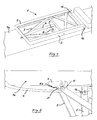
Fig. 1 eine Perspektivansicht eines Klappgestells für eine Bank in Stapelstellung, -
Fig. 2 eine vergrößerte Ansicht des Klappgestells nachFig. 1 , jedoch in Aufstellposition, -
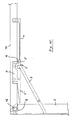
Fig. 3 eine Seitenansicht des Klappgestells mit verriegeltem Sperrelement und ausgeklappten Tischbeinen, -
Fig. 4 eine Seitenansicht analog zuFig. 3 , wobei das Sperrelement eine Hakenform aufweist, -
Fig. 5 eine Perspektivansicht ähnlich zuFig. 1 , -
Fig. 6 eine vergrößerte Perspektive mit einem Hakenelement, -
Fig. 7 eine bevorzugte Ausbildung des Führungselements in Perspektivansicht, -
Fig. 8 das Führungselement nachFig. 7 in Seitenansicht, -
Fig. 9 eine zusätzliche Ausführung des Sperrelements; -
Fig. 10 das Sperrelement nachFig. 9 , kurz vor Überführung in die Stapelposition, -
Fig. 11 eine Perspektivansicht eines Tisches mit zwei Klappgestellen, -
Fig. 12 den Klapptisch nachFig. 11 in Stapelstellung, -
Fig. 13 eine Unteransicht des Klapptisches nachFig. 11 und 12 , -
Fig. 14 den Klapptisch in umgedrehter Position, kurz vor Abklappen der Klappgestelle, und -
Fig. 15 eine ähnliche Schnittdarstellung wie inFig. 9 . - In
Fig. 1 ist ein Klappgestell 1 dargestellt, das zwei miteinander verbundene Beine 2 aufweist und an der Unterseite einer Bank- oder Tischplatte 1a befestigt ist. Hierbei ist die Stapel- oder Nichtgebrauchsstellung dargestellt. Das Klappgestell 1 kann jedoch auch nur ein (mittiges) Bein 2 aufweisen, an dem ein quer verlaufender Standholm angeordnet ist. - Dieses Klappgestell 1 für Bänke oder Tische (vgl.
Fig. 11 ) weist nahe der Unterseite der Bank oder des Tisches Schwenklager 1b für die Beine 2 auf, die insbesondere gelenkig mit Stützstreben 3 verbunden sind, welche sich in Aufstellposition bevorzugt diagonal zur Unterseite der Bank oder des Tisches erstrecken (vgl.Fig. 3 und 4 ). In Stapelposition sind die Beine 2 etwa parallel zur Unterseite der Bank oder des Tisches ausgerichtet. - In Aufstellposition sind die Beine 2 direkt oder über die mittigen Enden der Stützstreben 3, bevorzugt über einen Querbolzen 3' mit einem Sperrelement 5 verriegelt, das hier als einseitig gelagerter Schwenkhebel ausgebildet ist, der schwerkraftbetätigt "einrastet". Zum Wechsel zwischen Stapelposition und Aufstellposition (bzw. umgekehrt) sind die hier bevorzugt vorgesehenen Stützstreben 3 mit dem Querbolzen 3' in einem Führungselement 4 verschiebbar, das gemäss
Fig. 1 bis 6 bügelförmig ausgeformt ist. Dabei ist das Sperrelement 5 in einer Konsole 6 gelagert, die sich zum Führungselement 4 hin fortsetzt. Die Konsole 6 weist zum leichten Einführen des Querbolzens 3' eine Rampe 6a auf. - Wie insbesondere aus den Darstellung in
Fig. 3 ersichtlich ist, in dem sich der Schwenkhebel als Sperrelement 5 in Verriegelungsposition befindet, weist das freie Ende des Sperrelements 5 eine gewölbte Form auf, damit dieses unter Schwerkraftwirkung leicht in seine Verriegelungsstellung fällt. Der Radius dieser "konzentrischen" Wölbung entspricht dabei bevorzugt dem Abstand zum Zentrum der Lagerachse des Sperrelements 5. Dies gilt auch für die Ausführung des Sperrelements 5 gemässFig. 4 , wobei der Schwenkhebel als Haken ausgeführt ist, der den Querbolzen 3' der Stützstreben 3 umgreift. Bei beiden Ausführungen nachFig. 3 und 4 ist ersichtlich, dass der (hier jeweils links befindliche) Lagermittelpunkt des Sperrelements 5 bevorzugt auf oder nahe der Kraftwirkungslinie L der Stützstrebe 3 liegt, um so eine Übertotpunkt-Verriegelung zu bilden. Dabei nehmen die hier eingezeichneten beiden Linien (durch den jeweiligen Lagerpunkt des Sperrelements 5 und der Stützstrebe 3 zum Kontaktpunkt zwischen Querbolzen 3' und den Sperrelement 5) eine Winkel von z.B. 183° ein (von der Oberseite her gesehen). Wenn der Tisch oder die Bank um ihre Längsachse um 180° gedreht wird, kann das Sperrelement 5 gravitationsbedingt aus der Totpunkt-Verriegelung "herausfallen". - In
Fig. 5 ist ein Klappgestell 1 ähnlich wie inFig. 1 dargestellt, wobei am hier rechten Ende des Führungselements 4 bzw. der Konsole 6 ein Hakenelement 6' vorgesehen ist, das die Stützstrebe 3 zusätzlich in Stapelposition hält. Das Hakenelement 6' kann dabei in das bereits montierte Führungselement 4 eingerastet werden. Ebenso kann das Sperrelement 5 zur Halterung der Stützstrebe 3 in Aufstellposition federnd positioniert sein. InFig. 6 ist das Hakenelement 6' von der entgegengesetzten Seite vergrößert dargestellt, wobei auch eine Art Blattfeder unter dem Schwenkhebel als Sperrelement 5 oder Federnase die Halterung der Stützstrebe 3 in Aufstellposition unterstützen kann. Das Führungselement 4 kann als einteiliges Spritzgussteil ausgeführt sein, wobei die Kontaktfläche zwischen Schwenklager 1 b und Tisch- bzw. Bankplatte 1 a eine profilierte oder aufgeraute Oberfläche aufweisen kann, bevorzugt in Form von Spitzen oder Krallen. InFig. 4 ist im Bereich des Querbolzens 3' am schienenartigen Führungselement 4 eine Rastnase 4" gezeigt, die die Stützstrebe 3 beim Abbauvorgang zunächst oder kurzzeitig noch in Aufstellposition hält. Dies ist aus Sicherheitsaspekten sinnvoll, um ein Einklemmen der Finger zu vermeiden. - In
Fig. 7 ist das Führungselement 4 als Streifen ausgebildet, der somit teilflexibel aus einem einfachen Textilstreifen oder Riemen oder auch als Seil gebildet sein kann. Dies reduziert das Gewicht und die Herstellkosten. In Nähe der Konsole 6 kann solch ein Streifen geklemmt oder durch einen Widerhaken fixiert werden. Dabei kann der Riemen oder Gurt am Ende umgeschlagen und zusammengenäht sein, um so den Widerhaken sicher verankert zu sein. InFig. 8 ist in der entsprechenden Seitenansicht auch die Sperrstellung gezeigt, wobei die Einführrampe 6a für den Querbolzen 3' besonders deutlich wird, ebenso die schlanke Ausbildung des Führungselements 4. -
Fig. 9 zeigt eine ähnliche Ausführung, wobei wirkungsgleiche Bauteile das entsprechende Bezugszeichen tragen. Zusätzlich ist hier eine Verlängerung 5' des Sperrelements 5 dargestellt, so dass die Ent- oder Verriegelung zusätzlich unterstützt werden kann, insbesondere wenn eine Federbeaufschlagung ähnlich wie inFig. 6 vorgesehen ist. InFig. 10 ist die Bierbank in umgedrehter Stellung (Überkopf) gezeigt, kurz bevor das Klappgestell 1 zur Bankfläche hin geklappt wird. Hierzu kann die Verlängerung 5' zur Entriegelung in einfachster Weise niedergedrückt werden, sofern das Sperrelement 5 nicht schon ohnehin gravitationsbedingt aus seiner Sperrstellung "herausgefallen" ist. - In
Fig. 11 bis 14 ist ein Tisch mit je zwei Klappgestellen 1 dargestellt. Hierbei ist das Führungselement 4 als Führungsschiene 4', bevorzugt mit einem Hutprofil-Querschnitt ausgebildet, wobei in der Aufstellposition die Stützstreben 3 in der unteren Hälfte bewegbar sind und das Sperrelement 5 in der oberen Hälfte (zur Tischoberfläche hin) angeordnet ist. Wie insbesondere ausFig. 14 ersichtlich, sind die Schwenklager 1 b in der Ebene der Bank- oder Tischplatte 1a angeordnet und die Beine 2 weisen ein Winkelprofil auf, so dass die Bank- oder Tischplatte 1a in Stapelposition - vgl.Fig. 12 - am Außenumfang oder - rand umgriffen werden. Hierzu kann an der hier kurzen Tischseite jeweils ein Stoßschutzprofil 8 angebracht sein, so dass der Rand selbst bei grober Handhabung beim Umstapeln oder Transport gut vor Beschädigung geschützt ist. - Bevorzugt ist die Führungsschiene 4' vollständig in die Bank- oder Tischplatte 1 a vertieft eingesetzt ist, insbesondere in eine durchgehende Nut oder einen Schlitz, der zwischen zwei Tischlatten oder benachbarten Plattenteilen ohnehin vorhanden ist. Hierdurch lässt sich eine besonders geringe Stapelhöhe erzielen, wie aus
Fig. 12 erkennbar ist. InFig. 15 ist eine Schnittdarstellung durch die Längsmittelebene eines Tisches ähnlich der vorstehenden Ausführungen gezeigt. Hierbei ist das Stoßschutzprofil 8 (vgl.Fig. 12 ) an der kurzen Tischseite als Winkelprofil ausgebildet, das die Lagerung der Schwenklager 1 b und auch die Tischplatte 1a gegen Durchbiegen verstärkt. Zudem kann durch den Radius an der Biegung des Stoßschutzprofils 8 die kurze Seite des Tisches zum Tragen oder Umsetzen gut gegriffen werden. Das Sperrelement 5 weist wiederum eine Verlängerung 5' auf, die ebenfalls gut greifbar ist und zusammen mit dem Führungselement 4 in einem mittigen Schlitz (zwischen zwei Plattenteilen) der Tischplatte 1 a zumindest teilweise eingesetzt ist. Die übrigen Bauteile entsprechen den vorstehend beschriebenen Elementen.
Claims (15)
- Klappgestell für Bänke oder Tische, mit Schwenklagern (1 b) für Beine (2) an der Unterseite der Bank oder des Tisches und mit gelenkig an den Beinen (2) angreifenden Stützstreben (3), die sich in Aufstellposition bevorzugt diagonal zur Unterseite der Bank oder des Tisches erstrecken, wobei sich in Stapelposition die Beine (2) etwa parallel zur Unterseite der Bank oder des Tisches erstrecken und in Aufstellposition mit einem Sperrelement (5) verriegelt sind,
dadurch gekennzeichnet, dass
das Sperrelement (5) als einseitig gelagerter Schwenkhebel ausgebildet ist, der wenigstens ein Bein (2) schwerkraftbetätigt verriegelt. - Klappgestell nach Anspruch 1, dadurch gekennzeichnet, dass die Stützstrebe (3) mit einem freien Ende, insbesondere einem Querbolzen (3') in einem Führungselement (4) verschiebbar ist.
- Klappgestell nach Anspruch 1 oder 2, dadurch gekennzeichnet, dass das Sperrelement (5) in einer Konsole (6) gelagert ist, insbesondere mit einer Einführrampe (6a).
- Klappgestell nach einem der Ansprüche 1 bis 3, dadurch gekennzeichnet, dass das freie Ende des Sperrelements (5) gewölbt ausgeformt ist, insbesondere konzentrisch zu seiner Lagerachse.
- Klappgestell nach einem der Ansprüche 2 bis 4, dadurch gekennzeichnet, dass das Führungselement (4) als Führungsschiene (4'), insbesondere mit einem hutförmigen Querschnitt ausgebildet ist, wobei in der Aufstellposition das Ende der Stützstreben (3) in der unteren Hälfte bewegbar sind und das Sperrelement (5) in der in Aufstellposition oberen Hälfte angeordnet ist.
- Klappgestell insbesondere nach einem der Ansprüche 1 bis 5, dadurch gekennzeichnet, dass die Schwenklager (1b) in der Ebene der Bank- oder Tischplatte (1a) angeordnet sind und die Beine (2) ein Winkelprofil aufweisen, das die Bank- oder Tischplatte (1a) in Stapelposition am Außenumfang umgreift.
- Klappgestell nach einen der Ansprüche 1 bis 6, dadurch gekennzeichnet, dass das Führungselement (4) zumindest teilweise in die Bank- oder Tischplatte (1a) eingelassen ist, insbesondere vollständig in einen Schlitz zwischen Plattenteilen.
- Klappgestell nach einem der Ansprüche 1 bis 7, dadurch gekennzeichnet, dass das Sperrelement (5) als Haken ausgeführt ist.
- Klappgestell nach einem der Ansprüche 2 bis 8, dadurch gekennzeichnet, dass der Lagermittelpunkt des Sperrelements (5) bevorzugt auf oder nahe der Kraftwirkungslinie (L) der Stützstrebe (3) liegt, insbesondere in Art einer Übertotpunkt-Verriegelung.
- Klappgestell nach einem der Ansprüche 2 bis 9, dadurch gekennzeichnet, dass an der Konsole (6) ein Hakenelement (6') vorgesehen ist, das die Stützstrebe (3) bzw. eine zugehörige, als ihre Lagerachse dienende Querstange in Stapelposition hält und/oder das Sperrelement (5) zur Halterung der Stützstrebe (3) in Aufstellposition federnd positioniert.
- Klappgestell nach einem der Ansprüche 2 bis 10, dadurch gekennzeichnet, dass in Aufstellposition eine Federnase (7) das Sperrelement (5) zur Stützstrebe (3) hin beaufschlagt.
- Klappgestell nach einem der Ansprüche 2 bis 11, dadurch gekennzeichnet, dass das Führungselement (4) und/oder die Konsole (6) eine Rastnase (4") zur Lagestabilisierung der Stützstrebe (3) beim Auf- bzw. Abbauvorgang aufweist.
- Klappgestell insbesondere nach einem der Ansprüche 2 bis 12, dadurch gekennzeichnet, dass das Führungselement (4) zumindest teilflexibel ausgebildet ist, insbesondere in Art eines Metall- oder Textilstreifens oder Riemens oder Seils.
- Klappgestell nach einem der Ansprüche 1 bis 13, dadurch gekennzeichnet, dass die Konsole (6) und/oder das Schwenklager (1 b) zur Tisch- bzw. Bankplatte (1 a) hin eine profilierte oder aufgeraute Oberfläche aufweist, bevorzugt in Form von Spitzen oder Krallen.
- Klappgestell insbesondere nach einem der Ansprüche 1 bis 14, dadurch gekennzeichnet, dass das Sperrelement (5) eine hebelartige Verlängerung (5') aufweist, die ggf. zur Sperrstellung hin federbeaufschlagt ist.
Priority Applications (2)
| Application Number | Priority Date | Filing Date | Title |
|---|---|---|---|
| PL14001369T PL2792272T3 (pl) | 2013-04-16 | 2014-04-15 | Składany stelaż dla ławek lub stołów |
| HRP20211325TT HRP20211325T1 (hr) | 2013-04-16 | 2021-08-17 | Sklopivi okvir za klupu ili stol |
Applications Claiming Priority (1)
| Application Number | Priority Date | Filing Date | Title |
|---|---|---|---|
| DE202013003541.2U DE202013003541U1 (de) | 2013-04-16 | 2013-04-16 | Klappgestell für Bänke oder Tische |
Publications (2)
| Publication Number | Publication Date |
|---|---|
| EP2792272A1 true EP2792272A1 (de) | 2014-10-22 |
| EP2792272B1 EP2792272B1 (de) | 2021-06-02 |
Family
ID=50513642
Family Applications (1)
| Application Number | Title | Priority Date | Filing Date |
|---|---|---|---|
| EP14001369.9A Active EP2792272B1 (de) | 2013-04-16 | 2014-04-15 | Klappgestell für Bänke oder Tische |
Country Status (6)
| Country | Link |
|---|---|
| EP (1) | EP2792272B1 (de) |
| DE (1) | DE202013003541U1 (de) |
| DK (1) | DK2792272T3 (de) |
| ES (1) | ES2886002T3 (de) |
| HR (1) | HRP20211325T1 (de) |
| PL (1) | PL2792272T3 (de) |
Cited By (2)
| Publication number | Priority date | Publication date | Assignee | Title |
|---|---|---|---|---|
| WO2018150447A1 (ja) * | 2017-02-14 | 2018-08-23 | 株式会社コジマ | 連結支持金具 |
| CN111436747A (zh) * | 2020-05-28 | 2020-07-24 | 佛山市欧曼家具有限公司 | 一种台脚折叠机构 |
Citations (6)
| Publication number | Priority date | Publication date | Assignee | Title |
|---|---|---|---|---|
| US2579934A (en) * | 1945-09-08 | 1951-12-25 | Krasney Norman | Folding table with crosslegs and braces |
| DE1107909B (de) * | 1955-04-27 | 1961-05-31 | Albert Spieth | Zusammenklappbarer Tisch |
| FR1603974A (de) * | 1968-10-14 | 1971-06-21 | ||
| WO2000035315A1 (en) * | 1998-12-11 | 2000-06-22 | Tinga Research & Development B.V. | Fold-in corner joint |
| GB2382984A (en) * | 2001-10-25 | 2003-06-18 | Corbetta Salvatore S R L | Folding table |
| DE102006019640A1 (de) | 2006-04-25 | 2007-10-31 | Kusch & Co. Sitzmöbelwerke GmbH & Co. KG | Klapptisch |
Family Cites Families (7)
| Publication number | Priority date | Publication date | Assignee | Title |
|---|---|---|---|---|
| US1969723A (en) * | 1932-06-06 | 1934-08-14 | Collapso Table Company | Folding table |
| FR2639408B1 (fr) * | 1988-11-22 | 1994-03-04 | Simire | Dispositif de verrouillage automatique pour element articule |
| DE29604135U1 (de) * | 1996-03-06 | 1996-05-15 | Brunner GmbH, 77866 Rheinau | Klapptisch |
| DE19741743C2 (de) * | 1997-09-22 | 2000-11-16 | Kusch Co Sitzmoebel | Klapptischbeschlag |
| JP4161027B2 (ja) * | 2000-12-04 | 2008-10-08 | コクヨ株式会社 | 脚のロック装置 |
| CN2822338Y (zh) * | 2005-07-18 | 2006-10-04 | 蔡秉成 | 用于折叠桌椅的折叠支架 |
| DE202012009964U1 (de) * | 2012-10-18 | 2012-11-08 | Brunner Gmbh | Klapptisch |
-
2013
- 2013-04-16 DE DE202013003541.2U patent/DE202013003541U1/de not_active Expired - Lifetime
-
2014
- 2014-04-15 ES ES14001369T patent/ES2886002T3/es active Active
- 2014-04-15 PL PL14001369T patent/PL2792272T3/pl unknown
- 2014-04-15 DK DK14001369.9T patent/DK2792272T3/da active
- 2014-04-15 EP EP14001369.9A patent/EP2792272B1/de active Active
-
2021
- 2021-08-17 HR HRP20211325TT patent/HRP20211325T1/hr unknown
Patent Citations (6)
| Publication number | Priority date | Publication date | Assignee | Title |
|---|---|---|---|---|
| US2579934A (en) * | 1945-09-08 | 1951-12-25 | Krasney Norman | Folding table with crosslegs and braces |
| DE1107909B (de) * | 1955-04-27 | 1961-05-31 | Albert Spieth | Zusammenklappbarer Tisch |
| FR1603974A (de) * | 1968-10-14 | 1971-06-21 | ||
| WO2000035315A1 (en) * | 1998-12-11 | 2000-06-22 | Tinga Research & Development B.V. | Fold-in corner joint |
| GB2382984A (en) * | 2001-10-25 | 2003-06-18 | Corbetta Salvatore S R L | Folding table |
| DE102006019640A1 (de) | 2006-04-25 | 2007-10-31 | Kusch & Co. Sitzmöbelwerke GmbH & Co. KG | Klapptisch |
Cited By (2)
| Publication number | Priority date | Publication date | Assignee | Title |
|---|---|---|---|---|
| WO2018150447A1 (ja) * | 2017-02-14 | 2018-08-23 | 株式会社コジマ | 連結支持金具 |
| CN111436747A (zh) * | 2020-05-28 | 2020-07-24 | 佛山市欧曼家具有限公司 | 一种台脚折叠机构 |
Also Published As
| Publication number | Publication date |
|---|---|
| ES2886002T3 (es) | 2021-12-16 |
| PL2792272T3 (pl) | 2021-12-13 |
| DK2792272T3 (da) | 2021-08-30 |
| DE202013003541U1 (de) | 2014-04-22 |
| EP2792272B1 (de) | 2021-06-02 |
| HRP20211325T1 (hr) | 2021-12-10 |
Similar Documents
| Publication | Publication Date | Title |
|---|---|---|
| DE102013222651B4 (de) | Vorrichtung zum Sichern von Ladegut in einem Laderaum sowie Befestigungselement hierfür | |
| DE202017100661U1 (de) | Vorrichtung zum Aufstellen einer Leiter oder eines Tritts auf einer Treppe | |
| DE102010017535B4 (de) | Befestigungseinrichtung zum zumindest teilweisen Sichern eines ersten und eines zweiten Frachtstücks | |
| EP0580960A1 (de) | Trittplatte für Leitern | |
| EP3156279B1 (de) | Fahrzeug für den transport von transportgütern | |
| DE1780395C3 (de) | Verschlußvorrichtung für klappbare Bordwände von Ladebrücken an Lastkraftwagen o.dgl | |
| DE202006003535U1 (de) | Vorrichtung zum Klappen einer Tischplatte | |
| EP2792272B1 (de) | Klappgestell für Bänke oder Tische | |
| DE102009039042A1 (de) | Sicherungslasche | |
| AT506979A1 (de) | Gepäckablage für ein passagierflugzeug | |
| DE202007012830U1 (de) | Varioträger | |
| DE102018124600B4 (de) | Möbelauszug | |
| DE3020064A1 (de) | Vorrichtung zum verriegeln der schwenkbaren eckpfosten von ladeplattformen (klappflats) | |
| DE102012201204A1 (de) | Verriegelungssystem für eine Tischtennisplatte | |
| DE202006000455U1 (de) | Geländeranordnung | |
| DE202014100556U1 (de) | Steiggerät mit Verriegelungsmechanismus | |
| EP2640557B1 (de) | Arbeitstisch, insbesondere für den werkstattbereich | |
| DE102014014310B4 (de) | Klappgestell für Bänke oder Tische | |
| DE202008010622U1 (de) | Geländer für Arbeits- und Hubarbeitsbühnen mit einem Klappmechanismus zum Aufrichten oder Ablegen | |
| DE19738679C1 (de) | Schiebestück mit Sicherung | |
| DE202015101671U1 (de) | Gurtspanner | |
| DE3132294C2 (de) | An einer Vorrichtung insbesondere an einem Fahrzeug angebrachte Leiter | |
| EP2446772A1 (de) | Klapptisch | |
| DE202020002233U1 (de) | Einsteighilfe | |
| DE102008039198B4 (de) | Verbindungseinrichtung zur schwenkbaren Verbindung zweier Bauteile, insbesondere eines Zeltes |
Legal Events
| Date | Code | Title | Description |
|---|---|---|---|
| PUAI | Public reference made under article 153(3) epc to a published international application that has entered the european phase |
Free format text: ORIGINAL CODE: 0009012 |
|
| 17P | Request for examination filed |
Effective date: 20140415 |
|
| AK | Designated contracting states |
Kind code of ref document: A1 Designated state(s): AL AT BE BG CH CY CZ DE DK EE ES FI FR GB GR HR HU IE IS IT LI LT LU LV MC MK MT NL NO PL PT RO RS SE SI SK SM TR |
|
| AX | Request for extension of the european patent |
Extension state: BA ME |
|
| R17P | Request for examination filed (corrected) |
Effective date: 20150422 |
|
| RBV | Designated contracting states (corrected) |
Designated state(s): AL AT BE BG CH CY CZ DE DK EE ES FI FR GB GR HR HU IE IS IT LI LT LU LV MC MK MT NL NO PL PT RO RS SE SI SK SM TR |
|
| 17Q | First examination report despatched |
Effective date: 20151002 |
|
| STAA | Information on the status of an ep patent application or granted ep patent |
Free format text: STATUS: EXAMINATION IS IN PROGRESS |
|
| APBK | Appeal reference recorded |
Free format text: ORIGINAL CODE: EPIDOSNREFNE |
|
| APBN | Date of receipt of notice of appeal recorded |
Free format text: ORIGINAL CODE: EPIDOSNNOA2E |
|
| APBR | Date of receipt of statement of grounds of appeal recorded |
Free format text: ORIGINAL CODE: EPIDOSNNOA3E |
|
| APAF | Appeal reference modified |
Free format text: ORIGINAL CODE: EPIDOSCREFNE |
|
| APAF | Appeal reference modified |
Free format text: ORIGINAL CODE: EPIDOSCREFNE |
|
| APBX | Invitation to file observations in appeal sent |
Free format text: ORIGINAL CODE: EPIDOSNOBA2E |
|
| APBZ | Receipt of observations in appeal recorded |
Free format text: ORIGINAL CODE: EPIDOSNOBA4E |
|
| APAQ | Information on invitation to file observation in appeal modified |
Free format text: ORIGINAL CODE: EPIDOSCOBA2E |
|
| APBH | Information on receipt of observation in appeal deleted |
Free format text: ORIGINAL CODE: EPIDOSDOBA4E |
|
| APBZ | Receipt of observations in appeal recorded |
Free format text: ORIGINAL CODE: EPIDOSNOBA4E |
|
| APBT | Appeal procedure closed |
Free format text: ORIGINAL CODE: EPIDOSNNOA9E |
|
| GRAP | Despatch of communication of intention to grant a patent |
Free format text: ORIGINAL CODE: EPIDOSNIGR1 |
|
| STAA | Information on the status of an ep patent application or granted ep patent |
Free format text: STATUS: GRANT OF PATENT IS INTENDED |
|
| INTG | Intention to grant announced |
Effective date: 20201203 |
|
| GRAS | Grant fee paid |
Free format text: ORIGINAL CODE: EPIDOSNIGR3 |
|
| RAP3 | Party data changed (applicant data changed or rights of an application transferred) |
Owner name: WASSERMANN, CHRISTIAN Owner name: KAISER, THOMAS |
|
| RIN1 | Information on inventor provided before grant (corrected) |
Inventor name: WASSERMANN, CHRISTIAN Inventor name: KAISER, THOMAS |
|
| GRAA | (expected) grant |
Free format text: ORIGINAL CODE: 0009210 |
|
| STAA | Information on the status of an ep patent application or granted ep patent |
Free format text: STATUS: THE PATENT HAS BEEN GRANTED |
|
| REG | Reference to a national code |
Ref country code: CH Ref legal event code: EP |
|
| AK | Designated contracting states |
Kind code of ref document: B1 Designated state(s): AL AT BE BG CH CY CZ DE DK EE ES FI FR GB GR HR HU IE IS IT LI LT LU LV MC MK MT NL NO PL PT RO RS SE SI SK SM TR |
|
| REG | Reference to a national code |
Ref country code: GB Ref legal event code: FG4D Free format text: NOT ENGLISH |
|
| REG | Reference to a national code |
Ref country code: AT Ref legal event code: REF Ref document number: 1397634 Country of ref document: AT Kind code of ref document: T Effective date: 20210615 |
|
| REG | Reference to a national code |
Ref country code: IE Ref legal event code: FG4D Free format text: LANGUAGE OF EP DOCUMENT: GERMAN |
|
| REG | Reference to a national code |
Ref country code: DE Ref legal event code: R096 Ref document number: 502014015630 Country of ref document: DE |
|
| REG | Reference to a national code |
Ref country code: HR Ref legal event code: TUEP Ref document number: P20211325T Country of ref document: HR |
|
| REG | Reference to a national code |
Ref country code: FI Ref legal event code: FGE |
|
| REG | Reference to a national code |
Ref country code: DK Ref legal event code: T3 Effective date: 20210825 |
|
| REG | Reference to a national code |
Ref country code: NL Ref legal event code: FP |
|
| REG | Reference to a national code |
Ref country code: SE Ref legal event code: TRGR |
|
| REG | Reference to a national code |
Ref country code: LT Ref legal event code: MG9D |
|
| REG | Reference to a national code |
Ref country code: NO Ref legal event code: T2 Effective date: 20210602 |
|
| PG25 | Lapsed in a contracting state [announced via postgrant information from national office to epo] |
Ref country code: LT Free format text: LAPSE BECAUSE OF FAILURE TO SUBMIT A TRANSLATION OF THE DESCRIPTION OR TO PAY THE FEE WITHIN THE PRESCRIBED TIME-LIMIT Effective date: 20210602 Ref country code: BG Free format text: LAPSE BECAUSE OF FAILURE TO SUBMIT A TRANSLATION OF THE DESCRIPTION OR TO PAY THE FEE WITHIN THE PRESCRIBED TIME-LIMIT Effective date: 20210902 |
|
| REG | Reference to a national code |
Ref country code: GR Ref legal event code: EP Ref document number: 20210402300 Country of ref document: GR Effective date: 20211013 |
|
| PG25 | Lapsed in a contracting state [announced via postgrant information from national office to epo] |
Ref country code: LV Free format text: LAPSE BECAUSE OF FAILURE TO SUBMIT A TRANSLATION OF THE DESCRIPTION OR TO PAY THE FEE WITHIN THE PRESCRIBED TIME-LIMIT Effective date: 20210602 Ref country code: RS Free format text: LAPSE BECAUSE OF FAILURE TO SUBMIT A TRANSLATION OF THE DESCRIPTION OR TO PAY THE FEE WITHIN THE PRESCRIBED TIME-LIMIT Effective date: 20210602 |
|
| REG | Reference to a national code |
Ref country code: HR Ref legal event code: T1PR Ref document number: P20211325 Country of ref document: HR |
|
| REG | Reference to a national code |
Ref country code: ES Ref legal event code: FG2A Ref document number: 2886002 Country of ref document: ES Kind code of ref document: T3 Effective date: 20211216 |
|
| PG25 | Lapsed in a contracting state [announced via postgrant information from national office to epo] |
Ref country code: RO Free format text: LAPSE BECAUSE OF FAILURE TO SUBMIT A TRANSLATION OF THE DESCRIPTION OR TO PAY THE FEE WITHIN THE PRESCRIBED TIME-LIMIT Effective date: 20210602 Ref country code: PT Free format text: LAPSE BECAUSE OF FAILURE TO SUBMIT A TRANSLATION OF THE DESCRIPTION OR TO PAY THE FEE WITHIN THE PRESCRIBED TIME-LIMIT Effective date: 20211004 Ref country code: EE Free format text: LAPSE BECAUSE OF FAILURE TO SUBMIT A TRANSLATION OF THE DESCRIPTION OR TO PAY THE FEE WITHIN THE PRESCRIBED TIME-LIMIT Effective date: 20210602 Ref country code: SK Free format text: LAPSE BECAUSE OF FAILURE TO SUBMIT A TRANSLATION OF THE DESCRIPTION OR TO PAY THE FEE WITHIN THE PRESCRIBED TIME-LIMIT Effective date: 20210602 Ref country code: SM Free format text: LAPSE BECAUSE OF FAILURE TO SUBMIT A TRANSLATION OF THE DESCRIPTION OR TO PAY THE FEE WITHIN THE PRESCRIBED TIME-LIMIT Effective date: 20210602 |
|
| REG | Reference to a national code |
Ref country code: DE Ref legal event code: R097 Ref document number: 502014015630 Country of ref document: DE |
|
| PLBE | No opposition filed within time limit |
Free format text: ORIGINAL CODE: 0009261 |
|
| STAA | Information on the status of an ep patent application or granted ep patent |
Free format text: STATUS: NO OPPOSITION FILED WITHIN TIME LIMIT |
|
| REG | Reference to a national code |
Ref country code: HR Ref legal event code: ODRP Ref document number: P20211325 Country of ref document: HR Payment date: 20220401 Year of fee payment: 9 |
|
| 26N | No opposition filed |
Effective date: 20220303 |
|
| PG25 | Lapsed in a contracting state [announced via postgrant information from national office to epo] |
Ref country code: AL Free format text: LAPSE BECAUSE OF FAILURE TO SUBMIT A TRANSLATION OF THE DESCRIPTION OR TO PAY THE FEE WITHIN THE PRESCRIBED TIME-LIMIT Effective date: 20210602 |
|
| PGFP | Annual fee paid to national office [announced via postgrant information from national office to epo] |
Ref country code: TR Payment date: 20220330 Year of fee payment: 9 |
|
| PGFP | Annual fee paid to national office [announced via postgrant information from national office to epo] |
Ref country code: SE Payment date: 20220426 Year of fee payment: 9 Ref country code: NO Payment date: 20220420 Year of fee payment: 9 Ref country code: IT Payment date: 20220421 Year of fee payment: 9 Ref country code: HR Payment date: 20220401 Year of fee payment: 9 Ref country code: GB Payment date: 20220426 Year of fee payment: 9 Ref country code: ES Payment date: 20220513 Year of fee payment: 9 Ref country code: DK Payment date: 20220421 Year of fee payment: 9 Ref country code: CZ Payment date: 20220414 Year of fee payment: 9 |
|
| PGFP | Annual fee paid to national office [announced via postgrant information from national office to epo] |
Ref country code: PL Payment date: 20220401 Year of fee payment: 9 Ref country code: GR Payment date: 20220420 Year of fee payment: 9 Ref country code: FI Payment date: 20220419 Year of fee payment: 9 Ref country code: BE Payment date: 20220427 Year of fee payment: 9 |
|
| PG25 | Lapsed in a contracting state [announced via postgrant information from national office to epo] |
Ref country code: MC Free format text: LAPSE BECAUSE OF FAILURE TO SUBMIT A TRANSLATION OF THE DESCRIPTION OR TO PAY THE FEE WITHIN THE PRESCRIBED TIME-LIMIT Effective date: 20210602 Ref country code: LU Free format text: LAPSE BECAUSE OF NON-PAYMENT OF DUE FEES Effective date: 20220415 |
|
| REG | Reference to a national code |
Ref country code: FR Ref legal event code: PLFP Year of fee payment: 10 |
|
| PG25 | Lapsed in a contracting state [announced via postgrant information from national office to epo] |
Ref country code: IE Free format text: LAPSE BECAUSE OF NON-PAYMENT OF DUE FEES Effective date: 20220415 |
|
| PGFP | Annual fee paid to national office [announced via postgrant information from national office to epo] |
Ref country code: NL Payment date: 20230413 Year of fee payment: 10 |
|
| PGFP | Annual fee paid to national office [announced via postgrant information from national office to epo] |
Ref country code: FR Payment date: 20230413 Year of fee payment: 10 Ref country code: CH Payment date: 20230502 Year of fee payment: 10 |
|
| PGFP | Annual fee paid to national office [announced via postgrant information from national office to epo] |
Ref country code: AT Payment date: 20230413 Year of fee payment: 10 |
|
| REG | Reference to a national code |
Ref country code: HR Ref legal event code: PBON Ref document number: P20211325 Country of ref document: HR Effective date: 20230415 |
|
| REG | Reference to a national code |
Ref country code: NO Ref legal event code: MMEP |
|
| REG | Reference to a national code |
Ref country code: DK Ref legal event code: EBP Effective date: 20230430 |
|
| REG | Reference to a national code |
Ref country code: SE Ref legal event code: EUG |
|
| GBPC | Gb: european patent ceased through non-payment of renewal fee |
Effective date: 20230415 |
|
| REG | Reference to a national code |
Ref country code: BE Ref legal event code: MM Effective date: 20230430 |
|
| PG25 | Lapsed in a contracting state [announced via postgrant information from national office to epo] |
Ref country code: GB Free format text: LAPSE BECAUSE OF NON-PAYMENT OF DUE FEES Effective date: 20230415 Ref country code: GR Free format text: LAPSE BECAUSE OF NON-PAYMENT OF DUE FEES Effective date: 20231110 |
|
| PG25 | Lapsed in a contracting state [announced via postgrant information from national office to epo] |
Ref country code: SE Free format text: LAPSE BECAUSE OF NON-PAYMENT OF DUE FEES Effective date: 20230416 Ref country code: NO Free format text: LAPSE BECAUSE OF NON-PAYMENT OF DUE FEES Effective date: 20230430 Ref country code: HR Free format text: LAPSE BECAUSE OF NON-PAYMENT OF DUE FEES Effective date: 20230415 Ref country code: GR Free format text: LAPSE BECAUSE OF NON-PAYMENT OF DUE FEES Effective date: 20231110 Ref country code: GB Free format text: LAPSE BECAUSE OF NON-PAYMENT OF DUE FEES Effective date: 20230415 Ref country code: FI Free format text: LAPSE BECAUSE OF NON-PAYMENT OF DUE FEES Effective date: 20230415 Ref country code: CZ Free format text: LAPSE BECAUSE OF NON-PAYMENT OF DUE FEES Effective date: 20230415 |
|
| PG25 | Lapsed in a contracting state [announced via postgrant information from national office to epo] |
Ref country code: BE Free format text: LAPSE BECAUSE OF NON-PAYMENT OF DUE FEES Effective date: 20230430 |
|
| PG25 | Lapsed in a contracting state [announced via postgrant information from national office to epo] |
Ref country code: HU Free format text: LAPSE BECAUSE OF FAILURE TO SUBMIT A TRANSLATION OF THE DESCRIPTION OR TO PAY THE FEE WITHIN THE PRESCRIBED TIME-LIMIT; INVALID AB INITIO Effective date: 20140415 |
|
| PG25 | Lapsed in a contracting state [announced via postgrant information from national office to epo] |
Ref country code: MK Free format text: LAPSE BECAUSE OF FAILURE TO SUBMIT A TRANSLATION OF THE DESCRIPTION OR TO PAY THE FEE WITHIN THE PRESCRIBED TIME-LIMIT Effective date: 20210602 Ref country code: IT Free format text: LAPSE BECAUSE OF NON-PAYMENT OF DUE FEES Effective date: 20230415 Ref country code: DK Free format text: LAPSE BECAUSE OF NON-PAYMENT OF DUE FEES Effective date: 20230430 Ref country code: CY Free format text: LAPSE BECAUSE OF FAILURE TO SUBMIT A TRANSLATION OF THE DESCRIPTION OR TO PAY THE FEE WITHIN THE PRESCRIBED TIME-LIMIT Effective date: 20210602 |
|
| REG | Reference to a national code |
Ref country code: ES Ref legal event code: FD2A Effective date: 20240604 |
|
| PG25 | Lapsed in a contracting state [announced via postgrant information from national office to epo] |
Ref country code: ES Free format text: LAPSE BECAUSE OF NON-PAYMENT OF DUE FEES Effective date: 20230416 |
|
| PG25 | Lapsed in a contracting state [announced via postgrant information from national office to epo] |
Ref country code: ES Free format text: LAPSE BECAUSE OF NON-PAYMENT OF DUE FEES Effective date: 20230416 |
|
| PG25 | Lapsed in a contracting state [announced via postgrant information from national office to epo] |
Ref country code: MT Free format text: LAPSE BECAUSE OF FAILURE TO SUBMIT A TRANSLATION OF THE DESCRIPTION OR TO PAY THE FEE WITHIN THE PRESCRIBED TIME-LIMIT Effective date: 20210602 |
|
| REG | Reference to a national code |
Ref country code: CH Ref legal event code: PL |
|
| REG | Reference to a national code |
Ref country code: NL Ref legal event code: MM Effective date: 20240501 |
|
| REG | Reference to a national code |
Ref country code: AT Ref legal event code: MM01 Ref document number: 1397634 Country of ref document: AT Kind code of ref document: T Effective date: 20240415 |
|
| PG25 | Lapsed in a contracting state [announced via postgrant information from national office to epo] |
Ref country code: NL Free format text: LAPSE BECAUSE OF NON-PAYMENT OF DUE FEES Effective date: 20240501 Ref country code: PL Free format text: LAPSE BECAUSE OF NON-PAYMENT OF DUE FEES Effective date: 20230415 |
|
| PG25 | Lapsed in a contracting state [announced via postgrant information from national office to epo] |
Ref country code: FR Free format text: LAPSE BECAUSE OF NON-PAYMENT OF DUE FEES Effective date: 20240430 |
|
| PG25 | Lapsed in a contracting state [announced via postgrant information from national office to epo] |
Ref country code: AT Free format text: LAPSE BECAUSE OF NON-PAYMENT OF DUE FEES Effective date: 20240415 |
|
| PG25 | Lapsed in a contracting state [announced via postgrant information from national office to epo] |
Ref country code: PL Free format text: LAPSE BECAUSE OF NON-PAYMENT OF DUE FEES Effective date: 20230415 Ref country code: NL Free format text: LAPSE BECAUSE OF NON-PAYMENT OF DUE FEES Effective date: 20240501 Ref country code: FR Free format text: LAPSE BECAUSE OF NON-PAYMENT OF DUE FEES Effective date: 20240430 Ref country code: AT Free format text: LAPSE BECAUSE OF NON-PAYMENT OF DUE FEES Effective date: 20240415 Ref country code: CH Free format text: LAPSE BECAUSE OF NON-PAYMENT OF DUE FEES Effective date: 20240430 |
|
| REG | Reference to a national code |
Ref country code: DE Ref legal event code: R081 Ref document number: 502014015630 Country of ref document: DE Owner name: FIRE FRIENDS GMBH & CO. KG, DE Free format text: FORMER OWNERS: KAISER, THOMAS, 87463 DIETMANNSRIED, DE; WASSERMANN, CHRISTIAN, 87640 BIESSENHOFEN, DE |
|
| PG25 | Lapsed in a contracting state [announced via postgrant information from national office to epo] |
Ref country code: TR Free format text: LAPSE BECAUSE OF NON-PAYMENT OF DUE FEES Effective date: 20230415 |
|
| PGFP | Annual fee paid to national office [announced via postgrant information from national office to epo] |
Ref country code: DE Payment date: 20260505 Year of fee payment: 13 |