EP2790068A2 - Escapement system for a balance-hairspring resonator - Google Patents
Escapement system for a balance-hairspring resonator Download PDFInfo
- Publication number
- EP2790068A2 EP2790068A2 EP14157942.5A EP14157942A EP2790068A2 EP 2790068 A2 EP2790068 A2 EP 2790068A2 EP 14157942 A EP14157942 A EP 14157942A EP 2790068 A2 EP2790068 A2 EP 2790068A2
- Authority
- EP
- European Patent Office
- Prior art keywords
- wheel
- teeth
- timepiece
- fixed
- pin
- Prior art date
- Legal status (The legal status is an assumption and is not a legal conclusion. Google has not performed a legal analysis and makes no representation as to the accuracy of the status listed.)
- Granted
Links
Images


Classifications
-
- G—PHYSICS
- G04—HOROLOGY
- G04B—MECHANICALLY-DRIVEN CLOCKS OR WATCHES; MECHANICAL PARTS OF CLOCKS OR WATCHES IN GENERAL; TIME PIECES USING THE POSITION OF THE SUN, MOON OR STARS
- G04B15/00—Escapements
- G04B15/14—Component parts or constructional details, e.g. construction of the lever or the escape wheel
-
- G—PHYSICS
- G04—HOROLOGY
- G04B—MECHANICALLY-DRIVEN CLOCKS OR WATCHES; MECHANICAL PARTS OF CLOCKS OR WATCHES IN GENERAL; TIME PIECES USING THE POSITION OF THE SUN, MOON OR STARS
- G04B15/00—Escapements
-
- G—PHYSICS
- G04—HOROLOGY
- G04B—MECHANICALLY-DRIVEN CLOCKS OR WATCHES; MECHANICAL PARTS OF CLOCKS OR WATCHES IN GENERAL; TIME PIECES USING THE POSITION OF THE SUN, MOON OR STARS
- G04B15/00—Escapements
- G04B15/06—Free escapements
- G04B15/08—Lever escapements
-
- G—PHYSICS
- G04—HOROLOGY
- G04B—MECHANICALLY-DRIVEN CLOCKS OR WATCHES; MECHANICAL PARTS OF CLOCKS OR WATCHES IN GENERAL; TIME PIECES USING THE POSITION OF THE SUN, MOON OR STARS
- G04B17/00—Mechanisms for stabilising frequency
- G04B17/20—Compensation of mechanisms for stabilising frequency
- G04B17/28—Compensation of mechanisms for stabilising frequency for the effect of unbalance of the weights, e.g. tourbillon
- G04B17/285—Tourbillons or carrousels
Definitions
- the invention relates to an exhaust system for a balance-spring resonator and, more particularly for such a high-amplitude resonator.
- An exhaust system of a timepiece is intended to maintain and count the oscillations of the balance of a balance-spring resonator. To do this, it receives the energy dispensed by a barrel and at the end of the chain by a wheel of seconds in order to periodically let out a parcel of this motive energy to restore to the resonator the energy lost in passive resistances (for example the friction ), this resonator comprising a flywheel called pendulum on the axis of which is fixed a spiral spring called spiral.
- the horological technique tends to increase the energy of the balance-spring resonator in order to improve its precision and its resistance to shocks, thanks to the increase in the inertia J of the balance and / or to the increase of the oscillation frequency f of the pendulum.
- the increase of these parameters poses great difficulties.
- the object of the present invention is to overcome all or part of the aforementioned drawbacks by proposing an alternative exhaust system for a spring-balance resonator which allows the increase of the mechanical energy E m of said resonator while avoiding the pitfalls mentioned above. -above.
- the invention relates to a timepiece comprising a resonator formed by a balance associated with a hairspring and cooperating with an exhaust system characterized in that the exhaust system comprises a mobile escapement wheel arranged coaxially with the pendulum and driven by the wheel of the timepiece, a first fixed wheel having a first toothing and a second fixed wheel having a second toothing, the first fixed wheel being disposed inside of the second fixed wheel in the same plane leaving a space forming a closed channel, said first and second fixed wheels being disposed coaxially with the movable escape wheel and a device for fixing the outer end of the spiral comprising a part articulated by relative to the mobile escapement wheel and arranged to ensure, according to the state of arming of the spiral, a radial displacement of the ladi the outer end between the said first and second teeth to maintain the resonator and distribute its movement to the wheel of the timepiece
- the invention relates to a timepiece comprising a resonator formed by a rocker associated with a hairspring and cooperating with an exhaust system characterized in that the exhaust system comprises an escape wheel.
- mobile disposed coaxially with the balance wheel and driven by the wheel of the timepiece, a first fixed wheel having a first toothing and a second fixed wheel which, mounted above the first wheel, has a second toothing, the first toothing comprising an inner diameter smaller than that of the second toothing, said first and second fixed wheels being arranged coaxially with the movable escapement wheel and a device for fixing the outer end of the spiral comprising a part articulated with respect to the wheel of mobile exhaust and arranged to ensure, according to the state of winding of the hairspring, a radial displacement of said end ex between said first and second teeth to maintain the resonator and distribute its movement to the wheel of the timepiece.
- the invention relates to a timepiece comprising a resonator formed by a balance associated with a hairspring and cooperating with an exhaust system characterized in that the exhaust system comprises an escape wheel mobile arranged coaxially with the balance wheel and driven by the gear of the timepiece, a first series of teeth and a second series of teeth, the series of teeth are distributed circularly and coaxially with the mobile escapement wheel, the first series of teeth being distributed circularly at a smaller radius than that of the second series of teeth in the same plane, and a device for fixing the outer end of the spiral comprising a part hinged to the movable escape wheel and arranged to ensuring, according to the state of winding of the hairspring, a radial displacement of said outer end between said first and second series of teeth to maintain the resonator and distribute its movement to the wheel of the timepiece.
- the articulated part relative to the movable escape wheel preferably comprises at least one pin to cooperate with the first and second sets of teeth or series of teeth.
- the articulated part of the fixing device comprises a first arm at the end of which is fixed a first pin arranged to cooperate with the first toothing of the first fixed wheel, and a second arm to the end of which is fixed a second pin arranged to cooperate with the second toothing of the second fixed wheel, each arm can be offset in height.
- the exhaust system proposes, advantageously according to the invention, increasing the amplitude A oscillation of the balance in order to increase the mechanical energy E m of the resonator.
- increasing the amplitude A of the oscillation of the balance will have a greater influence because the amplitude A is squared.
- the present invention allows to maintain directly the spiral and not the balance as in the traditional exhausts.
- the exhaust system can be triggered by the movement of the hairspring, for example by the radial displacement of its outer end.
- FIG. figure 1 is a perspective view of an oscillator according to the invention, that is to say an exhaust system 18 coupled to a balance-spring resonator-spiral.
- the resonator 15 according to the invention comprises a balance 1 associated with a spiral 2.
- the spiral 2 is represented only by a limited number of turns. However, the spiral 2 may, of course, have a greater number of turns without departing from the scope of the invention.
- the inner end 50 of the hairspring 2 is fixed on a shaft 43 such as, for example, by means of a ferrule (better visible in the figure 9 ) come form.
- the balance 1 is also fixed on the shaft 43.
- the exhaust system 18 comprises a movable escapement wheel 3 disposed coaxially with respect to the resonator 15.
- the mobile escapement wheel 3 is driven by a wheel of seconds 4 belonging to the wheel of the timepiece which is engaged with a barrel providing the driving force of the timepiece.
- the exhaust system 18 further comprises a first fixed wheel 5 having an external toothing 6 and a second fixed wheel 7 having an internal toothing 8.
- the two fixed wheels 5, 7 of the exhaust system 18 are arranged coaxially with the mobile escapement wheel 3 and fixed to a fixed point of the timepiece, for example its plate, by means of screws 16 and 17.
- the first and second fixed wheels 5 and 7 are arranged in the same plane, the first wheel 5 being placed inside the second wheel 7 leaving a space, forming a channel closed 56 substantially crenellated and symmetrical, wherein an ankle 14 can move.
- the mobile escapement wheel 3 is provided with a device 9 for fixing the outer end 10 of the spiral 2 to arm the latter.
- the fixing device 9 is arranged to ensure, according to the state of winding of the hairspring 2, a radial displacement of the outer end 10, the latter being brought to cooperate alternately with the toothing 6 of one then the toothing 8 of the other of the first 5 and second 7 fixed wheels. It is understood that this radial displacement allows the exhaust system 18 to ensure the maintenance of the resonator 15 and the escape of the seconds wheel 4.
- FIG. 9 A cut of principle exerted on the figure 1 is shown in figure 9 .
- the mobile escapement wheel 3 is associated with an internal element 40 that has come into shape in the example of the figure 9 .
- the mobile escapement wheel assembly 3 - internal element 40 is made rotatable relative to a fixed point 42 of the timepiece, such as its plate, preferably using a ball bearing 41 .
- the fixing device 9 comprises a bar 11 articulated to ensure the radial displacement of the outer end 10 of the spiral 2.
- the bar 11 is mounted, on the one hand, on a pivoting pin 12 carried by the mobile escapement wheel 3 and, secondly, on the outer end 10 of the spiral 2.
- the outer end 10 of the hairspring 2 is integral with the peg 14 which can evolve in the closed channel 56 substantially crenellated and symmetrical and being adapted to be fitted to the free end 13 of the bar 11.
- the ankle 14 is formed according to the same material as the spiral 2 or ruby-based.
- the figure 7 shows that the essential object of the present invention is achieved, namely the increase of the amplitude A of the oscillation of the balance.
- the amplitude A of the balance 1 is of the order of 550 degrees, which greatly exceeds the 320 degrees reached by an anchor type exhaust system Swiss.
- this increase in amplitude A is achieved by maintaining the resonator 15, that is to say by supplying energy, directly by the spring 2 by pulling its outer end 10 and by not the balance 1 itself as in traditional Swiss anchor escapements.
- it is therefore no longer necessary to mount a plate on the balance shaft.
- the figure 8 is a graph comparing the couples transmitted in milli-milli-millimeters (mNmm), on the one hand, to the resonator 15 equipping the present invention (E-pattern) and, on the other hand, to an energy equilibrium balance-spring resonator equipping an exhaust system of the Swiss anchor type (route F). It can be seen that the torque imparted to the resonator 15 according to the invention during the angle during which it is applied is much larger (maximum of the order of 0.25 mNmm) than that conferred on the spring balance resonator.
- the figure 7 shows again that the angles ⁇ and ⁇ illustrated respectively on the figures 4 and 6 are substantially equal to each other at 30 degrees and are traveled ( ⁇ + ⁇ ) in 0.25 seconds for a frequency substantially equal to 4 Hz. It follows that the mobile escapement wheel 3 makes a turn in substantially 1.5 seconds. It is thus understood that this same rotational movement affects the resonator 15 which rotates in the manner of a vortex with a similar effect, that is to say that this rotation for averaging and correcting the effects of gravity on the resonator 15.
- the exhaust system 18 makes it possible to correct the effects of gravity. It is also understood that the exhaust system 18 offers the guarantee of self-starting a high frequency movement even with a high rigidity, the increase in stability and the quality factor in the absence of shocks. maintenance, elimination of the risk of rebat and overturning that are intrinsic to the architecture, improving the performance of the exhaust functions because the losses are due solely to the friction in the pivots and a moving and reducing the number of components to be oiled by removing the anchor.
- FIG. figure 10 a second embodiment of the exhaust system 21 according to the invention is illustrated in FIG. figure 10 .
- the mobile escapement wheel 3 of the first embodiment is replaced by a toothing 19 formed on the outside of a cage 45.
- the cage 45 encloses a resonator 20 which is of the same type as the resonator 15 of the first embodiment.
- the rocker 1 and the inner end 50 of the hairspring 2 are fixed on a shaft 46 pivoting between the walls 47 and 48 of the cage 45.
- the cage 45 of the exhaust system 21 is pivotally mounted between a bridge 49 and the center of the first fixed wheel 5.
- FIGS. Figures 11 to 13 A third embodiment of exhaust system 22 according to the invention is illustrated in FIGS. Figures 11 to 13 .
- the exhaust system 22 differs from the two previous embodiments in that the first and second fixed wheels 5 and 7 are made in one piece.
- the resonator 23 of the third embodiment is of the same type as the resonator 15, of the first two embodiments.
- the balance 1 equipped with balancing screw 70 and connected to the shaft 43 by means of four arms 71.
- the shaft 43 is pivotally mounted between the bridge 44 and a bearing 72 secured to a block 51 which incorporates in one piece the outer teeth 6 and inner teeth 8, formed, in the first two embodiments, by the fixed wheels 5 and 7.
- the balance 1 is associated with the spiral 24 having more turns than the spiral 2 of the first embodiment and the end of the inner coil 50 is fixed to the shaft 43 for example by means of a ferrule.
- the end of the outer turn 10 is attached to the pin 14 fixed to the free end 13 of the bar 11, the latter being hinged to the pin 12 carried by the mobile escapement wheel 3 as for the first embodiment .
- the mobile escapement wheel 3 is provided with a set of teeth 73 in engagement with the seconds wheel 4 also as for the first embodiment and is associated with the internal element 40 of a ball bearing 41 whose element external 42 is secured to the block 51 fixed to a fixed point of the timepiece, such as its platinum.
- a fourth embodiment according to the invention is illustrated in the figure 14 .
- the resonator 25 of the fourth embodiment is of the same type as the resonator 15, 20, 23 of the first three embodiments. Contrary to what has been shown in the three embodiments above in which the first and second fixed wheels 5, 7 were located in the same plane, in the fourth embodiment, the exhaust system 25 includes first and second fixed wheels 70, 71 which are placed one over the other.
- the first and second fixed wheels 70, 71 respectively comprise first and second inner teeth 72, 73 which are superposed.
- the fixing device 74 differs from that 9 of the first three embodiments.
- the fixing device 74 comprises a rocker 75 articulated on a stud 12 carried by the mobile escapement wheel 3.
- the rocker 75 carries a first arm 76 at the end of which are fixed the outer end 10 of the spiral 2 and a first pin 77 arranged to cooperate with the first teeth 72 of the first fixed wheel 70.
- the rocker 75 still carries a second arm 78 at the end of which is fixed a second pin 79 arranged to cooperate with the second teeth 73 of the second fixed wheel 71.
- each pin 77, 79 is formed according to the same material as the spiral 2 or ruby-based.
- the figure 14 shows a spiral 2 of the type of the first embodiment in maximum expansion.
- the first pin 77 is held locked against a first tooth 72 of the first fixed wheel 70.
- the spring 2 contracts, the pin 77 moves radially inwardly causing the rocker 75 to pivot in a counterclockwise direction and the first pin 77 to free itself from a first tooth 72.
- the second pin 79 of the rocker 75 then enters the space separating two second teeth 73 which releases the mobile escapement wheel 3 which then progresses by a first pulse angle by driving the wheel of the second wheel 4 the second pin 79 abuts against a second tooth 73 of the second fixed wheel 71.
- a second pulse angle is traveled when, the spiral 2 expanding, the second pin 79 is released from the second tooth 73, the rocker 75 then rotating in the clockwise direction.
- the first pin 77 then falls into the space between two first teeth 72 and the mobile escapement wheel 3 then a second pulse angle by driving the wheel of second 4 until the first pin 77 comes abut against a first tooth 72 of the first fixed wheel 70.
- the fixed wheels 70 and 71 being arranged one on the other, the second pin 79 must have a shorter length relative to the length of the first pin 77.
- the present invention is not limited to the illustrated example but is susceptible of various variations and modifications that will occur to those skilled in the art.
- the four embodiments presented above are capable of being combined in order to adapt to the implementation constraints while preserving the effects and advantages mentioned above common to the four embodiments.
- the first 70 and second 71 fixed wheels of the fourth embodiment could be made in one piece as proposed in the third embodiment.
- the arms 76, 78 of the articulated part 75 with respect to the mobile escapement wheel 3, 19, 45 are offset in height.
- first and second teeth 6, 8, 72, 73 must be understood as abutments or contact surfaces for stopping and blocking said at least one pin 14, 77, 79.
- the first and second teeth 6, 8, 72, 73 may be formed by pins, that is to say rods extending substantially parallel to said at least one pin 14, 77, 79 to enter contact with said at least one pin 14, 77, 79 according to the operation explained above. It is therefore understood that the first and / or second teeth 6, 8, 72, 73 may in some way be skeletonized, that is to say not be fully filled.
- FIGS. Figures 15 to 17 a fifth embodiment of exhaust system 122 according to the invention is illustrated in FIGS. Figures 15 to 17 .
- the exhaust system 122 differs from the previous embodiments in that the gap between the teeth is completely open and, more generally, the concept of first and second fixed wheels is no longer applicable because only the useful surfaces of the teeth are used.
- the figures 16 and 17 were made respectively according to section XVI-XVI and by removing some of the elements of the figure 15 .
- the resonator 123 of the fifth embodiment is close to the resonator 23 of the third embodiment. There is therefore the balance 101 connected to the shaft 143 by means of two arms 171.
- the shaft 143 is pivotally mounted between the bridge 144 and a bearing 172 secured to a block 151 which incorporates in one piece the outer teeth 106 and inner teeth 108.
- the rocker 101 is associated with the spiral 124 having more turns than the spiral 2 of the first embodiment and the end of the inner coil 150 is fixed to the shaft 143 for example by means of a ferrule.
- the end of the outer turn 110 is attached to the pin 114 attached to the free end 113 of the hinged piece 111.
- the piece 111 is articulated on the pin 112 carried by the mobile escapement wheel 103 as for the other embodiments.
- the mobile escapement wheel 103 is provided with a set of teeth 173 in engagement with the seconds wheel 4, likewise for the other embodiments, and is associated with the internal element 140 of a ball bearing 141 whose element external 142 is secured to the block 151 fixed to a fixed point of the timepiece, such as its platinum.
- the block 151 comprises a first series of teeth 106 and a second series of teeth 108.
- the series of teeth 106, 108 are distributed circularly and coaxially with the movable escapement wheel 103.
- the first series of teeth 106 is distributed circularly in the same plane and according to a radius more low that that of the second series of teeth 108.
- the pin 114 is limited in radial clearance by a groove 180 formed in a plate 181 extending in cantilever from the inner diameter of the movable escapement wheel 103 to the shaft 143. It is therefore understood that the amplitude is limited by the stop between the pin 114 and the wall of the plate 181 around the groove 180.
- magnetic bonding between said toothing and said at least one peg may also be provided. Therefore, by way of example, said at least one pin 14, 77, 79 may be magnetized and the teeth 6, 8, 72, 73 or teeth 106, 108 may be made of paramagnetic material having a magnetic permeability greater than 1, 5, or conversely, said at least one pin 14, 77, 79 may be magnetized and the teeth 6, 8, 72, 73 or teeth 106, 108 may be of paramagnetic material having a magnetic permeability greater than 1.5.
Abstract
L'invention se rapporte à une pièce d'horlogerie comportant un résonateur (23) coopérant avec un système d'échappement (22). Selon l'invention, le système d'échappement (22) comporte une roue d'échappement mobile (3) disposée coaxialement au balancier (1) et entraînée par le rouage de la pièce d'horlogerie, une première roue fixe (5) présentant une première denture (6) et une seconde roue fixe (7) présentant une seconde denture (8), lesdites première et seconde roues fixes (5, 7) étant disposées coaxialement à la roue d'échappement mobile (3) et un dispositif (9) de fixation de l'extrémité extérieure (10) du spiral (24) comportant une pièce (11) articulée par rapport à la roue d'échappement mobile (3) et agencée pour assurer, un déplacement radial de ladite extrémité extérieure (10) entre lesdites première et deuxième dentures (6, 8) pour entretenir le résonateur (23) et distribuer son mouvement au rouage de la pièce d'horlogerie.The invention relates to a timepiece comprising a resonator (23) cooperating with an exhaust system (22). According to the invention, the exhaust system (22) comprises a movable escape wheel (3) arranged coaxially with the rocker (1) and driven by the timepiece's wheel, a first fixed wheel (5) having a first toothing (6) and a second fixed wheel (7) having a second toothing (8), said first and second fixed wheels (5, 7) being arranged coaxially with the movable escape wheel (3) and a device ( 9) for fixing the outer end (10) of the hairspring (24) having a piece (11) hinged to the movable escapement wheel (3) and arranged to ensure a radial displacement of said outer end (10). ) between said first and second sets of teeth (6, 8) for maintaining the resonator (23) and distributing its movement to the timepiece's work train.
Description
L'invention se rapporte à un système d'échappement pour un résonateur balancier-spiral et, plus particulièrement pour un tel résonateur à haute amplitude.The invention relates to an exhaust system for a balance-spring resonator and, more particularly for such a high-amplitude resonator.
Un système d'échappement d'une pièce d'horlogerie a pour but d'entretenir et de compter les oscillations du balancier d'un résonateur balancier-spiral. Pour ce faire, il reçoit l'énergie dispensée par un barillet et en fin de chaîne par une roue de secondes afin de laisser périodiquement échapper une parcelle de cette énergie motrice pour restituer au résonateur l'énergie perdue en résistances passives (par exemple les frottements), ce résonateur comprenant un volant d'inertie appelé balancier sur l'axe duquel est fixé un ressort en spirale appelé spiral.An exhaust system of a timepiece is intended to maintain and count the oscillations of the balance of a balance-spring resonator. To do this, it receives the energy dispensed by a barrel and at the end of the chain by a wheel of seconds in order to periodically let out a parcel of this motive energy to restore to the resonator the energy lost in passive resistances (for example the friction ), this resonator comprising a flywheel called pendulum on the axis of which is fixed a spiral spring called spiral.
L'énergie mécanique Em d'un tel résonateur balancier-spiral est donnée par la relation suivante : 
dans laquelle :
- J est l'inertie du balancier ;
- f est la fréquence du balancier ;
- A l'amplitude de l'oscillation du balancier.
in which :
- J is the inertia of the pendulum;
- f is the frequency of the pendulum;
- At the amplitude of the oscillation of the pendulum.
La technique horlogère tend à augmenter l'énergie du résonateur balancier-spiral afin d'en améliorer sa précision et sa résistance aux chocs, grâce à l'augmentation de l'inertie J du balancier et/ou à l'augmentation de la fréquence f d'oscillation du balancier. L'augmentation de ces paramètres pose cependant de grandes difficultés.The horological technique tends to increase the energy of the balance-spring resonator in order to improve its precision and its resistance to shocks, thanks to the increase in the inertia J of the balance and / or to the increase of the oscillation frequency f of the pendulum. The increase of these parameters, however, poses great difficulties.
En effet, l'augmentation de l'inertie J du balancier tend à augmenter son poids ce qui induit des frottements secs non désirés et/ou dégrade son aérodynamisme. D'autre part, l'augmentation de la fréquence f d'oscillation impose une augmentation considérable de la puissance virtuelle qui risque de diminuer la réserve de marche de la pièce d'horlogerie. On comprend également que l'augmentation de la fréquence f d'oscillation impose que les fonctions d'échappement soient de plus en plus courtes ce qui représente un vrai défi cinématique et tribologique.Indeed, increasing the inertia J of the pendulum tends to increase its weight which induces unwanted dry friction and / or degrades its aerodynamics. On the other hand, the increase of the oscillation frequency f imposes a considerable increase in the virtual power which risks reducing the power reserve of the timepiece. It is also understood that increasing the oscillation frequency f requires that the escape functions be shorter and shorter, which represents a real cinematic and tribological challenge.
Le but de la présente invention est de pallier tout ou partie les inconvénients cités précédemment en proposant un système d'échappement alternatif pour un résonateur balancier-spiral qui autorise l'augmentation de l'énergie mécanique Em dudit résonateur en évitant les écueils cités ci-dessus.The object of the present invention is to overcome all or part of the aforementioned drawbacks by proposing an alternative exhaust system for a spring-balance resonator which allows the increase of the mechanical energy E m of said resonator while avoiding the pitfalls mentioned above. -above.
A cet effet, selon une première variante, l'invention se rapporte à une pièce d'horlogerie comportant un résonateur formé par un balancier associé à un spiral et coopérant avec un système d'échappement caractérisée en ce que le système d'échappement comporte une roue d'échappement mobile disposée coaxialement au balancier et entraînée par le rouage de la pièce d'horlogerie, une première roue fixe présentant une première denture et une seconde roue fixe présentant une seconde denture, la première roue fixe étant disposée à l'intérieur de la seconde roue fixe dans le même plan en laissant un espace formant un canal fermé, lesdites première et seconde roues fixes étant disposées coaxialement à la roue d'échappement mobile et un dispositif de fixation de l'extrémité extérieure du spiral comportant une pièce articulée par rapport à la roue d'échappement mobile et agencée pour assurer, selon l'état d'armage du spiral, un déplacement radial de ladite extrémité extérieure entre lesdites première et deuxième dentures pour entretenir le résonateur et distribuer son mouvement au rouage de la pièce d'horlogerieFor this purpose, according to a first variant, the invention relates to a timepiece comprising a resonator formed by a balance associated with a hairspring and cooperating with an exhaust system characterized in that the exhaust system comprises a mobile escapement wheel arranged coaxially with the pendulum and driven by the wheel of the timepiece, a first fixed wheel having a first toothing and a second fixed wheel having a second toothing, the first fixed wheel being disposed inside of the second fixed wheel in the same plane leaving a space forming a closed channel, said first and second fixed wheels being disposed coaxially with the movable escape wheel and a device for fixing the outer end of the spiral comprising a part articulated by relative to the mobile escapement wheel and arranged to ensure, according to the state of arming of the spiral, a radial displacement of the ladi the outer end between the said first and second teeth to maintain the resonator and distribute its movement to the wheel of the timepiece
Selon une deuxième variante, l'invention se rapporte à une pièce d'horlogerie comportant un résonateur formé par un balancier associé à un spiral et coopérant avec un système d'échappement caractérisée en ce que le système d'échappement comporte une roue d'échappement mobile disposée coaxialement au balancier et entraînée par le rouage de la pièce d'horlogerie, une première roue fixe présentant une première denture et une seconde roue fixe qui, montée au-dessus de la première roue, présente une seconde denture, la première denture comportant un diamètre interne plus petit que celui de la deuxième denture, lesdites première et seconde roues fixes étant disposées coaxialement à la roue d'échappement mobile et un dispositif de fixation de l'extrémité extérieure du spiral comportant une pièce articulée par rapport à la roue d'échappement mobile et agencée pour assurer, selon l'état d'armage du spiral, un déplacement radial de ladite extrémité extérieure entre lesdites première et deuxième dentures pour entretenir le résonateur et distribuer son mouvement au rouage de la pièce d'horlogerie.According to a second variant, the invention relates to a timepiece comprising a resonator formed by a rocker associated with a hairspring and cooperating with an exhaust system characterized in that the exhaust system comprises an escape wheel. mobile disposed coaxially with the balance wheel and driven by the wheel of the timepiece, a first fixed wheel having a first toothing and a second fixed wheel which, mounted above the first wheel, has a second toothing, the first toothing comprising an inner diameter smaller than that of the second toothing, said first and second fixed wheels being arranged coaxially with the movable escapement wheel and a device for fixing the outer end of the spiral comprising a part articulated with respect to the wheel of mobile exhaust and arranged to ensure, according to the state of winding of the hairspring, a radial displacement of said end ex between said first and second teeth to maintain the resonator and distribute its movement to the wheel of the timepiece.
Selon une troisième variante, l'invention se rapporte à une pièce d'horlogerie comportant un résonateur formé par un balancier associé à un spiral et coopérant avec un système d'échappement caractérisée en ce que le système d'échappement comporte une roue d'échappement mobile disposée coaxialement au balancier et entraînée par le rouage de la pièce d'horlogerie, une première série de dents et une deuxième série de dents, les séries de dents sont distribuées circulairement et coaxialement à la roue d'échappement mobile, la première série de dents étant distribuée circulairement selon un rayon plus faible que celui de la deuxième série de dents dans le même plan, et un dispositif de fixation de l'extrémité extérieure du spiral comportant une pièce articulée par rapport à la roue d'échappement mobile et agencée pour assurer, selon l'état d'armage du spiral, un déplacement radial de ladite extrémité extérieure entre lesdites première et deuxième séries de dents pour entretenir le résonateur et distribuer son mouvement au rouage de la pièce d'horlogerie.According to a third variant, the invention relates to a timepiece comprising a resonator formed by a balance associated with a hairspring and cooperating with an exhaust system characterized in that the exhaust system comprises an escape wheel mobile arranged coaxially with the balance wheel and driven by the gear of the timepiece, a first series of teeth and a second series of teeth, the series of teeth are distributed circularly and coaxially with the mobile escapement wheel, the first series of teeth being distributed circularly at a smaller radius than that of the second series of teeth in the same plane, and a device for fixing the outer end of the spiral comprising a part hinged to the movable escape wheel and arranged to ensuring, according to the state of winding of the hairspring, a radial displacement of said outer end between said first and second series of teeth to maintain the resonator and distribute its movement to the wheel of the timepiece.
Dans ces trois variantes, la pièce articulée par rapport à la roue d'échappement mobile comporte, de manière préférée, au moins une cheville pour coopérer avec les première et deuxième dentures ou série de dents. Toutefois, plus particulièrement dans la deuxième variante, la pièce articulée du dispositif de fixation comporte un premier bras à l'extrémité duquel est fixée une première cheville agencée pour coopérer avec la première denture de la première roue fixe, et un second bras à l'extrémité duquel est fixée une seconde cheville agencée pour coopérer avec la seconde denture de la seconde roue fixe, chaque bras pouvant être décalés en hauteur.In these three variants, the articulated part relative to the movable escape wheel preferably comprises at least one pin to cooperate with the first and second sets of teeth or series of teeth. However, more particularly in the second variant, the articulated part of the fixing device comprises a first arm at the end of which is fixed a first pin arranged to cooperate with the first toothing of the first fixed wheel, and a second arm to the end of which is fixed a second pin arranged to cooperate with the second toothing of the second fixed wheel, each arm can be offset in height.
On s'aperçoit donc qu'au lieu d'augmenter l'inertie J du balancier et/ou la fréquence f d'oscillation, le système d'échappement propose, de manière avantageuse selon l'invention, d'augmenter l'amplitude A de l'oscillation du balancier dans le but d'accroître l'énergie mécanique Em du résonateur. Avantageusement selon l'invention, à partir de la relation (1), on s'aperçoit également qu'augmenter l'amplitude A de l'oscillation du balancier aura une plus grande influence car l'amplitude A intervient au carré.It can therefore be seen that instead of increasing the inertia J of the balance and / or the frequency f of oscillation, the exhaust system proposes, advantageously according to the invention, increasing the amplitude A oscillation of the balance in order to increase the mechanical energy E m of the resonator. Advantageously according to the invention, from the relation (1), it is also seen that increasing the amplitude A of the oscillation of the balance will have a greater influence because the amplitude A is squared.
On notera ici que, pour des résonateurs à faible facteur de qualité, au nombre desquels on trouve le résonateur balancier-spiral où le facteur Q est inférieur à 1000, la perturbation de marche induite par le système d'échappement est d'autant plus importante que le rapport entre l'angle d'entretien et l'amplitude d'oscillation est grand. On comprend donc, avantageusement selon l'invention, que l'augmentation de l'amplitude A du balancier réduit considérablement lesdites perturbations.It will be noted here that, for resonators with a low quality factor, among which we find the balance-spring resonator where the Q factor is less than 1000, the disturbance of the operation induced by the exhaust system is all the more important that the ratio between the maintenance angle and the amplitude of oscillation is large. It is thus understood, advantageously according to the invention, that the increase in amplitude A of the balance considerably reduces said disturbances.
Dans les systèmes d'échappement connus du type à ancre ou à détente, cette augmentation d'amplitude n'est structurellement pas possible, l'amplitude étant généralement limitée à 320 degrés. De plus, le système d'échappement intervient sur la cheville de plateau solidaire du balancier, toutes les fois que le balancier passe par sa position d'équilibre ou point mort.In known escapement systems of the anchor or expansion type, this amplitude increase is structurally not possible, the amplitude being generally limited to 320 degrees. In addition, the exhaust system intervenes on the plate pin integral with the pendulum, whenever the pendulum passes through its equilibrium or neutral position.
Avantageusement selon l'invention, si l'on désire une amplitude dépassant la limite connue de 320 degrés pour atteindre au moins un tour complet du balancier et pouvant s'étendre sur plusieurs tours complets (cette augmentation étant non limitée intrinsèquement), la présente invention permet d'entretenir directement le spiral et non le balancier comme dans les échappements traditionnels. En entretenant directement le spiral, le système d'échappement peut être déclenché par le mouvement du spiral, par exemple par le déplacement radial de son extrémité extérieure.Advantageously according to the invention, if one wishes an amplitude exceeding the known limit of 320 degrees to reach at least one complete revolution of the balance and can extend over several complete turns (this increase being intrinsically not limited), the present invention allows to maintain directly the spiral and not the balance as in the traditional exhausts. By directly maintaining the hairspring, the exhaust system can be triggered by the movement of the hairspring, for example by the radial displacement of its outer end.
Conformément à d'autres caractéristiques avantageuses communes de l'invention :
- l'extrémité extérieure du spiral est solidaire d'une extrémité libre de ladite pièce articulée par rapport à la roue d'échappement mobile ou est solidaire de ladite au moins une cheville ;
- la roue d'échappement mobile est montée mobile par rapport à une partie fixe de la pièce d'horlogerie à l'aide d'un roulement à billes ;
- la partie fixe de la pièce d'horlogerie est la platine ;
- le balancier et l'extrémité intérieure du spiral sont fixés sur un arbre pivotant entre un pont et le centre géométrique de la première roue fixe ;
- la roue d'échappement mobile est constituée d'une cage enfermant le résonateur, le balancier et l'extrémité intérieure du spiral étant fixés sur un arbre pivotant entre les parois de la cage, cette dernière pivotant entre un pont et le centre géométrique de la première roue fixe ;
- les première et seconde roues fixes sont faites en une seule pièce ;
- ladite au moins une cheville est magnétisée et les dentures ou dents sont en matériau paramagnétique comportant une perméabilité magnétique supérieure à 1,5 ou ladite au moins une cheville est en matériau paramagnétique comportant une perméabilité magnétique supérieure à 1,5 et les dentures ou dents sont magnétisées afin de permettre le collage magnétique entre lesdites dentures et ladite au moins une cheville.
- the outer end of the hairspring is secured to a free end of said hinged piece relative to the movable escape wheel or is integral with said at least one peg;
- the mobile escapement wheel is movably mounted relative to a fixed part of the timepiece by means of a ball bearing;
- the fixed part of the timepiece is platinum;
- the balance and the inner end of the spiral are fixed on a pivoting shaft between a bridge and the geometric center of the first fixed wheel;
- the mobile escapement wheel consists of a cage enclosing the resonator, the balance and the inner end of the spiral being fixed on a shaft pivoting between the walls of the cage, the latter pivoting between a bridge and the geometric center of the first fixed wheel;
- the first and second fixed wheels are made in one piece;
- said at least one pin is magnetized and the teeth or teeth are made of paramagnetic material having a magnetic permeability greater than 1.5 or said at least one peg is made of paramagnetic material having a magnetic permeability greater than 1.5 and the teeth or teeth are magnetized to allow magnetic bonding between said teeth and said at least one peg.
D'autres particularités et avantages ressortiront clairement de la description qui en est faite ci-après, à titre indicatif et nullement limitatif, en référence aux dessins annexés, dans lesquels :
- la
figure 1 est une vue en perspective d'un premier mode de réalisation de système d'échappement selon l'invention ; - les
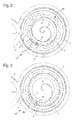
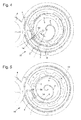
figures 2 à 6 sont des vues en plan du mode de réalisation de lafigure 1 expliquant le fonctionnement d'un système d'échappement sur deux alternances consécutives du résonateur balancier-spiral selon l'invention ; - la
figure 7 est un graphique accompagnant les explications relatives auxfigures 2 à 6 ; - la
figure 8 est un graphique comparant les couples exercés, d'une part, sur le résonateur balancier-spiral selon l'invention et, d'autre part, sur un résonateur balancier-spiral coopérant avec un système d'échappement du type à ancre suisse ; - la
figure 9 est une vue en coupe d'un système d'échappement selon lafigure 1 ; - la
figure 10 est une vue en coupe d'un système d'échappement selon un deuxième mode de réalisation ; - la
figure 11 est une vue en plan d'un système d'échappement selon un troisième mode de réalisation ; - la
figure 12 est une coupe selon XII-XII de lafigure 11 ; - la
figure 13 est une coupe selon XIII-XIII de lafigure 11 ; - la
figure 14 est une vue en plan d'un système d'échappement selon un quatrième mode de réalisation ; - la
figure 15 est une vue en plan d'un système d'échappement selon un cinquième mode de réalisation ; - la
figure 16 est une coupe selon XVI-XVI de lafigure 15 ; - la
figure 17 est une vue en perspective partielle de lafigure 15 .
- the
figure 1 is a perspective view of a first embodiment of the exhaust system according to the invention; - the
Figures 2 to 6 are plan views of the embodiment of thefigure 1 explaining the operation of an exhaust system on two consecutive alternations of the sprung-balance resonator according to the invention; - the
figure 7 is a graphic accompanying the explanations forFigures 2 to 6 ; - the
figure 8 is a graph comparing the pairs exerted, on the one hand, on the sprung-balance resonator according to the invention and, on the other hand, on a sprung-balance resonator cooperating with an escapement system of the Swiss anchor type; - the
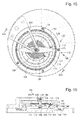
figure 9 is a sectional view of an exhaust system according to thefigure 1 ; - the
figure 10 is a sectional view of an exhaust system according to a second embodiment; - the
figure 11 is a plan view of an exhaust system according to a third embodiment; - the
figure 12 is a cup according to XII-XII of thefigure 11 ; - the
figure 13 is a section according to XIII-XIII of thefigure 11 ; - the
figure 14 is a plan view of an exhaust system according to a fourth embodiment; - the
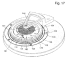
figure 15 is a plan view of an exhaust system according to a fifth embodiment; - the
figure 16 is a cup according to XVI-XVI of thefigure 15 ; - the
figure 17 is a partial perspective view of thefigure 15 .
Un premier mode de réalisation de la présente invention est illustré à la
Pour la clarté du dessin et ne pas masquer les éléments se trouvant sous lui, le spiral 2 n'est représenté que par un nombre limité de spires. Toutefois, le spiral 2 peut, bien entendu, comporter un plus grand nombre de spires sans sortir du cadre de l'invention. L'extrémité intérieure 50 du spiral 2 est fixée sur un arbre 43 comme, par exemple, au moyen d'une virole (mieux visible à la
Selon l'invention, le système d'échappement 18 comporte une roue d'échappement mobile 3 disposée coaxialement par rapport au résonateur 15. Dans l'exemple illustré à la
Le système d'échappement 18 comprend en outre une première roue fixe 5 présentant une denture extérieure 6 et une seconde roue fixe 7 présentant une denture intérieure 8. Dans l'exemple illustré à la
Avantageusement selon l'invention, la roue d'échappement mobile 3 est munie d'un dispositif 9 de fixation à l'extrémité extérieure 10 du spiral 2 pour armer ce dernier. De plus, le dispositif 9 de fixation est agencé pour assurer, selon l'état d'armage du spiral 2, un déplacement radial de l'extrémité extérieure 10, celle-ci étant amenée à coopérer alternativement avec la denture 6 de l'une puis la denture 8 de l'autre des première 5 et seconde 7 roues fixes. On comprend que ce déplacement radial permet au système d'échappement 18 d'assurer l'entretien du résonateur 15 et l'échappement de la roue de secondes 4.Advantageously according to the invention, the
Une coupe de principe exercée sur la
Comme mieux visible à la
Préférentiellement selon le premier mode de réalisation de l'invention, le dispositif 9 de fixation comporte une barrette 11 articulée pour assurer le déplacement radial de l'extrémité extérieure 10 du spiral 2. La barrette 11 est montée, d'une part, sur un piton 12 pivotant portée par la roue d'échappement mobile 3 et, d'autre part, sur l'extrémité extérieure 10 du spiral 2. Dans l'exemple illustré à la
Lors du déplacement de la cheville 14 dans le canal 56, pour faciliter son dégagement de l'une 6 puis de l'autre 8 des dents 6, 8 équipant les roues fixes 5 et 7, on peut donner à la cheville 14 la forme d'une goupille cylindrique à section circulaire ou elliptique.When moving the
On va expliquer maintenant le fonctionnement du système d'échappement 18 selon l'invention en se référant aux
- a) En
figure 2 ,le spiral 2 est en contraction maximale (point 52 sur lafigure 7 ) à partir de laquelle il entre dans une première phase d'expansion (région 53 sur lafigure 7 ) laquelle prend fin lorsqu'il atteint sa position d'équilibre,ou point mort 54, phase durant laquelle la cheville 14 est maintenue bloquée contre une dent extérieure 6 de la première roue fixe 5. - b) En
figure 3 , à partir de la position d'équilibre (point 54 sur lafigure 7 )le spiral 2 entre dans une seconde phase d'expansion (région 55 sur lafigure 7 ) au début de laquelle la cheville 14 est poussée radialement, par la déformation élastique du spiral lui-même, hors de ladent extérieure 6 de la première roue fixe 5 pour être amenée dans lecanal 56 entre deux dents intérieures 8 de la seconde roue fixe 7. On comprend donc que la cheville 14 est rendue libre par son déplacement radial par rapport auxroues - c) En
figure 4 ,la cheville 14 rendue libre et, incidemment la roue d'échappement mobile 3, sont entraînées par la roue de secondes 4 mise sous contrainte par le barillet de la pièce d'horlogerie. Par conséquent, la roue d'échappement mobile 3 se déplace d'un premier angle d'impulsion α qui amène la cheville 14, à venir buter et se bloquer contre une dent intérieure 8 de la seconde roue fixe 7. Ce déplacement conduit le spiral 2 à parcourir saseconde phase d'expansion 55 puis une première phase de contraction (région 58 sur lafigure 7 ) pendant lesquelles la cheville 14 reste bloquée contre la même dentintérieure 8. Laseconde phase d'expansion 55 et la première phase decontraction 58 définissent un premier arc supplémentaire du balancier 1. - d) En
figure 5 , la première phase decontraction 58 prend fin lorsque le spiral atteint sa position d'équilibre (point 59 sur lafigure 7 ) à partir de laquelle le spiral 2 entre dans une seconde phase de contraction (région 60 sur lafigure 7 ) au début de laquelle la cheville 14 est poussée radialement hors de ladent intérieure 8 de la seconde roue fixe 7 pour être amenée dans lecanal 56 entre deux dents extérieures 6 de la première roue fixe 5. On comprend donc que la cheville 14 est à nouveau rendue libre par son déplacement radial par rapport auxroues - e) En
figure 6 ,la cheville 14 rendue libre par son déplacement radial et, incidemment la roue d'échappement mobile 3, sont entraînées par la roue de secondes 4. Par conséquent, la roue d'échappement mobile 3 se déplaçant d'un second angle d'impulsion β qui amène la cheville 14 à venir buter et se bloquer contre une nouvelle dent extérieure 6 de la première roue fixe 5. Ce déplacement conduit le spiral 2 à parcourir sa seconde phase decontraction 60 puis une nouvelle et répétitive première phase d'expansion (région 63 sur lafigure 7 similaire à la région 53) pendant lesquelles la cheville 14 reste bloquée contre la nouvelle dentextérieure 6. La seconde phase decontraction 60 et nouvelle première phase d'expansion 63 définissent un second arc supplémentaire du balancier 1.
- a) In
figure 2 , thehairspring 2 is in maximum contraction (point 52 on thefigure 7 ) from which it enters a first phase of expansion (region 53 on thefigure 7 ) which ends when it reaches its equilibrium position, ordead point 54, phase during which thepin 14 is held locked against anouter tooth 6 of the first fixedwheel 5. - b) In
figure 3 , from the equilibrium position (point 54 on thefigure 7 spiral 2 enters a second expansion phase (region 55 on thefigure 7 ) at the beginning of which thepin 14 is pushed radially, by the elastic deformation of the spring itself, out of theouter tooth 6 of the first fixedwheel 5 to be brought into thechannel 56 between twoinner teeth 8 of the second wheel fixed 7. It is therefore understood that thepin 14 is made free by its radial displacement relative to thewheels - c) In
figure 4 , thepin 14 made free and, incidentally themovable escape wheel 3, are driven by the seconds wheel 4 put under constraint by the barrel of the timepiece. Consequently, themobile escapement wheel 3 moves at a first pulse angle α which brings thepin 14, to abut and lock against aninner tooth 8 of the second fixedwheel 7. This displacement drives thehairspring 2 to go through itssecond expansion phase 55 and then a first phase of contraction (region 58 on thefigure 7 ) during which thepin 14 remains locked against the sameinner tooth 8. Thesecond expansion phase 55 and thefirst contraction phase 58 define a first additional arc of thebalance 1. - d) In
figure 5 thefirst contraction phase 58 ends when the hairspring reaches its equilibrium position (point 59 on thefigure 7 ) from which thehairspring 2 enters a second contraction phase (region 60 on thefigure 7 ) at the beginning of which thepin 14 is pushed radially out of theinner tooth 8 of the second fixedwheel 7 to be brought into thechannel 56 between twoouter teeth 6 of the first fixedwheel 5. It is therefore understood that thepin 14 is again made free by its radial displacement relative to thewheels - e) In
figure 6 , thepin 14 made free by its radial displacement and, incidentally themovable escapement wheel 3, are driven by theseconds wheel 4. Therefore, themovable escapement wheel 3 moving from a second pulse angle β which causes thepin 14 to abut and lock against a newouter tooth 6 of the first fixedwheel 5. This movement causes thespring 2 to go through its second phase ofcontraction 60 and then a new and repetitive first phase of expansion (region 63 on thefigure 7 similar to the region 53) during which thepin 14 remains locked against the newouter tooth 6. Thesecond contraction phase 60 and newfirst expansion phase 63 define a second additional arc of thebalance 1.
Dans le premier mode de réalisation des
La
La
Par conséquent, avantageusement selon l'invention, outre l'augmentation de l'énergie mécanique Em due à l'augmentation de l'amplitude A de l'oscillation du balancier 1, le système d'échappement 18 permet de corriger les effets de gravité. On comprend également que le système d'échappement 18 offre la garantie d'auto-démarrage d'un mouvement à haute fréquence même avec une grand rigidité, l'augmentation de la stabilité et du facteur de qualité en l'absence de chocs d'entretien, l'élimination du risque de rebat et de renversement qui sont intrinsèque à l'architecture, l'amélioration du rendement des fonctions d'échappement car les pertes sont dues uniquement aux frottements dans les pivots et un mobile et la réduction du nombre de composants à huiler par la suppression de l'ancre.Therefore, advantageously according to the invention, besides the increase of the mechanical energy E m due to the increase of the amplitude A of the oscillation of the
Bien entendu, la présente invention ne se limite pas au premier mode de réalisation mais est susceptible de diverses variantes et modifications tout en conservant les effets et avantages cités ci-dessus. En particulier, un deuxième mode de réalisation de système d'échappement 21 selon l'invention est illustré à la
Un troisième mode de réalisation de système d'échappement 22 selon l'invention est illustré aux
Afin de mieux expliquer ce troisième mode de réalisation, les
Le balancier 1 est associé au spiral 24 comportant plus de spires que le spiral 2 du premier mode de réalisation et dont l'extrémité de la spire intérieure 50 est fixée à l'arbre 43 par exemple au moyen d'une virole. L'extrémité de la spire extérieure 10 est attachée à la cheville 14 fixée à l'extrémité libre 13 de la barrette 11, cette dernière étant articulée sur le piton 12 porté par la roue d'échappement mobile 3 comme pour le premier mode de réalisation. La roue d'échappement mobile 3 est munie d'une denture 73 en prise avec la roue de secondes 4 également comme pour le premier mode de réalisation et est associée à l'élément interne 40 d'un roulement à billes 41 dont l'élément externe 42 est solidaire du bloc 51 fixées à un point fixe de la pièce d'horlogerie, comme par exemple sa platine.The
Un quatrième mode de réalisation selon l'invention est illustré à la
On observe également à la
La
La seconde cheville 79 de la bascule 75 entre alors dans l'espace séparant deux secondes dents 73 ce qui libère la roue d'échappement mobile 3 qui progresse alors d'un premier angle d'impulsion par entraînement de la roue de seconde 4 jusqu'à ce que la seconde cheville 79 vienne buter contre une seconde dent 73 de la seconde roue fixe 71.The
Un second angle d'impulsion est parcouru quand, le spiral 2 passant en expansion, la seconde cheville 79 se libère de la seconde dent 73, la bascule 75 tournant alors dans le sens horaire. La première cheville 77 tombe alors dans l'espace séparant deux premières dents 72 et la roue d'échappement mobile 3 alors d'un deuxième angle d'impulsion par entraînement de la roue de seconde 4 jusqu'à ce que la première cheville 77 vienne buter contre une première dent 72 de la première roue fixe 70. On notera que dans ce quatrième mode de réalisation, les roues fixes 70 et 71 étant disposées l'une sur l'autre, la seconde cheville 79 doit présenter une longueur plus réduite par rapport à la longueur de la première cheville 77.A second pulse angle is traveled when, the
Bien entendu, la présente invention ne se limite pas à l'exemple illustré mais est susceptible de diverses variantes et modifications qui apparaîtront à l'homme de l'art. En particulier, les quatre modes de réalisation présentés ci-dessus sont susceptibles d'être combinés afin de s'adapter aux contraintes d'implantation tout en conservant les effets et avantages cités ci-dessus communs aux quatre modes de réalisation. A titre d'exemple nullement limitatif, les première 70 et seconde 71 roues fixes du quatrième mode de réalisation pourraient être faites en une seule pièce comme proposé dans le troisième mode de réalisation.Of course, the present invention is not limited to the illustrated example but is susceptible of various variations and modifications that will occur to those skilled in the art. In particular, the four embodiments presented above are capable of being combined in order to adapt to the implementation constraints while preserving the effects and advantages mentioned above common to the four embodiments. By way of non-limiting example, the first 70 and second 71 fixed wheels of the fourth embodiment could be made in one piece as proposed in the third embodiment.
Il est également possible que la pièce articulée par rapport à la roue d'échappement mobile 3, 19, 45, c'est-à-dire par la bascule 75 ou la barrette 11, soit remplacée par une pièce de forme différente telle qu'une pièce sensiblement en forme de demi-cylindre.It is also possible that the part articulated with respect to the
Dans un mode de réalisation comportant plusieurs chevilles 14, 77, 79 tel que le quatrième mode de réalisation, il peut être envisagé que les bras 76, 78 de la pièce articulée 75 par rapport à la roue d'échappement mobile 3, 19, 45 soient décalés en hauteur.In one embodiment comprising
De plus, les première et deuxième dentures 6, 8, 72, 73 doivent s'entendre comme des butées ou des surfaces de contact permettant d'arrêter et de bloquer ladite au moins une cheville 14, 77, 79. A ce titre, les première et seconde dentures 6, 8, 72, 73 peuvent être formées par des goupilles, c'est-à-dire des tiges s'étendant sensiblement parallèlement par rapport à ladite au moins une cheville 14, 77, 79 afin d'entrer en contact avec ladite au moins une cheville 14, 77, 79 selon le fonctionnement expliqué ci-dessus. On comprend donc que les première et/ou deuxième dentures 6, 8, 72, 73 peuvent en quelque sorte être squelettées, c'est-à-dire ne pas être entièrement pleines.In addition, the first and
Ainsi, un cinquième mode de réalisation de système d'échappement 122 selon l'invention est illustré aux
Afin de mieux expliquer ce cinquième mode de réalisation, les
Le balancier 101 est associé au spiral 124 comportant plus de spires que le spiral 2 du premier mode de réalisation et dont l'extrémité de la spire intérieure 150 est fixée à l'arbre 143 par exemple au moyen d'une virole. L'extrémité de la spire extérieure 110 est attachée à la cheville 114 fixée à l'extrémité libre 113 de la pièce 111 articulée.The
La pièce 111 est articulée sur le piton 112 porté par la roue d'échappement mobile 103 comme pour les autres modes de réalisation. La roue d'échappement mobile 103 est munie d'une denture 173 en prise avec la roue de secondes 4 également comme pour les autres modes de réalisation et est associée à l'élément interne 140 d'un roulement à billes 141 dont l'élément externe 142 est solidaire du bloc 151 fixées à un point fixe de la pièce d'horlogerie, comme par exemple sa platine.The
Ainsi comme mieux visible à la
On peut également voir à la
Enfin, afin d'améliorer le blocage des modes de réalisation ci-dessus, un collage magnétique entre lesdites dentures et ladite au moins une cheville peut également être prévu. Par conséquent, à titre d'exemple, ladite au moins une cheville 14, 77, 79 peut être magnétisée et les dentures 6, 8, 72, 73 ou dents 106, 108 peuvent être en matériau paramagnétique comportant une perméabilité magnétique supérieure à 1,5, ou inversement, ladite au moins une cheville 14, 77, 79 peut être magnétisée et les dentures 6, 8, 72, 73 ou dents 106, 108 peuvent être en matériau paramagnétique comportant une perméabilité magnétique supérieure à 1,5.Finally, in order to improve the locking of the above embodiments, magnetic bonding between said toothing and said at least one peg may also be provided. Therefore, by way of example, said at least one
Bien entendu, les modes de réalisation et/ou alternatives et/ou variantes cités ci-dessus sont combinables entre eux suivant les applications nécessaires.Of course, the embodiments and / or alternatives and / or variants mentioned above are combinable with each other according to the necessary applications.
Claims (21)
Priority Applications (1)
| Application Number | Priority Date | Filing Date | Title |
|---|---|---|---|
| EP14157942.5A EP2790068B1 (en) | 2013-04-12 | 2014-03-05 | Escapement system for a balance-hairspring resonator |
Applications Claiming Priority (2)
| Application Number | Priority Date | Filing Date | Title |
|---|---|---|---|
| EP13163484.2A EP2790067A1 (en) | 2013-04-12 | 2013-04-12 | Escapement system for a balance-hairspring resonator |
| EP14157942.5A EP2790068B1 (en) | 2013-04-12 | 2014-03-05 | Escapement system for a balance-hairspring resonator |
Publications (3)
| Publication Number | Publication Date |
|---|---|
| EP2790068A2 true EP2790068A2 (en) | 2014-10-15 |
| EP2790068A3 EP2790068A3 (en) | 2015-09-16 |
| EP2790068B1 EP2790068B1 (en) | 2016-11-02 |
Family
ID=48087449
Family Applications (2)
| Application Number | Title | Priority Date | Filing Date |
|---|---|---|---|
| EP13163484.2A Withdrawn EP2790067A1 (en) | 2013-04-12 | 2013-04-12 | Escapement system for a balance-hairspring resonator |
| EP14157942.5A Active EP2790068B1 (en) | 2013-04-12 | 2014-03-05 | Escapement system for a balance-hairspring resonator |
Family Applications Before (1)
| Application Number | Title | Priority Date | Filing Date |
|---|---|---|---|
| EP13163484.2A Withdrawn EP2790067A1 (en) | 2013-04-12 | 2013-04-12 | Escapement system for a balance-hairspring resonator |
Country Status (5)
| Country | Link |
|---|---|
| US (1) | US8926167B2 (en) |
| EP (2) | EP2790067A1 (en) |
| JP (1) | JP5830562B2 (en) |
| CN (1) | CN104102119B (en) |
| HK (1) | HK1203093A1 (en) |
Families Citing this family (11)
| Publication number | Priority date | Publication date | Assignee | Title |
|---|---|---|---|---|
| RU2606342C2 (en) * | 2012-03-29 | 2017-01-10 | Ниварокс-Фар С.А. | Flexible anchor mechanism with balance without roller |
| EP3032351A1 (en) * | 2014-12-09 | 2016-06-15 | LVMH Swiss Manufactures SA | Timepiece mechanism, timepiece movement and timepiece having such a mechanism |
| EP3128379B1 (en) * | 2015-08-04 | 2019-10-02 | The Swatch Group Research and Development Ltd. | Escapement with escape wheel with field rramps and a non-return device |
| CH711402A2 (en) * | 2015-08-04 | 2017-02-15 | Eta Sa Mft Horlogere Suisse | Magnetically synchronized rotary arm clock regulator mechanism. |
| EP3147725B1 (en) * | 2015-09-28 | 2018-04-04 | Nivarox-FAR S.A. | Oscillator with rotary detent |
| EP3182213B2 (en) * | 2015-12-16 | 2020-10-21 | Société anonyme de la Manufacture d'Horlogerie Audemars Piguet & Cie | Mechanism for adjusting an average speed in a clock movement and clock movement |
| ITUA20162454A1 (en) * | 2016-03-22 | 2017-09-22 | Giovanni Domenico Maria Cefis | ESCAPEMENT FOR CLOCKS MECHANISMS |
| CH712726A2 (en) * | 2016-07-21 | 2018-01-31 | Montres Breguet Sa | Pendulum oscillator-spiral clock with magnetic pivot. |
| WO2019106448A1 (en) * | 2017-10-02 | 2019-06-06 | Société Anonyme De La Manufacture D’Horlogerie Audemars Piguet & Cie | Timepiece setting device with harmonic oscillator having rotating weights and a common recoil strength |
| JP1624216S (en) * | 2017-12-21 | 2019-02-12 | ||
| EP3579058B1 (en) * | 2018-06-07 | 2021-09-15 | Montres Breguet S.A. | Timepiece comprising a tourbillon |
Family Cites Families (10)
| Publication number | Priority date | Publication date | Assignee | Title |
|---|---|---|---|---|
| US1232285A (en) * | 1916-10-19 | 1917-07-03 | John H Greeley | Escapement for clocks and watches. |
| FR690365A (en) * | 1930-02-21 | 1930-09-19 | Escapement of clocks and watches | |
| CH148185A (en) * | 1930-02-28 | 1931-07-15 | L Braunschweig Fabrique Electi | Device for regulating the control of a rotary member driven in clockwork movements, counters, etc. |
| US1895666A (en) * | 1931-05-22 | 1933-01-31 | Junghans Helmut | Anchor escapement for clocks and the like |
| DE547261C (en) * | 1931-05-23 | 1932-03-29 | Helmut Junghans | Lever escapement for watches |
| EP2141555B1 (en) * | 2008-07-04 | 2011-04-06 | The Swatch Group Research and Development Ltd. | Coupled resonators for timepiece |
| CH702156B1 (en) * | 2009-11-13 | 2017-08-31 | Nivarox Far Sa | Spiral balance resonator for a timepiece. |
| EP2466397B1 (en) * | 2010-12-20 | 2013-08-21 | Blancpain S.A. | Rotating clock component with peripheral guide |
| CH704611B1 (en) * | 2011-03-07 | 2020-02-28 | Montres Breguet Sa | Escapement and oscillator device for a mechanical watch. |
| EP2570871B1 (en) * | 2011-09-14 | 2014-03-19 | Montres Breguet SA | Hairspring with two spiral springs |
-
2013
- 2013-04-12 EP EP13163484.2A patent/EP2790067A1/en not_active Withdrawn
-
2014
- 2014-03-05 EP EP14157942.5A patent/EP2790068B1/en active Active
- 2014-03-20 US US14/220,223 patent/US8926167B2/en active Active
- 2014-04-04 JP JP2014077514A patent/JP5830562B2/en active Active
- 2014-04-11 CN CN201410145416.2A patent/CN104102119B/en active Active
-
2015
- 2015-04-13 HK HK15103585.8A patent/HK1203093A1/en unknown
Non-Patent Citations (1)
| Title |
|---|
| None |
Also Published As
| Publication number | Publication date |
|---|---|
| EP2790068B1 (en) | 2016-11-02 |
| CN104102119B (en) | 2017-04-12 |
| US20140307530A1 (en) | 2014-10-16 |
| JP2014206534A (en) | 2014-10-30 |
| JP5830562B2 (en) | 2015-12-09 |
| EP2790068A3 (en) | 2015-09-16 |
| HK1203093A1 (en) | 2015-10-16 |
| US8926167B2 (en) | 2015-01-06 |
| EP2790067A1 (en) | 2014-10-15 |
| CN104102119A (en) | 2014-10-15 |
Similar Documents
| Publication | Publication Date | Title |
|---|---|---|
| EP2790068B1 (en) | Escapement system for a balance-hairspring resonator | |
| EP3548973B1 (en) | Device for timepiece, clockwork mechanism and timepiece comprising such a device. | |
| WO2018095594A1 (en) | Rotary resonator with a flexible guide system based on a detached lever escapement | |
| EP2397921B1 (en) | Mechanism for a jumping tourbillon cage | |
| EP2706416A1 (en) | Constant force flexible anchor | |
| EP2613206A1 (en) | Hairspring with two spiral springs with improved isochronism | |
| EP3579058B1 (en) | Timepiece comprising a tourbillon | |
| CH715049B1 (en) | Timepiece comprising a tourbillon. | |
| EP3430479B1 (en) | Device for a timepiece, timepiece movement and timepiece comprising a device of said type | |
| EP2466397B1 (en) | Rotating clock component with peripheral guide | |
| EP3021173B1 (en) | Annular oscillating mass and timepiece comprising such an oscillating mass | |
| FR2928015A1 (en) | Tangential impulse pallet escapement device for mechanical watch, has escape wheel with teeth, pallet and two spiral-timed balance motors, and forks using driven force on ellipses of large plates in corresponding motors | |
| CH707881A2 (en) | Exhaust system for a sprung balance resonator. | |
| WO2019201976A1 (en) | Escapement mechanism with a rest lever and timepiece provided with such an escapement mechanism | |
| EP3663868B1 (en) | Clock movement including a tourbillon with a fixed magnetic wheel | |
| EP2515185B1 (en) | Engine with constant torque | |
| EP3206088A1 (en) | Escapement mechanism | |
| CH709811B1 (en) | Oscillating system for watch movement with anchor escapement. | |
| CH715531A2 (en) | Regulating organ for watch. | |
| EP3019916A2 (en) | Escapement for a timepiece with a tourbillon without a cage | |
| CH715618A2 (en) | Clock movement comprising a tourbillon with a fixed magnetic wheel. | |
| CH710487B1 (en) | Tourbillon mechanism for watch movement. | |
| CH703330B1 (en) | advance mechanism by periodically skipping a carousel cage. | |
| CH706756B1 (en) | Exhaust anchor timepiece. | |
| CH704239A2 (en) | Single block watch making mobile e.g. escape mechanism, for use during movement of mechanical watch, has guide surface located close to plane so as to maintain mobile in recessed or overhang manner, where mobile does not have guide shaft |
Legal Events
| Date | Code | Title | Description |
|---|---|---|---|
| PUAI | Public reference made under article 153(3) epc to a published international application that has entered the european phase |
Free format text: ORIGINAL CODE: 0009012 |
|
| 17P | Request for examination filed |
Effective date: 20140305 |
|
| AK | Designated contracting states |
Kind code of ref document: A2 Designated state(s): AL AT BE BG CH CY CZ DE DK EE ES FI FR GB GR HR HU IE IS IT LI LT LU LV MC MK MT NL NO PL PT RO RS SE SI SK SM TR |
|
| AX | Request for extension of the european patent |
Extension state: BA ME |
|
| PUAL | Search report despatched |
Free format text: ORIGINAL CODE: 0009013 |
|
| AK | Designated contracting states |
Kind code of ref document: A3 Designated state(s): AL AT BE BG CH CY CZ DE DK EE ES FI FR GB GR HR HU IE IS IT LI LT LU LV MC MK MT NL NO PL PT RO RS SE SI SK SM TR |
|
| AX | Request for extension of the european patent |
Extension state: BA ME |
|
| RIC1 | Information provided on ipc code assigned before grant |
Ipc: G04B 15/08 20060101AFI20150810BHEP Ipc: G04B 15/14 20060101ALI20150810BHEP |
|
| R17P | Request for examination filed (corrected) |
Effective date: 20160316 |
|
| RBV | Designated contracting states (corrected) |
Designated state(s): AL AT BE BG CH CY CZ DE DK EE ES FI FR GB GR HR HU IE IS IT LI LT LU LV MC MK MT NL NO PL PT RO RS SE SI SK SM TR |
|
| GRAP | Despatch of communication of intention to grant a patent |
Free format text: ORIGINAL CODE: EPIDOSNIGR1 |
|
| RIC1 | Information provided on ipc code assigned before grant |
Ipc: G04B 15/14 20060101ALI20160606BHEP Ipc: G04B 15/08 20060101AFI20160606BHEP |
|
| INTG | Intention to grant announced |
Effective date: 20160620 |
|
| GRAS | Grant fee paid |
Free format text: ORIGINAL CODE: EPIDOSNIGR3 |
|
| GRAA | (expected) grant |
Free format text: ORIGINAL CODE: 0009210 |
|
| AK | Designated contracting states |
Kind code of ref document: B1 Designated state(s): AL AT BE BG CH CY CZ DE DK EE ES FI FR GB GR HR HU IE IS IT LI LT LU LV MC MK MT NL NO PL PT RO RS SE SI SK SM TR |
|
| REG | Reference to a national code |
Ref country code: GB Ref legal event code: FG4D Free format text: NOT ENGLISH |
|
| REG | Reference to a national code |
Ref country code: AT Ref legal event code: REF Ref document number: 842432 Country of ref document: AT Kind code of ref document: T Effective date: 20161115 Ref country code: CH Ref legal event code: NV Representative=s name: ICB INGENIEURS CONSEILS EN BREVETS SA, CH Ref country code: CH Ref legal event code: EP |
|
| REG | Reference to a national code |
Ref country code: IE Ref legal event code: FG4D Free format text: LANGUAGE OF EP DOCUMENT: FRENCH |
|
| REG | Reference to a national code |
Ref country code: DE Ref legal event code: R096 Ref document number: 602014004534 Country of ref document: DE |
|
| REG | Reference to a national code |
Ref country code: FR Ref legal event code: PLFP Year of fee payment: 4 |
|
| PG25 | Lapsed in a contracting state [announced via postgrant information from national office to epo] |
Ref country code: LV Free format text: LAPSE BECAUSE OF FAILURE TO SUBMIT A TRANSLATION OF THE DESCRIPTION OR TO PAY THE FEE WITHIN THE PRESCRIBED TIME-LIMIT Effective date: 20161102 |
|
| REG | Reference to a national code |
Ref country code: NL Ref legal event code: MP Effective date: 20161102 |
|
| REG | Reference to a national code |
Ref country code: LT Ref legal event code: MG4D |
|
| REG | Reference to a national code |
Ref country code: AT Ref legal event code: MK05 Ref document number: 842432 Country of ref document: AT Kind code of ref document: T Effective date: 20161102 |
|
| PG25 | Lapsed in a contracting state [announced via postgrant information from national office to epo] |
Ref country code: LT Free format text: LAPSE BECAUSE OF FAILURE TO SUBMIT A TRANSLATION OF THE DESCRIPTION OR TO PAY THE FEE WITHIN THE PRESCRIBED TIME-LIMIT Effective date: 20161102 Ref country code: NL Free format text: LAPSE BECAUSE OF FAILURE TO SUBMIT A TRANSLATION OF THE DESCRIPTION OR TO PAY THE FEE WITHIN THE PRESCRIBED TIME-LIMIT Effective date: 20161102 Ref country code: GR Free format text: LAPSE BECAUSE OF FAILURE TO SUBMIT A TRANSLATION OF THE DESCRIPTION OR TO PAY THE FEE WITHIN THE PRESCRIBED TIME-LIMIT Effective date: 20170203 Ref country code: SE Free format text: LAPSE BECAUSE OF FAILURE TO SUBMIT A TRANSLATION OF THE DESCRIPTION OR TO PAY THE FEE WITHIN THE PRESCRIBED TIME-LIMIT Effective date: 20161102 Ref country code: NO Free format text: LAPSE BECAUSE OF FAILURE TO SUBMIT A TRANSLATION OF THE DESCRIPTION OR TO PAY THE FEE WITHIN THE PRESCRIBED TIME-LIMIT Effective date: 20170202 |
|
| PG25 | Lapsed in a contracting state [announced via postgrant information from national office to epo] |
Ref country code: PT Free format text: LAPSE BECAUSE OF FAILURE TO SUBMIT A TRANSLATION OF THE DESCRIPTION OR TO PAY THE FEE WITHIN THE PRESCRIBED TIME-LIMIT Effective date: 20170302 Ref country code: HR Free format text: LAPSE BECAUSE OF FAILURE TO SUBMIT A TRANSLATION OF THE DESCRIPTION OR TO PAY THE FEE WITHIN THE PRESCRIBED TIME-LIMIT Effective date: 20161102 Ref country code: IS Free format text: LAPSE BECAUSE OF FAILURE TO SUBMIT A TRANSLATION OF THE DESCRIPTION OR TO PAY THE FEE WITHIN THE PRESCRIBED TIME-LIMIT Effective date: 20170302 Ref country code: PL Free format text: LAPSE BECAUSE OF FAILURE TO SUBMIT A TRANSLATION OF THE DESCRIPTION OR TO PAY THE FEE WITHIN THE PRESCRIBED TIME-LIMIT Effective date: 20161102 Ref country code: AT Free format text: LAPSE BECAUSE OF FAILURE TO SUBMIT A TRANSLATION OF THE DESCRIPTION OR TO PAY THE FEE WITHIN THE PRESCRIBED TIME-LIMIT Effective date: 20161102 Ref country code: FI Free format text: LAPSE BECAUSE OF FAILURE TO SUBMIT A TRANSLATION OF THE DESCRIPTION OR TO PAY THE FEE WITHIN THE PRESCRIBED TIME-LIMIT Effective date: 20161102 Ref country code: ES Free format text: LAPSE BECAUSE OF FAILURE TO SUBMIT A TRANSLATION OF THE DESCRIPTION OR TO PAY THE FEE WITHIN THE PRESCRIBED TIME-LIMIT Effective date: 20161102 Ref country code: RS Free format text: LAPSE BECAUSE OF FAILURE TO SUBMIT A TRANSLATION OF THE DESCRIPTION OR TO PAY THE FEE WITHIN THE PRESCRIBED TIME-LIMIT Effective date: 20161102 |
|
| PG25 | Lapsed in a contracting state [announced via postgrant information from national office to epo] |
Ref country code: SK Free format text: LAPSE BECAUSE OF FAILURE TO SUBMIT A TRANSLATION OF THE DESCRIPTION OR TO PAY THE FEE WITHIN THE PRESCRIBED TIME-LIMIT Effective date: 20161102 Ref country code: RO Free format text: LAPSE BECAUSE OF FAILURE TO SUBMIT A TRANSLATION OF THE DESCRIPTION OR TO PAY THE FEE WITHIN THE PRESCRIBED TIME-LIMIT Effective date: 20161102 Ref country code: CZ Free format text: LAPSE BECAUSE OF FAILURE TO SUBMIT A TRANSLATION OF THE DESCRIPTION OR TO PAY THE FEE WITHIN THE PRESCRIBED TIME-LIMIT Effective date: 20161102 Ref country code: EE Free format text: LAPSE BECAUSE OF FAILURE TO SUBMIT A TRANSLATION OF THE DESCRIPTION OR TO PAY THE FEE WITHIN THE PRESCRIBED TIME-LIMIT Effective date: 20161102 Ref country code: DK Free format text: LAPSE BECAUSE OF FAILURE TO SUBMIT A TRANSLATION OF THE DESCRIPTION OR TO PAY THE FEE WITHIN THE PRESCRIBED TIME-LIMIT Effective date: 20161102 |
|
| REG | Reference to a national code |
Ref country code: DE Ref legal event code: R097 Ref document number: 602014004534 Country of ref document: DE |
|
| PG25 | Lapsed in a contracting state [announced via postgrant information from national office to epo] |
Ref country code: BG Free format text: LAPSE BECAUSE OF FAILURE TO SUBMIT A TRANSLATION OF THE DESCRIPTION OR TO PAY THE FEE WITHIN THE PRESCRIBED TIME-LIMIT Effective date: 20170202 Ref country code: IT Free format text: LAPSE BECAUSE OF FAILURE TO SUBMIT A TRANSLATION OF THE DESCRIPTION OR TO PAY THE FEE WITHIN THE PRESCRIBED TIME-LIMIT Effective date: 20161102 Ref country code: SM Free format text: LAPSE BECAUSE OF FAILURE TO SUBMIT A TRANSLATION OF THE DESCRIPTION OR TO PAY THE FEE WITHIN THE PRESCRIBED TIME-LIMIT Effective date: 20161102 |
|
| PLBE | No opposition filed within time limit |
Free format text: ORIGINAL CODE: 0009261 |
|
| STAA | Information on the status of an ep patent application or granted ep patent |
Free format text: STATUS: NO OPPOSITION FILED WITHIN TIME LIMIT |
|
| 26N | No opposition filed |
Effective date: 20170803 |
|
| PG25 | Lapsed in a contracting state [announced via postgrant information from national office to epo] |
Ref country code: MC Free format text: LAPSE BECAUSE OF FAILURE TO SUBMIT A TRANSLATION OF THE DESCRIPTION OR TO PAY THE FEE WITHIN THE PRESCRIBED TIME-LIMIT Effective date: 20161102 Ref country code: SI Free format text: LAPSE BECAUSE OF FAILURE TO SUBMIT A TRANSLATION OF THE DESCRIPTION OR TO PAY THE FEE WITHIN THE PRESCRIBED TIME-LIMIT Effective date: 20161102 |
|
| REG | Reference to a national code |
Ref country code: IE Ref legal event code: MM4A |
|
| PG25 | Lapsed in a contracting state [announced via postgrant information from national office to epo] |
Ref country code: LU Free format text: LAPSE BECAUSE OF NON-PAYMENT OF DUE FEES Effective date: 20170305 |
|
| REG | Reference to a national code |
Ref country code: FR Ref legal event code: PLFP Year of fee payment: 5 |
|
| PG25 | Lapsed in a contracting state [announced via postgrant information from national office to epo] |
Ref country code: IE Free format text: LAPSE BECAUSE OF NON-PAYMENT OF DUE FEES Effective date: 20170305 |
|
| REG | Reference to a national code |
Ref country code: BE Ref legal event code: MM Effective date: 20170331 |
|
| PG25 | Lapsed in a contracting state [announced via postgrant information from national office to epo] |
Ref country code: BE Free format text: LAPSE BECAUSE OF NON-PAYMENT OF DUE FEES Effective date: 20170331 |
|
| PG25 | Lapsed in a contracting state [announced via postgrant information from national office to epo] |
Ref country code: MT Free format text: LAPSE BECAUSE OF FAILURE TO SUBMIT A TRANSLATION OF THE DESCRIPTION OR TO PAY THE FEE WITHIN THE PRESCRIBED TIME-LIMIT Effective date: 20161102 |
|
| PG25 | Lapsed in a contracting state [announced via postgrant information from national office to epo] |
Ref country code: HU Free format text: LAPSE BECAUSE OF FAILURE TO SUBMIT A TRANSLATION OF THE DESCRIPTION OR TO PAY THE FEE WITHIN THE PRESCRIBED TIME-LIMIT; INVALID AB INITIO Effective date: 20140305 |
|
| PG25 | Lapsed in a contracting state [announced via postgrant information from national office to epo] |
Ref country code: CY Free format text: LAPSE BECAUSE OF FAILURE TO SUBMIT A TRANSLATION OF THE DESCRIPTION OR TO PAY THE FEE WITHIN THE PRESCRIBED TIME-LIMIT Effective date: 20161102 |
|
| PG25 | Lapsed in a contracting state [announced via postgrant information from national office to epo] |
Ref country code: MK Free format text: LAPSE BECAUSE OF FAILURE TO SUBMIT A TRANSLATION OF THE DESCRIPTION OR TO PAY THE FEE WITHIN THE PRESCRIBED TIME-LIMIT Effective date: 20161102 |
|
| PG25 | Lapsed in a contracting state [announced via postgrant information from national office to epo] |
Ref country code: TR Free format text: LAPSE BECAUSE OF FAILURE TO SUBMIT A TRANSLATION OF THE DESCRIPTION OR TO PAY THE FEE WITHIN THE PRESCRIBED TIME-LIMIT Effective date: 20161102 |
|
| PG25 | Lapsed in a contracting state [announced via postgrant information from national office to epo] |
Ref country code: AL Free format text: LAPSE BECAUSE OF FAILURE TO SUBMIT A TRANSLATION OF THE DESCRIPTION OR TO PAY THE FEE WITHIN THE PRESCRIBED TIME-LIMIT Effective date: 20161102 |
|
| PGFP | Annual fee paid to national office [announced via postgrant information from national office to epo] |
Ref country code: FR Payment date: 20230222 Year of fee payment: 10 |
|
| PGFP | Annual fee paid to national office [announced via postgrant information from national office to epo] |
Ref country code: GB Payment date: 20230222 Year of fee payment: 10 Ref country code: DE Payment date: 20230221 Year of fee payment: 10 |
|
| P01 | Opt-out of the competence of the unified patent court (upc) registered |
Effective date: 20230611 |
|
| PGFP | Annual fee paid to national office [announced via postgrant information from national office to epo] |
Ref country code: CH Payment date: 20230402 Year of fee payment: 10 |